

Page 1

'
,*,
,
167$//$7,21
'
0
(6.723
$18$/
6(5·6
8
*
8,'(
)HEUXDU\
023')
Page 2

Matrox®, DigiSuite®, and Movie-2® are registered trademarks of Matrox Electronic Systems Ltd.
DigiDesktop™, DigiMix™, DigiMotion™, DigiSDK™, DigiTools™, DigiUtils™, DigiVid™, and Marvel
Millennium™ are trademarks of Matrox Electronic Systems Ltd.
MGA™ and MGA Millennium™ are trademarks of Matrox Graphics Inc.
DigiLinx™ is a trademark of Miranda Technologies Inc.
Genie™ is a trademark of Pinnacle Systems Inc.
®
Intel
and Pentium® are registered trademarks of Intel Corporation.
®
Microsoft
and Windows NT® are registered trademarks of Microsoft Corporation.
ActiveMovie™ and Video for Windows™ are trademarks of Microsoft Corporation.
All other nationally and internationally recognized trademarks and tradenames are hereby
acknowledged.
© Copyright Matrox Electronic Systems Ltd., 1998. All rights reserved.
Disclaimer: Matrox Electronic Systems Ltd. reserves the right to make changes in specifications at any
time and without notice. The information provided by this document is believed to be accurate and
reliable. However, no responsibility is assumed by Matrox Electronic Systems Ltd. for its use; nor for
any infringement s of patents or other rights of third part ies res ul t in g fro m its us e. No license is grante d
under any patents or patent rights of Matrox Electronic Systems Ltd.
Matrox Electronic Systems Ltd.
Video Products Group
1055 St. Regis Blvd., Dorval, Quebec, Canada H9P 2T4
Tel: (514) 685-2630 Fax: (514) 685-2853 World Wide Web:
www.matrox.com/video
Page 3

Table of Contents
Chapter 1
Welc ome t o DigiDesktop ............. .. .............. .. ............. .. .. .............. .. .. ....... 1
DigiD e s k t o p — st a t e of th e a rt .......... .... ..... .. .... ..... .... .. ..... .... .. ..... .... ..... 2
Feat ur e s............ ..... .... .. ..... .... ... .... .... ..... .. .... ..... .... .. ..... .... .. ..... .... ..... 2
System requirements ..................................................................2
DigiD e s k t o p d oc u m e n t a ti o n ............... ..... .... .. ..... .... .. ..... .... ..... .. .... ..... 3
About this manual.................................................................................4
Style con v enti o ns ............................ ... .......................... .. ................ 4
DigiD e s k t o p a cc e s s o ries ........... ... .... .... ..... .. .... ..... .... .. ..... .... .. ..... .... ..... 5
Chapter 2
Hard ware I nsta l lation .............. .. ........................... .. .......................... ... .. 7
Before you begin .................................................................................. 8
Antis t a tic and sa f e t y p r e ca u t i o ns ...... .... .. ..... .... .... ... .... .... ..... .. ..... .. 8
Make s u r e y o u r co m pu t e r is co m p a t ib le............... ..... .... .. ..... .... ... .. 9
DigiD e s k t o p i n st a l la t i o n ov e rv i e w .. .... .. ..... .... ..... .. .... ..... .. .... ..... .... .. ..... 9
Choose th e bes t inst allat ion position ..................... .. ......................... 10
Identify your expansion slots ...........................................................11
Use t he PC I reta i ner brack ets......... ............. .. .. .............. .. .. ............. ... 12
Install n o n-Di giSui te ca r ds fi r st! . .............. .. .. ............. .. ... ............. .. .. ... 12
Dete rm i n e yo u r D i g i Su i t e ca r d s e t or d e r........ ..... .... .... ... .... .... ... .... ..... 13
1. Di g iDes ktop by it s elf ......... .. .. .............. .. .. ............. .. ... ......... 1 3
2. Di g iMix , Dig i Motion, a n d DigiDesktop .............................. .. ..... 13
3. DigiLinx, D ig iMix, DigiMotion , DigiDesktop, a nd ................... .....
Genie .................................................................................................. 14
Installin g DigiDes ktop by it self ...... .. .. ............. .. ... ............. .. ................ 14
Take care of your Movie- 2 bus —Imp o rtan t ! ............. .. .............. .. .. ..... 16
Insta l l i ng D i g iD e sk top w it h ot h e r Di g iS u i t e ca r d s.............. .... ..... .... ... 17
Configuring your system BIOS settings ............................................20
BIOS s e t t in g s fo r D ig i D e s kt o p P C I sl o t............... ..... .... .... ... .... ..... 20
i
Table of Contents
Page 4

ii
Chapter 3
Chapter 4
Chapter 5
Software Inst a llation a n d Monitor Setup .... .. .. ............. .. .................... 2 1
Disp lay d r i ver i nstallati on ..................... ... .. ............. .. .. .............. .. .. .. 22
Moni to r S e tu p .... .... .. ..... .... .. ..... .... ..... .. .... ..... .... .. ..... .... .. ..... .... .... ... .... .. 23
To ch eck y o ur mo nitor set t ings .......... .............. .. .. ............. .. ... ...... 2 3
Disp la y se t u p ................ .. .... ..... .... .. ..... .... .. ..... .... ..... .. .... ..... .... .. ..... .... .. 23
Insta l l i ng D i g iU t i l s ................ .... ..... .. .... ..... .... .. ..... .... .. ..... .... .... ... .... .. 24
Conf i guri ng DigiDesktop....... .............. .. .. ............. .. ........................... .. .. 25
Starting t he co nfigurat i on program .... .. .. ............. ... .. ............. .. .. ......... 26
Conf ig u r in g t h e v i de o i n pu t s ig n als ...... ..... .... .. ..... .... .... ... .... .... ..... .. .. 26
Conf ig u r in g t h e v i de o w i n do w s . .... ..... .... .. ..... .... .. ..... .... ..... .. .... ..... .... .. 28
Disp la y i ng D i g iD e s k to p i n fo r m a t io n ....... ..... .... .... ... .... .... ..... .. .... ..... .. .. 29
Troubleshooting .................................................................................... 31
Problems and possible solutions....................................................... 32
Insta l l a t io n p ro b l e ms .................. .... .. ..... .... ..... .. .... ..... .. .... ..... .... .. 32
General operating problems......................................................... 32
If no thing works! ................. .. ... ............. .. ............. ... .. ............. .. .. ......... 33
Appendix A
DigiDesktop Specifications ..................................................................35
Electrical specifications ..................................................................... 36
Mechanical specifications ................................................................. 36
Envi r onme n tal s pecifications ............ .. .. ............. ... .......................... .. 36
DigiDesktop block diagram .............. .. ........................... .. ............... 37
Conne c t o r c a b le o v e rv i e w......... .... ... .... .... ... .... .... ..... .. .... ..... .... .. ..... .... 38
Table of Contents
Operating voltages and currents.................................................. 36
Phys i cal d i mens ions... .. .............. .. .. ............. .. ... ............. .. .. ........... 36
Conne c t o r t y p es ..... .... .... ... .... ..... .... .. ..... .... .... ... .... .... ... .... .... ..... .. .. 36
Bracket connector (on card) ......................................................39
Page 5

VGA m onit or cable o utput ...... .. ............. .. ... ............. .. .. .............. 40
Y/C ( S-Vi d eo) cable inpu t ............... ... .. ............. .. .............. 40
Appendix B
DigiSuite Hardware Glossary................................................................ 41
Appendix C
Technical Support ................................................................................45
DigiDesktop technical support ...........................................................46
Cont a ct i n g us b y vo i c e , f a x , o r Em a i ll.. .... ..... .... .. ..... .... .. ..... .... ..... 46
Worl d Wide Web .............. .. .. .............. .. .. ............. .. ....................... 46
Driver updates by FTP or BBS ..................................................46
Index .................................................................................................................47
iii
Table of Contents
Page 6

iv
Table of Contents
Page 7

Chapter
Welcome to DigiDesktop
This chapter outlines some of the powerful fea tur es of
your DigiDesktop, lists its computer system
requirements, and briefly describes this manual’s
contents.
1
Page 8

2
DigiDesktop — state of the art
Features
q
Two graphic display co ntrolle rs w ith ind epen dent no n-in terlac ed
output.
q
Dual-screen Windows NT desktop.
q
Ultra-high resolution up to 1600 × 1200 × 24- bit color.
q
Accelerated 3D modeling.
q
Up to four simultane ous video wi ndows.
q
Four Composite or four Y/C video inputs.
q
Two independent YUV 4:2:2 video de coders.
q
Multiple YUV 4:2:2 video input sources over the Movie -2 bus.
q
PCI mezzanine connector that supports daughte r-board
expandability.
System requirements
DigiDesktop requires the following minimum system configuration:
q
A Pentium microprocessor, 166 megahertz (MHz) or higher.
q
32 megabytes (MB) of RAM.
q
One empty 32-bit PCI ca rd sl ot.
q
Windows NT operating system version 4.0 (Service Pack 3
recommended).
Chapter 1: Welcome to DigiDesktop
Page 9

DigiDesktop documentation
Most of the information you’ll require to install and work with
DigiDesktop is included in this manual. However, you may need to
consult the following d ocume ntatio n for additiona l infor mat ion:
The DigiSuite Installation Manual provides additional information for
installing the individual components to assemble a state-of-the-art audio/
video system tailored to your sp ecific nee ds.
Any important information that wasn't available for inclusion in the
manual at print time is provided to you in one or more of the following
ways:
q
The readme.1st file in the DigiUtils/Docs directory on the DigiSuite
CD-ROM.
q
Other essential information provided in a readme file installed with
the software in the Matrox DigiSuite Utilities folder.
q
Printed Release Notes packaged with the manuals (if required).
3
DigiDesktop documentation
Page 10

4
About this ma nu al
This manual contain s the follow ing info rm ation:
Chapter 1, “Welcome to DigiDesktop,” contains information about
DigiDesktop features, system requirements, and the available
documentation.
Chapter 2, “Hardware Installation,” guides you through the pr ocess of
installing the DigiDesktop card in your system.
Chapter 3, “Software Installation and Monitor Setup, ” has step-by-step
instructions on installing the drivers and utility software for DigiDesktop
as well as on setting up y our m onitor.
Chapter 4, “Configuring DigiDesktop,” explains how to change various
settings and defaults on your D igiDe sktop c ard.
Chapter 5, “Troubleshooting,” suggests solutions to various installation
and configuration prob lems.
Appendix A, “DigiDesktop Specifications,” contains DigiDesktop
technical information.
Appendix B, “DigiSuite Hardware Glossary,” serves a s a reference for the
terminology used in the various DigiSuite manuals.
Appendix C, “Technical Support,” lets you know how to contac t us for
technical support.
Style conventions
The following style conventions are use d in this manual:
q
The names of files, directory path s, and manua ls appear in italics.
For example:
– The data is stored in the sample.wav file.
– The file is located in your C:\Windows\System directory.
– Please refer to your DigiSuite Installation Manual.
q
Menus and command s that you ne ed to ch oose are disp laye d in the
Menu | Command. For example, File | Save means click File
form
in the menu bar, then click
q
The names of keys a re displa yed in sm all capital bold letters, suc h
CTRL key.
as the
Chapter 1: Welcome to DigiDesktop
Save in the menu that appears.
Page 11

DigiDesktop accessories
q
Tw o cables (DTOP/IO/CBL), each of which provides the following
connectors:
– Two Y/C (S-Video) inputs
– One VGA output
q
Four Y/C-to-composit e adaptors (ILMPRO-BNC-ADP) so th at each
cable supports two composite inputs.
5
DigiDesktop accessories
Page 12

6
Chapter 1: Welcome to DigiDesktop
Page 13

Chapter
Hardware Installation
This chapter describes how to install the DigiDesktop
card in your computer system.
2
Page 14

8
Before you begin
Antistatic and safety precautions
Read the following information carefully before installing DigiDesktop
in your computer system.
CAUTION
STATIC DISCHARGE
Static electricity from your bo dy can damage your DigiSuite cards, Movie-2
bus, or your computer. Although you may not notice it, static electricity is
generated every time yo u move. It’s often too small to cause a spark, but
it can still cause damage to sensitive electronic components or at least
reduce their lifespan.
To avoid damage, please observe the following precautions:
q
Do not remove DigiSuite cards from their antistatic bags until you are
ready to install them. Before removing the cards, place the packages
within easy reach of the area where you intend to perform the
installation.
q
Try to work in an area where the relative humidity is at least 50%.
q
Do not wear wool or sy nthe tic clothin g. Th ese fabric s tend to
generate more static electricity than cotton, which is best for this
kind of work.
q
Turn off the power switches on your c omputer and its c onnec ted
components.
q
Once you’ve opened your computer, drain static electricity from your
body by touching a bare metal surf ace on y our comp ute r cha ssis
before you install or remove any parts of your system. If you have a
grounding wrist strap, use it while handling and installing any
components in your comp uter.
Chapter 2: Hardware Installation
Page 15

Make sure your computer is compatible
T o make sure that yo ur computer is compatibl e with the DigiSuite card s
you’ll be installing, refer to the Matrox DigiSuite Compatibility List.
To obtain this list, visit our Web site at:
http://www.matrox.com/video.
You c an a lso call M atrox Video Products Group Sales at:
800-361-4093 ..............................................................U.S. and Canada
(514) 685-2630 ext. 26 36... .... ... ... ... ... ... ... ... ... ....... ... ... ... ... ... .. Worldwide
DigiDesktop installation overview
Warning Failure to read the detailed instructions may result in broken
parts and/or system malfunctions.
The following steps summarize the DigiDesktop installation procedure.
Each step is explained in detail in the following sections. This list is
simply to give you an ov er view. Do not attempt to insta ll Di giDesk top
without reading the detailed instructions that follow.
„ The following steps summarize the installation process:
1. Prepare your com puter an d DigiD esktop fo r in stallation.
2. Open your computer and identify the expansion slot in which you’ll
install DigiDesktop.
3. Insert the card.
4. Close y our c ompute r's c over.
5. Configur e your system BIOS.
6. Conne ct your exte rnal d evi ces.
7. Install your software as outlined in Chapter 3, “Software Installation
and Monitor Setup,” on page 21.
9
DigiDesktop installation overview
Page 16
10
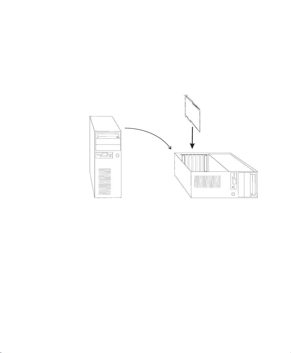
Choose the best installation position
It’s easiest to install DigiDesktop from above. For typical desktop
systems, this is easy because access to the expansion slots in such systems
is from the top. If, how eve r, you have a to wer-type system a nd want to
insert the DigiDesktop f rom a bov e, p lac e the c om puter on its side, as
illustrated in the following diagram:
1
Place tower on
its side
2
Install components
vertically
Chapter 2: Hardware Installation
Page 17

Identify your expansion slots
DigiDesktop is installed in one of your computer’s expansion slots. Most
PCI-bus computers currently manuf actured have a combination of PCI
and ISA slots. Usua lly, the PCI slots ar e made with a pl asti c of a
contrasting color (generally white) and are shorter than the ISA slots in
your system.
While some comp ut er mot h er board s h ave n umb er ed slo ts , the se do not
follow any standar d industr y con ve ntion. For exa mp le, one c omputer
may have three PCI slots and four ISA, whereas another may have four
PCI slots and three ISA slots, and so on .
To avoid confusion, use the following numbering scheme to identify each
slot position. Since all PCI-based systems have two types of slots, there
is always one PCI slot bordering the other type (usu ally ISA). Start
counting outwards from this “border” in each direction for each type. In
the following di agram, there are thre e PCI slot s referre d to as P1, P 2,
and P3. Ther e are a lso four I SA s lots : I 1, I2 , I3, a nd I 4.
11
Slot P3
Slot P2
PCI Slots
ISA Slots
Back of computer
Note PCI slot P1 and ISA slot I1 ar e considered “shared” slo ts. As such,
Slot P1
Slot I1 (unusable)
Slot I2
Slot I3
Slot I4
only one of the two may be used at a time.
Identify your expansion slots
Page 18
12
If you’re only installing one DigiSuite card (your DigiDesktop card), we
recommend that you install it in slot P3. This will ensure easier
installation should you wish to ad d a DigiM ix, or a ny other card in the
future. If you already have another PCI card in P3 you should try to move
it to another free PCI slot.
Warning Some computers have obstructions that prevent installation
of a full-length PCI card. These may include such components as fans,
SIMM modules, heat sinks, etc. DigiDesktop must not touch any of these.
See your computer dealer if any obstruction prevents you from installing
DigiDesktop.
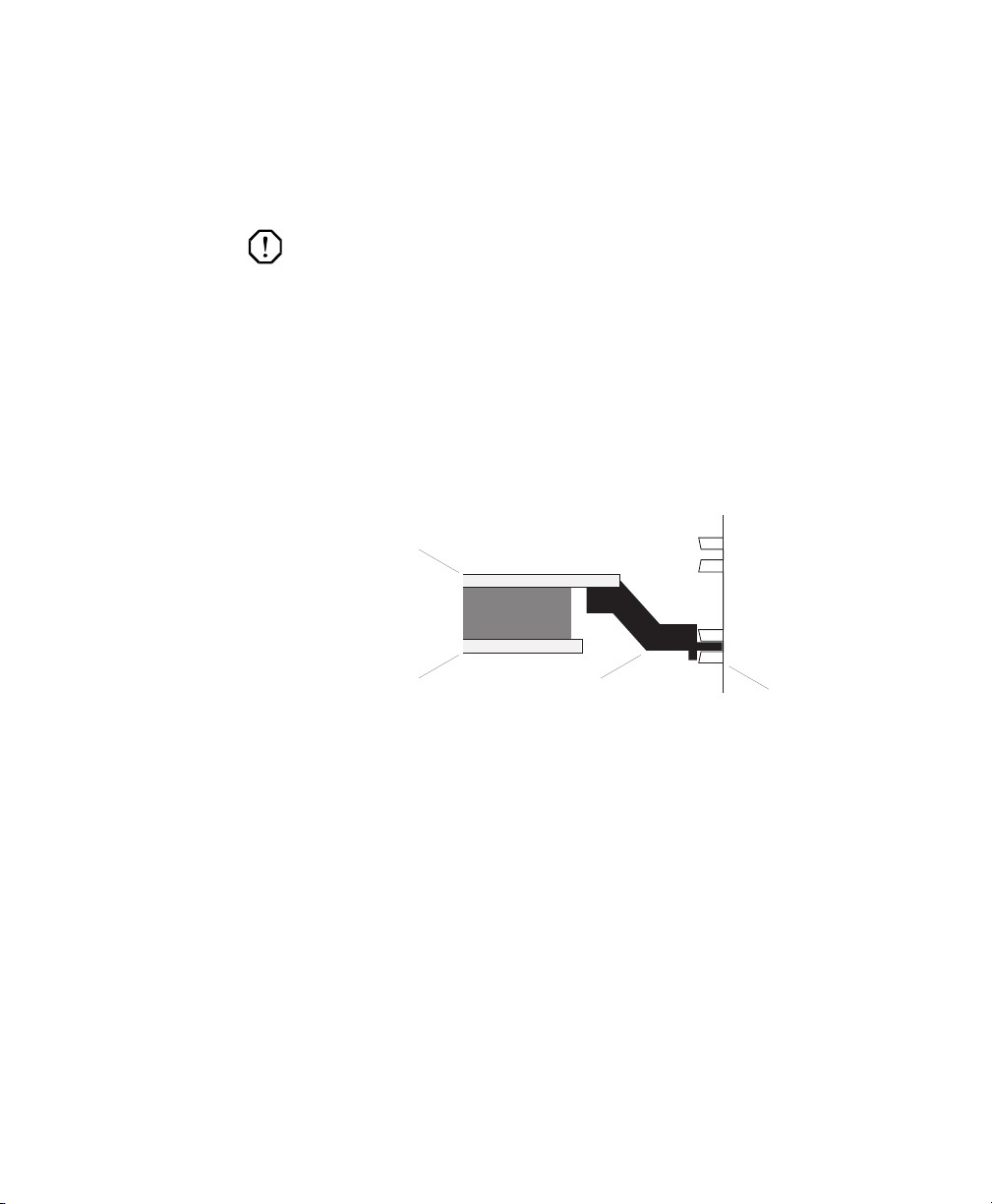
Use the PCI retainer brackets
Almost all computers contain card guides at the front end of the computer
chassis. These help to stabilize cards. Since PCI cards are neither long
enough nor correctly c entered to use these guides, some of the PCI- based
DigiSuite cards ar e equippe d with a PCI r etainer bracke t. The f ollowing
diagram depicts the retainer bracket’s use:
DigiSuite card’s
base board
DigiSuite card’s
module board
Install non-DigiSuite cards first!
It’s important to install any non-DigiSuite cards in y our sy stem befo re
installing your DigiSuite cards. If you don’t do so, your DigiSuite system
may not work properly.
In addition, try to leave em pty slo ts betw een you r Dig iSuite c ard sets
and non-DigiSuite cards if it’s possible. This will permit additional air
flow between cards.
Chapter 2: Hardware Installation
PCI retainer
bracket
ISA card guide
Page 19

Determine your DigiSuite card set order
Each of the following diagrams illustrates the proper placement of
DigiSuite cards with DigiDesktop in your computer system. The
following card combinations are presently available:
1. DigiDesktop (by itself).
2. DigiMix, Di giMotion, and DigiD esktop.
3. DigiLinx , DigiMi x, D igiMotion, Di giDesktop, and G enie.
1. DigiDesktop by itself
DigiDesktop in P3
Back of computer
13
DigiDesktop in P3
DigiMotion in P2
DigiMix in P1
2. DigiMix, DigiMotion, and DigiDesktop
DIG-BUS/MBK
Back of computer
Determine your DigiSuite card set order
Page 20

14
3. DigiLinx, DigiMix, DigiMotion, DigiDesktop, and Genie
Genie in P4
DigiDesktop in P3
DigiMotion in P2
DigiMix in P1
DigiLinx in I2
Back of computer
Installing DigiDesktop by itself
1. Befor e removing DigiD esktop from its pro tective antistatic bag,
place the package within easy reach.
2. Place your computer in the proper installation position.
3. Open your computer and identify the expansion slot you’ll be using.
4. Touch a gray metal part of your computer chas sis in order to drain
static electricity from your body. Use a grounding wrist strap if you
have one.
5. If the slot you choose already contains another PCI card, either move
it to an unused PCI slot or remove it completely
6. Remove the metal plate located at the b ack of the slot. Save the screw ,
as you’ll need it to fasten DigiDesktop after it is inserted.
7. Remov e DigiDesktop fro m its antistatic bag.
8. Carefully align the card with its expansion slot.
9. Slide the card towards the slot until it touches. Make sure that the
metal plate at the back of the card slips into the opening left by the
blank metal plate you removed in step 6 above. In addition, be sure
the PCI retainer bracket is aligned with and inserted into the PCI card
guide inside the front of the computer chassis.
DIG-BUS/LMBKD
Chapter 2: Hardware Installation
Page 21

10. Once the card is aligned, press it into the slot connector until it’s
firmly in place.
11. Secure the card by fastening its metal bracket to the computer chassis
using the screw you re move d in step 6 above.
12. Close y our com pute r co ve r.
13. Y ou are now ready to configure your BIOS setti ngs (see “Configurin g
your system BIOS settings” on page 20).
15
Installing DigiDesktop by itself
Page 22
16
Take care of your Movie-2 bus—Important!
The Movie-2 bus is one of the most important parts in a multi-card
DigiSuite system because it allows for the high-speed audio-video data
transfer between different cards. This speed is required for highperformance digital media systems where professional quality is a must.
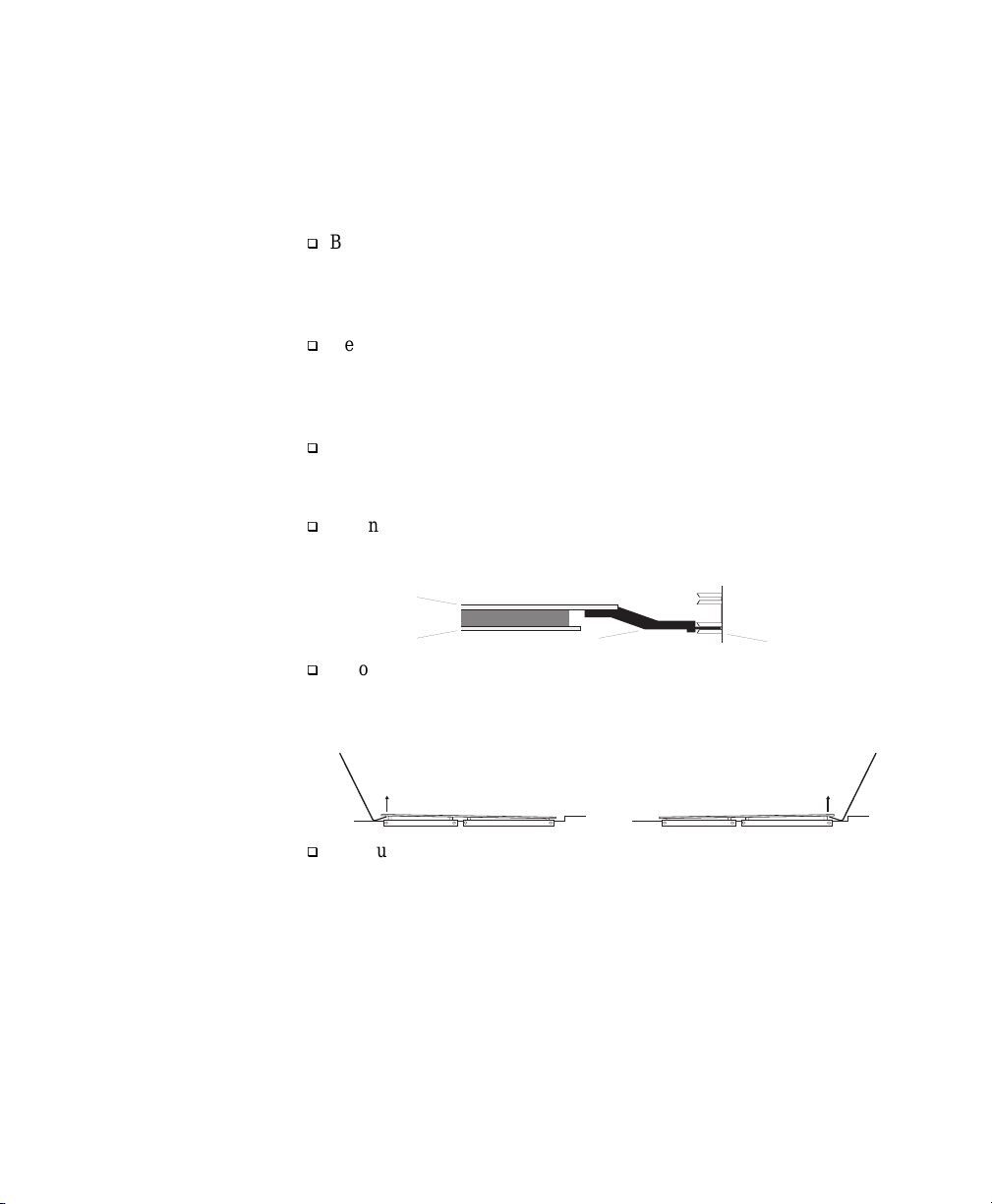
q
Before installing your Movie-2 bus, carefully inspect the connectors
on the bus and on the DigiSuite cards themselves, as well as their
pins. The connectors sh ould no t be cra cke d or bro ken, an d non e of
the pins should be bent or missing.
q
Never force t he parts toge ther! Align t he bus connect or carefully a nd
gently press it into place. When you’re sure the connector is properly
seated, insert the two mounting screws in their holes and turn them
several times with a screwdriver.
q
Do not overtighten the Movie-2 bus mounting screws! Ev en when
the screws are properly tightened, there will be a small space between
the Movie-2 bus circuit board and the top of the cards.
q
When installing or removing y our Mo vie- 2 bu s, b e sure to do so in
a straight motion with no significant lateral angle. Failure to do so
will result in bent pins and/or broken connectors.
DigiSuitecard’s
baseboard
DigiSuitecard’s
moduleboard
q
If you have to remove your Movie-2 bus, use a simple tool to gently
pry it lose at one end — one of the blank metal plates used to cover
an empty computer slot position works well. Then do the same with
the other end of the connector.
q
Although it's possible to install DigiSuite cards in your computer and
then connect the Movie-2 bus to the cards, this method often results
in unreliable connections
individual components as a unit outside y our com pute r, and then
installing the unit as a whole. The following section describes this
procedure for several cards in a system.
1.This is especially so when more than two cards are connected to a bus.
Chapter 2: Hardware Installation
PCIretainer
bracket
1
. We recommend assembling the
ISAcard guide
Page 23

Installing DigiDesktop with other DigiSuite cards
1. Open your computer and identify the expansion slots in which you’ll
install your DigiSuite cards. If any of the required slots already
contain cards, either m ove them to un use d slo ts or rem ove th em
completely.
2. Remov e the metal pla te locate d at th e back of ea ch slot you’ll b e
using. Don’t lose the screws as you’ll need them to fasten the cards
later on.
3. Determine the order of installation for the cards. This is indicated on
the top of the Movie-2 bus. You’ll install the cards from right to left
when facing the back of the computer.
4. Remove each card from its antistatic bag. Y ou should avoid touching
the chips and other components on the circuit boards. Try to handle
the cards by their edges.
5. Set you r termina tion switc h o n DigiM ix. See the DigiMix
Installation Re ference manu al for details.
6. Lay the card to be installed in the rightmost position on its side and
carefully install the Movie-2 bus as shown below. Insert the
mounting screw through the top of the Movie-2 bus and secure it to
the card.
17
Installing DigiDesktop with other DigiSuite cards
Page 24

18
7. Flip the assembled card and Movie-2 bus over with the bus
underneath. Rest the plate end of the card on a flat surface and place
one hand under the Movie-2 bus while installing the second card with
the other hand.
8. Continue supporting the Movie-2 bus with one hand while installing
the third card with the other hand.
Chapter 2: Hardware Installation
Page 25

9. Install the fourth card in the same way.
10. Flip the entire unit over and insert the remaining mounting screws
through the top of the Movie-2 bus. Avoid putting too much stress
on the Movie-2 bus.
11. Carefully install the entire card-bus unit in the intended host
computer, making sure all cards are firmly seated in their slots.
Secure each card’s back plate to the computer.
19
Installing DigiDesktop with other DigiSuite cards
Page 26

20
Configuring your system BIOS settings
For DigiDesktop to function properly as a pa rt of your PCI-ba sed
computer system, you may have to change certain BIOS settings. Th e
BIOS on some PCI systems allows for enabling/disabling of interrupts,
interrupt selection, and enabling/disabling of bus m astering f or
individual slots.
Some newer systems determine the correct settings automatically , so you
need not worry about them. If your system is not automatic, it is essential
that you configure the slot you’ ve chosen for DigiDesktop to the settings
outlined below.
The method for ac c essing th e BIOS settings va ries f rom one sy stem to
another. Please refer to your computer system’s manuals for the correct
procedure.
BIOS settings for Digi De skto p PCI sl ot
PCI Interrupts ..... ... ... ... ... ... .... ... ... ...... ... ... ... ... .... ... ... ... ... ... ... ... ...Enabled
PCI Interrupt number ... ... ... .... ... ... ...... ... ... ... ... .... ... ... ... ... ... ... ... .... ..... Any
Bus mastering ..... ......... ...... ....... ...... ......... ...... ....... ...... ......... .....Disabled
Plug ‘n Play: ...................... .... ... ... ... ... ... ... ... ... .... ... ...... ... ... ... ... ..Disabled
Chapter 2: Hardware Installation
Page 27

Chapter
3
Software Installation and Monitor Setup
This chapter describes how to install the DigiDesktop
software and set up your monitor.
Page 28

22
Display driver installation
You will need to install the display drivers for DigiDesktop before
installing DigiUtils.
Note DigiDesktop is compatible with the Matrox Millennium and
Mystique cards. Whenever you see these names or MGA in the
installation process, you can assume that this applies to your
DigiDesktop card as well.
1. Insert the DigiDesktop Installation CD-ROM in your CD-ROM
drive.
2. Choose
e:\Mga\Nt40\setup
(Where “e:” is the drive letter of your CD-ROM drive.)
and click
3. Select the language you want to use, then click
4. To see notes on the contents of the CD-ROM, click
To continue, click
5. If this is a first-time installation, the setup program lists drivers that
are not installed.
6. To begin the software installation, click
7. Choose an installation type:
– To install the complete MGA PowerDesk (rec omme nded) , click
– To customize the PowerDesk installation, click
If you click
folder and what Powe rDe sk o ptions yo u wa nt to install.
After you choose, the setup program automatically installs the
drivers. After this is done, remove the Matrox CD-ROM from your
CD-ROM drive, then click
Start | Run and type
OK.
Typical.
Next.
View ReadMe.
Next.
Install.
Custom.
Custom, the setup program prompts you for a destination
OK to restart your computer.
For information on configuring your DigiDesktop displa y, see
“Monitor Setup” on page23.
Chapter 3: Software Installation and Monitor Setup
Page 29

Monitor Setup
To che ck your moni tor settings
1. Right-click the Windows desktop backgroun d, click the MGA
Display Properties
2. If you have a Plug-and-Play monitor:
Plug-and-Play (DD C) mon ito r
The
option will automatically be displayed. Make sure that it’s selected.
The MGA display driver will then automatically use the correct
settings for your monitor. If not, click this button, then click
If you don’t have a Plug-and-Play
monitor:
Plug-and-Play (DDC) mo nit or option will be replaced by the
The
Default monitor (60 Hz). You can use this, or the MGA monitor
selection method. For more information on MGA monitor selection,
see the MGA PowerDesk online guide. T o view this document, choose
Start|Pr ograms|MGA NT PowerDesk.
If you have a VESA-compatible monitor:
VESA setti ngs options allows you manually adjust the settings of
The
your VESA-compatible monitor.
Note Many Plug-and-Play monitors do not automatically report whether
they’re capable of 1152 × 864 or higher display resolutions. To use these
resolutions, or higher ref resh ra tes than thos e re por ted by the monito r,
you can use the M GA mo nitor selec tion m eth od.
, then click the Monitor tab.
Apply.
23
Display setup
War ni n g If incorrect software monitor settings are applied, some
monitors can be permanently damaged. For more information, see your
monitor’s manual.
After checking your mon i to r’s software settings, you can change your
display resolution, color palette and other MGA PowerDesk settings.
To access MGA display property sheets, right-click the Windows
desktop background, then click the
item. To change your display resolution or color pa lette, click the
Settings tab. For more information on changing your display settings,
see the MGA PowerDesk online guide. T o view this document, choose
Start|Pr ograms|MGA NT PowerDesk.
MGA Display Properties menu
Monitor Setup
Page 30

24
Important T o display video in a window , you must select a 24-bit color
palette. Be aware that if you select a very high display resolution, you’ll
be able to display a maximum of one video window per monitor.
Installing DigiUtils
For DigiUtils installation, see Chapter 3 of your DigiSuite Installation
Manual.
Important If you already have a DigiUtils version installed, you must
uninstall it before installing DigiUtils version 2.0.0.1019 (which
supports DigiDesktop).
Chapter 3: Software Installation and Monitor Setup
Page 31

Chapter
Configuring DigiDesktop
This chapter explains how to customize your DigiDesktop
card’s configuration to me et specif ic video inpu t and onscreen display requirements.
4
Page 32
26
Starting the configuration program
To start the DigiDesktop configuration prog ram, choo se Start |
Settings | Cont r ol P anel
, then double-click the DigiSuite icon.
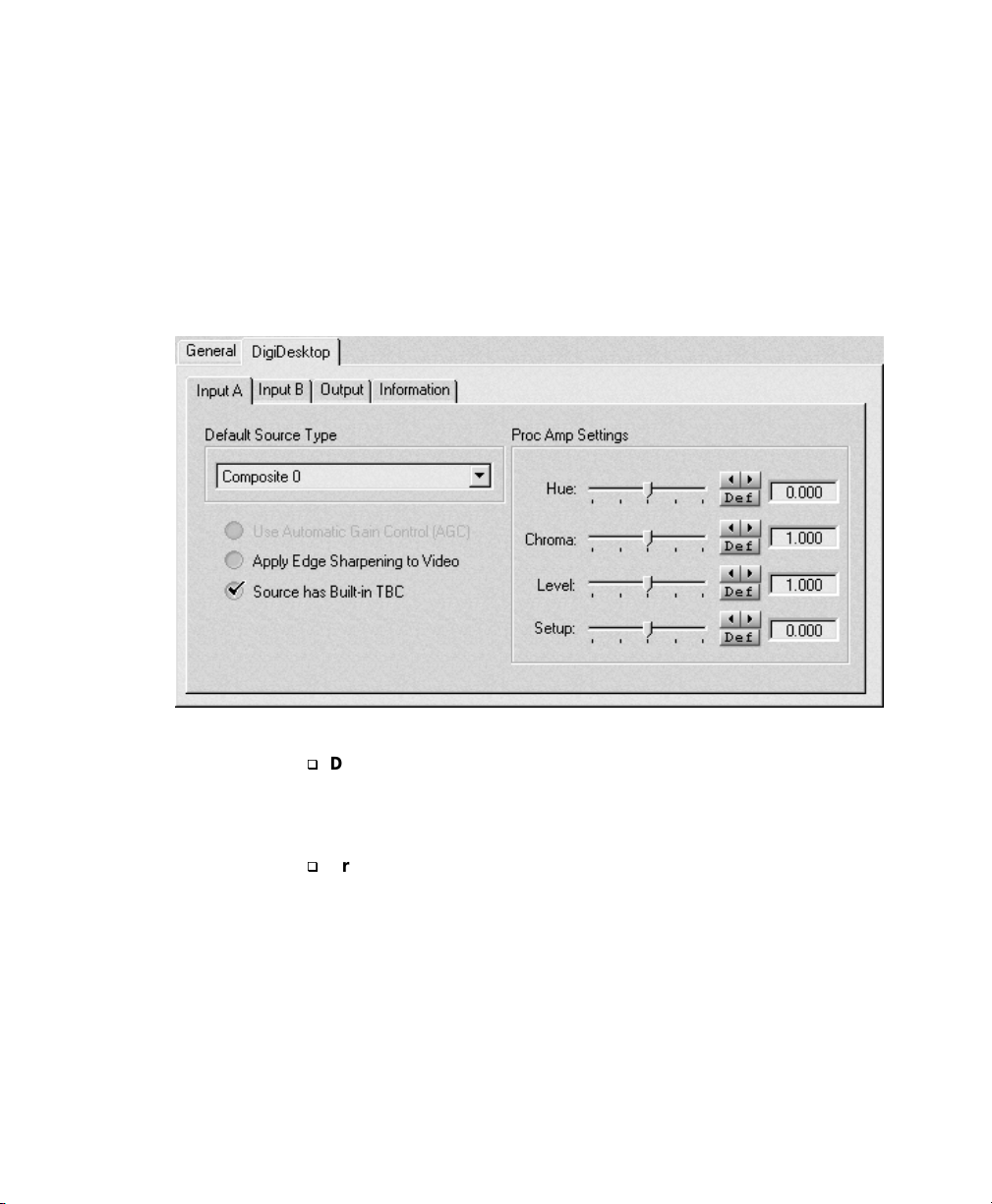
Configuring the video input signals
T o select a de fault vide o s o u rce and configure your vi deo input si gn als,
click the
DigiDesktop tab, then the Input A or Inpu t B tab.
q
Default Source Type Use this list to select which video input to
use from each of the connectors. For example, select
to specify that the Y/C device connected to cable 1 should be the one
used for the specified input source (either Input A or Input B).
q
Proc Amp Settings Use thes e cont rols t o ad just the def ault proc
amps for your incom ing an alog v ideo sign al.
To obtain a precise setting for a control, click its left or right arrow
instead of dragging the slider. T o return a control to its factory default
setting, click its
Hue Adjusts the tint of the colors in the picture.
–
Chroma Adjusts the vividness (saturation) of the picture’s colors.
–
Chapter 4: Configuring DigiDesktop
Y/C (S-Video) 1
Def button or SHI FT+click the slider.
Page 33

–
Level Adjusts the difference in luminance between the lightest
and darkest areas of the picture.
Setup Adjusts the level of black in the picture.
–
q
Use Automatic Gain Control (AGC) Select this option if you want
the gain of your analog input signal to automatically be adjusted to
compensate for very bright or da rk images. Th is improves the
brightness or contrast of y our picture .
Note Despite being shaded on the screen, this option is enabled and
cannot be disabled in this r eleas e.
q
Apply Edge Sharpeni ng t o Video Select this option to slightly
sharpen the edges in your picture (for analog input only). The edge
sharpening is done by amplifying the high frequency component of
the video input's luminance signal. Be aware that selecting this
option may reduce the clarity of fine details in your image.
q
Source has Built -i n TB C Select this option if your analog input
signal is stable and broadcast-quality. This allows DigiDesktop to
use the input signal as is, and therefore to be able to reproduce the
signal precisely without degradation .
If your source device doesn’t have a time base corrector or meet
broadcast-quality standards, make sure this option isn't selected.
DigiDesktop will then filter the signal to increase the tolerance for
sync pulse instability.
27
Configuring the video input signals
Page 34

28
Configuring the video windows
To configure the DigiDesktop on-screen video wi ndows, click the
DigiDesktop tab, then the Output tab.
q
Default Video Sourc e Use this list to assign a p articular video
source to the currently selected video win dow under
Screen 2.
For example, to assign the video source you selected in the
DigiDesktop Input A dialog bo x to windo w #1 on scre en 1 , select
Window #1 under Screen 1, then select Input A from the D efault
Video Source
q
Proc Amp Settings Use these controls to adjust the proc amps of
the currently selected video window. For additional information on
the proc amp controls, se e page 26.
q
Display Video Window To check the effect of making adjustments
to the proc amp settings, select
The video window will be displayed until this dialog box is closed.
The window will automatically appear on the appropriate screen.
That means that if you adjust the proc am p setting for a window on
screen 1, and then sele ct a window on sc reen two, the origina l
Chapter 4: Configuring DigiDesktop
Screen 1 or
list.
Display Video Window.
Page 35

window will disappear from screen 1 and a new one will appear on
screen 2.
Displaying DigiDesktop information
To display system usage and other information about your DigiDesktop,
click the
DigiDesktop tab, then the Information tab.
29
You may be asked to provide this information if you call the Matrox
DigiSuite technical support department for assistan ce.
Displaying DigiDesktop information
Page 36

30
Chapter 4: Configuring DigiDesktop
Page 37

Chapter
Troubleshooting
This chapter provides some possible solutions to
problems you might encounter when installing or
operating DigiDesktop.
5
Page 38

32
Problems and possible solutions
Installation problems
The card does not fit
With a new or previously unused slot, there may be considerable
resistance a s th e ca r d sl id e s in to th e s lo t; ma ke s ure that the ca rd is
perfectly aligned with the PCI slot and push it in firmly but gently until
it is correctly seated.
Your system does not boot
q
Check the list of compatible computers located on the our W eb site at :
http://www .matrox.com/video
You m ay a lso call M atrox Video Products Group Sales at:
800-361-4903 U.S. a nd Cana da
(514) 685-2630 ext. 263 6 Worldwide
q
Make sure your system BIOS se ttings m atch those o utlined in
“Configuring your system BIOS settings” on page 20.
General operating problems
Some or all DigiDesktop fu nc tion s a re not operating
properly
Possible causes
q
The DigiDesktop hardware is improperly installed.
– DigiDesktop must be properly inserted in the appropriate PCI slot.
q
The bracket conn ectors a re n ot pr oper ly c onn ecte d.
– Make sure that all connectors are firmly attached.
q
The driver digiDT.sys is not runnin g.
– To verify this, choose
and check th e s tat u s of th e digiD T.sys driver. If it’s not running,
try the solutions below.
Solutions
q
Ensure that DigiDesktop has its own unique interrupt (if the system
BIOS permits) or e nsure that there are en oug h interr up ts a vaila ble
for each PCI device in the system.
q
You m ust be ru nning Windows NT ver sion 4.0 .
q
If you're using an A LR comp ute r (Ev olution and Revolution
models), all PCI slots in the system must have an interrupt assigned
to them — whether they contain a card or not.
Start | Settings | Control Panel | Devices
Chapter 5: Troubleshooting
Page 39

Random or erratic operating behavior
The components on DigiSuite cards are placed very close together due
to the complex nature of the systems. Electronic components operating
under such condition s g ener ate a con sider able am ou nt of h eat . It is
therefore very important that you provide adequ ate ventilation.
q
Make sure your computer system is well ventilated with no
obstructions blocking any openings, especially at the rear of the unit.
q
Avoid operating a DigiDesktop-equipped computer system in areas
where the temperature is above 86°F (30°C). Do not operate it in
areas with an ambient temperature above 104°F (40°C).
q
Make sure you have at least 32 MB of physical RAM and a 166 MHz
Pentium processor ( or higher ) installe d on y our sy stem.
Two video streams that are not g enlock ed togethe r are be ing played on
the same screen.
q
If you are showing tw o dif f erent vid eo str eams fr om anal og sou rces
on a single screen, make sure that the video sources are both
genlocked to the same sync.
If nothing works!
Contact your Matrox representative. Before doing so, have the following
information ready:
q
A description of what happened.
q
DigiDesktop’s serial number (printed on the car d).
q
As much system information as possible:
– Your computer sp ec ifi cat ions .
– The manufactur er and ve rs ion n um ber o f you r c om puter' s BIOS .
– Windows NT and Service Pack versions.
– Operating environm e nt.
– Peripherals (especially car ds occ upying othe r slots in yo ur
– The information displayed in the Inform ation dial og box of the
q
Anything else you feel will help us correct the problem.
33
computer).
DigiDesktop configuration panel (see “Displaying DigiDesktop
information” on page 29).
If nothing works!
Page 40

34
Chapter 5: Troubleshooting
Page 41

Appendix
A
DigiDesktop Specifications
This appendix provides DigiDesktop hardware
specifications and pin definitions.
Page 42

36
Electrical specifications
Operating voltages and currents
Voltage .............. .... ..... .... ..... .... ..... .... ......... .... ..... .... ..... .... ....+5 V, +12 V, –12 V
Currents................. ..... .... ......... ..... .... ......... .... ..... ......... .... ... 4 A , 150 mA, 0 mA
Video I/O Connectors
Contact resistance........ ..... ......... .... .... ......... ..... .... ..... ......... .... ..... .. 20 mΩ max
Dielectric withstanding voltage ....................... .... ..... ......... .... ......... ..... . 500 V
Insulation resistance ............................... .... ......... ..... .... ......... ..... 100 MΩ min
Movie-2 bus input/output
Digital I/O levels ................. ......... ........ .............. ......... ......... ....TTL compatible
Mechanical specifications
Physical dimensions
12.22" long × 4.50" high × 0.63" wide
(31.04 cm long × 11.43 cm hig h × 1.6 0 c m w ide )
(driven by 74ABT16374A-type registers)
Connector types
Video I/O: Two DB-26 high-density
Movie-2 bus: PSHD090MS0S0
PCI connector for module expa nsion
Environmental specifications
Operating temperature: ........... ......... .... ..... .... .......32°F (0° C) to 104°F (40° C)
Storage temperature: ....... ..... ......... .... .... ......... ..–40°F (–40°C) to 167°F (75° C)
Maximum altitude
for operation: ............................ .... ......... ..... .... ......... .....10,000 ft (3000 m)
for transport: ................ .... ..... ........ ..... .... ......... ..... .... ..40,000 ft (10,000 m)
Humidity: .........................................................................................................
operation: .............................. .... .... ........ 20% to 80% of relative humidit y
storage:........... ..... ......... .... ......... .... ..... ..... 5% to 95% of relative humidity
Appendix A: DigiDesktop Specifications
*
non-condensing
*
*
Page 43

DigiDesktop block diagram
Y
Movie-2 Bus CON 1
37
Frame
Buffer
WRAM 4MB
Frame
Buffer
WRAM 4MB
RAMDAC A
Y/C A0
Y/C A1
/C B0
Y/C B1
Video
Decoder
A
Video
Decoder
B
PreviewI0I1
Main
Digital Input
Crosspoint
Switch
I2
Key Out
VC064S A
MGA-
2064W
A
Movie-2 Bus CON 2
Frame
Trimedia
module
Buffer
WRAM 4MB
Frame
Buffer
WRAM 4MB
RAMDAC B
VC064S B
MGA-
2064W
B
Secondary PCI Bus Interface
PCI to PCI
Bridge
Primary (Host) PCI Bus Interface
DigiDesktop block diagram
Page 44
38
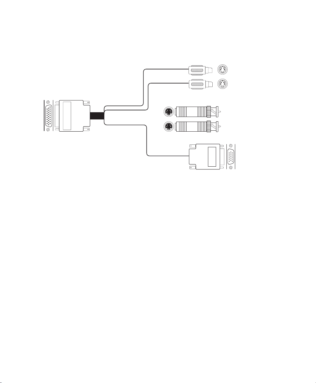
Connector cable overview
T wo DigiDesktop input/output cables (DTOP/IO/CBL) are supplied with
DigiDesktop:
DTOP/IO/CBL
Bracket Connector
Y/C-to-composite
Adaptors
AorB
VGA
Y/C A0 or B0
Y/C A1 or B1
VGA Monitor
Connector
Appendix A: DigiDesktop Specifications
Page 45

Bracket connector (on card)
DB-26 high-density female connector.
39
9
10
26
.
# Signal # Signal
1.
RED_VIDEO
3.
BLUE_VIDEO
5.
MONITOR_ID1 (SDA)
7.
MONITOR_ID2
9.
VCC
11.
GREEN_GND
13.
not connected
15.
Y0_CVBS0_GND
17.
Y1_CVBS1_GND
19.
H_SYNC
21.
V_SYNC
23.
MONITOR_ID0
25.
MONITOR_ID3 ( SCL)
2.
GREEN_VIDEO
4.
GND
6.
Y0_CVBS0
8.
Y1_CVBS1
10.
RED_GND
12.
BLUE_GND
14.
not connected
16.
C0_CVBS2_GND
18.
C1_CVBS3_GND
20.
H_SYNC_GND
22.
V_SYNC_GND
24.
C0_CVBS2
26.
C1_CVBS3
1
18
19
Connector cable overview
Page 46

40
VGA monitor cable output
DB-15 high-density 15-pin female connector.
5
1
610
15
# Signal # Signal
1.
RED_VIDEO
3.
BLUE_VIDEO
5.
GND
7.
GREEN_GND
9.
VCC
11.
MONITOR_ID0
13.
H_SYNC
15.
MONITOR_ID3 ( SCL)
11
2.
GREEN_VIDEO
4.
MONITOR_ID2
6.
RED_GND
8.
BLUE_GND
10.
SYNC_GND
12.
MONITOR_ID1 (SDA)
14.
V_SYNC
Y/C (S-Video) cable input
4-pin mini-DIN male Y/C connector.
3
12
4
# Signal # Signal
1.
LUMA_GND
3.
LUMA
Appendix A: DigiDesktop Specifications
2.
CHROMA_GND
4.
CHROMA
Page 47

Appendix
B
DigiSuite Hardware Glossary
This appendix serves as a reference for the hardware
terminology used in the various DigiSuite manuals.
Page 48

42
Glossary of terms
The following glossary provides basic
definitions of the hardware terminology used in
the DigiSuite documentation. It also explains
distinctions between similar or confusing terms.
A
A/V drive SCSI hard drive capable of storing
high-bandwidth audio/video data.
B
Backplane PCB (printed circuit board) on a
Movie-2 bus connector.
Base board Printed circuit board (and mounted
components such as integrated circuits, etc.) that
is inserted into the computer’s expansion slot. A
module board is often attached to the base board.
BIOS Basic Input/Output System settings for
system components, peripherals, etc. This
information is stored in a special batterypowered memory and is usually accessible for
changes at co m pu ter s tar t-up.
Bus 1. Electrical signal path between different
physical connection points. 2. System bus on
computers, represented by the expansion slot
connectors. 3. Movie-2 bus.
C
Card DigiSuite card as assembled and installed.
For our purposes, a card is the final assembled
product, whereas a board is simply one the of the
printed circuit boards that make up a card.
Card set One or more DigiSuite cards
recognized by DigiSuite software as a single
functional unit. If a card set contains two or more
cards, these are connected by a Movie-2 bus.
There may be more than one card set connected
by a Movie-2 bus connector.
CON 1 and CON 2 1. Male connectors (usually
with 90 or 70 pins) mounted at the top of a
DigiSuite card c losest to the center o f the card.
2. Their female counterpart on a Movie-2 bus.
Connector set Combination of the Movie-2 bus
connectors CON 1 and 2 on a DigiSuite card and/
or a Movie-2 bus.
E
EISA slot Connection slot to a type of computer
expansion bus found in some computers. EISA
is an extended version of the standard ISA slot
design.
Expansion slot Electrical connection slot
mounted on a computer’s motherboard (main
circuit board). It allows several peripheral
devices to be connected inside a computer.
H
Host bus Computer syst em bus to whi ch a
DigiSuite card is connected by insertion in the
appropriate slot. This will be either a PCI, an
EISA, or an ISA bus.
I
ISA slot Connection slot to a type of computer
expansion bus found in most computers. It’s
larger in size than the PCI slots found on mos t
Pentium-based computers and provides
connections to the slower ISA bus. A variation
found in some newer computers is the EISA bus.
M
Module board Printed circuit board and
mounted components that is attached to the base
board using screws and spacers.
Movie-2 bus or Movie-2 bus connector Over-
the-top connector used for high-speed data
transfer. These two terms refer to the assembled
component, which consists of a printed circuit
board (backplane) with attached connectors.
Appendix B: DigiSuite Hardware Glossary
Page 49

P
PCI retainer bracket Bracket attached to
DigiSuite PCI cards with the function of
extending their length to line up with and be
inserted in standard ISA card guides.
PCI slot Connection slot to a type of expansion
bus found in most Pentium-based computers. It
is smaller in s ize t han ol der ISA s lots and
provides connections to the high-speed PCI host
bus.
43
Page 50

44
Appendix B: DigiSuite Hardware Glossary
Page 51

Appendix
Technical Support
This appendix explains how to reach us to obtain
technical support.
C
Page 52

46
DigiDesktop technical support
If you have a problem or question that you’re unable to solve by referring
to your DigiDesktop doc um entation, p lea se c ontact you r Ma tro x
DigiDesktop dealer. He or she should be able to help you quickly correct
any installation or s ystem con figuration p rob lem .
Contacting us by voice, fax, or Emaill
If your dealer is unable to solve your problem, you may contact Matrox
for further information and assistance.
Telepho ne U.S . & Canada.. ....... ... ... ... ... ... ...... .... ... ... ... ... .(800) 810-2550
Telepho ne Worldwi de... ... ... .... ... ...... ... ... ... ... ... . (514) 685-2630 ext. 2388
Fax .................................................................................(514) 685-2853
Email ..................... ................. video.digisuite.techsupport@matrox.com
World Wide Web
W e also invite you to visit our W orld W ide W eb site for up-to-the-minute
information about Matrox products, fre e driver upd ates, an swers to
frequently asked que stions (FAQs), and a complete list o f com pat ible
computers and mo t herbo ar ds .
Internet ..... .... ... ... ... ... ... ... ... .... ... ... ... ... ... ... ... ... ....www.matrox.com/video/
Driver updates by FTP or BBS
Free driver updates can also be obtained from our F TP site or the Matrox
BBS.
FTP site................. ... ... ...... .... ... ... ... ... ... ...... ... . ftp.matrox.com/pub/video
Matrox BBS ........ ... ... ... ... ... .... ... ... ... ... ... ...... ... .... ... ... ... ... .(514) 969-6244
BBS U.S. & Canada............... ... ...... ... ... ... ... ... .... ... ... ... ... .(514) 969-6244
BBS France ................. ... ... .... ... ... ...... ... ... ... ... .... ...+33 (0) 1 45 6 0 62 08
BBS Germany.. ... ... ... ... ... ... .... ... ... ... ... ...... ... ... .... ... .+49 (0) 89 6 14 00 91
BBS U.K. ............... ... ... ... ... .... ... ... ... ... ... ... ...... .... ... +44 (0 ) 1 793 489906
Appendix C: Technical Support
Page 53

Index
47
A
Accessories 5
AGC 27
ALR computers 32
Apply Edge Sharpeni ng 27
Automatic gain control 27
B
BBS 46
BIOS settings 20
Block diagram 37
Bracket connector 39
C
Card order
DigiLinx, DigiMix, DigiMotion, DigiDesk -
top, Genie 14
DigiMix, DigiMotion, DigiDe sktop 13
Chroma control 26
Configuration 25
Configuring
information 29
output signals 28
video input signals 26
Customer support
See Technical support 46
D
DDC monitor 23
DigiSuite
compatible computers list 9
hardware glossary 42
Display settings 23
Documentation 3
Drivers
getting updates 46
installation 22
troubleshooting 32
E
Edge Sharpening 27
Expansion slots 11
F
FTP 46
H
Hardware installation 7
Hue control 26
I
Input
automatic gain control 27
default source type 26
edge sharpening 27
proc amp settings 26
TBC 27
Installation
card order 13
DigiDesktop by itself 13
DigiSuite cards 17
drivers 22
expansion slots 11
hardware 7
problems 32
proper position 10
safety precautions 8
software 21
summary 9
Internet
Matrox WWW, FTP, and BB S 46
ISA slots 11
L
Level control 27
Index
Page 54

48
M
Matrox
contacting 46
Movie-2 bus
avoiding damage 16
See also Card order 13
O
Output 28
default source 28
display video window 28
P
PCI
retainer bracket 12
PCI slot
card does no t fi t 32
identifying 11
Pin definitions
Bracket connector 39
VGA monitor cable output 40
Y/C cable in put 40
Plug-and-Play
BIOS settings 20
monitor 23
PCI slot 20
Proc amp settings 26
chroma control 26
level control 27
setup control 27
T
TBC 27
Technical su ppo rt 45, 46
Troubleshooting 31
getting updated information 46
installation problems 32
V
VESA 23
VGA monitor cable output 40
Video input signals 26
W
WWW 46
Y
Y/C cable input 40
S
Setup control 27
Single-card installation 13
Software installation 21
Specifications 35
electrical 36
environmental 36
mechanical 36
S-Video cable input 40
System requirements 2
Index
Page 55

Page 56

Corporate Headquarters
Matrox Electronic Systems Ltd.
Video Products Group
1055 St. Regis Blvd.
Dorval, Quebec
Canada H9P 2T4
Telephone: (514) 685-2630
Fax: (514) 685-2853
BBS: (514) 969-6244
United Kingdom
Matrox (UK) Ltd.
6 Cherry Orchard West
Kembrey Park, Swindon
England SN2 6UP
Telephone: 01793.441.100
Fax: 01793.441.199
BBS: 01793.489.906
France
Matrox France SARL
6, rue de la Couture
Silic 225
94528 Rungis Cedex
Telephone: (33) 1.45.60.62.00
Fax: (33) 1.45.60.62.05
BBS: (33) 1.45.60.62.08
Germany
Matrox Electronic Systems GmbH
Inselkammerstraße 8
D-82008 Unterhaching bei
München, Germany
Telephone: 089 614 474-0
Fax: 089 614 97 43
BBS: 089 614 00 91
Pacific-Asia
Matrox Asia Liaison Office
Room 1901, 19/F
Workington Tower
78 Bonham Strand E.
Sheung Wan, Hong Kong
Telephone: 852-2877-5387
Fax: 852-2537-9530
 Loading...