

Page 1

InterServe 9400
System Setup
May 1999
D5AA00070
Page 2

Copyright
1999 Intergraph Computer Systems. All rights reserved. This document contains information protected by copyright, trade secret,
and trademark law. This document may not, in whole or in part, be reproduced in any form or by any means, or be used to make any
derivative work, without written consent from Intergraph Computer Systems.
Use, duplication, or disclosure by the United States Government is subject to restrictions as set forth in subdivision (c)(1)(ii) of the
rights in technical data and computer software clause at DFARS 252.227-7013. Unpublished rights are reserved under the copyright
laws of the United States.
Intergraph Computer Systems, Huntsville AL 35894-0001
Notice
Information in this document is subject to change without notice and should not be considered a commitment by Intergraph Computer
Systems. Intergraph Computer Systems shall not be liable for technical or editorial errors in, or omissions from, this document.
Intergraph Computer Systems shall not be liable for incidental or consequential damages resulting from the furnishing or use of this
document.
All warranties given by Intergraph Computer Systems about equipment or software are set forth in your purchase contract. Nothing
stated in, or implied by, this document or its contents shall be considered or deemed a modification or amendment of such warranties.
Trademarks
Intergraph Computer Systems and the Intergraph Computer Systems logo are registered trademarks of Intergraph Computer Systems.
InterServe is a trademark of Intergraph Computer Systems.
Other brands and product names are trademarks of their respective owners.
FCC/DOC Compliance
This equipment has been tested and found to comply with the limits for a Class A digital device, pursuant to part 15 of the FCC
Rules. These limits are desi gned to provide rea sonable protection against harmful int er ference when the equipment is op erated in a
commercial environment. This equipment generates, uses, and can radiate radio frequency energy, and if not installed and used in
accordance with the instruction manual, may cause harmful interfrence to radio communications
This digital apparatus does not exceed the Class A limits for radio noise emissions from digital apparatus set out in the Radio
Interference Regulations of the Canadian Department of Communications.
Warnings
The service and upgrade instructions should be performed by qualified personnel only. Qualified personnel do not have to be
Intergraph service personnel. Those who are familiar with servicing computers can follow instructions in a manual to service
equipment, and do so without harm to themselves or damage to the equipment.
Changes or modifications made to the system that are not approved by the party responsible for compliance could void the user’s
authority to operate the equipment.
To reduce the risk of electrical shock, do not attempt to open the equipment unless instructed. Do not use a tool for purposes other
than instructed.
There is a danger of explosion if the battery is incorrectly replaced. Replace the battery only with the same or equivalent type as
recommended by the manufacturer. Dispose of used batteries according to the manufacturer’s instructions.
To comply with FCC Class A limits, you must use shielded cables with this device.
Notes
Read all operating instructions before using this device. Keep these instructions for future reference. Follow all warnings on the
device or in the operating instructions. This device is designed and manufactured to comply with approved safety standards for
information processing and business equipment.
Page 3

Contents
Preface............................................................................................................................................. v
About This Document...................................................................................................................... v
Document Conventions .................................................................................................................... v
Operating System Information.......................................................................................................... v
Hardware Information..................................................................................................................... vi
Ergonomic Information ................................................................................................................... vi
Customer Support............................................................................................................................ vi
1 Setting Up the Hardware............................................................................................................ 1
Before You Begin............................................................................................................................. 2
Unpacking the Equipment ................................................................................................................ 2
Selecting a Site for the System......................................................................................................... 3
Setting Up the Rack-mount System.................................................................................................. 4
Connecting the Cables .................................................................................................................... 11
Checking the System ...................................................................................................................... 13
What’s Next? .................................................................................................................................. 13
iii
Hardware and Software Support Services......................................................................... vi
World Wide Web............................................................................................................. vii
Intergraph Bulletin Board Service....................................................................................vii
Telephone......................................................................................................................... vii
More Support Options..................................................................................................... viii
Safety Guidelines...............................................................................................................4
Installing the System Into a Rack....................................................................................... 5
2 Setting Up the Software............................................................................................................ 15
Preparing for Setup......................................................................................................................... 16
Pre-Installed Software ...................................................................................................... 16
Before You Start Setup .................................................................................................... 16
Starting the System......................................................................................................................... 18
Starting Operating System Setup.................................................................................................... 18
Finishing Operating System Setup..................................................................................................19
Creating an Emergency Repair Disk................................................................................ 19
Creating System Software Backup Diskettes ................................................................... 19
What’s Next? .................................................................................................................................. 20
3 Configuring the System............................................................................................................. 21
Configuring the Video Display....................................................................................................... 22
Changing the Default Video Display Driver.................................................................... 22
Correcting Video Display Problems................................................................................. 22
Installing and Configuring LanSafe UPS Software ........................................................................ 23
Installing QFE Update Software..................................................................................................... 24
Installing Software for InterSite Server Monitor II ........................................................................ 24
Creating an Emergency Repair Disk...............................................................................................24
Getting Operating System Updates................................................................................................. 25
Page 4

iv
4 Operating Notes......................................................................................................................... 27
Starting and Stopping the System................................................................................................... 28
System Status LEDs ....................................................................................................................... 30
Disk Drive Status LEDs (RAID Systems)...................................................................................... 30
System Alert................................................................................................................................... 30
Using InterSite Programs................................................................................................................31
Additional User Information........................................................................................................... 31
What’s Next? .................................................................................................................................. 32
5 Reinstalling System Software................................................................................................... 33
Before You Begin........................................................................................................................... 34
System Software Products.............................................................................................................. 34
Installing Windows NT Server 4.0 on Systems with 3 GB of Memory or Less ............................. 36
Installing Windows NT Server 4.0 on Systems with More Than 3 GB of Memory....................... 37
Getting Operating System Updates................................................................................................. 39
Returned Goods Authorization (RGA) Form
Warranty Procedure
Repair Depot Address Labels
Page 5

Preface
InterServe 9400 System Setup describes setting up, configuring, and operating your InterServe
9400 system.
About This Document
InterServe 9400 System Setup is organized as follows:
♦ Chapter 1, “Setting Up the Hardware,” describes how to set up the system hardware.
♦ Chapter 2, “Setting Up the Software,” describes how to set up the operating system and
associated system software.
♦ Chapter 3, “Configuring the System,” describes how to configure the system for use.
♦ Chapter 4, “Operating Notes,” describes how to use essential system features and provides
other important information.
♦ Chapter 5, “Reinstalling System Software,” describes how to reinstall the operating system
and associated system software, if required.
v
Document Conventions
Bold
Italic Variable values that you supply, or cross-references.
Monospace
SMALL CAPS Key names on the keyboard, such as D, ALT or F3; names of files and
CTRL+D Press a key while simultaneously pressing another key; for example, press
Commands, words, or characters that you key in literally.
Output displayed on the screen.
directories. You can type filenames and directory names in the dialog boxes
or the command line in lowercase unless directed otherwise.
CTRL and D simultaneously.
Operating System Information
For more detailed information on the operating system, see the printed and online Microsoft
documentation delivered with the system.
See the Late-Breaking News shipped with your system for important software and documentation
information not covered in this document.
Page 6

vi
Hardware Information
Detailed reference information for your new system is provided in the System Reference, which
covers user and service technician subjects such as the following:
Part I, User’s Guide:
♦ System introduction
♦ Installation
♦ Set-up utilities
♦ Hot-swap hard disk drives, power supplies, and fans
Part II, Service Technician’s Guide:
♦ Removing/reinstalling server components
♦ PHP I/O baseboard: de scription and setting configuration jumpers
♦ CPU baseboard: descriptio n and setting configuration jumpers
♦ Power system
♦ Back-up battery
♦ Memory modules
♦ Solving problems
See the Late-Breaking News shipped with your system for important hardware and documentation
details not covered in this document.
Ergonomic Information
Read the Ergonomics Guide delivered with your system for valuable information on ways to
minimize repetitive stress injuries when working with a computer.
Customer Support
Intergraph Computer Systems offers an assortment of customer support options.
Hardware and Software Support Services
Intergraph Computer Systems provides a variety of hardware services for Intergraph and thirdparty equipment. Services include warranty upgrades, repair depot service, on-site hardware
Page 7

maintenance, system administration, and network co nsulting. Hardware purchased fro m Inter graph
Computer Systems includes a factory warranty ranging from 30 days to three years. A detailed
warranty description is available on the World Wide Web; see the Support pages at
http://www.intergraph.com/ics.
Intergraph Computer Systems provides complimentary software support for 30 or 90 days
following shipment of a hardware or software product. This includes World Wide Web access,
Intergraph Bulletin Board Service access, and telephone (Help Desk) support. At the end of the
complimentary support period, you can purchase other levels of software support.
World Wide Web
You can visit Intergraph Computer Systems on the World Wide Web at
http://www.intergraph.com/ics. On these pages, you can get news and product information,
technical support information, software updates and fixes, and more.
Intergraph Bulletin Board Service
On the Intergraph Bulletin Board Service (IBBS), you can get technical support information,
software updates and fixes, and more.
vii
To connect to the IBBS:
1. Set your system’s communications protocol for eight (8) data bits, no parity, one (1) stop bit,
2. Using a modem, call 1-256-730-8786. Outside the United States, call one of the mirror sites
3. At the login prompt, key in your user ID. If you have not connected before, key in new to
4. Follow the menus to find what you need. The IBBS provides clear choices and online help.
If you have trouble conne cting to or using the IBBS, call the Customer Response Center at
1-800-633-7248 (product entry IBBS) or leave a message for the IBBS System Operator at
1-256-730-1413.
Telephone
To get customer support by telephone:
♦ In the United States, call 1-800-633-7248 between the hours of 7:00 a.m. and
♦ Outside the United States, contact your local Intergraph Computer Systems subsidiary or
and any baud rate up to 14,400.
listed on World Wide Web; see the Software Support pages at http://www.intergraph.com.
create a user ID.
7:00 p.m. Central Time, Monday through Friday (except holidays).
distributor.
Page 8

viii
Have the following information available when you call:
♦ Your service number, which identifies your site to Intergraph Computer Systems. You use
your service number for warranty or maintena nce calls.
♦ Your Customer Personal Identification Number (CPIN). You get a CPIN the first time you
call the Customer Response Center; it is associated with your service number for future call
logging.
♦ The product’s name or model number.
♦ The product’s serial number. Software product serial numbers are included in the product
packaging. Hardware product serial numbers are on a sticker affixed to the hardware product.
♦ Your name and telephone number.
♦ A brief description of the question or problem.
More Support Options
To get information on more customer support options:
♦ Visit the Support pages on the World Wide Web at http://www.intergraph.com/ics.
♦ For hardware support questions in the United States, call 1-800-763-0242.
♦ For software support questions in the United States, call 1-800-345-4856.
♦ Outside the United States, contact your local Intergraph Computer Systems subsidiary or
distributor.
Page 9

1 Setting Up the Hardware
Follow the instructions in this chapter to set up an InterServe 9400 in a stand-alone deskside
configuration or to set up and install it into an Intergraph equipment rack.
Before You Begin............................................................................................................................. 2
Unpacking the Equipment ................................................................................................................ 2
Selecting a Site for the System......................................................................................................... 3
Setting Up the Rack-mount System.................................................................................................. 4
Safety Guidelines...............................................................................................................4
Installing the System Into a Rack....................................................................................... 5
Connecting the Cables .................................................................................................................... 11
Checking the System ...................................................................................................................... 13
What’s Next? .................................................................................................................................. 13
1
Page 10

2
Before You Begin
Read this chapter before you attempt to set up an InterServe 9400. In addition:
♦ Contact the local Intergraph support office if any items you ordered are missing or damaged.
♦ If you use non-Intergraph cables with the system, ensure that they are shielded and terminated
on both ends. Intergraph-supplied cables are shielded to prevent excessive electromagnetic
interference (EMI).
♦ If using an external power source with your system, such as an AC distribution box or an
uninterruptible power supply (UPS), review the documentation delivered with the power
source for information about its capabilities.
♦ If you need to return equipment for repair, you must ship it in Intergraph-supplied packaging
to get warranty service.
♦ Follow the installation instructions carefully to avoid personal injury and damage to the
system hardware.
If you are installing the system into a rack, note the following.
♦ Set up the Intergraph rack using the documentation delivered with the rack. Become familiar
with the rack enclosure before installing the system hardware into it.
♦ Do not push on or lean against the rack.
♦ The rack’s front and side stabilizer feet must be extended at all times.
Unpacking the Equipment
The InterServe 9400 is shipped in 3 corrugated boxes strapped to a pallet. The contents of the
boxes are as follows:
♦ System box—Contains the InterServe 9400 base unit (see the following figure).
♦ Parts box—Contains the keyboard, mouse, and key (for the drive access door); Windows NT
Server operating system (compact disks, floppy diskettes, and documentation), if ordered;
Intergraph system software (diskettes); label sheets for disk drives; and documentation.
♦ Rack rail box—Contains rack rails and associated hardware for rack-mount installation.
Hard disks (two system drives) will be installed in the system.
If you ordered a monitor from Intergraph Computer Systems, it is shipped separately from the base
unit pallet. Its carton contains the monitor, the monitor AC power cord, the video cable, and
monitor documentation.
Page 11

NOTE If any of the listed items were not delivered, call the Customer Response Center
immediately at 1-800-633-7248.
Save all packaging materials after setting up the system. If you return equipment for repair, it must
be in its original packaging for you to get warranty service (if provided under your contract
agreement).
IS9400 Base Unit
3
Selecting a Site for the System
Operation of the InterServe 9400 system at conditions beyond those shown in the following table
may cause permanent damage to the system. Exposure to conditions outside the absolute
maximum ratings for extended periods may affect system reliability.
The following table provides the absolute maximum conditions.
Condition
Operating temperature 0° C to +40° C
Storage temperature -55° C to +150° C
Voltage on any signal with respect to ground
3.3 V supply voltage with respect to ground -0.3 V to +3.63 V
5 V supply voltage with respect to ground -0.3 V to +5.5 V
12 V supply voltage with respect to ground -0.3 V to +12.6 V
-12 V supply voltage with respect to ground -13.2 V to +0.3 V
* V
= supply voltage for the device.
DD
Range
-0.3 V to *V
+ 0.3 V
DD
Page 12

4
The InterServe 9400 installs in a rack. Before you set up your system, determine where you want
to place it. Keep these guidelines in mind:
♦ Place the system as close as possible to the proper power outlet. The power cord connecting
the system to the facility power outlet or other power source serves as the disconnect device.
♦ Place the system in an area where air can circulate freely around it.
♦ Do not expose the system to high levels of dust, smoke, or moisture.
♦ Place the system in an area where the temperature range stays between 10° C and 26° C (50° F
and 80° F). The optimum operating temperature is 21° C (70° F).
♦ Place the system in an area where the humidity stays between 20 percent and 80 percent (non-
condensing). The optimum operating humidity is 50 percent (non-condensing).
Setting Up the Rack-mount System
This section explains how to install a rack-mount InterServe 9400 system in a 19-inch Intergraph
17 U, 21 U, or 40 U equipment rack. Only technically qualified personnel should install the
system. Computer equipment is secured in the rack along the mounting posts using 7.1 mm
diameter mounting holes. The mounting posts have small round markers to designate each U.
There are three mounting holes per U.
The sizes of racks are designated by their available vertical height and width. Knowing the size of
the rack and the size of the equipment you are installing in it helps determine if the rack is capable
of containing the equipment.
NOTE Physical space is not the only factor to consider when installing equipment. There
are facility and power requirements and load limitations to observe. For more
information about power requirements and load limitations, see the documentation
delivered with the system and equipment.
Safety Guidelines
Before you set up a system, please read and observe the following safety guidelines:
WARNING Avoid injury. The minimum system configuration weighs 51.4 kg (113 lbs), and
the maximum weighs 60 kg (132 lbs). To avoid injury, two people should lift
and insert the system into the slide assemblies in the equipment rack.
WARNING Work on only one system at a time. Extend only one system at a time from the
equipment rack. Extending more than one system can result in the rack tipping
forward on you.
Page 13

WARNING Anchor the equipment rack. The equipment rack must be anchored to an
unmovable support to prevent it from falling over when a system on slide
assemblies is extended in front of it. The anchors must be able to withstand a
force of up to 113 kg (250 lbs). You must also consider the weight of any other
device installed in the rack.
WARNING Install a main AC power disconnect. You are responsible for installing an AC
power disconnect for the entire rack unit. This main disconnect must be
readily accessible, and it must be labeled as controlling power to the entire
unit, not just to the system(s).
WARNING Ground the rack installation. To avoid the potential for an electrical shock
hazard, you must include a third wire safety grounding conductor with the rack
installation. If system power cords are plugged into AC outlets that are part of
the rack, then you must provide proper grounding for the rack itself. If system
power cords are plugged into wall AC outlets, the safety grounding conductor
in each power cord provides proper grounding only for the system. You must
provide additional, proper grounding for the rack and for other devices
installed in it.
WARNING Protect against overcurrent. The system is designed for an AC line voltage
source with up to 20 amperes of overcurrent protection. If the power system
for the equipment rack is installed on a branch circuit with more than 20
amperes of protection, you must provide supplemental protection for the
system. If more than one system is installed in the rack, the power source for
each system must be from a separate branch circuit. The overall current rating
of a system configured with three power supplies is under 12 amperes.
5
CAUTION Temperature. The operating temperature of the system, when installed in an
equipment rack, must not go below 5° C (41° F) or rise above 35° C (95° F).
Extreme fluctuations in temperature can cause a variety of problems in your system.
CAUTION Ventilation. The equipment rack must provide sufficient airflow to the front of the
system to maintain proper cooling. It must also include ventilation sufficient to
exhaust a minimum of 3,150 Btu's per hour for the system. The rack selected and
the ventilation provided must be suitable to the environment in which the system will
be used.
Installing the System Into a Rack
You will need the following tools:
♦ Phillips screwdrivers, #1 and #2
♦ Pencil
Page 14

6
Before installing the system into a 19-inch equipment rack, you must attach the slide rails and
mounting brackets to the rack as instructed in this section. Perform the following steps carefully;
the mounting brackets must be installed with precision to allow room for the next system you
install in a rack.
NOTE A total of two mounting brackets attach to the vertical rails of the equipment rack.
To mark the hole spacing on the vertical rails:
1. See the following figure for a view of the vertical rail and the hole spacing details. The
vertical rails of the 17 U, 21 U, and 40 U racks have a hole between every 1 U, and a square
between every 4 U. All dimensions are in millimeters
2. With a pencil, mark the top and bottom hole locations for the mounting brackets on both side s
of the vertical rails.
1 U Marker
To attach the mounting brackets to the vertical rails and install the system:
1. Before installing the slide rails, remove the rear EIA brackets from each of the rails shipped
with the InterServe 9400. Turn each bracket 180 degrees and install each on the end of the
opposite rail as shown in the following figure, but do not tighten the brackets. This allows the
brackets to line up with the appropriate mounting holes on the rear vertical rails of the rack.
CAUTION Note that each bracket has two open slots that will slide over the mounting screws
between rail and bar nut. Unless the rear brackets are removed, rotated, and
installed on the opposite slide rail, the open slots will not line up for proper
installation.
Rear EIA Bracket (on each slide rail)
Page 15

2. Temporarily secure bar nuts to the rack rails using the second and fifth holes.
3. Place the slide rails by sliding the two open slots of the EIA brackets over the screws in
between the bar nut and the rack vertical rails.
4. Fasten all four screws in both front and back.
5. Tighten the rear brackets.
7
Page 16

8
6. Using the screws and nuts provided, attach the slide assemblies on the rack.
A
A. Slide assembly front
B. Slide assembly rear
B
OM07362
Page 17

7. Fully extend the slide assemblies until they lock into place.
8. Lower the system onto the side assembly tabs. The tabs install into the slots on the system.
A
9
A. Slide assembly tabs
B. System tab slots
B
OM07363
Page 18

10
9. Secure each slide assembly to the system with three provided screws.
10. Unlock the slide assemblies by pressing outward on each locking tab and push the system into
the rack.
A
OM07364
To attach the chassis handles:
1. Remove the handles, hangers, and screws (#10-32 x .187 flat head) from the parts box. Attach
the handles to the hangers as shown in the following figure.
2. Orient each hanger so the two screw holes on the long edge of each handle align with the
threaded holes in the faceplate. The hangers can be installed in only one way.
3. Use four screws to attach the hangers (two per hanger) to the faceplate.
Page 19

Connecting the Cables
All cable ports on the base unit and other Intergraph equipment are keyed or molded and clearly
labeled to ensure proper cable attachment. If a cable is not attaching easily, ensure that you are
aligning the cable connector correctly with the port.
To connect the cables:
Connect the necessary cables to the appropriate ports on the I/O panel on the rear of the system, as
follows:
11
Connect the cable from…
Keyboard (PS/2) Keyboard port on server I/O panel
Mouse (PS/2) Mouse port on server I/O panel
Monitor (Super VGA) Video Out port on server I/O panel
Printer or other parallel device Parallel port on server I/O panel
Serial device Serial port on server I/O panel
USB device USB port on server I/O panel
LVDS SCSI device LVDS SCSI port on server I/O panel
See the following figure for port locations.
To…
Page 20

12
A CB
D
E
F
N
G
H
I
M
J
L
K
OM07300
A. PCI and ISA add-in board expansion slots
B. External LVDS connector
C. PS/2-compatible keyboard/mouse port, 6-pin
D. PS/2-compatible keyboard/mouse port, 6-pin
E. PS/2-compatible serial ports 0 and 1, 9-pin RS-232 connector
F. Super VGA compatible, 15-pin video connector
G. P S/2 -compatible pa rallel port (LPT), 25-pin bidirectional subminiature D connector
H. USB ports 0 and 1, 4-pin connector
I. Intelligent Chassis Management Bus (ICMB) connectors port 1 and 2
J. Power supplies
K. Failure LED (yellow)
L. Pr ed ictive failure LED (yellow) for power supply fan
M. Power LED (green)
N. AC input power connector
Page 21

Checking the System
Before starting the rack-mount system, review the following items:
♦ All hardware is properly and securely installed in the rack.
♦ The cables are properly attached from the base unit to the accessories installed in the rack or
in remote locations.
♦ The cables attached to the server base unit are routed through the cable handler. Ensure there
is enough cable service loop to allow sliding devices to extend 31 inches.
♦ The cables that run along the sides or top of the rack are installed in clips or ties to secure
them in place.
♦ All disk drives are installed in the proper slots and labeled appropriately.
♦ The base unit is retracted into the rack.
♦ The power cord from the AC distribution box or UPS is attached to the correct power outlet.
WARNING Once you install the equipment into the rack, do not move the rack. If you must
move it, first remove all equipment, move the rack to its new location, and then
reinstall the equipment.
13
What’s Next?
You can do any of the following to prepare your system for use:
♦ To use Intergraph’s default setup, go to Chapter 2, “Setting Up the Hardware,” to start the
system and go through Windows NT Setup. If you start the system, and then turn it off before
completing the instructions in Chapter 2, you will have to reload the operating system and
system software.
♦ Intergraph Computer Systems installs the operating system through P hase 1 of the Windows
NT Setup process. Phase 2 involves establishing a domain name, determining a security role,
and setting up user accounts. If you want to reinstall the operating system and system
software, instead of completing Phase 2 of Setup, refer to Chapter 5, “Reinstalling System
Software.”
Page 22

14
Page 23

2 Setting Up the Software
This chapter provides instructions for setting up the system software for the server.
Preparing for Setup......................................................................................................................... 16
Pre-Installed Software ...................................................................................................... 16
Before You Start Setup .................................................................................................... 16
Starting the System......................................................................................................................... 18
Starting Operating System Setup.................................................................................................... 18
Finishing Operating System Setup..................................................................................................19
Creating an Emergency Repair Disk................................................................................ 19
Creating System Software Backup Diskettes ................................................................... 19
What’s Next? .................................................................................................................................. 20
15
Page 24

16
Preparing for Setup
Your system’s primary system and additional disk drives were formatted and partitioned before
shipment. In Explorer or My Computer, you can right-click a disk drive and click Properties to
display the drive’s partition size and file system format. To view partition and format information
for all disk drives, you can use Disk Administrator. See the operating system documentation and
Help for more information on these tools.
Pre-Installed Software
The operating system and associated system software is pre-installed on the primary hard disk
drive. Intergraph Computer Systems installed the following system software:
♦ Driver software for the installed SCSI adapter(s)
♦ Driver software for the installed network adapter
♦ Driver software for the video display adapter
♦ Driver software for the mouse, if needed
♦ InterSite software
♦ Quick-Fix Engineering (QFE) update software (fixes for operating system problems or
limitations, if needed)
Before Y ou Start Setup
Before starting the Setup process, have the following documentation available:
♦ The Microsoft Start Here document
♦ Documentation for the video display adapter delivered with the system
Get and record the following information:
u
Your name, and the name of your
company or organization:
u
For a system running Windows NT, the
CD key from the Windows NT CD case,
or the Product ID Number from Start
Here or the registration card:
Page 25

If the system is connected to a network, obtain and record the following information from your
network administrator:
u
Computer name for your system:
u
Workgro up name (if the system will be
part of a workgroup):
u
Domain name (if the system will be part of
a Windows NT domain):
u
Security role for your system in the
Windows NT domain -- primary domain
controller, bac kup domain controller, or
domain server:
u
If your system will be acting as a backup
domain controller or domain server,
username and password of an authorized
domain administrator account:
NOTE Determine the security role for your server before beginning system configuration.
You cannot change a server to a domain controller without reinstalling Windows NT
Server. A domain controller maintains security policy and performs user
authentication for a domain. Servers may be part of a domain, although they do not
have to participate in a domain. See the operating system documentation for a
detailed explanation of the differences between domain controllers and servers.
17
If the system is connected to a network that uses the Transmission Control Protocol/Internet
Protocol (TCP/IP ), get and record the following TCP/IP information from your network
administrator:
u
Internet Protocol (IP) address for your
system:
u
IP subnet mask for your system:
u
IP domain name for your network:
u
IP address for your network’s default
gateway:
u
IP addresses for your network’s Domain
Name System (DNS) servers, if any:
u
IP addresses for your network’s Windows
Internet Name Service (WINS) servers, if
any:
Page 26

18
The Windows NT delivery media contain software and drivers for both Reduced Instruction Set
Computing (RISC)- and Intel-based systems. When installing Windows NT distribution files,
make sure you install them from the \
media. For example, if you are installing a device driver from the Windows NT CD-ROM, key in
the following when prompted for the path, where drive is the drive letter for the CD-ROM drive:
drive:\i386
I386 directory (the Intel software directory) on the delivery
Starting the System
The power button is located behind the locked door. To start the system, unlock and open the
front door and press the power button on the front of the system. If you have an AC distribution
box connected to the system, make sure its power switch is turned on before you start the system.
Starting Operating System Setup
When you start your system for the first time, you must configure the operating system software for
use. After you first start the system, the Microsoft End User License Agreement (EULA) screen
displays.
NOTE Before starting the system for the first time, you may want to learn more about
system power, startup, and shutdown. See Chapter 4, “Operating Notes,” for this
information.
To start the computer and set up the operating system software:
1. Turn on the monitor by pressing its power switch.
2. Press the power button on the front of the system. The system starts and the EULA screen
displays on the monitor.
3. Read the terms of the EULA and then follow the instructions displayed on-screen to complete
the Setup process. A Welcome screen displays, then a prompt for user and organization, and
then a prompt for the product ID. Accept the default settings provided by Setup, except as
follows:
− Setup asks if you want to install networking. If you choose to install networking (default),
choose “Select from list...” when prompted whether to allow Setup to detect the network
adapter. From the list, select “3Com Fast Etherlink XL Adapter (3C905).” Allow Setup
to install this driver software.
Page 27

− Create an Emergency Repair Disk when prompted.
− Enter a password for the Administrator account when prompted.
After you configure networking, you can join a workgroup or domain. You cannot set up a use r
account until after you have completed setup and rebooted the system. See Windows NT Help for
details on setting up a user account and joining a workgroup or domain.
Finishing Operating System Setup
After operating system Setup is completed, a “Press to finish setup” icon displays on the operating
system desktop. Double-click this icon, or select Programs/InterSite/Welcome from the operating
system Start menu, to display InterSite Welcome.
InterSite Welcome helps you do the following:
♦ Create a repair disk for the operating system.
♦ Create backup diskettes of device driver software and other system software products.
♦ Get the latest driver and other system software from the World Wide Web.
♦ Learn about Intergraph Computer Systems customer support.
19
You should take advantage of the tools provided by InterSite Welcome to ensure that your system
is fully ready for use. See InterSite Welcome for more information. Also see the following
sections for information on creating an Emergency Repair Disk and creating backup diskettes.
Creating an Emergency Repair Disk
If you did not create an Emergency Repair Disk during Setup, use the tools provided by InterSite
Welcome to do so. See the operating system documentation and Help for information on creating
an Emergency Repair Disk. You should also update an Emergency Repair Disk after you finish
configuring the system.
In the event of corrupted disk drives, the files on the repair diskettes restore the contents of the
operating system registry at the time the operating system was installed, along with the standard
operating system drivers.
Creating System Software Backup Diskettes
Backup media for some device driver software and system software products may not be delivered
with the system. Use InterSite Version Manager, availa ble through InterSite Welcome, to create
system software backup diskettes.
Page 28

20
Version Manager lets you create backup diskettes containing device driver software and system
software products that were installed on the system before shipment, and which are not available
on the operating system CD-ROM. You may need these backup diskettes later -- for example, if
you have to reinstall a device driver or the operating system.
NOTE InterServe products are delivered with backup media of most drivers and other
system software products.
NOTE You may not have to create backup diskettes for all system software. If Version
Manager does not list drivers or other system software products, then they are
available on the operating system software CD, or on backup media delivered with
the system.
If the system requires Quick-Fix Engineering (QFE) update software, it is included in the system
software available for backup diskette creation. QFE update software contains fixes for operating
system problems or limitations, and is only shipped with the system if it is needed. If QFE update
software is shipped with the system, you should create a QFE backup diskette for use if you have
to reinstall the operating system. See the
README.TXT file on the QFE diskette for information on
the applicability and installation of QFE update software on your system.
See Version Manager Help for information on creating system software backup diskettes. Visit the
Intergraph Computer Systems site on the World Wide Web and vendor bulletin boards for new and
updated drivers.
What’s Next?
See the online System Introduction for information on system features and controls.
See Chapter 3, “Configuring the System,” to configure the system for use.
See Chapter 4, “Operating Notes,” for related details.
Page 29

3 Configuring the System
Follow the instructions in this chapter to configure the InterServe 9400 for use.
Configuring the Video Display....................................................................................................... 22
Changing the Default Video Display Driver.................................................................... 22
Correcting Video Display Problems................................................................................. 22
Installing and Configuring LanSafe UPS Software ........................................................................ 23
Installing QFE Update Software..................................................................................................... 24
Installing Software for InterSite Server Monitor II ........................................................................ 24
Creating an Emergency Repair Disk...............................................................................................24
Getting Operating System Updates................................................................................................. 25
21
Page 30

22
Configuring the Video Display
The first time you start the system, it uses the installed video d i splay adapter running at a display
resolution of 1024 x 768 to run the video display. For the system to use the installed video adapter
at other display resolutions, you must configure the video display driver. Refer to the System
Reference Manual for information about available settings. For information on using the Display
Properties dialog, refer to the operating system documentation and Help.
Changing the Default Video Display Driver
After configuring the video display and restarting the system, you should configure the system to
use the Intergraph video display driver by default.
To change the default video display driver:
1. From the operating system Start menu, go to Settings/Control Panel/System.
2. Under Operating System, select the Startup list; then select the appropriate non-VGA
Windows NT Server option from the displayed list.
3. Select OK.
Correcting Video Display Problems
If the system’s video display is black, is not synchronized, or is distorted after you restart the
system, you may have a video configuration pro blem.
Do not press
correct the problem by using the Last Known Good option to return the system to the last known
good configuration recorded by Windows NT.
To use the Last Known Good option:
1. Power down and restart the system.
2. Press the space bar at the following prompt:
Press space bar NOW to invoke the Last Known Good Menu
If using the Last Known Good option fails to correct the video display problems, you can obtain a
functional video resolution by restarting the system in VGA mode.
CTRL+ALT+DEL to log on to the Windows NT operating system. Instead, try to
Page 31

To restart the system in VGA mode:
1. Power down and restart the system.
2. At the boot screen, select the VGA mode option.
After logging on to Wind ows NT in VGA mode, check for the following common configuration
problems and solutions:
♦ A multi-sync monitor is selected, but a graphics display device with different video timings is
connected to the system. Select the appropriate monitor type as described previously.
♦ The monitor selection is inappropriate for the monitor connected to the system. Select a new
monitor.
♦ There is not enough vide o display memory to support the selected graphics resolution and
color depth. Install and reconfigure the video disp lay to use a lower resolution and color
depth.
Restart the system and, when the boot screen displays, select the appropriate non-VGA Windows
NT Server to use the reconfigured video display driver. If problems persist, contact the Intergraph
Customer Response Center at 1-800-633-7248 for help.
23
Installing and Configuring LanSafe UPS Software
Systems equipped with an uninterruptible power supply (UPS) are shipped with LanSafe III
software to configure and monitor operation of the UPS. The software must be installed before
you can configure and monitor UPS operation. The following instructions assume that you are
installing LanSafe III UPS software on your system for the first time.
To install LanSafe III UPS sof tware:
1. Insert the LanSafe III CD-ROM into the CD-ROM drive.
2. Run
3. When the Welcome dialog displays, select Install.
4. Select Full Installation to install the software onto the server. If you are installing the remote
NOTE If you select Install remote services only, Setup asks for a location to install the files.
5. When asked if the computer is part of a UPS group, select No; then select Continue.
6. Select Power Rite Pro II; then click Continue.
7. Select the COM port to be used; then select Continue.
SETUP.EXE in the NTWIN directory on the CD-ROM drive.
services on a non-UPS system, select Install remote services only; then select Continue.
Select the default location, or enter an alternate pathname; then select Continue.
After the software is installed, click OK and restart the system.
Page 32

24
8. Enter an access code to safeguard the UPS operation; then select Continue.Select Shutdown
Timing Operations; then select Continue.
9. Select Yes for the Automatic Load Option; then select Continue.
10. A dialog asks for a location to install the files. Accept the default location, or enter an
alternate pathname; then select Continue. When the software is installed, open the Control
Panel and double-click Services. The Services dialog displays.
11. Select LanSafe III Power Monitor Service and click Startup. The Service dialog displays.
Verify that the Allow Service to Interact with the Desktop check box is selected.
12. Click OK to close the Service dialog; then click Close.
13. Shut down the system.
14. Verify that the serial cable is connected as described in the LanSafe III software manual, and
that all AC power cables are connected to AC receptacles on the back of the UPS.
15. Restart the system.
Refer to the LanSafe III documentation for instructions on using the LanSafe III software.
Installing QFE Update Software
If the system was shipped with Quick-Fix Engineering (QFE) update software, you can create a
QFE diskette using Versio n Manager. QFE update software contains fixes for operating system
problems or limitations on your Intergraph system, and is only shipped with the system if it is
needed. If you have a QFE diskette, insert it into the floppy disk drive. See the
on the QFE diskette for information on the applicability and installation of QFE update software
on your system.
README.TXT file
Installing Software for InterSite Server Monitor II
See the server monitor software documentation delivered with the IS9400 for those systems
configured with InterSite Server Monitor II.
Creating an Emergency Repair Disk
You should create an Emergency Repair Disk after you finish configuring the system. The files on
the Emergency Repair Disk can restore a damaged registry to its original contents (that is, at the
time Windows NT was installed), along with the standard Windows NT drivers.
Page 33

Use the RDISK.EXE utility to create an Emergency Repair Disk. You can also use this utility to
update the Emergency Repair Disk any time you change the system’s configuration. You should
also make and keep a backup copy of the Emergency Repair Disk.
Refer to the operating system documentation and Help for information on creating and using an
Emergency Repair Disk.
Getting Operating System Updates
Microsoft Service Packs and Service Releases contain the latest improvements and system fixes for
Microsoft operating systems. Service Packs and Service Releases are created by Microsoft for
post-release support. You can get them from Microsoft’s World Wide Web and FTP sites free of
charge.
CAUTION If Intergraph Computer Systems provides a Service Pack through the IBBS or with a
product, it has been certified against Intergraph hardware as described in the
announcement of its availability. If you obtain a Service Pack from any other source,
be aware that it may not be certified against your Intergraph hardware.
25
Page 34

26
Page 35

4 Operating Notes
Now that your system is up and running and the software is configured, use this chapter to become
familiar with the InterServe 9400 and its user features.
Starting and Stopping the System............................................................................................... .... 28
System Status LEDs ....................................................................................................................... 30
Disk Drive Status LEDs (RAID Systems)...................................................................................... 30
System Alert................................................................................................................................... 30
Using InterSite Programs................................................................................................................31
Additional User Information........................................................................................................... 31
What’s Next? .................................................................................................................................. 32
27
Page 36
28
Starting and Stopping the System
After the system is running, you can restart the system, or shut it down and power it off completely.
Wait at least 30 seconds before restarting the system to allow the InterSite software to function
correctly, the power supplies to stabilize, and the disk drives to stop spinning. The power and reset
buttons are located behind the face panel and require the panel to be unlocked to gain access. The
LEDs and LCD display are visible through the face panel. The power and reset switches are
located behind the lockable door.
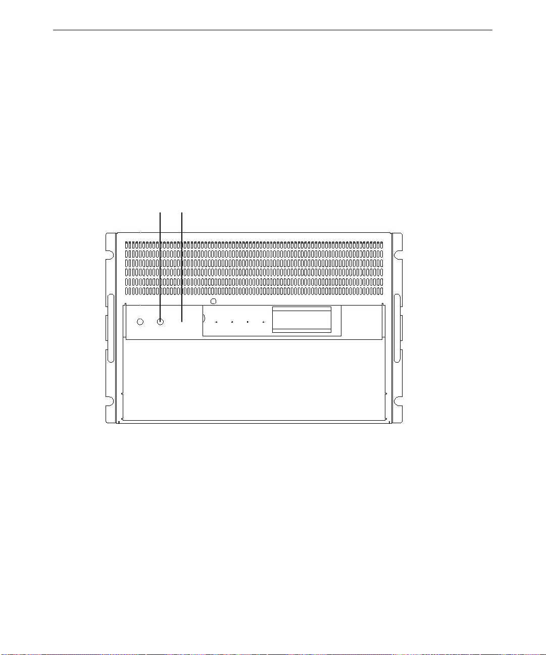
The following figures show the system control buttons.
A B
(View with Lockable Door Open)
Page 37
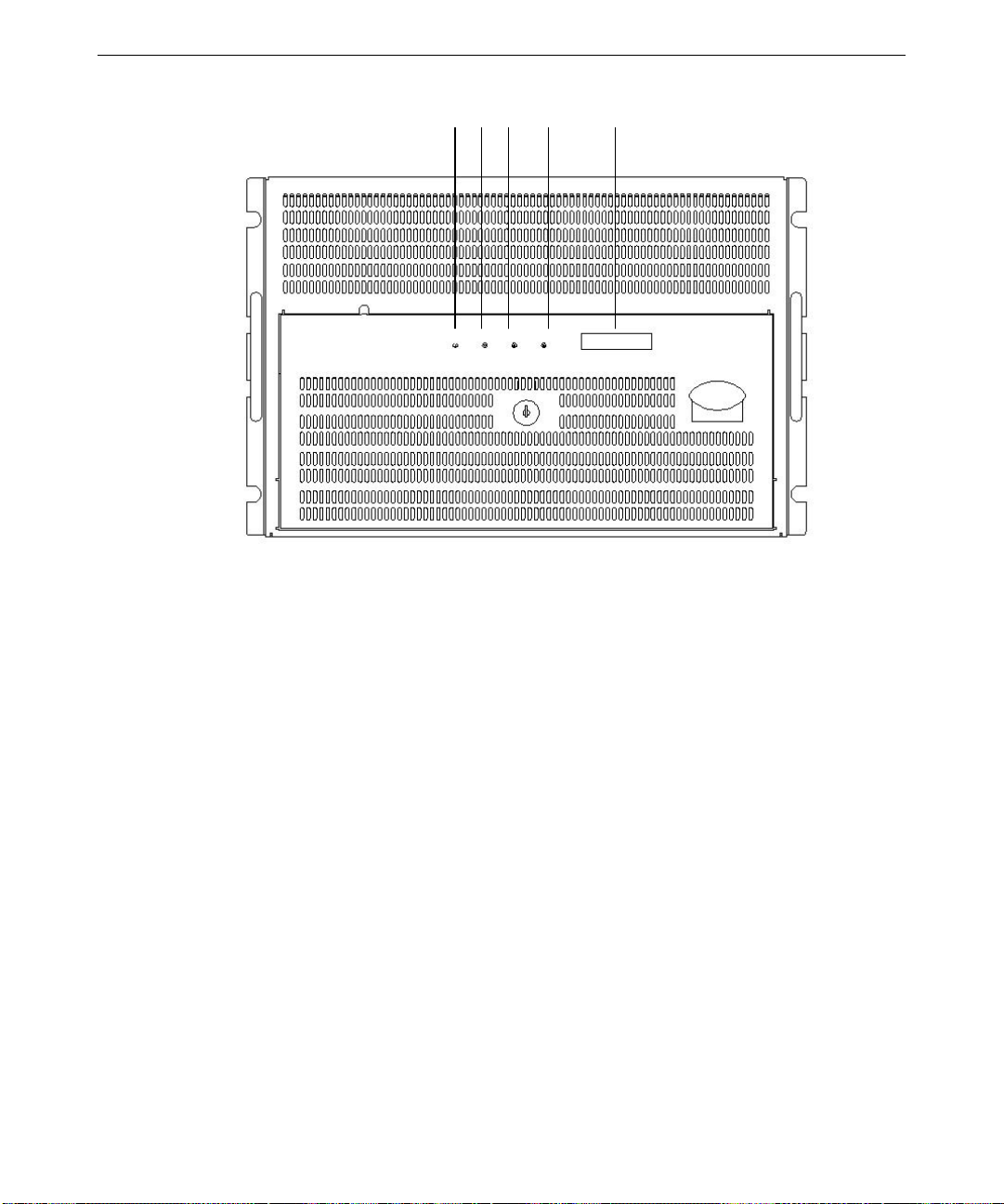
C D E F G
29
Pressing the Reset button clears system memory, restarts power-on self-test (POST), and reloads
the operating system.
To stop the system, perform an orderly shutdown and then press the power button. An orderly
shutdown consists of stopping all running applications and logging off Windows NT by clicking on
Start on the display screen and then selecting Shutdown.
(View with Lockable Door Closed)
View with Lockable Door Open:
A. Power switch (inside lockable door)
B. Reset switch (inside lockable door)
View with Lockable Door Closed:
C. Power LED (green)
D. Power fault LED (yellow)
E. Cooling fault LED (yellow)
F. Drive fault (yellow)
G. Front panel LCD
Page 38

30
If external InterRAID disk cabinets are connected to the system, always power the system on or off
as follows:
♦ Turn on power to the InterRAID cabinets first, listen for the audible beep, and then turn on
power to the system base unit.
♦ Turn off power to the system base unit first (as described previously), and then turn power off
to the InterRAID cabinets. If you turn off power to the InterRAID cabinets first, the RAID
controller will read the drives in those cabinets as dead the next time you power on the system.
If this happens, refer to the Mylex documentation for drive recovery procedures.
System Status LEDs
The Light-Emitting Diodes (LEDs) on the front of the system help you determine system status at a
glance. If any of the LEDs are amber, there is a problem in part of the system hardware. If the fan
status LED is amber and the power supply status LED is green, it is possible that the problem is a
fan inside the power supply, rather than a main cooling fan. The LCD display provides a status of
the system. See the System Reference for additional details.
The figure above shows the location of the system status LEDs.
Disk Drive Status LEDs (RAID Systems)
The following table shows the status indications for disk drives in a RAID system.
LED Color
Steady amber Disk drive rebuild in progress, or critical (degraded) array
Blinking amber Disk drive failed
Off Disk drive not installed or not seated
Meaning
System A lert
To ensure system security, the InterServe includes a system alert that detects and reports hardware
faults such as power supply failures. Also, conditions that may lead to component failure, such as
excessive room temperature, are detected.
You can configure the InterSite Server Watchdog software to notify you if an alert is triggered.
When a hardware fault occurs, the system alert sounds an alarm. Refer to the printed and online
documentation delivered with the InterSite Watchdog software for more information about
notification.
Page 39

Using InterSite Programs
InterServe 9400 systems ship with the following InterSite programs:
♦ InterSite Version Manager is a tool for creating system software backup diskettes, and for
updating device drivers and other system software products installed on the system.
♦ InterSite DMI Console gives easy access to the system’s status and configuration information.
The Console is based on the Desktop Management Interface (DMI), thr ough a window
containing a graphical information tree view pane, a service provider component information
pane, and a message pa ne. DMI Console works with the Desktop Manage ment Inte rface
(DMI), a technology standard that enables the effective management of personal computers
(PCs).
♦ InterSite Watchdog is a system monitoring tool with remote monitoring capabilities. You can
install Watchdog on a system running Windows NT , and use it to monitor workstations and
servers also running Wi ndows NT.
From the operating system Start menu, go to Programs/InterSite to find the InterSite programs on
your system. See the online Help for each InterSite program for more information on how to use
the program.
31
Additional User Information
User information for the following hardware is provided in separate documents, delivered with the
system.
♦ RAID or SCSI controller
♦ Networking card
♦ Uninterruptible Power Supply
♦ Concentrator
♦ Keyboard
♦ Pointing or tracking device
♦ InterSite Server Monitor II card
Additional technical information about the system is included in the System Reference document.
If the system came with an Intergraph rack, refer to the documentation delivered with the rack and
other rack-mounting equipment for information and safety precautions related to using the system
in a rack.
Page 40

32
What’s Next?
See the System Reference for information to configure the BIOS. It describes how to use BIOS
Setup to configure the system BIOS. The System Reference also has troubleshooting information
to resolve common system problems
Page 41

5 Reinstalling System Software
Follow the instructions in this chapter only if you have to reinstall the operating system and
associated system software on the system.
CAUTION Before you reinstall system software, read and understand the entire chapter.
Before You Begin........................................................................................................................... 34
System Software Products.............................................................................................................. 34
Installing Windows NT Server 4.0 on Systems with 3 GB of Memory or Less ............................. 36
Installing Windows NT Server 4.0 on Systems with More Than 3 GB of Memory....................... 37
Getting Operating System Updates................................................................................................. 39
33
Page 42

34
Before You Begin
Have the following items available:
♦ The information you recorded in Chapter 2, “Setting Up the Software.”
♦ Operating system software CD-ROM, associated diskettes, and documentation. Make sure
you have the Setup diskettes delivered with the operating system. If your system has more
than 3 GB of memory, be sure you have the 4
place of the setup diskettes delivered with the operating system.
♦ Backup diskettes you created according to instructions in Chapter 2, “Setting Up the
Software,” or which were delivered with the system.
NOTE Backup media for products such as InterSite is delivered on the System CD.
♦ Backup media and documentation delivered with any option cards or additional pe ripheral
devices purchased from Intergraph.
♦ The Late-Breaking News document delivered with your system, if applicable.
GB_NTSSETUP diskettes, which you will use in
NOTE On a system with Windows NT Terminal Server, refer to the
Server Start Here
You can find the system software on diskettes or CD-ROM provided by Intergraph or on the
operating system CD-ROM. If you did not create backup diskettes of drivers or other system
software products, they are probably available on the operating system CD-ROM or on backup
media delivered with the system.
Driver software is routinely improved and updated. Visit the Intergraph Computer Systems site on
the World Wide Web and vendor bulletin boards for new and updated drivers.
Review the Late-Breaking News document delivered with your system for any additional tasks you
may have to perform during installation.
document for installation instructions.
System Software Products
If a system software product is not listed in the following table, but is installed on your system, the
product is available from an operating system software CD-ROM, or is delivered with an
expansion board or additional p e ripheral device.
NOTE You received an Option Pack CD and you may have received a Service Pack CD.
Service Pack 3 software can be installed from the Option Pack CD. If you have both
CDs and choose to install both, be sure to install the Service Pack 3 software first,
then Option Pack, and then the later Service Pack.
Windows Terminal
Page 43

The following table lists drivers and other system software products typically installed on
InterServe 9400 systems.
35
Product
4GB_NTSSETUP Windows NT Server 4.0 Setup diskettes
Description Delivery Method
Diskette
modified to support systems with more
than 3 GB physical memory
3COM3C90X 3COM 3C905 driver Version Manager and diskette
or CD
MYLEXPCIDRV Mylex RAID driver and utilities Version Manager and diskette
or CD; with RAID systems
only
CIRRUSNTDRV Cirrus 5480 graphics display driver Version Manager and diskette
or CD
LMOUSE Logitech mouse driver Version Manager and diskette
or CD
QFE* Quick-Fix Engineering Upda te post-
Service Pack hotfixes. Review the
Version Manager a nd diskette
or CD
README.TXT in any QFE product
delivered with your system to see if it
applies to your configuration.
PCI_HOT_PLUG Hot Plug PCI Utility Version Manager and CD
SYMLVDSCSI Symbios LVD SCSI driver Version Manager and diskette
or CD
FLASH_9400 Flash Program Utility Version Manager and CD
DMI InterSite Desktop Manager Interface Version Manager and CD
IM InterSite Manager Version Manager and CD
VERMANAGER InterSite Version Manager Version Manager and CD
WATCHDOG InterSite Watchdog Version Manager and CD
WELCOME Welcome Utility Version Manager and CD
Page 44

36
Installing Windows NT Server 4.0 on Systems with 3 GB of Memory or Less
Use this section to install Windows NT Server 4.0 if your system has 3 GB of memory or less. If
your system has more than 3 GB of memory, see “Installing Windows NT Server on Systems with
More Than 3 GB of Memory.”
CAUTION If your system is equipped with an internal RAID section or an external RAID disk
array, and your system drive is part of the RAID set, you must select the RAID level
and configure the RAID before you start Windows NT Setup and install Windows NT
Server. Refer to the Mylex documentation for instructions on configuring the RAID
disk array. Then return to this document and install Windows NT Server.
To install Windows NT Server on systems with 3 GB of memory or less:
Follow the instructions in Start Here to install Windows NT, and do the following steps as you
install the operating system:
♦ Select Custom Setup.
♦ Press
♦ When prompted to detect mass storage devices, press S to skip automatic detection, then press
♦ You can safely select the default responses for other options in Setup except when installing
♦ Create an Emergency Repair Disk when prompted.
After installing the operating system:
♦ Restart the system.
♦ Install the InterSite software products from the System CD. Insert the System CD and follow
♦ Configure the system as described in Chapter 3, “Configuring the System.”
♦ Perform any additional installation and configuration tasks described in any Late-Breaking
F8 to accept the End User License Agreement (EULA).
S to install SYMSCSI if you have a Symbios host bus adapter in your system (JBOD systems),
or the MYLEXPCIDRV driver if you have a Mylex RAID card, from the backup diskette.
networking. When prompted to select a network adapter, c lick Have Disk. Insert
3COM3C90X disk 1 and click OK. From the list, select 3Com Fast Etherlink XL Adapter
(3C905) and press
the instructions displayed in the System CD window.
News document delivered with your system.
ENTER. Follow the instructions on screen to complete network installation.
Page 45

Installing Windows NT Server 4.0 on Systems with More Than 3 GB of Memory
The following actions are not required to install Windows NT Server, Enterprise Edition 4.0 or
Windows NT Server, Terminal Server Edition 4.0. These actions are only required if you install
Windows NT Server 4.0.
CAUTION If your system is equipped with more than 3 GB of memory, you cannot install
Windows NT Server 4.0 unless you do one of the following:
♦ Remove one memory DIMM from the base unit. You must remove the DIMM residing in the
last bank (highest). Follow the instructions in the System Reference to access the DIMM
memory modules. Remove only the DIMM from slot J16. Close the base unit, turn on system
power, install Windows NT Server following the instructions in “Installing Window NT
Server 4.0 on Systems with 3 GB of Memory or Less,” and then install Service Pack 3 or later.
After the system boots properly, turn off system power and reinstall the DIMM in slot J16.
37
♦ If you do not remove the memory DIMM, use the 4
GB_NTSSETUP diskettes provided with your
system instead of the setup diskettes provided by Microsoft with your NT Server kit. Perform
the following instructions.
CAUTION If your system is equipped with an external RAID disk array, and your system drive is
part of the RAID set, you must select the RAID level and configure the RAID before
you start Windows NT Setup and install Windows NT Server. Refer to the RAID
documentation for instructions on configuring the RAID disk array. Then return to
this document and install Windows NT Server.
NOTE The partition to which you are installing must be either unformatted or formatted
using the FAT file system. The partition cannot be NTFS when you start to install the
operating system. If it is already formatted NTFS, you will not be able to edit the
boot.ini file, which is necessary to complete the installation. If desired, you can
remove an existing NTFS partition during NT setup and select to have it reformatted
to NTFS as part of the installation process.
To install Windows NT Server on systems with more than 3 GB of memory:
1. Insert 4
2. When prompted, insert 4
3. When prompted to detect mass storage devices, press
4. Press
5. Select Other and press
GB_NTSSETUP Disk 1 in the system’s floppy disk drive and turn on system power.
GB_NTSSETUP Disk 2 and press ENTER.
S to skip.
S again to specify devices.
ENTER.
6. Insert the Mylex diskette and press
7. When prompted, press
S to specify additional devices.
ENTER.
Page 46

38
8. Select Other and press ENTER.
9. Insert the
10. When prompted, press
MYLEXPCIDRV Disk 1 diskette and press ENTER.
S to specify additional devices.
11. Use the arrow key to scroll up, then select IDE CD-ROM (ATAPI 1.2)/PCI IDE
CONTROLLER and press
12. When prompted, insert 4
ENTER.
GB_NTSSETUP Disk 3 and press ENTER.
13. Accept the mass storage device configuration when displayed on the screen, and insert the NT
Server CD-ROM in the CD-ROM drive when prompted.
14. Follow the instructions on the screen to select or create a partition.
NOTE You must select an unformatted or FAT formatted partition. You cannot use an
existing NTFS partition. If you create a new partition, the maximum size is restricted
to 4096 KB. After you select a partition, you can select to have it formatted using
NTFS file system.
15. At the “Remove all diskettes and restart the system” prompt, insert 4GB_NTSSETUP Disk 4 and
press
ENTER to restart the system.
16. At the DOS prompt, key in attrib -s -h -r c:\boot.ini.
17. At the DOS prompt, key in edit c:\boot.ini.
18. The
BOOT.INI file opens in edit mode. It will contain a section similar to the following:
[operating systems]
multi(0)disk(0)rdisk(0)partition(1)\WINNT="Windows NT Server Version 4.00"
multi(0)disk(0)rdisk(0)partition(1)\WINNT="Windows NT Server Version 4.00 [VGA mode]"
/basevideo /sos
19. Type /maxmem=256 as shown in the following:
[operating systems]
multi(0)disk(0)rdisk(0)partition(1)\WINNT="Windows NT Server Version 4.00" /maxm em=256
multi(0)disk(0)rdisk(0)partition(1)\WINNT="Windows NT Server Version 4.00 [VGA mode]"
/basevideo /sos
20. Save the file and exit.
21. At the DOS prompt, type attrib +s +h c:\boot.ini.
22. Remove the diskette and press
ALT+CTRL+DEL to restart the system.
23. Select the default responses for the remaining options in Setup except when installing
networking. When prompted to select a network adapter, c lick Have Disk. Insert 3
COM3C90X
disk 1 and click OK. From the list, select 3Com Fast Etherlink XL Adapter (3C905) and press
ENTER. Follow the instructions on screen to complete network installation.
Page 47

After installing the operating system:
♦ Restart the system.
39
♦ Edit
C:\BOOT.INI (see following procedure).
♦ Install the InterSite software products from the System CD. Insert the System CD and follow
the instructions displayed in the System CD window.
♦ Configure the system as described in Chapter 3, “Configuring the System.”
♦ Perform any additional installation and configuration tasks described in the Late-Breaking
News document delivered with your system.
To edit
C:\BOOT.INI:
1. In Windows Explorer, select Options from the View menu.
2. Click Show all files and uncheck Hide file extentions for known file types; then click OK.
3. In Windows Explorer, go to C: and double-click
BOOT.INI with the left mouse button to open
the file in Notepad. It will contain a section similar to the following:
[operating systems]
multi(0)disk(0)rdisk(0)partition(1)\WINNT="Windows NT Server Version
4.00" /maxmem=256
multi(0)disk(0)rdisk(0)partition(1)\WINNT="Windows NT Server Version
4.00 [VGA mode]" /basevideo /sos
4. Delete the text shown in bold in the example above so the section looks like the following:
[operating systems]
multi(0)disk(0)rdisk(0)partition(1)\WINNT="Windows NT Server Version
4.00"
multi(0)disk(0)rdisk(0)partition(1)\WINNT="Windows NT Server Version
4.00 [VGA mode]" /basevideo /sos
5. Save and exit from the file.
6. Highlight
C:\BOOT.INI, click the right mouse button and select Properties. Check the Read-
only box and click OK.
Getting Operating System Updates
Microsoft Service Packs and Service Releases contain the latest improvements and system fixes for
Microsoft operating systems. Service Packs and Service Releases are created by Microsoft for
post-release support. You can get them from Microsoft’s World Wide Web and FTP sites free of
charge. Post-service pack hotfixes are also available on the Microsoft web site.
CAUTION If Intergraph provides a Service Pack or Service Release through its online services or with a
product or system, it has been certified against Intergraph hardware as described in the
Page 48

40
announcement of its availability. If you obtain a Service Pack or Service Release from any other
source, be aware that it may not be certified against your Intergraph hardware.
Page 49

Returned Goods Authorization (RGA) Form
Date Returned Serial No.
(On white bar code ID plate under top cover)
RGA No.
From Customer Name
Customer Contact Phone
Mail Address
Reason for Return
(From Intergraph Customer Response Center)
NOTE All returned equipment MUST be shipped in original Intergraph packaging to obtain warranty
service.
WARNING Back up disk drives before returning equipment. Intergraph is not responsible for data
lost in shipping or repair process.
Page 50

Warranty Procedure
Some malfunctioning equipment cannot be repaired in the field, and you must return it to Intergraph for
repair. Follow these steps to obtain a Returned Goods Authorization (RGA) log number and return the
malfunctioning equipment.
1. Determine the serial number of the system. The serial number is located on the white bar code
identification label on the back of the base unit.
2. Call the Intergraph Customer Response Center at 1-800-633-7248, and identify your call to the
operator as a Warranty Call. After giving the operator the serial number of the system, you will be
assigned a RGA log number.
3. Complete the RGA Form on the previous page, entering the RGA log number obtained from the
Customer Response Center. Ensure that the address in the From section is the location to which you
want the equipment to be returned.
4. Place the RGA form in the box containing the equipment. This form must accompany returned
equipment.
5. Secure a Repair Depot address label from the next page to the box containing the equipment.
6. Ship the box containing the equipment to Intergraph.
When the service activity has been completed by Intergraph, the repaired or replaced equipment will be
shipped to the address listed on the RGA Form.
NOTE Parts damaged during shipping and parts not covered by the warranty are liable for repair
charges.
Page 51

TO Repair Depot RGA No. _______________________
Intergraph Corporation
9805 Kellner Road
Huntsville AL 35894
TO Repair Depot RGA No. _______________________
Intergraph Corporation
9805 Kellner Road
Huntsville AL 35894
TO Repair Depot RGA No. _______________________
Intergraph Corporation
9805 Kellner Road
Huntsville AL 35894
Page 52

 Loading...