

Page 1

InterServe 9000
System Setup
October 1998
DHA031200
Page 2

Copyright
1998 Intergraph Computer Systems. All rights reserved. This document contains information protected by copyright, trade secret, and
trademark law. This document may not, in whole or in part, be reproduced in any form or by any means, or be used to make any derivative work,
without written consent from Intergraph Computer Systems.
Use, duplication, or disclosure by the United States Government is subject to restrictions as set forth in subdivision (c)(1)(ii) of the rights in
technical data and computer software clause at DFARS 252.227-7013. Unpublished rights are reserved under the copyright laws of the United
States.
Intergraph Computer Systems, Huntsville AL 35894-0001
Notice
Information in this document is subject to change without notice and should not be considered a commitment by Intergraph Computer Systems.
Intergraph Computer Systems shall not be liable for technical or editorial errors in, or omissions from, this document. Intergraph Computer
Systems shall not be liable for incidental or consequential damages resulting from the furnishing or use of this document.
All warranties given by Intergraph Computer Systems about equipment or software are set forth in your purchase contract. Nothing stated in, or
implied by, this document or its contents shall be considered or deemed a modification or amendment of such warranties.
Trademarks
Intergraph Computer Systems and the Intergraph Computer Systems logo are registered trademarks of Intergraph Computer Systems. InterServe
is a trademark of Intergraph Computer Systems.
Other brands and product names are trademarks of their respective owners.
FCC/DOC Compliance
This equipment has been tested and found to comply with the limits for a Class B digital device, pursuant to part 15 of the FCC Rules. These
limits are designed to provide reasonable protection against harmful interference when the equipment is operated in a residential installation.
This equipment generates, uses, and can radiate radio frequency energy. If the equipment is not installed and used in accordance with the
instructions, it may cause harmful interference to radio communications. However, there is no guarantee that interference will not occur in a
particular installation.
If this equipment does cause harmful interference to radio or television reception, which can be determined by turning the equipment off and on,
try to correct the interference as follows: reorient or relocate the affected device; increase the separation between this equipment and the
affected device; connect this equipment to an outlet on a circuit different from the circuit to which the affected device is connected; consult a
dealer or an experienced radio/television technician for help.
This Class B digital apparatus meets all requirements of the Canadian Interference-Causing Equipment Regulations. Cet appareil numérique de
la classe B respecte toutes les exigencies du Règlement sur le materiél brouilleur du Canada.
Warnings
To comply with FCC Class B limits, you must use shielded cables with this device.
Changes or modifications made to the system that are not approved by the party responsible for compliance could void the user's authority to
operate the equipment.
To reduce the risk of electrical shock, do not attempt to open the equipment unless instructed. Do not use a tool for purposes other than
instructed.
There is a danger of explosion if the battery is incorrectly replaced. Replace the battery only with the same or equivalent type as recommended
by the manufacturer. Dispose of used batteries according to the manufacturer's instructions.
Notes
Read all operating instructions before using this device. Keep these instructions for future reference. Follow all warnings on the device or in the
operating instructions.
This device is designed and manufactured to comply with approved safety standards for information processing and business equipment.
Page 3

Contents
Preface................................................................................................................................v
About This Document.......................................................................................................... v
Document Conventions........................................................................................................ v
Operating System Information ............................................................................................. v
Hardware Information......................................................................................................... vi
Ergonomic Information...................................................................................................... vii
Customer Support.............................................................................................................. vii
1 Setting Up the Hardware............................................................................................... 1
Before You Begin................................................................................................................ 2
Unpacking the Equipment.................................................................................................... 3
Placing the System............................................................................................................... 4
Setting Up a Deskside System.............................................................................................. 5
Setting Up a Rack-mount System......................................................................................... 6
Prepare the Equipment Rack................................................................................................ 7
Prepare the System............................................................................................................. 11
Installing the System into a Rack ....................................................................................... 14
Connecting the Cables ....................................................................................................... 15
Installing Non-RAID and RAID Disk Drives ..................................................................... 17
Checking the System.......................................................................................................... 21
What’s Next?..................................................................................................................... 22
iii
Hardware and Software Support Services............................................................. vii
World Wide Web................................................................................................. vii
Intergraph Bulletin Board Service ........................................................................ vii
FAXLink.............................................................................................................viii
Telephone ........................................................................................................... viii
More Support Options........................................................................................... ix
Safety Guidelines................................................................................................... 6
Tools You Need..................................................................................................... 7
Install and Label the Disk Drives ......................................................................... 18
Additional Information......................................................................................... 21
2 Setting Up the Software............................................................................................... 23
Preparing for Setup............................................................................................................ 24
Pre-Installed Software.......................................................................................... 24
Before You Start Setup......................................................................................... 24
Starting the System............................................................................................................ 26
Starting Operating System Setup........................................................................................ 26
Finishing Operating System Setup ..................................................................................... 27
Creating an Emergency Repair Disk..................................................................... 27
Creating System Software Backup Diskettes......................................................... 28
What’s Next?..................................................................................................................... 28
Page 4

iv
3 Configuring the System................................................................................................ 29
Configuring the Video Display........................................................................................... 30
Changing the Default Video Display Driver ......................................................... 30
Correcting Video Display Problems...................................................................... 30
Installing Mylex RAID Software........................................................................................ 31
Configuring Drives for a RAID Disk Array........................................................................ 32
Standard RAID Disk Drives Configuration........................................................... 32
Additional RAID Disk Drives Configuration........................................................ 35
Installing and Configuring LanSafe UPS Software............................................................. 36
Installing QFE Update Software......................................................................................... 37
Installing Intel Server Control (ISC) Software.................................................................... 37
Creating an Emergency Repair Disk .................................................................................. 37
Getting Operating System Updates..................................................................................... 37
4 Operating Notes ........................................................................................................... 39
Starting and Stopping the System ...................................................................................... 40
System Status LEDs........................................................................................................... 41
Disk Drive Status LEDs (RAID Systems)........................................................................... 42
System Alert...................................................................................................................... 42
Using InterSite Programs................................................................................................... 43
Additional User Information .............................................................................................. 43
What’s Next?..................................................................................................................... 44
5 Reinstalling System Software ...................................................................................... 45
Before You Begin.............................................................................................................. 46
System Software Products.................................................................................................. 46
Installing Windows NT Server 4.0 on Systems with 3 GB of Memory or Less.................... 48
Installing Windows NT Server 4.0 on Systems with More Than 3 GB of Memory.............. 49
Getting Operating System Updates..................................................................................... 52
Index................................................................................................................................. 53
Returned Goods Authorization (RGA) Form
Warranty Procedure
Repair Depot Address Labels
Page 5

Preface
InterServe 9000 System Setup describes setting up, configuring, and operating your
InterServe 9000 system.
About This Document
InterServe 9000 System Setup is organized as follows:
u
Chapter 1, “Setting Up the Hardware,” describes how to set up the system hardware.
u
Chapter 2, “Setting Up the Software,” describes how to set up the operating system and
associated system software.
u
Chapter 3, “Configuring the System,” describes how to configure the system for use.
u
Chapter 4, “Operating Notes,” describes how to use essential system features and
provides other important information.
u
Chapter 5, “Reinstalling System Software,” describes how to reinstall the operating
system and associated system software, if required.
v
Document Conventions
Bold
Italic Variable values that you supply, or cross-references.
Monospace
SMALL CAPS Key names on the keyboard, such as D, ALT or F3; names of files and
CTRL+D Press a key while simultaneously pressing another key; for example, press
Commands, words, or characters that you key in literally.
Output displayed on the screen.
directories. You can type filenames and directory names in the dialog boxes
or the command line in lowercase unless directed otherwise.
CTRL and D simultaneously.
Operating System Information
For more detailed information on the operating system, see the printed and online Microsoft
documentation delivered with the system.
See the Late-Breaking News shipped with your system for important software and
documentation information not covered in this document.
Page 6

vi
Hardware Information
An online introduction to your new system is provided in the System Introduction, which
covers subjects such as the following:
u
System features
u
System controls and connections
u
Intergraph customer support
You can display the System Introduction by using the InterSite Welcome dialog or by
opening the
Detailed reference information for your new system is provided in the System Reference,
which covers user and service technician subjects such as the following:
Part I, User’s Guide:
•
System, peripherals, and power supplies.
•
System board (slots and sockets, memory configurations, IRQ/DMA/upper memory
assignments, jumpers, external ports, hardware monitoring).
SYSINTRO.HLP file on your system.
•
Hot keys, power-on self-test (POST), BIOS Setup, and other utilities.
•
Hot-swap hard disk drives and power supplies.
Part II, Service Technician’s Guide:
•
Base unit components.
•
System board (memory, processors, and backup battery).
•
Troubleshooting checklist.
•
Hardware technical reference and system interrupt requests (IRQs).
•
Log sheet and configuration worksheets.
•
Specifications (electrical, environmental, physical).
•
Precautions against electrostatic discharges.
See the Late-Breaking News shipped with your system for important hardware and
documentation details not covered in this document.
Page 7

Ergonomic Information
Read the Ergonomics Guide delivered with your system for valuable information on ways to
minimize repetitive stress injuries when working with a computer.
Customer Support
Intergraph Computer Systems offers an assortment of customer support options.
Hardware and Software Support Services
Intergraph Computer Systems provides a variety of hardware services for Intergraph and
third-party equipment. Services include warranty upgrades, repair depot service, on-site
hardware maintenance, system administration, and network consulting. Hardware
purchased from Intergraph Computer Systems includes a factory warranty ranging from
30 days to three years. A detailed warranty description is available on the World Wide Web;
see the Support pages at http://www.intergraph.com/ics.
Intergraph Computer Systems provides complimentary software support for 30 or 90 days
following shipment of a hardware or software product. This includes World Wide Web
access, Intergraph Bulletin Board Service access, FAXLink service, and telephone (Help
Desk) support. At the end of the complimentary support period, you can purchase other
levels of software support.
vii
World Wide Web
You can visit Intergraph Computer Systems on the World Wide Web at
http://www.intergraph.com/ics. On these pages, you can get news and product
information, technical support information, software updates and fixes, and more.
Intergraph Bulletin Board Service
On the Intergraph Bulletin Board Service (IBBS), you can get technical support information,
software updates and fixes, and more.
To connect to the IBBS:
1. Set your system’s communications protocol for eight (8) data bits, no parity, one (1) stop
bit, and any baud rate up to 14,400.
Page 8

viii
FAXLink
2. Using a modem, call 1-256-730-8786. Outside the United States, call one of the mirror
sites listed on World Wide Web; see the Software Support pages at
http://www.intergraph.com.
3. At the login prompt, key in your user ID. If you have not connected before, key in new
to create a user ID.
4. Follow the menus to find what you need. The IBBS provides clear choices and online
help.
If you have trouble connecting to or using the IBBS, call the Customer Response Center at
1-800-633-7248 (product entry IBBS) or leave a message for the IBBS System Operator at
1-256-730-1413.
To use the FAXLink:
u
Call 1-800-240-4300 for information on how to get technical support information using
the FAXLink.
u
Call 1-256-730-9000 to get documents (up to five per call).
Telephone
To get customer support by telephone:
u
u
Have the following information available when you call:
u
u
u
u
In the United States, call 1-800-633-7248 between the hours of 7:00 a.m. and
7:00 p.m. Central Time, Monday through Friday (except holidays).
Outside the United States, contact your local Intergraph Computer Systems subsidiary or
distributor.
Your service number, which identifies your site to Intergraph Computer Systems. You
use your service number for warranty or maintenance calls.
Your Customer Personal Identification Number (CPIN). You get a CPIN the first time
you call the Customer Response Center; it is associated with your service number for
future call logging.
The product’s name or model number.
The product’s serial number. Software product serial numbers are included in the
product packaging. Hardware product serial numbers are on a sticker affixed to the
hardware product.
Page 9

u
Your name and telephone number.
u
A brief description of the question or problem.
More Support Options
To get information on more customer support options:
u
Visit the Support pages on the World Wide Web at http://www.intergraph.com/ics.
u
For hardware support questions in the United States, call 1-800-763-0242.
u
For software support questions in the United States, call 1-800-345-4856.
u
Outside the United States, contact your local Intergraph Computer Systems subsidiary or
distributor.
ix
Page 10

x
Page 11

1 Setting Up the Hardware
Follow the instructions in this chapter to set up an InterServe 9000 in a stand-alone deskside
configuration or to set up and install it into an Intergraph equipment rack.
Before You Begin................................................................................................................ 2
Unpacking the Equipment.................................................................................................... 3
Placing the System............................................................................................................... 4
Setting Up a Deskside System.............................................................................................. 5
Setting Up a Rack-mount System......................................................................................... 6
Safety Guidelines................................................................................................... 6
Tools You Need..................................................................................................... 7
Prepare the Equipment Rack................................................................................................ 7
Prepare the System............................................................................................................. 11
Installing the System into a Rack ....................................................................................... 14
Connecting the Cables ....................................................................................................... 15
Installing Non-RAID and RAID Disk Drives ..................................................................... 17
Install and Label the Disk Drives ......................................................................... 18
Additional Information......................................................................................... 21
Checking the System.......................................................................................................... 21
What’s Next?..................................................................................................................... 22
1
Page 12

2
Before You Begin
Read this chapter before you attempt to set up an InterServe 9000. In addition:
u
Contact the local Intergraph support office if any items you ordered are missing or
damaged.
u
If you use non-Intergraph cables with the system, ensure that they are shielded and
terminated on both ends. Intergraph-supplied cables are shielded to prevent excessive
electromagnetic interference (EMI).
u
If using an external power source with your system, such as an AC distribution box or
an uninterruptible power supply (UPS), review the documentation delivered with the
power source for information about its capabilities.
u
If you need to return equipment for repair, you must ship it in Intergraph-supplied
packaging to get warranty service.
u
Follow the installation instructions carefully to avoid personal injury and damage to the
system hardware.
If you are installing the system into a rack, note the following.
u
Set up the Intergraph rack using the Intergraph Rack Installation and Use document
delivered with the rack. Become familiar with the rack enclosure before installing the
system hardware into it.
u
Do not push on or lean against the rack.
u
The rack’s front and side stabilizer feet must be extended at all times.
Page 13

Unpacking the Equipment
InterServe 9000
Corrugated
Sleeve
The InterServe 9000 base unit is between two foam pieces, and rack-mount versions include
a corrugated sleeve as part of the packing. Other items are packed in boxes.. Contents of the
boxes are as follows:
3
Parts Box
Disk
Drives
Box
u
Parts box -- contains the keyboard, mouse, and key (for the drive access door); Windows
NT Server operating system (compact disks, floppy diskettes, and documentation), if
ordered; Intergraph system software (diskettes); label sheets for disk drives; and
documentation.
u
Disk drives box -- each box contains up to three disk drives. If you ordered more than
three drives, they are delivered in an extra box.
If you ordered a monitor from Intergraph Computer Systems, it is shipped separately from
the base unit pallet. Its carton contains the monitor, the monitor AC power cord, the video
cable, and monitor documentation.
NOTE If any of the listed items were not delivered, call the Customer Response Center immediately
at 1-800-633-7248.
Save all packaging materials after setting up the system. If you return equipment for repair,
it must be in its original packaging for you to get warranty service (if provided under your
contract agreement).
Page 14

4
Placing the System
Operation of the InterServe 9000 system at conditions beyond those shown in the following
table may cause permanent damage to the system. Exposure to conditions outside the
absolute maximum ratings for extended periods may affect system reliability.
The following table provides the absolute maximum conditions.
Condition
Range
Operating temperature 0° C to +40° C
Storage temperature -55° C to +150° C
Voltage on any signal with respect to ground
-0.3V to *V
+ 0.3 V
DD
3.3V supply voltage with respect to ground -0.3 to +3.63 V
5V supply voltage with respect to ground -0.3 to +5.5 V
12V supply voltage with respect to ground -0.3 to +12.6 V
-12V supply voltage with respect to ground -13.2 to +0.3 V
means supply voltage for the device.
* V
DD
The InterServe 9000 either stands upright (pedestal mode) or installs in a rack (rack mode).
Before you set up your system, determine where you want to place it. Keep these guidelines
in mind:
u
Place the system as close as possible to the proper power outlet. The power cord
connecting the system to the facility power outlet or other power source serves as the
disconnect device.
u
Place the system in an area where air can circulate freely around it.
u
Do not expose the system to high levels of dust, smoke, or moisture.
u
Place the system in an area where the temperature range stays between 10° C and 26° C
(50° F and 80° F). The optimum operating temperature is 21° C (70° F).
u
Place the system in an area where the humidity stays between 20 percent and 80 percent
(non-condensing). The optimum operating humidity is 50 percent (non-condensing).
Install the system as described in “Setting up a Deskside System” or “Setting up a Rackmount System,” as appropriate.
Page 15

Setting Up a Deskside System
This section explains how to install a deskside (pedestal) system.
5
To set up the system:
1. Lift the base unit from the pallet and set it upright.
WARNING The base unit is heavy; two people are required to lift it out of the box. Do not let the
base unit drop onto a hard surface, or damage to internal components may result.
2. Remove the plastic bag from the base unit.
3. Connect the cables as described later in this chapter under “Connecting the Cables.”
Page 16

6
Setting Up a Rack-mount System
This section explains how to install a rack-mount InterServe 9000 system in a 19-inch
Intergraph 17 U or 40 U equipment rack. Only technically qualified personnel should install
the system. Computer equipment is secured in the rack along the mounting posts using 7.1
mm diameter mounting holes. The mounting posts have small round markers to designate
each U. There are three mounting holes per U. Further details are found in this section.
The size of racks are designated by their available vertical height and width. Knowing the
size of the rack and equipment you are installing helps determine if the rack is capable of
containing the equipment.
NOTE Physical space is not the only factor to consider when installing equipment. There are facility
and power requirements and load limitations to observe. For more information about power
requirements and load limitations, see the documentation delivered with the system and
equipment.
Safety Guidelines
Before you set up a system, please read and observe the following safety guidelines:
WARNING Avoid injury: The minimum system configuration weighs 29 kg (63 lbs), and the
maximum weighs 44 kg (97 lbs). To avoid injury, two people should lift and insert the
system into the slide assemblies in the equipment rack.
WARNING Work on only one system at a time: Extend only one system at a time from the
equipment rack. Extending more than one system can result in the rack tipping
forward on you.
WARNING Anchor the equipment rack:
support to prevent it from falling over when a system on slide assemblies is extended
in front of it. The anchors must be able to withstand a force of up to 113 kg (250 lbs).
You must also consider the weight of any other device installed in the rack.
WARNING Main AC power disconnect:
disconnect for the entire rack unit. This main disconnect must be readily accessible,
and it must be labeled as controlling power to the entire unit, not just to the system(s).
WARNING Grounding the rack installation: To avoid the potential for an electrical shock hazard,
you must include a third wire safety grounding conductor with the rack installation. If
system power cords are plugged into AC outlets that are part of the rack, then you
must provide proper grounding for the rack itself. If system power cords are plugged
into wall AC outlets, the safety grounding conductor in each power cord provides
proper grounding only for the system. You must provide additional, proper grounding
for the rack and other devices installed in it.
The equipment rack must be anchored to an unmovable
You are responsible for installing an AC power
Page 17

WARNING Overcurrent protection: The system is designed for an AC line voltage source with up
to 20 amperes of overcurrent protection. If the power system for the equipment rack
is installed on a branch circuit with more than 20 amperes of protection, you must
provide supplemental protection for the system. If more than one system is installed
in the rack, the power source for each system must be from a separate branch circuit.
The overall current rating of a system configured with three power supplies is under
12 amperes.
7
CAUTION Temperature:
must not go below 5° C (41° F) or rise above 35° C (95° F). Extreme fluctuations in
temperature can cause a variety of problems in your system.
CAUTION Ventilation:
maintain proper cooling. It must also include ventilation sufficient to exhaust a minimum of
3,150 Btu's per hour for the system. The rack selected and the ventilation provided must be
suitable to the environment in which the system will be used.
The operating temperature of the system, when installed in an equipment rack,
The equipment rack must provide sufficient airflow to the front of the system to
Tools You Need
You will need the following tools:
u
Phillips screwdrivers, #1 and #2
u
Pencil
Prepare the Equipment Rack
Before installing the system in the 19-inch equipment rack, you must attach the slide rails
and mounting brackets to the equipment rack as instructed in this section. Perform the
following steps carefully; the mounting brackets must be installed with precision to allow
room for the next system you install in a rack.
NOTE A total of four mounting brackets (two long and two short) attach to the vertical rails of the
equipment rack. The two long brackets must be installed on the front of the equipment rack.
To mark the hole spacing on the vertical rails:
1. See the following figure for a view of the vertical rail and the hole spacing details. The
vertical rails of the 17 U and 40 U racks have a hole between every 1 U, and a square
between every 4 U. All dimensions are in millimeters
2. With a pencil, mark the top and bottom hole locations for the mounting brackets on both
sides of the vertical rails.
Page 18

8
1 U Marker
To attach the mounting brackets to the front vertical rail:
1. Remove a long mounting bracket, two screws, and a bar nut from the kit. See the
following figure for a view of how to place the bar nut in relation to the mounting
bracket and vertical rail.
Bar Nut
Long Mounting
Bracket
Front Vertical Rai l
Phillips flathead screw,
#10-32 x .5
2. While facing the front of the rack, orient the mounting bracket so that the short side
with the four mounting holes is facing toward the outside edge of the vertical rail and
the bracket extends to the back of the rack.
3. Place the bracket on the mounting holes in the vertical rail.
4. Insert a screw through the marked top hole in the vertical rail and through the top hole
in the mounting bracket. Place a bar nut on the screw, and loosely tighten it. Repeat for
the marked bottom hole.
5. Install the other front mounting bracket in the same manner.
Page 19

To attach the mounting brackets to the back vertical rail:
Use the same procedure to install both mounting brackets on the back vertical rails. See
the following figure for proper orientation of the short mounting bracket.
Short Mounting
Bracket
Back Vertic a l Rail
Bar Nut
Phillips flathead screw,
#10-32 x .5
To prepare the slide assemblies:
9
1. Remove the slide assemblies from the kit. See the following figure.
4
1 Large outer bar
2 Center bar
3 Small outer bar
4 Safety latch on the small outer bar
5 Safety latch on the center bar
1 2 3
5
Page 20

10
1
2. Orient a slide assembly so that the smallest outer bar is facing down.
3. Fully extend the telescoping slide assembly until the center bar hits the safety latch on
the small outer bar (all three overlapping bars will be visible).
4. Grasp the small outer bar with your right hand so that your thumb is on the safety latch
of the small outer bar.
5. Press and hold the safety latch down, and at the same time, grasp the large outer bar
with your left hand.
6. Pull the small bar out of the center bar; this takes a little force to separate them. Set the
small bar aside to attach to the chassis in a later step.
7. Orient the center bar and large outer bar assembly so that the center bar is facing up.
8. Grasp the center bar with your right hand and the large outer bar with your left hand so
that your left-hand thumb is on the safety latch of the center bar.
9. Press the safety latch, and slide the bars together. Set the center bar and large outer bar
assembly aside to attach to the equipment rack in a later step.
10. Prepare the other slide assembly by repeating steps 2–9.
To attach the center bar and large outer bar assemblies to the mounting brackets:
1. See the following figure for the center bar and large outer bar assembly.
22
5
4
4
3
2
2
2
6
7
1 Front mounting bracket
2 Screw, #8-32 x.5 Phillips trusshead
3 Kep nut
4 Large outer bar
5 Safety latch on the center bar
6 Center bar
7 Back mounting bracket
6
Page 21

2. Orient a center bar and large outer bar assembly so that the flat side is facing toward the
mounting brackets attached to the vertical rails, and the safety latch on the center bar is
near the back of the rack. Press the flat side of the outer bar into the mounting bracket.
3. Slide the assembly toward the front of the rack until the end of the outer bar is
approximately 90 millimeters from the leading edge of the bracket.
4. Gently slide the center bar toward the front of the rack, and position the oblong slot in it
over the first hole in the large outer bar. Insert an 8-32 screw through the hole in the
bar and the first slot in the front bracket. Place an 8-32 kep nut on the screw, and
loosely tighten it.
5. Position the oblong slot in the center bar over the third hole back from the front of the
large outer bar. Insert an 8-32 screw through the hole and the oblong slot in the front
bracket. Place an 8-32 kep nut on the screw and loosely tighten it.
6. The back mounting bracket has one slot in it. The end of the outer bar has four holes in
it. The holes you use depend on the depth of the equipment rack. After fitting the bar
into the mounting bracket, insert two screws through the appropriate holes in the bar
and the slot in the mounting bracket. Place an 8-32 kep nut on each screw, and loosely
tighten them.
7. Ensure that the mounting brackets and bars are positioned correctly in the rack. Then
tighten all screws firmly (6.0 inch-pounds).
11
Prepare the System
Before installing the base unit in the 19-inch equipment rack, you must attach the small bars
of the slide assemblies onto the sides of the system. You must also attach two chassis
handles to the system faceplate.
To attach the small bar of the slide assembly to the system:
1. Remove four #8-32 x .5 Phillips trusshead screws from the parts box. See the figure
below for the small bar of the slide assembly.
2. While facing the side of the system, orient the small bar so that the flat side faces the top
and the right-angle end faces the front of the system.
3. Align the first hole in the right-angle end of the bar with the first threaded hole in the
side of the chassis.
4. Insert a screw through the hole in the bar and into the chassis. Then loosely tighten the
screw.
Page 22

12
5. Align the rest of the holes in the bar with the remaining three threaded holes along the
side of the chassis.
6. Insert three more screws through the bar and into the threaded holes in the chassis wall.
Then tighten all four screws firmly (6.0 inch-pounds).
7. Install the remaining small bar on the other side of the chassis by repeating steps 1–6.
1
The faceplate
appearance may vary
from that shown.
2
1 Threaded hole in chassis
2 Safety latch
4
3 Screw, #8-32 x .5 Phillips trusshead
4 Small outer bar
3
Page 23

To attach the chassis handles:
1. Remove the handles and screws (#10-32 x .187 flathead) from the parts box.
2. Orient each handle so the two screw holes on the long edge of each handle align with
the threaded holes in the faceplate. The handles can be installed in only one way.
3. Use four screws to attach the handles (two per handle) to the faceplate.
Two handles attach to the
faceplate.
13
Page 24

14
Installing the System into a Rack
To install the system in the rack:
1. Pull the telescoping center bars out of the large outer bars until they are fully extended
and locked in place. See the following figure.
The faceplate appearance may vary from
that shown.
2
3
1
4
2
1 Small outer bar
2 Center bar
3 Large outer bar
4 Safety latch
2. With two persons, carefully lift the system and gently slide the small bars attached to
each side of the chassis into the extended center bars.
3. When the system stops, press in on the safety latches on the small bars, and gently slide
the system into the rack.
4. Connect the cables as described next in “Connecting the Cables.”
Page 25

Connecting the Cables
All cable ports on the base unit and other Intergraph equipment are keyed or molded and
clearly labeled to ensure proper cable attachment. If a cable is not attaching easily, ensure
that you are aligning the cable connector correctly with the port.
To connect the cables:
1. Connect the video cable from the monitor to the video out port on the video card located
in the I/O expansion panel. Refer to the following figure.
15
Parallel
Serial
(COM 1)
Mouse
Video Out
Serial
(COM 2)
Keyboard
Universal
Serial Bus
2. Connect the cables for the mouse and keyboard to their ports on the I/O connector panel.
3. Connect the cables for installed option boards as described in the documentation for
those boards.
4. Connect the system power cord(s) to the AC receptacle(s) on the base unit, as shown in
the following figures.
Page 26
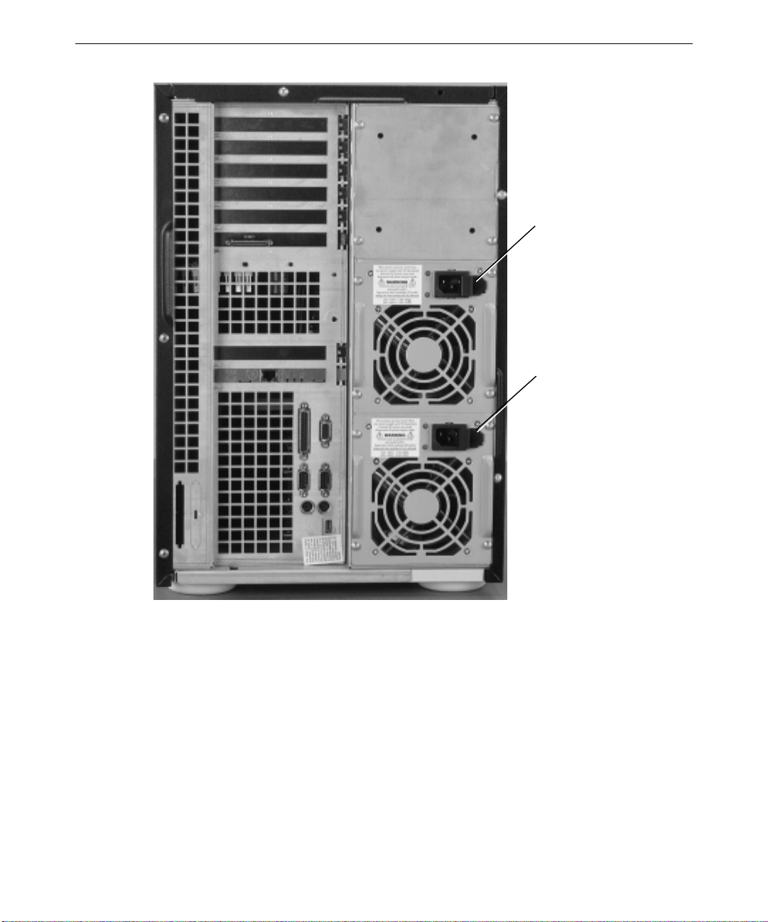
16
AC Receptacle
AC Receptacle
5. If using an AC distribution box or UPS, connect its power cord to a grounded, three-
prong AC power outlet.
NOTE The UPS starts automatically when its power cord is connected to the power outlet. Refer to
the UPS documentation for more details.
6. Connect other cables as necessary for printers (parallel port), external SCSI devices
(SCSI port), and modems or UPS communication (serial ports).
7. Install the disk drives as described in the next section.
Page 27
Installing Non-RAID and RAID Disk Drives
Filled-in Label
Depending on the configuration, the system is non-RAID (also called JBOD, for “just a
bunch of disks”) or RAID. A RAID (redundant array of independent disks) system uses a
1-channel Mylex RAID controller (also called a RAID adapter) to provide RAID capabilities
such as disk striping, mirroring, and redundancy. The non-RAID system use a 2-channel
Ultra Wide SCSI controller that does not feature RAID capabilities.
The disk drive section in the front of the system contains six drive slots. The slots number 1
to 6, starting with the top slot for deskside systems. For rack-mount systems, slot number 1
starts with the left-most slot). If you are installing less than six drives in the system, install
the disk drives starting in slot 1 and fill each slot in sequence.
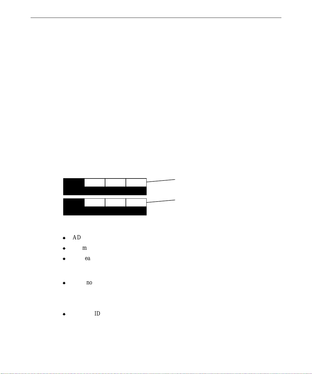
Each disk drive has a label to identify the drive. The left side of the label shows the disk
drive size (in GB). The label has spaces to further identify the adapter (ADP), channel (CH),
and SCSI ID (ID). Standard disk drives include values for the adapter, channel, and SCSI
ID filled in.
NOTE A labeling sheet is included in the system parts box.
17
x GB
x GB
ADP
ADP
CH ID
CH ID
100
Blank Label
Additional disk drives have a blank label which you must complete after installation.
u
ADP means the RAID controller number connected to the RAID section.
u
CH means the RAID SCSI bus channel of the adapter.
u
ID means the SCSI identification number of the drive slot.
Note the following about non-RAID and RAID disk drives.
u
For a non-RAID system, one disk drive (with the operating system installed) is standard.
This drive is called the boot drive. It is labeled with specific adapter, channel, and SCSI
ID. The boot drive should be installed in the lowest slot of the disk section. Installation
details are provided below.
u
For a RAID system, one RAID controller and three disk drives (with the operating
system striped across all three) are standard. These drives, called boot drives, are
labeled with specific adapter, channel, and SCSI ID. They must be installed in specific
slots in the disk section. Installation details are provided below.
Page 28

18
Install and Label the Disk Drives
The following procedures cover both non-RAID and RAID installations. To install the
drives, you must access the sides of the disk drive housing. Drives are hard mounted in the
drive carrier using four screws (two on each side) for each drive. The drive section is behind
the locked door. The key is provided in the parts box.
To install the disk drives:
1. Unlock and open the front door of the base unit.
2. Open the disk section door. The following figure shows the RAID disk section.
Slot 1
3. Remove the disk drives from the drive boxes.
4. Do the following when inserting drives into the slots:
−
Extend the latching clips on the drive and align the rails on the side of the drive
with the slot guides. The metal casing of the drive faces up. If you install the drive
reversed, it will not connect to the system.
−
With your thumb, firmly push the drive in the middle between the latching clips
until it slides all the way into the slot and firmly engages the connector.
−
Close the latching clips to lock the drive in the slot.
Slot 6
Page 29
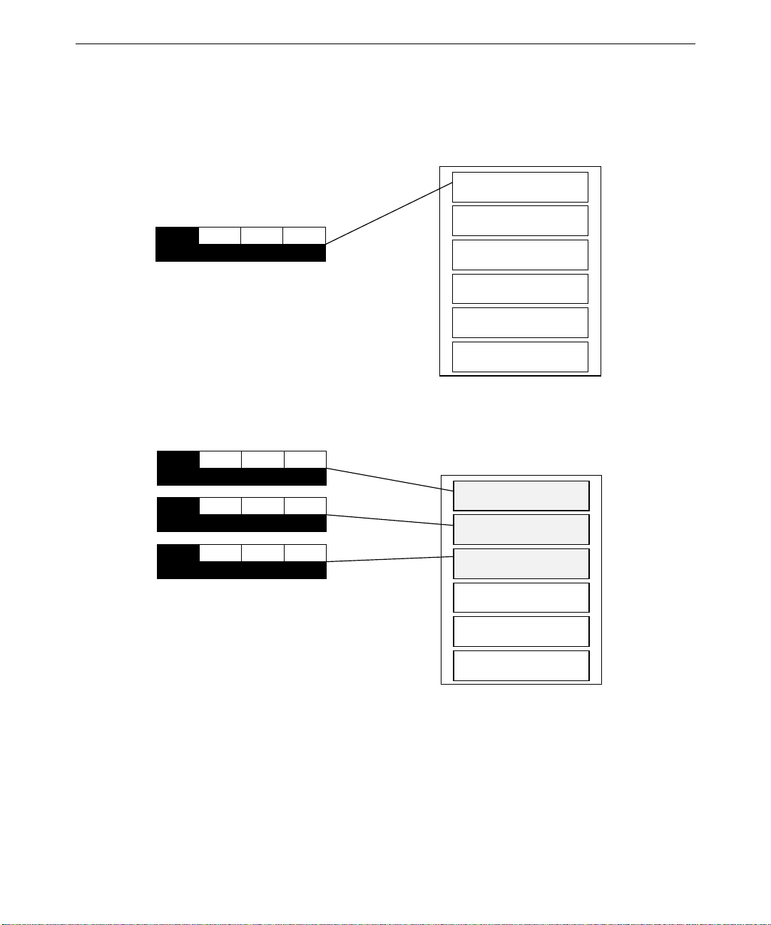
5. Locate and install the boot drives (those with the completed labels).
−
Install the non-RAID boot drive into slot 1 of the disk section, as shown in the
following figure.
Slot 1
Slot 2
x GB
−
ADP0CH0ID
Install the RAID boot drives into slots 1, 2, and 3 of the disk section, as shown in
0
Slot 3
Slot 4
Slot 5
Slot 6
the following figure.
19
x GB
ADP0CH0ID
x GB
ADP0CH0ID
x GB
ADP0CH0ID
0
1
2
Slot 1
Slot 2
Slot 3
Slot 4
Slot 5
Slot 6
6. Install the remaining disk drives into the slots. Fill each slot downward as you install
the drives. There should be no empty slots between the drives.
Page 30
20
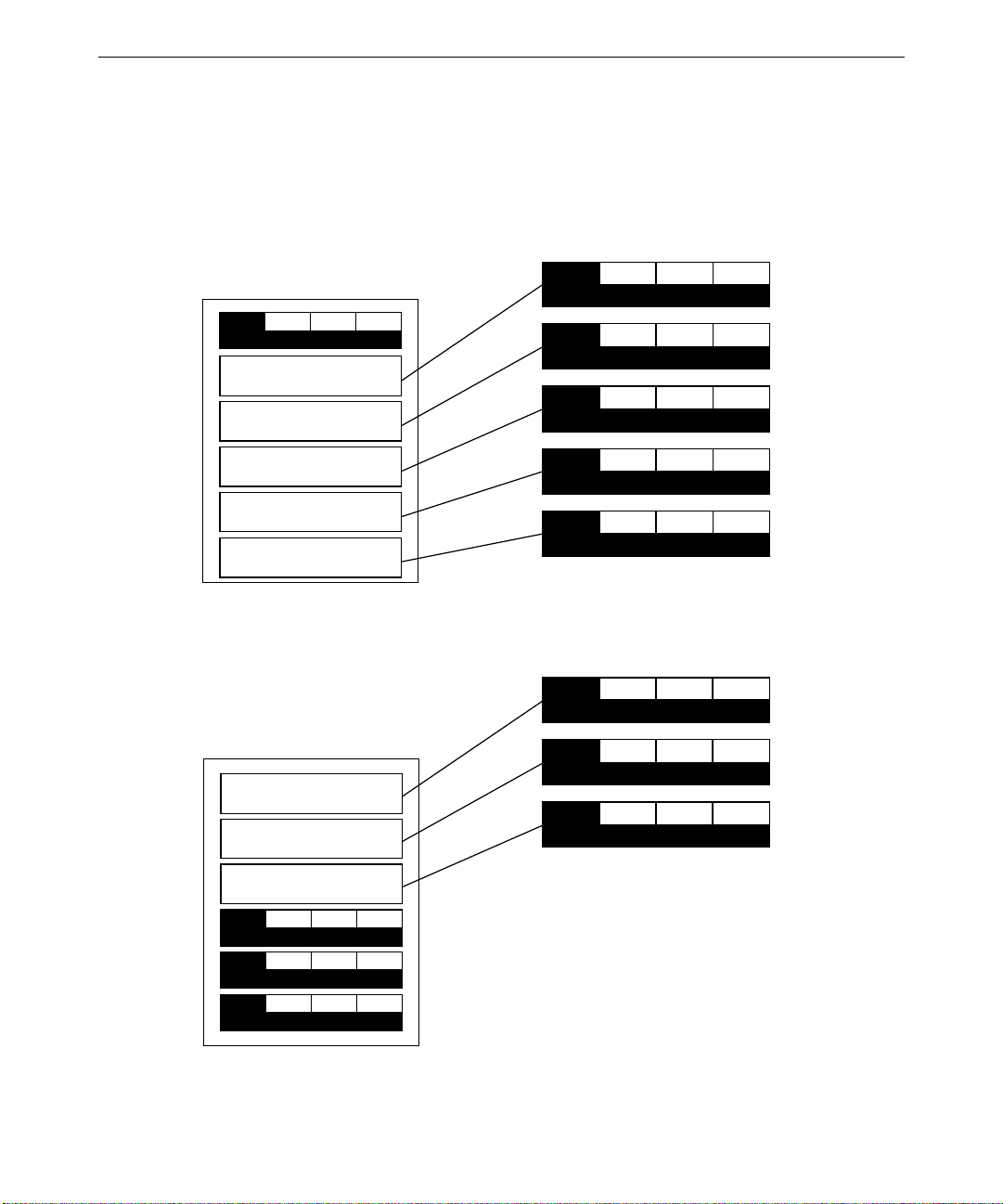
7. Label the remaining disk drives as follows. Note carefully how the drives should be
labeled for each slot.
−
Label non-RAID disk drives with ADP, CH, and ID numbers as shown in the
following figure. For further details, refer to the guide shipped with the hard disk
drive.
x GB
ADP0CH0ID
x GB
ADP0CH
0
x GB
ADP0CH
0
0
1
ID
2
ID
Slot 2
x GB
Slot 3
Slot 4
Slot 5
x GB
x GB
Slot 6
−
Label RAID disk drives with ADP, CH, and ID numbers as shown in the following
ADP0CH
ADP0CH
ADP0CH
0
0
0
3
ID
4
ID
5
ID
figure.
0
1
2
Slot 1
Slot 2
x GB
ADP0CH0ID
x GB
ADP0CH0ID
x GB
ADP0CH0ID
x GB
ADP0CH0ID
x GB
ADP0CH0ID
x GB
ADP0CH0ID
Slot 3
4
Do not use the number 3 from the
5
label sheet for RAID systems. ID 3
is reserved for the disk section
6
backplane.
Page 31

Additional Information
The RAID system boot drives are configured at the factory using Mylex RAID configuration
utilities. Additional disk drives supplied with the system are not configured. You must
configure these drives after configuring system software to make them usable to the system.
Refer to Chapter 3, “Configuring the System,” for more information on configuring and
using the RAID disk arrays.
WARNING Do not turn on the system power until you are ready to configure Windows NT Server.
If you start the system, and then restart it before completely configuring the operating
system, you will have to reinstall system software as described in Chapter 5,
“Reinstalling System Software.”
Checking the System
Before starting the deskside system, review the following items:
u
The cables are properly attached from the base unit to the various options and
peripherals.
u
All disk drives are installed in the proper slots and labeled appropriately.
21
u
The power cord from the system’s AC receptacle is connected to the correct power
outlet.
Before starting the rack-mount system, review the following items:
u
All hardware is properly and securely installed in the rack.
u
The cables are properly attached from the base unit to the accessories installed in the
rack or in remote locations.
u
The cables attached to the server base unit are routed through the cable handler. Ensure
there is enough cable service loop to allow sliding devices to extend 31 inches.
u
The cables that run along the sides or top of the rack are installed in clips or ties to
secure them in place.
u
All disk drives are installed in the proper slots and labeled appropriately.
u
The base unit is retracted into the rack.
u
The power cord from the AC distribution box or UPS is attached to the correct power
outlet.
WARNING Once you install the equipment into the 40 U rack, do not move the rack. If you must
move it, first remove all equipment, move the rack to its new location, and then
reinstall the equipment.
Page 32

22
What’s Next?
You can do any of the following to prepare your system for use:
u
To use Intergraph’s default setup, go to Chapter 2 to start the system and go through
Windows NT Setup. If you start the system, and then turn it off before completing the
instructions in Chapter 2, you will have to reload the operating system and system
software.
u
For RAID systems, the default RAID setup is three disk drives striped to RAID level 5,
including “write through” write policy. The default setup is described in more detail in
the section, “Standard RAID Disk Drives Configuration” of Chapter 3. If you want to
reconfigure the RAID setup, refer to the Mylex documentation.
u
Intergraph Computer Systems installs the operating system through Phase 1 of the
Windows NT Setup process. Phase 2 involves establishing a domain name, determining
a security role, and setting up user accounts. If you want to reinstall the operating
system and system software, instead of completing Phase 2 of Setup, refer to Chapter 5.
Page 33

2 Setting Up the Software
This chapter provides instructions for setting up the system software for the server.
Preparing for Setup............................................................................................................ 24
Pre-Installed Software.......................................................................................... 24
Before You Start Setup......................................................................................... 24
Starting the System............................................................................................................ 26
Starting Operating System Setup........................................................................................ 26
Finishing Operating System Setup ..................................................................................... 27
Creating an Emergency Repair Disk..................................................................... 27
Creating System Software Backup Diskettes......................................................... 28
What’s Next?..................................................................................................................... 28
23
Page 34

24
Preparing for Setup
Your system’s primary system and additional disk drives were formatted and partitioned
before shipment. In Explorer or My Computer, you can right-click a disk drive and click
Properties to display the drive’s partition size and file system format. To view partition and
format information for all disk drives, you can use Disk Administrator. See the operating
system documentation and Help for more information on these tools.
Pre-Installed Software
The operating system and associated system software is pre-installed on the primary hard
disk drive. Intergraph Computer Systems installed the following system software:
u
Driver software for the installed SCSI adapter(s)
u
Driver software for the installed network adapter
u
Driver software for the installed video display adapter
u
Driver software for the installed mouse, if needed
u
InterSite software
u
Quick-Fix Engineering (QFE) update software (fixes for operating system problems or
limitations), if needed
Before Y ou St art Setup
Before starting the Setup process, have the following documentation available:
u
The Microsoft Start Here document
u
Documentation for the video display adapter delivered with the system
Get and record the following information:
u
Your name, and the name of your
company or organization:
u
For a system running Windows NT,
the CD key from the Windows NT CD
case, or the Product ID Number from
Start Here or the registration card:
Page 35

If the system is connected to a network, obtain and record the following information from
your network administrator:
u
Computer name for your system:
u
Workgroup name (if the system will be
part of a workgroup):
u
Domain name (if the system will be part
of a Windows NT domain):
u
Security role for your system in the
Windows NT domain -- primary domain
controller, backup domain controller, or
domain server:
u
If your system will be acting as a backup
domain controller or domain server,
username and password of an authorized
domain administrator account:
NOTE Determine the security role for your server before beginning system configuration. You
cannot change a server to a domain controller without reinstalling Windows NT Server. A
domain controller maintains security policy and performs user authentication for a domain.
Servers may be part of a domain, although they do not have to participate in a domain. See
the operating system documentation for a detailed explanation of the differences between
domain controllers and servers.
25
If the system is connected to a network that uses the Transmission Control Protocol/Internet
Protocol (TCP/IP), get and record the following TCP/IP information from your network
administrator:
u
Internet Protocol (IP) address for your
system:
u
IP subnet mask for your system:
u
IP domain name for your network:
u
IP address for your network’s default
gateway:
u
IP addresses for your network’s
Domain Name System (DNS) servers,
if any:
u
IP addresses for your network’s
Windows Internet Name Service
(WINS) servers, if any:
Page 36

26
The Windows NT delivery media contain software and drivers for both Reduced Instruction
Set Computing (RISC)- and Intel-based systems. When installing Windows NT distribution
files, make sure you install them from the \
delivery media. For example, if you are installing a device driver from the Windows NT
CD-ROM, key in the following when prompted for the path:
drive:\i386
where drive is the drive letter for the CD-ROM drive.
I386 directory (the Intel software directory) on the
Starting the System
The power button is behind the locked door. To start the system, unlock and open the front
door and press the power button on the front of the system. If you have an AC distribution
box connected to the system, make sure its power switch is turned on before you start the
system.
Starting Operating System Setup
When you start your system for the first time, you must configure the operating system
software for use. After you first start the system, the Microsoft End User License Agreement
(EULA) screen displays.
NOTE Before starting the system for the first time, you may want to learn more about system power,
startup, and shutdown. See Chapter 4, “Operating Notes,” for this information.
To start the computer and set up the operating system software:
1. Turn on the monitor by pressing its power switch.
2. Press the power button on the front of the system. The system starts and the EULA
screen displays on the monitor.
3. Read the terms of the EULA and then follow the instructions displayed on-screen to
complete the Setup process. A Welcome screen displays, then a prompt for user and
organization, and then a prompt for the product ID. Accept the default settings provided
by Setup, except as follows:
−
Setup asks if you want to install networking. If you choose to install networking
(default), choose “Select from list...” when prompted whether to allow Setup to
detect the network adapter. From the list, select “3Com Fast Etherlink XL Adapter
(3C905).” Allow Setup to install this driver software.
Page 37

−
Create an Emergency Repair Disk when prompted.
−
Enter a password for the Administrator account when prompted.
After you configure networking, you can join a workgroup or domain. You cannot set up a
user account until after you have completed setup and rebooted the system. See Windows
NT Help for details on setting up a user account and joining a workgroup or domain.
Finishing Operating System Setup
After operating system Setup is completed, a “Press to finish setup” icon displays on the
operating system desktop. Double-click this icon, or select Programs/InterSite/Welcome
from the operating system Start menu, to display InterSite Welcome.
InterSite Welcome helps you do the following:
u
Create a repair disk for the operating system.
u
Create backup diskettes of device driver software and other system software products.
u
Get the latest driver and other system software from the World Wide Web.
27
u
Display an online System Introduction for your system.
u
Learn about Intergraph Computer Systems customer support.
You should take advantage of the tools provided by InterSite Welcome to ensure that your
system is fully ready for use. See InterSite Welcome for more information. Also see the
following sections for information on creating an Emergency Repair Disk and creating
backup diskettes.
Creating an Emergency Repair Disk
If you did not create an Emergency Repair Disk during Setup, use the tools provided by
InterSite Welcome to do so. See the operating system documentation and Help for
information on creating an Emergency Repair Disk. You should also update an Emergency
Repair Disk after you finish configuring the system.
In the event of corrupted disk drives, the files on the repair diskettes restore the contents of
the operating system registry at the time the operating system was installed, along with the
standard operating system drivers.
Page 38

28
Creating System Software Backup Diskettes
Backup media for some device driver software and system software products may not be
delivered with the system. Use InterSite Version Manager, available through InterSite
Welcome, to create system software backup diskettes.
Version Manager lets you create backup diskettes containing device driver software and
system software products that were installed on the system before shipment, and which are
not available on the operating system CD-ROM. You may need these backup diskettes later
-- for example, if you have to reinstall a device driver or the operating system.
NOTE InterServe products are delivered with backup media of all drivers and other system software
products.
NOTE You may not have to create backup diskettes for all system software. If Version Manager
does not list drivers or other system software products, then they are available on the
operating system software CD, or on backup media delivered with the system.
If the system requires Quick-Fix Engineering (QFE) update software, it is included in the
system software available for backup diskette creation. QFE update software contains fixes
for operating system problems or limitations, and is only shipped with the system if it is
needed. If QFE update software is shipped with the system, you should create a QFE backup
diskette for use if you have to reinstall the operating system. See the
QFE diskette for information on the applicability and installation of QFE update software on
your system.
README.TXT file on the
See Version Manager Help for information on creating system software backup diskettes.
Visit the Intergraph Computer Systems site on the World Wide Web and vendor bulletin
boards for new and updated drivers.
What’s Next?
See the online System Introduction for information on system features and controls.
See Chapter 3, “Configuring the System,” to configure the system for use.
See Chapter 4, “Operating Notes,” for related details.
Page 39

3 Configuring the System
Follow the instructions in this chapter to configure the InterServe 9000 for use.
Configuring the Video Display........................................................................................... 30
Changing the Default Video Display Driver ......................................................... 30
Correcting Video Display Problems...................................................................... 30
Installing Mylex RAID Software........................................................................................ 31
Configuring Drives for a RAID Disk Array........................................................................ 32
Standard RAID Disk Drives Configuration........................................................... 32
Additional RAID Disk Drives Configuration........................................................ 35
Installing and Configuring LanSafe UPS Software............................................................. 36
Installing QFE Update Software......................................................................................... 37
Installing Intel Server Control (ISC) Software.................................................................... 37
Creating an Emergency Repair Disk .................................................................................. 37
Getting Operating System Updates..................................................................................... 37
29
Page 40

30
Configuring the Video Display
The first time you start the system, it uses the installed video display adapter running at
1024 x 768 to run the video display. For the system to use the installed video adapter at
other display resolutions, you must configure the video display driver. Refer to the
documentation delivered with the video display adapter for information about available
settings. For information on using the Display Properties dialog, refer to the operating
system documentation and Help.
Changing the Default Video Display Driver
After configuring the video display and restarting the system, you should configure the
system to use the Intergraph video display driver by default.
To change the default video display driver:
1. Open System in the Windows NT Control Panel. The System dialog displays.
2. Under Operating System, select the Startup list; then select the appropriate non-VGA
Windows NT Server option from the displayed list.
3. Select OK.
Correcting Video Display Problems
If the system’s video display is black, not synchronized, or distorted after you restart the
system, you may have a video configuration problem.
Do not press
correct the problem by using the Last Known Good option to return the system to the last
known good configuration recorded by Windows NT.
To use the Last Known Good option:
1. Power down and restart the system.
2. Press the space bar at the following prompt:
Press space bar NOW to invoke the Last Known Good Menu
If using the Last Known Good option fails to correct the video display problems, you can
obtain a functional video resolution by restarting the system in VGA mode.
CTRL+ALT+DEL to log on to the Windows NT operating system. Instead, try to
Page 41

To restart the system in VGA mode:
1. Power down and restart the system.
2. At the boot screen, select the VGA mode option.
After logging on to Windows NT in VGA mode, check for the following common
configuration problems and solutions:
u
A multi-sync monitor is selected, but a graphics display device with different video
timings (such as an Intergraph InterVue monitor) is connected to the system. Select the
appropriate monitor type as described previously.
u
The monitor selection is inappropriate for the monitor connected to the system. Select a
new monitor.
u
There is not enough video display memory to support the selected graphics resolution
and color depth. Install and reconfigure the video display to use a lower resolution and
color depth.
Restart the system and, when the boot screen displays, select the appropriate non-VGA
Windows NT Server to use the reconfigured video display driver. If problems persist,
contact the Intergraph Customer Response Center at 1-800-633-7248 for help.
31
Installing Mylex RAID Software
Mylex RAID software is installed at the factory on RAID systems. If you have to reinstall
the operating system and associated system software, you must reinstall the Mylex RAID
software after configuring the operating system. Install the software from the backup
diskette supplied with the system, or from the backup diskette you created using Version
Manager. Refer to Version Manager Help for more information about using Version
Manager.
NOTE The MYLEXPCIDRV product contains some administrative utilities for use with the Mylex
software. See the
of these utilities.
To install Mylex software:
1. Log on to Windows NT using an administrative account.
2. Insert the diskette containing the Mylex RAID software in the system’s floppy disk
drive.
3. Run
SETUP.EXE on the diskette.
4. Respond yes or no appropriately to the questions about Windows NT. At the Welcome
dialog, select Next. The Mylex Install Destination Path dialog displays.
README.TXT in the product directory for instructions on installation and use
Page 42

32
5. If you agree with the destination directory, select Next. Otherwise, select Browse and
enter a new directory path. The files will be copied and a Mylex program group created.
Setup also displays a message that the driver is present on the system.
For information on configuring and using the RAID disk drives, and for information on
using the Mylex RAID controller, refer to the Mylex documentation delivered with the
system.
Configuring Drives for a RAID Disk Array
NOTE This section only applies to systems that use RAID disk drives. For technical information
about the disk drive section, refer to the
This section explains the standard RAID disk configuration and provides guidelines to
configure additional RAID drives. The standard RAID hardware is pre-configured by
Intergraph Computer Systems before shipment. The following information is provided to
help you understand how RAID is implemented, which should be valuable if you need to
configure additional RAID hardware.
Standard RAID Disk Drives Configuration
System Reference
.
The InterServe 9000 systems contain three main RAID hardware components:
u
An internal disk section
u
Three or more RAID disk drives
u
One or more RAID controllers (adapters)
The RAID disk drives are installed in slots 1, 2, and 3 of the disk section. These three drives
are grouped (packed) into one array. This array appears as a single drive in Windows NT
Disk Administrator, at double the size of one of the drives. For example, three 4 GB disk
drives appear as an 8 GB logical drive if the RAID level is set to RAID 3 or RAID 5 (12 GB
if the RAID Level is set to RAID 0). RAID 5 is the default.
The Mylex RAID controller BIOS and the Mylex RAID configuration utility let you view
and change the way in which the RAID controller treats the RAID drives. For example, you
can change the configuration so that each drive is a separate array, instead of all three being
in one array.
The following figure shows the correlation between the disk drives (labeled), their slot
location (shaded areas), and how they are identified in Mylex BIOS and the Mylex utility.
Page 43
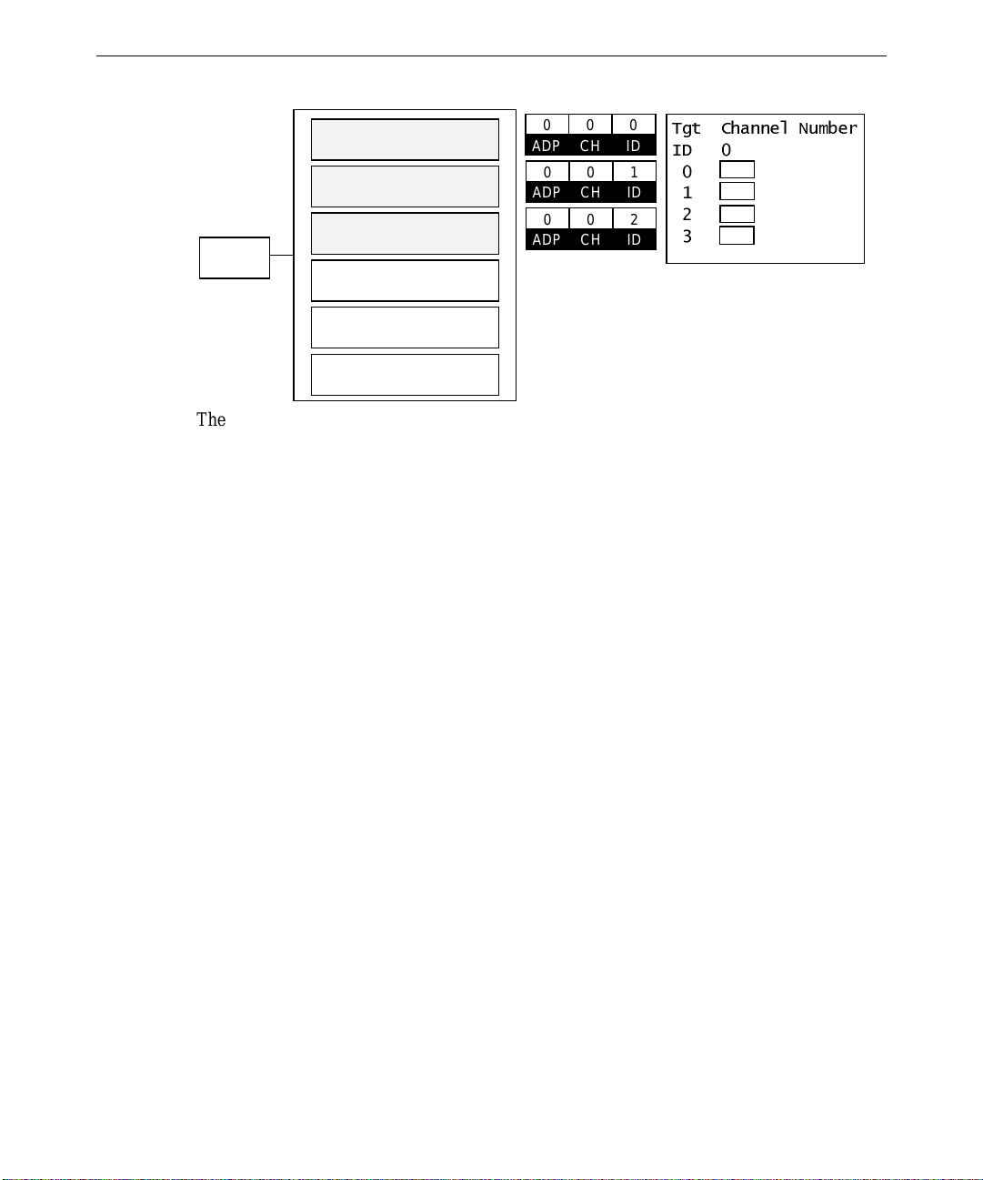
33
ADP
ADP
ADP
ADP 0
Slot 1
Slot 2
Slot 3
Slot 4
Slot 5
Slot 6
SCSI ID 0
SCSI ID 1
SCSI ID 2
SCSI ID 4
SCSI ID 5
SCSI ID 6
0CH0ID0
0CH0ID1
0CH0ID2
7JW&KDQQHO1XPEHU
,'
Mylex IDDisk L ab el
The non-volatile memory and flash EEPROM on the RAID controller board stores the
configuration data. When you restart the system, the RAID controller uses this information
to define the RAID configuration to the operating system.
Throughout the Mylex RAID configuration utility, a banner at the top of the display shows
the title, version number, date, controller name, slot number, and firmware version. The
bottom of the display indicates the actions you can take for each menu option. Additionally,
information boxes describe possible actions not allowed. Warning boxes display when the
next action could destroy data on the drives, erase configurations, or has other serious system
consequences.
The following table defines the terms you will see while running the Mylex RAID
configuration utility to configure the drives.
RDY Disk drive ready for configuration
CDR CD-ROM drive
TAP Tape drive
UNF Unformatted drive
PAK Configured packs
DRVS Number of drives in a pack
SIZE Size of the packs (in megabytes)
ONL Drive online (part of pack)
DED Failed drive
RBD Rebuilding
WRO Rebuilding (write only)
FMT Formatting
SBY Standby drive
Page 44

34
The default RAID configuration for the three standard RAID drives is as follows:
u
RAID level - 5
u
Write policy - write through
u
Device Spinup - two drives every 12 seconds
u
Ultra SCSI - enabled
If you modify the RAID configuration, and want to return to the default settings, use the
following procedure.
To reset the default RAID configuration:
1. Reboot the system.
2. When prompted, press
ALT+R to enter the Mylex RAID configuration utility. The Main
Menu displays.
MYLEX Disk Array Controller-Configuration Utility Version X.XX X/XX/XX
2 Channel - 7 Target DAC960P #1 Firmware version x.xx
Main Menu
01. Automatic Configura tion
02. New Confi guration
03. View/Upda te Configu ratio n
04. Rebuild
05. Initializ e System D rive
06. Consisten cy Check
07. Tools
08. Select DA C960
09. Advanced Functions
10. Diagnosti cs
If more than 3 Physical Driv es ar e pre sent , choose t his
option to cre ate one RA ID 5 Syste m Dri ve a utomatical ly.
Use cursor keys for selection, hit <ENTER> to select, <ESC> to Quit
The Help window (box below the Main Menu) briefly describes the operations you can
perform with the highlighted option. Use the cursor keys to select the options in the
Main Menu and press
ENTER to select the highlighted option.
3. Move the cursor down and select New Configuration to set up one 8 GB array to RAID
level 5, and “write through” write policy.
4. Restart the system.
Page 45

Additional RAID Disk Drives Configuration
The Mylex RAID controller BIOS manages up to eight disk drives. If a system has more
than eight drives configured across multiple RAID controllers, you must ensure that the
RAID disk drive containing the operating system (boot drive) is recognized during the BIOS
scan sequence. The BIOS scan sequence starts with the internal devices and then moves to
the PCI slots in the following order: A1, A2, A3, B1, B2, B3, B4. The operating system
boot device must be attached to the RAID controller that is seen first during the scan of the
PCI slots. See the System Reference for more information.
If your system was shipped with more than three RAID drives, then the extra drives are not
configured. Before you can use them, the additional RAID drives must be configured into
one or more arrays using the Mylex RAID controller BIOS or the Mylex RAID configuration
utility. The following steps provide the general guidelines; see the Mylex documentation for
detailed instructions.
To configure additional drives:
1. Reboot the system.
35
2. When prompted, press
ALT+R to enter the Mylex RAID configuration utility. The Main
Menu displays.
3. Select the RAID controller to which the unconfigured RAID drives are connected.
4. From the Main Menu, select View/Update Configuration, then use this option to make
additions to the configuration. This allows you to retain the existing configuration and
create new drive groups. See the Mylex documentation for details.
5. Select the unconfigured RAID drives (shown as RDY) and configure them into one or
more arrays as desired.
CAUTION Do not place different size drives into the same array. If you do, the size of the larger drives
will be truncated to that of the smaller drives, and the remainder will be unusable.
6. When the configuration has been applied, set the drive options to your desired settings.
7. Once all of the RAID drives are defined, press
ESC twice, and then select YES to save
the configuration.
8. From the Main Menu, select Initialize System Drive. Follow the instructions in the
Mylex documentation to mark a system drive and then intialize the drive.
Preparation of the array is complete at this point. You can exit the Mylex RAID
configuration utility and reboot the system. The new RAID pack appears as unpartitioned
disk space under the Disk Administrator utility. You must partition and format the disk
drive space.
Page 46

36
Installing and Configuring LanSafe UPS Software
Systems equipped with a uninterruptible power supply (UPS) are shipped with LanSafe III
software to configure and monitor operation of the UPS. The software must be installed
before you can configure and monitor UPS operation. The following instructions assume
that you are installing LanSafe III UPS software on your system for the first time.
To install LanSafe III UPS software:
1. Insert the LanSafe III CD-ROM into the CD-ROM drive.
2. Run
3. When the Welcome dialog displays, select Install.
4. Select Full Installation to install the software onto the server. If you are installing the
NOTE If you select Install remote services only, Setup asks for a location to install the files. Select
the default location, or enter an alternate pathname; then select Continue. After the software
is installed, click OK and restart the system.
5. When asked if the computer is part of a UPS group, select No; then select Continue.
6. Select Power Rite Pro II; then click Continue.
7. Select the COM port to be used; then select Continue.
8. Enter an access code to safeguard the UPS operation; then select Continue.
9. Select Shutdown Timing Operations; then select Continue.
10. Select Yes for the Automatic Load Option; then select Continue.
11. A dialog asks for a location to install the files. Accept the default location, or enter an
12. Select LanSafe III Power Monitor Service and click Startup. The Service dialog
SETUP.EXE in the NTWIN directory on the CD-ROM drive.
remote services on a non-UPS system, select Install remote services only; then select
Continue.
alternate pathname; then select Continue. When the software is installed, open the
Control Panel and double-click Services. The Services dialog displays.
displays. Verify that the Allow Service to Interact with the Desktop check box is
selected.
13. Click OK to close the Service dialog, and click Close.
14. Shut down the system.
15. Verify that the serial cable is connected as described in the LanSafe III software manual,
and that all AC power cables are connected to AC receptacles on the back of the UPS.
16. Restart the system.
Refer to the LanSafe III documentation for instructions on using the LanSafe III software.
Page 47

Installing QFE Update Software
If the system was shipped with Quick-Fix Engineering (QFE) update software, you can
create a QFE diskette using Version Manager. QFE update software contains fixes for
operating system problems or limitations on your Intergraph system, and is only shipped
with the system if it is needed. If you have a QFE diskette, insert it into the floppy disk
drive. See the
installation of QFE update software on your system.
README.TXT file on the QFE diskette for information on the applicability and
Installing Intel Server Control (ISC) Software
ISC is the InterServe 9000 onboard instrumentation software that can be used as a
standalone package or with the Intersite Server Monitor Product. ISC must be installed to
view instrumentation data. See the system software CD for installation instructions.
Creating an Emergency Repair Disk
You should create an Emergency Repair Disk after you finish configuring the system. The
files on the Emergency Repair Disk can restore a damaged registry to its original contents
(that is, at the time Windows NT was installed), along with the standard Windows NT
drivers.
37
Use the
to update the Emergency Repair Disk any time you change the system’s configuration. You
should also make and keep a backup copy of the Emergency Repair Disk.
Refer to the operating system documentation and Help for information on creating and using
an Emergency Repair Disk.
RDISK.EXE utility to create an Emergency Repair Disk. You can also use this utility
Getting Operating System Updates
Microsoft Service Packs and Service Releases contain the latest improvements and system
fixes for Microsoft operating systems. Service Packs and Releases are created by Microsoft
for post-release support. You can get them from Microsoft’s World Wide Web and FTP sites
free of charge.
CAUTION If Intergraph Computer Systems provides a Service Pack through the IBBS or with a product,
it has been certified against Intergraph hardware as described in the announcement of its
availability. If you obtain a Service Pack from any other source, be aware that it may not be
certified against your Intergraph hardware.
Page 48

38
Page 49

4 Operating Notes
Now that your system is up and running, and all the software is configured, use this chapter
to become familiar with the InterServe 9000 and its user features.
Starting and Stopping the System ...................................................................................... 40
System Status LEDs........................................................................................................... 41
Disk Drive Status LEDs (RAID Systems)........................................................................... 42
System Alert...................................................................................................................... 42
Using InterSite Programs................................................................................................... 43
Additional User Information .............................................................................................. 43
What’s Next?..................................................................................................................... 44
39
Page 50
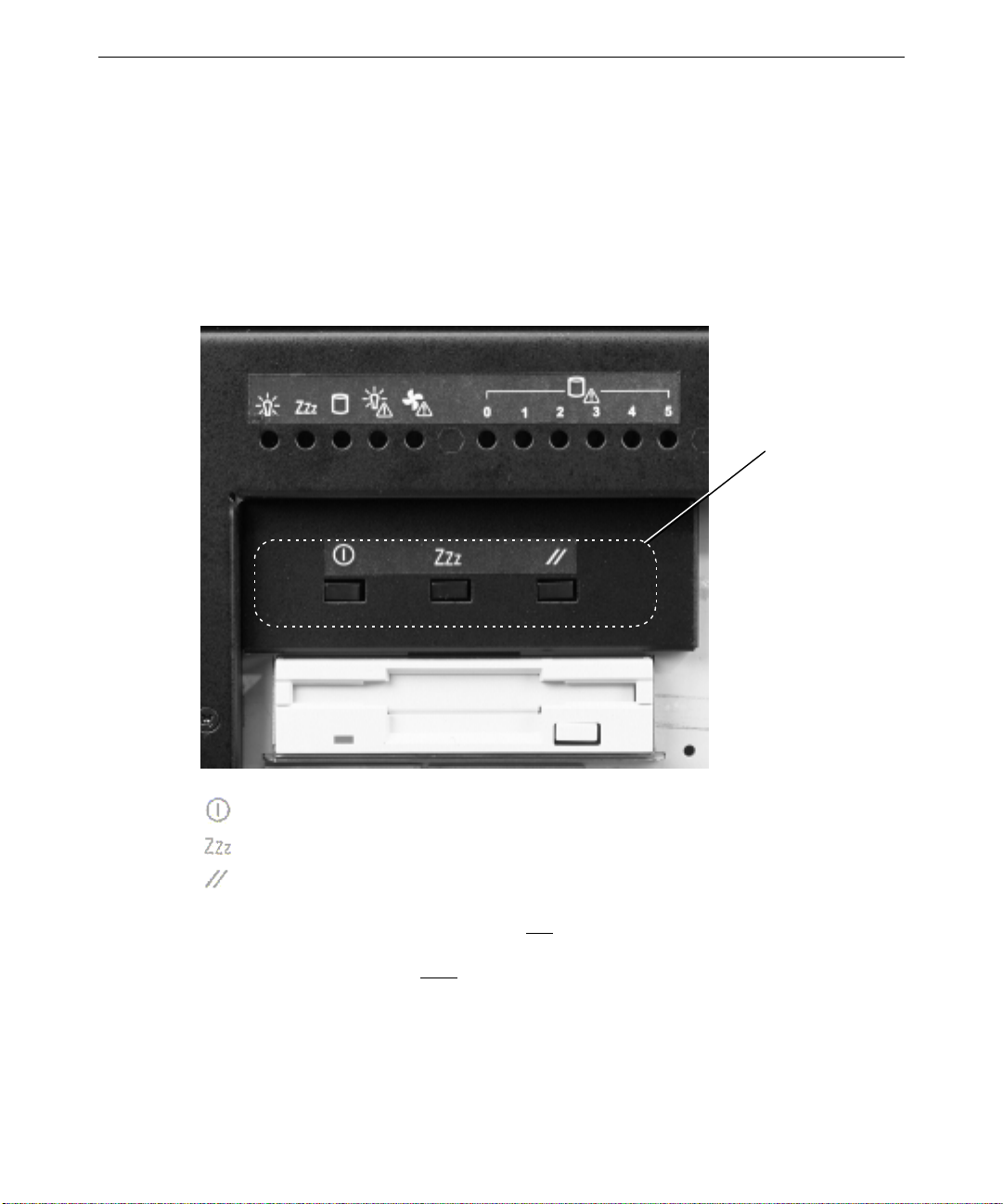
40
Starting and Stopping the System
After the system is running, you can restart the system, or shut it down and power it off
completely. Wait at least 30 seconds before restarting the system to allow the InterSite
software to function correctly, the power supplies to stabilize, and the disk drives to stop
spinning.
The following figure shows the system control buttons.
Buttons
Power button
Sleep/Service button
Reset button
Holding down the Sleep/Service button for less than four seconds enters sleep mode, which
requires an Advanced Configuration and Power Interface (ACPI)-compliant operating
system. Holding it down for more than four seconds enters service mode, which powers
down the electronics bay but leaves hot-swap and peripheral bays running.
Pressing the Reset button clears system memory, restarts power-on self-test (POST), and
reloads the operating system.
Page 51

To stop the system, perform an orderly shutdown and then press the power button. An
orderly shutdown consists of stopping all running applications and logging off Windows NT
by clicking on Start on the display screen and then selecting Shutdown.
If external InterRAID disk cabinets are connected to the system, always power the system on
or off as follows:
u
Turn on power to the InterRAID cabinets first, listen for the audible beep, and then turn
on power to the system base unit.
u
Turn off power to the system base unit first (as described previously), and then turn
power off to the InterRAID cabinets. If you turn off power to the InterRAID cabinets
first, the RAID controller will read the drives in those cabinets as dead the next time you
power on the system. If this happens, refer to the Mylex documentation for drive
recovery procedures.
System Status LEDs
The Light-Emitting Diodes (LEDs) on the front of the system help you determine system
status at a glance. If any of the LEDs are amber, there is a problem in part of the system
hardware. If the fan status LED is amber and the power supply status LED is green, it is
possible that the problem is a fan inside the power supply, rather than a main cooling fan.
41
The following figure shows the location of the system status LEDs.
System
Status
LEDs
System Power - green when power is on, off otherwise.
Sleep/Service - flashing green in service mode.
Hard Drive Activity - green if hard drive is active.
Power Supply Fault - amber if power supply failure.
Fan Fault - amber if fan failure.
Page 52
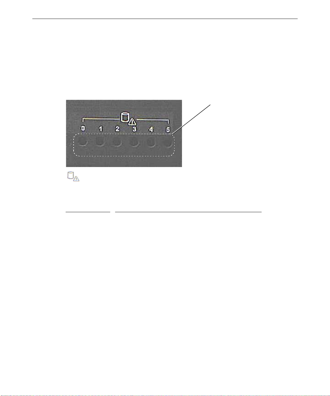
42
Disk Drive Status LEDs (RAID Systems)
On RAID systems, additional disk status LEDs coincide with each slot of the RAID disk
section. The disk status LEDs, labeled 0-5 on the front panel, indicate hard disk drive or
array status for each of the installed drives. They function only if the system uses RAID
drives. They indicate a failure condition (amber) if a problem occurs in the system or
internal RAID, and an alarm sounds a continuous beep.
RAID
Disk Drive
Status
LEDs
Hard Drive Fault - green if OK, amber if otherwise.
The following table shows the status indications for disk drives in a RAID system.
LED Color
Steady amber Disk drive rebuild in progress, or critical (degraded) array
Blinking amber Disk drive failed
Off Disk drive not installed or not seated
Sy stem Aler t
To ensure system security, the InterServe includes a system alert that detects and reports
hardware faults such as power supply failures. Also, conditions that may lead to component
failure, such as excessive room temperature, are detected. Intrusion alert applies only for the
top cover (if rack-mounted) or left side cover (if deskside). There is no intrusion alert for the
front panel or disk drive door.
You can configure the InterSite Server Watchdog software to notify you if an alert is
triggered. When a hardware fault occurs, the system alert sounds an alarm. Refer to the
printed and online documentation delivered with the InterSite Watchdog software for more
information about notification.
Meaning
Page 53

Using InterSite Programs
InterServe 9000 systems ship with the following InterSite programs:
u
InterSite Version Manager is a tool for creating system software backup diskettes, and
for updating device drivers and other system software products installed on the system.
u
InterSite DMI Console gives easy access to the system’s status and configuration
information. The Console is based on the Desktop Management Interface (DMI),
through a window containing a graphical information tree view pane, a service provider
component information pane, and a message pane. DMI Console works with the
Desktop Management Interface (DMI), a technology standard that enables the effective
management of personal computers (PCs).
u
InterSite Watchdog is a system monitoring tool with remote monitoring capabilities.
You can install Watchdog on a system running Windows NT, and use it to monitor
workstations and servers also running Windows NT.
From the operating system Start menu, go to Programs/InterSite to find the InterSite
programs on your system. See the online Help for each InterSite program for more
information on how to use the program.
43
Additional User Information
User information for the following hardware is provided in separate documents, delivered
with the system.
u
RAID or SCSI controller
u
Networking card
u
Uninterruptible Power Supply
u
Concentrator
u
Keyboard
u
Pointing or tracking device
Additional technical information about the system is included in the System Reference
document.
If the system came with an Intergraph rack, refer to the documentation delivered with the
rack and other rack-mounting equipment for information and safety precautions related to
using the system in a rack.
Page 54

44
What’s Next?
See the System Reference for information to configure the BIOS. It describes how to use
BIOS Setup to configure the system BIOS. The System Reference also has troubleshooting
information to resolve common system problems.
Page 55

5 Reinstalling System Software
Follow the instructions in this chapter only if you have to reinstall the operating system and
associated system software on the system.
CAUTION Before you reinstall system software, read and understand the entire chapter.
Before You Begin.............................................................................................................. 46
System Software Products.................................................................................................. 46
Installing Windows NT Server 4.0 on Systems with 3 GB of Memory or Less.................... 48
Installing Windows NT Server 4.0 on Systems with More Than 3 GB of Memory.............. 49
Getting Operating System Updates..................................................................................... 52
45
Page 56

46
Before You Begin
Have the following items available:
u
The information you recorded in Chapter 2, “Setting Up the Software.”
u
Operating system software CD-ROM, associated diskettes, and documentation. Make
sure you have the Setup diskettes delivered with the operating system. If your system
has more than 3 GB of memory, be sure you have the 4
you will use in place of the setup diskettes delivered with the operating system.
u
Backup diskettes you created according to instructions in Chapter 2, “Setting Up the
Software,” or which were delivered with the system.
NOTE Backup media for products such as InterSite is delivered on the System CD.
u
Backup media and documentation delivered with any option cards or additional
peripheral devices purchased from Intergraph.
u
The Late-Breaking News document delivered with your system, if applicable.
GB_NTSSETUP diskettes, which
NOTE On a system with Windows NT Terminal Server, refer to the
Breaking News
instructions.
and the
Windows Terminal Server Start Here
Windows Terminal Server Late-
document for installation
You can find the system software on diskettes or CD-ROM provided by Intergraph or on the
operating system CD-ROM. If you did not create backup diskettes of drivers or other system
software products, they are probably available on the operating system CD-ROM or on
backup media delivered with the system.
Driver software is routinely improved and updated. Visit the Intergraph Computer Systems
site on the World Wide Web and vendor bulletin boards for new and updated drivers.
Review the Late-Breaking News document delivered with your system for any additional
tasks you may have to perform during installation.
System Software Products
If a system software product is not listed in the following table, but is installed on your
system, the product is available from an operating system software CD-ROM, or is delivered
with an expansion board or additional peripheral device.
NOTE You received an Option Pack CD and you may have received a Service Pack CD. Service
Pack 3 software can be installed from the Option Pack CD. If you have both CDs and choose
to install both, be sure to install the Service Pack 3 software first, then Option Pack, and then
the later Service Pack.
Page 57

The following table lists drivers and other system software products typically installed on
InterServe 9000 systems.
47
Product
4GB_NTSSETUP Windows NT Server 4.0 Setup
Description Delivery Method
Diskette
diskettes modified to support
systems with more than 3 GB
physical memory
3COM3C90X 3COM 3C905 driver Version Manager and diskette
or CD
MYLEXPCIDRV Mylex RAID driver and utilities Version Manager and diskette
or CD; with RAID systems
only
CIRRUSNTDRV Cirrus 5480 graphics display driver Version Manager and diskette
or CD
LMOUSE Logitech mouse driver Version Manager and diskette
or CD
QFE* Quick-Fix Engineering Update post-
Service Pack hotfixes. Review the
Version Manager and diskette
or CD
README.TXT in any QFE product
delivered with your system to see if
it applies to your configuration.
SYMSCSI Symbios SCSI driver Version Manager and diskette
or CD
SYMLVDSCSI Symbios LVD SCSI driver Version Manager and diskette
or CD
9000IN System Introduction Online Help Version Manager and diskette
or CD
DMI InterSite Desktop Manager Interface Version Manager and CD
IM InterSite Manager Version Manager and CD
VERMANAGER InterSite Version Manager Version Manager and CD
WATCHDOG InterSite Watchdog Version Manager and CD
WELCOME Welcome Utility Version Manager and CD
FLASHNX Flash Program Utility IBBS and Intergraph Online
Page 58

48
Installing Windows NT Server 4.0 on Systems with 3 GB of Memory or Less
Use this section to install Windows NT Server 4.0 if your system has 3 GB of memory or
less. If your system has more than 3 GB of memory, see “Installing Windows NT Server on
Systems with More Than 3 GB of Memory.”
CAUTION If your system is equipped with an internal RAID section or an external RAID disk array, and
your system drive is part of the RAID set, you must select the RAID level and configure the
RAID before you start Windows NT Setup and install Windows NT Server. Refer to the Mylex
documentation for instructions on configuring the RAID disk array. Then return to this
document and install Windows NT Server.
To install Windows NT Server on systems with 3 GB of memory or less:
u
Follow the instructions in Start Here to install Windows NT, and do the following steps
as you install the operating system:
1. Select Custom Setup.
2. Press
F8 to accept the End User License Agreement (EULA).
3. When prompted to detect mass storage devices, press S to skip automatic detection,
then press S to install the SYMSCSI driver from backup diskette. Press S again to
install SYMLVDSCSI. If you have a Mylex RAID based system, press S to install
the MYLEXPCIDRV driver from backup diskette.
4. You can safely select the default responses for other options in Setup except when
installing networking. When prompted to select a network adapter, click Have
Disk. Insert 3COM3C90X disk 1 and click OK. From the list, select 3Com Fast
Etherlink XL Adapter (3C905) and press
ENTER. Follow the instructions on screen
to complete network installation.
5. Create an Emergency Repair Disk when prompted.
After installing the operating system:
u
Restart the system.
u
Install the InterSite software products from the System CD. Insert the System CD and
follow the instructions displayed in the System CD window.
u
Configure the system as described in Chapter 3, “Configuring the System.”
u
Perform any additional installation and configuration tasks described in the LateBreaking News document delivered with your system.
Page 59

49
Installing Windows NT Server 4.0 on Systems with More Than 3 GB of Memory
CAUTION If your system is equipped with more than 3 GB of memory, you cannot install Windows NT
Server 4.0 unless you do one of the following:
NOTE These processes are not necessary for installing Windows NT Server, Enterprise Edition 4.0
or Windows NT Server, Terminal Server Edition 4.0. These processes are only necessary if
you install Windows NT Server 4.0.
u
Remove one memory DIMM from the base unit. You must remove the DIMM residing
in slot J16 of the last bank (highest). Follow the instructions in the System Reference to
access the DIMM memory modules. Remove only the DIMM from slot J16. Close the
base unit, turn on system power, install Windows NT Server following the instructions
in “Installing Window NT Server 4.0 on Systems with 3 GB of Memory or Less,” and
then install Service Pack 3 or later. After the system boots properly, turn off system
power and reinstall the DIMM in slot J16.
u
If you do not remove the memory DIMM, use the 4GB_NTSSETUP diskettes provided with
your system instead of the setup diskettes provided by Microsoft with your NT Server
kit. Perform the following instructions.
CAUTION If your system is equipped with an internal RAID section or an external RAID disk array, and
your system drive is part of the RAID set, you must select the RAID level and configure the
RAID before you start Windows NT Setup and install Windows NT Server. Refer to the Mylex
documentation for instructions on configuring the RAID disk array. Then return to this
document and install Windows NT Server.
NOTE The partition to which you are installing must be either unformatted or formatted using the
FAT file system. The partition cannot be NTFS when you start to install the operating
system. If it is already formatted NTFS, you will not be able to edit the boot.ini file, which is
necessary to complete the installation. If desired, you can remove an existing NTFS partition
during NT setup and select to have it reformatted to NTFS as part of the installation process.
To install Windows NT Server on systems with more than 3 GB of memory:
1. Insert 4
2. When prompted, insert 4
3. When prompted to detect mass storage devices, press
4. Press
5. Select Other and press
6. Insert the SYMSCSI diskette and press
7. When prompted, press
GB_NTSSETUP Disk 1 in the system’s floppy disk drive and turn on system power.
GB_NTSSETUP Disk 2 and press ENTER.
S to skip.
S again to specify devices.
ENTER.
ENTER.
S to specify additional devices.
Page 60

50
8. Select Other and press ENTER.
9. Insert the
10. When prompted, press
SYMLVDSCSI diskette and press ENTER.
S to specify additional devices.
11. If a RAID controller is not installed, skip to the next step. If your system has a RAID
controller, do the following:
−
Select Other and press
−
Insert the
−
When prompted, press
MYLEXPCIDRV Disk 1 diskette and press ENTER.
ENTER.
S to specify additional devices.
12. Use the arrow key to scroll up, then select IDE CD-ROM (ATAPI 1.2)/PCI IDE
CONTROLLER and press
13. When prompted, insert 4
ENTER.
GB_NTSSETUP Disk 3 and press ENTER.
14. Accept the mass storage device configuration when displayed on the screen, and insert
the NT Server CD-ROM in the CD-ROM drive when prompted.
15. Follow the instructions on the screen to select or create a partition.
NOTE You must select an unformatted or FAT formatted partition. You cannot use an existing
NTFS partition. If you create a new partition, the maximum size is restricted to 4096 KB.
After you select a partition, you can select to have it formatted using NTFS file system.
16. At the “Insert the disk labeled Symbios Logic PCI (53c8xx)” prompt, insert the SYMSCSI
diskette and press ENTER.
17. At the “Insert the disk labeled Symbios Logic PCI High Performance Driver” prompt,
insert the
SYMLVDSCSI diskette and press ENTER.
18. If your system has a RAID controller, you will be prompted to insert the diskette
containing the Mylex driver. Insert the
19. At the “Remove all diskettes and restart the system” prompt, insert 4
4 and press
ENTER to restart the system.
MYLEXPCIDRV diskette and press ENTER.
GB_NTSSETUP Disk
20. At the DOS prompt, key in attrib -s -h -r c:\boot.ini.
21. At the DOS prompt, key in edit c:\boot.ini.
22. The
BOOT.INI file opens in edit mode. It will contain a section similar to the following:
[operating systems]
multi(0)disk(0)rdisk(0)partition(1)\WINNT="Windows NT Server
Version 4.00"
multi(0)disk(0)rdisk(0)partition(1)\WINNT="Windows NT Server
Version 4.00 [VGA mode]" /basevideo /sos
Page 61

23. Type /maxmem=256 as shown in the following:
[operating systems]
multi(0)disk(0)rdisk(0)partition(1)\WINNT="Windows NT Server
Version 4.00" /maxmem=256
multi(0)disk(0)rdisk(0)partition(1)\WINNT="Windows NT Server
Version 4.00 [VGA mode]" /basevideo /sos
24. Save the file and exit.
25. At the DOS prompt, type attrib +s +h c:\boot.ini.
26. Remove the diskette and press ALT+CTRL+DEL to restart the system.
27. Select the default responses for the remaining options in Setup except when installing
networking. When prompted to select a network adapter, click Have Disk. Insert
COM3C90X disk 1 and click OK. From the list, select 3Com Fast Etherlink XL Adapter
3
(3C905) and press
ENTER. Follow the instructions on screen to complete network
installation.
After installing the operating system:
u
Restart the system.
u
Edit C:\BOOT.INI:
51
1. Open Windows Explorer.
2. From the toolbar, click View/Options.
3. Click Show all files and uncheck Hide file extentions for known file types, then
click OK.
4. Navigate to C: and double-click
BOOT.INI with the left mouse button to open the file
in Notepad. It will contain a section similar to the following:
[operating systems]
multi(0)disk(0)rdisk(0)partition(1)\WINNT="Windows NT Server
Version 4.00" /maxmem=256
multi(0)disk(0)rdisk(0)partition(1)\WINNT="Windows NT Server
Version 4.00 [VGA mode]" /basevideo /sos
5. Delete the text shown in bold in the example above so the section looks like the
following:
[operating systems]
multi(0)disk(0)rdisk(0)partition(1)\WINNT="Windows NT Server
Version 4.00"
multi(0)disk(0)rdisk(0)partition(1)\WINNT="Windows NT Server
Version 4.00 [VGA mode]" /basevideo /sos
Page 62

52
6. Save the file and exit.
7. Highlight
C:\BOOT.INI, click the right mouse button and select Properties. Check the
Read only box and click OK.
u
Install the InterSite software products from the System CD. Insert the System CD and
follow the instructions displayed in the System CD window.
u
Configure the system as described in Chapter 3, “Configuring the System.”
u
Perform any additional installation and configuration tasks described in the LateBreaking News document delivered with your system.
Getting Operating System Updates
Microsoft Service Packs contain the latest improvements and system fixes for Microsoft
operating systems. Service Packs are created by Microsoft for post-release support. You can
get them from Microsoft’s World Wide Web and FTP sites free of charge. Post-service pack
hotfixes are also available on the Microsoft web site.
CAUTION If Intergraph provides a Service Pack through its online services or with a product or system,
it has been certified against Intergraph hardware as described in the announcement of its
availability. If you obtain a Service Pack from any other source, be aware that it may not be
certified against your Intergraph hardware.
Page 63

Index
53
A
About this document, v
Additional information
disk drives, 21
Additional user information, 43
B
Backup diskettes
creating, 28
Before you begin
installing system software, 46
installing the system, 2
Before you start Setup, 24
C
Cables
connecting, 15
Changing
default video display driver, 30
Checking the system, 21
Computer information, 24
Configuration
RAID disk drives
additional, 35
standard, 32
Configuring
drives for the RAID disk
array, 32
LanSafe UPS software, 36
system, 29
video display, 30
Connecting
cables, 15
Correcting video display problems,
30
Creating
emergency repair disk, 27, 37
system software backup
diskettes, 28
Customer support, vii
FAXLink, viii
hardware, vii
Intergraph Bulletin Board
Service, vii
more options, ix
software, vii
telephone, viii
World Wide Web, vii
D
Default video display driver
changing, 30
Deskside system
setting up, 5
Disk drive status
LEDs, 42
Disk drives
additional information, 21
install and label, 18
DMI Console, 43
Document
about, v
Document conventions, v
Document organization, v
Domain controller, 25
Drives for RAID disk array
configuring, 32
E
Emergency repair disk
creating, 27, 37
Equipment
unpacking, 3
Equipment rack
prepare, 7
ergonomic information, vii
EULA (Microsoft End User
License Agreement), 26
Page 64

54
F
FAXLink, viii
Finishing operating system setup,
27
H
Hardware
setting up, 1
support services, vii
Hardware information, vi
I
Information
ergonomic, vii
operating system, v
system hardware, vi
Install and label the disk drives, 18
Installing
Intel Server Control (ISC)
software, 37
LanSafe UPS software, 36
Mylex power console software,
31
non-RAID disk drives, 17
QFE update software, 37
RAID disk drives, 17
system into a rack, 14
Windows NT Server 4.0
systems with 3 GB of
memory or less, 48
systems with more than 3
GB of memory, 49
Intel Server Control (ISC) software
installing, 37
Intergraph
Bulletin Board Service, vii
InterSite programs, 43
DMI Console, 43
InterSite Watchdog, 43
Version Manager, 43
Version Manager, 43
InterSite Version Manager, 28
L
LanSafe UPS software
configuring, 36
installing, 36
Last Known Good option
operating system, 30
LEDs
disk drive status (RAID
systems), 42
system status, 41
M
Microsoft End User License
Agreement (EULA), 26
Mylex software
installing, 31
N
Network
information, 25
Non-RAID disk drives
installing, 17
O
Operating notes
system, 39
Operating system
information, v
updating, 37, 52
Operating system setup
finishing, 27
starting, 26
P
Placing the system, 4
Pre-installed software, 24
Prepare the equipment rack, 7
Prepare the system for rack-mount
installation, 11
Preparing for Setup, 24
Page 65

55
Q
Quick-Fix Engineering (QFE)
update software, 24, 37
R
Rack-mount system
setting up, 6
RAID disk array
configuring drives, 32
RAID disk drives
configuration
additional, 35
standard, 32
installing, 17
Reinstalling
system software, 45
S
Safety guidelines
rack-mount, 6
Security role for Windows NT
Server system, 25
Service Packs for the operating
system, 37, 52
Setting up
deskside, 5
hardware, 1
rack-mount, 6
software, 23
Setup
before you start, 24
finishing operating system, 27
pre-installed software, 24
preparing for, 24
starting, 26
Welcome, 27
Software
pre-installed, 24
setting up, 23
support services, vii
Software products
installed on system, 46
Starting
operating system setup, 26
System
checking, 21
configuring, 29
ergonomics, vii
finding hardware information,
vi
install into a rack, 14
placing, 4
prepare for rack-mount
installation, 11
software
backup diskettes, 28
Quick-Fix Engineering
(QFE) updates, 24
starting, 40
stopping, 40
System alert
using, 42
System software
installing
before you begin, 46
products, 46
reinstalling, 45
System software backup diskettes
creating, 28
System status LEDs, 41
T
Telephone, viii
Tools
rack-mount, 7
U
Unpacking the equipment, 3
Updates to the operating system,
37, 52
Updating
operating system, 37, 52
User information
additional, 43
Using
InterSite Programs, 43
Page 66

56
V
Version Manager, 28, 43
VGA mode
starting system in, 31
Video display
changing the default driver, 30
configuring, 30
correcting problems, 30
W
Watchdog, 43
Welcome, 27
repair disk, 27
Version Manager, 28
Windows NT Server
domain controller, 25
Emergency Repair Disk, 37
installing, 48, 49
Last Known Good option, 30
security role for system, 25
World Wide Web, vii
Page 67

Returned Goods Authorization (RGA) Form
Date Returned Serial No.
(On white bar code ID plate under top cover)
RGA No.
From Customer Name
Customer Contact Phone
Mail Address
Reason for Return
(From Intergraph Customer Response Center)
NOTE All returned equipment MUST be shipped in original Intergraph packaging to obtain warranty
service.
WARNING Back up disk drives before returning equipment. Intergraph is not responsible for data
lost in shipping or repair process.
Page 68

Warranty Procedure
Some malfunctioning equipment cannot be repaired in the field, and you must return it to Intergraph for
repair. Follow these steps to obtain a Returned Goods Authorization (RGA) log number and return the
malfunctioning equipment.
1. Determine the serial number of the system. The serial number is located on the white bar code
identification label on the back of the base unit.
2. Call the Intergraph Customer Response Center at 1-800-633-7248, and identify your call to the
operator as a Warranty Call. After giving the operator the serial number of the system, you will be
assigned a RGA log number.
3. Complete the RGA Form on the previous page, entering the RGA log number obtained from the
Customer Response Center. Ensure that the address in the From section is the location to which you
want the equipment to be returned.
4. Place the RGA form in the box containing the equipment. This form must accompany returned
equipment.
5. Secure a Repair Depot address label from the next page to the box containing the equipment.
6. Ship the box containing the equipment to Intergraph.
When the service activity has been completed by Intergraph, the repaired or replaced equipment will be
shipped to the address listed on the RGA Form.
NOTE Parts damaged during shipping and parts not covered by the warranty are liable for repair
charges.
Page 69

TO Repair Depot RGA No. _______________________
Intergraph Corporation
9805 Kellner Road
Huntsville AL 35894
TO Repair Depot RGA No. _______________________
Intergraph Corporation
9805 Kellner Road
Huntsville AL 35894
TO Repair Depot RGA No. _______________________
Intergraph Corporation
9805 Kellner Road
Huntsville AL 35894
Page 70

 Loading...