

Page 1

InterServe 90
System Setup
April 1999
D5AA00020
Page 2

Copyright
1999 Intergraph Computer Systems. All rights reserved. This document contains information protected by copyright, trade secret, and
trademark law. This document may not, in whole or in part, be reproduced in any form or by any means, or be used to make any derivative
work, without written consent from Intergraph Computer Systems.
Use, duplication, or disclosure by the United States Government is subject to restrictions as set forth in subdivision (c)(1)(ii) of the rights in
technical data and computer software clause at DFARS 252.227-7013. Unpublished rights are reserved under the copyright laws of the
United States.
Intergraph Computer Systems, Huntsville AL 35894-0001
Notice
Information in this document is subject to change without notice and should not be considered a commitment by Intergraph Computer
Systems. Intergraph Computer Systems shall not be liable for technical or editorial errors in, or omissions from, this document. Intergraph
Computer Systems shall not be liable for incidental or consequential damages resulting from the furnishing or use of this document.
All warranties given by Intergraph Computer Systems about equipment or software are set forth in your purchase contract. Nothing stated in,
or implied by, this document or its contents shall be considered or deemed a modification or amendment of such warranties.
Trademarks
Intergraph Computer Systems and the Intergraph Computer Systems logo are registered trademarks of Intergraph Computer Systems.
InterServe is a trademark of Intergraph Computer Systems. Other brands and product names are trademarks of their respective owners.
FCC/DOC Compliance
This equipment has been tested and found to comply with the limits for a Class B digital device, pursuant to part 15 of the FCC Rules. These
limits are designed to provide reasonable protection against harmful interference when the equipment is operated in a residential installation.
This equipment generates, uses, and can radiate radio frequency energy. If the equipment is not installed and used in accordance with the
instructions, it may cause harmful interference to radio communications. However, there is no guarantee that i nterference will not occur in a
particular installation.
If this equipment does cause harmful interference to radio or television reception, which can be determined by turning the equipment off and
on, try to correct the interference as follows: reorient or relocate the affected device; increase the separation between this equipment and the
affected device; connect this equipment to an outlet on a circuit different from the circuit to which the affected device is connected; consult a
dealer or an experienced radio/television technician for help.
This Class B digital apparatus meets all requirements of the Canadian Interference-Causing Equipment Regulations. Cet appareil numérique
de la classe B respecte toutes les exigencies du Règlement sur le materi él brouilleur du Canada.
Warnings
Changes or modifications made to the system that are not approved by the party responsible for compliance could void the user's authority to
operate the equipment.
To reduce the risk of electrical shock, do not attempt to open the equipment unless instructed. Do not use a tool for purposes other than
instructed.
There is a danger of explosion if the battery is incorrectly replaced. Replace the battery only with the same or equivalent type as
recommended by the manufacturer. Dispose of used batteries according to the manufacturer's instructions.
If the voltage selection switch is not set correctly, serious equipment damage may result when power to the system is turned on.
Notes
Read all operating instructions before using this device. Keep these instructions for future reference. Follow all warnings on the device or in
the operating instructions.
This device is designed and manufactured to comply with approved safety standards for information processing and business equipment.
Page 3

Contents
Preface........................................................................................................................................... vii
About This Document....................................................................................................................vii
Document Conventions .................................................................................................................. vii
Operating System Information.......................................................................................................viii
Hardware Information...................................................................................................................viii
Ergonomic Information .................................................................................................................viii
Customer Support.......................................................................................................................... viii
1 Setting Up the Hardware............................................................................................................ 1
Unpacking the System...................................................................................................................... 2
Observing Rack-Mount Safety Precautions...................................................................................... 3
Placing the System Components....................................................................................................... 3
Understanding Rack-Mount Vertical Units...................................................................................... 4
Installing a Rack-Mount Base Unit...................................................................................................5
Connecting the Cables ...................................................................................................................... 8
Installed Expansion Cards.............................................................................................................. 10
Installing Disk Drives in the Disk Drive Bay................................................................................. 11
Connecting an External SCSI Device............................................................................................. 13
Checking the System ...................................................................................................................... 14
Starting the System......................................................................................................................... 14
What’s Next? .................................................................................................................................. 15
iii
Hardware and Software Support Services.......................................................................viii
World Wide Web.............................................................................................................. ix
Intergraph Bulletin Board Service..................................................................................... ix
Telephone.......................................................................................................................... ix
More Support Options........................................................................................................ x
2 Setting Up the Software............................................................................................................ 17
Preparing for System Software Setup.............................................................................................18
Starting Operating System Setup.................................................................................................... 20
Finishing System Software Setup ................................................................................................... 21
Creating an Emergency Repair Disk................................................................................ 21
Creating System Software Backup Diskettes ................................................................... 22
Creating a QFE Update Software Diskette..................................................................................... 22
What’s Next? .................................................................................................................................. 22
3 Configuring the System............................................................................................................. 23
Configuring the Video Display....................................................................................................... 24
Changing the Default Video Display Driver.................................................................... 24
Correcting Video Display Problems................................................................................. 24
Configuring RAID Disk Drives...................................................................................................... 25
Basic RAID Configuration............................................................................................... 25
Resetting to the Default RAID Configuration.................................................................. 28
Configuring Non-RAID Disk Drives.............................................................................................. 28
Installing and Configuring InterSite Server Monitor...................................................................... 29
Page 4

iv
Changing Drive Letters................................................................................................................... 29
Changing Virtual Memory Settings................................................................................................30
Configuring the Symbios SCSI Adapter......................................................................................... 31
Using the SCSI Configuration Utility...............................................................................31
Getting Operating System Updates................................................................................................. 33
4 Operating Notes......................................................................................................................... 35
Starting and Stopping the System................................................................................................... 36
System Power, Startup, and Shutdown........................................................................................... 37
System Power States ........................................................................................................ 38
Intergraph Shutdown Utility............................................................................................. 39
Drive Status LEDs.......................................................................................................................... 41
Observing Operating Precautions................................................................................................... 41
Using the Keyboard........................................................................................................................ 42
Using the Floppy Disk Drive.......................................................................................................... 43
Using the CD-ROM Drive.............................................................................................................. 44
Using InterSite Programs................................................................................................................44
Using Hardware Security Features................................................................................................. 45
Additional User Information........................................................................................................... 46
5 Configuring the BIOS............................................................................................................... 49
BIOS Overview.............................................................................................................................. 50
Standard CMOS Setup ................................................................................................................... 50
Advanced CMOS Setup..................................................................................................................52
Advanced Chipset Setup................................................................................................................. 55
Power Management Setup.............................................................................................................. 59
PCI/Plug and Play Setup.................................................................................................................62
Peripheral Setup ............................................................................................................................. 64
Auto-Detect Hard Disks................................................................................................................. 65
Supervisor Password ...................................................................................................................... 66
Change User Password................................................................................................................... 66
Change Language Setting............................................................................................................... 66
Auto Configuration with Optimal Settings ..................................................................................... 66
Auto Configuration with Fail-Safe Settings.................................................................................... 66
Save Settings and Exit.................................................................................................................... 66
Exit Without Saving....................................................................................................................... 66
Updating the System BIOS............................................................................................................. 67
6 Troubleshooting......................................................................................................................... 69
Checking the System ...................................................................................................................... 70
System Power................................................................................................................................. 70
System Boot....................................................................................................................................70
Video.............................................................................................................................................. 73
Network.......................................................................................................................................... 74
Peripheral Drive Errors .................................................................................................................. 74
Miscellaneous Hardware................................................................................................................ 75
Page 5

7 Reinstalling System Software................................................................................................... 77
Before You Begin........................................................................................................................... 78
System Software Products.............................................................................................................. 79
Installing Windows NT Server 4.0................................................................................................. 80
Configuring IDE/ATAPI Bus Mastering.......................................................................... 81
Getting Operating System Updates................................................................................................. 82
8 Using System Resources............................................................................................................ 83
System Resources........................................................................................................................... 84
ISA Bus Interrupt (IRQ) Assignments............................................................................. 84
Direct Memory Access (DMA) Channels........................................................................ 84
Input/Output (I/O) Addresses........................................................................................... 85
Memory Addresses........................................................................................................... 86
Using System Resources................................................................................................................. 87
PCI Devices.................................................................................................................................... 88
Returned Goods Authorization (RGA) Form
Warranty Procedure and Repair Address Labels
v
Page 6

vi
Page 7

Preface
This System Setup document describes setting up, configuring, and r einstalling system software on
your Intergraph Computer Systems InterServe 90. The InterServe 90 can be configured as a rack
mount or as a deskside system.
About This Document
This System Setup document is organized as follows:
♦ Chapter 1, “Setting Up the Hardware,” describes how to set up the system hardware.
♦ Chapter 2, “Setting Up the Software,” describes how to set up the operating system and
associated system software.
♦ Chapter 3, “Configuring the System,” describes how to configure the system for use.
♦ Chapter 4, “Operating Notes,” describes how to use essential system features and provides
other important basic information.
♦ Chapter 5, “Configuring the BIOS,” describes how to use the BIOS Setup program to
configure the system’s basic input/output system (BIOS).
vii
♦ Chapter 6, “Troublesho oting,” describes how to resolve common system problems.
♦ Chapter 7, “Reinstalling System Software,” describes how to reinstall the operating system
and associated system software, if required.
♦ Chapter 8, “Using System Resources,” provides information on using system resources.
Document Conventions
Bold
Italic Variable values that you supply, or cross-references.
Monospace
SMALL CAPS Key names on the keyboard (such as D, ALT, or F3) and names of files and
CTRL+D Press a key while simultaneously pressing another key; for example, press CTRL
Commands, words, or characters that you key in literally.
Output displayed on the screen.
directories. You can type filenames and directory names in the dialog boxes or
the command line in lowercase unless directed otherwise.
and D simultaneously.
Page 8

viii
Operating System Information
For more detailed information on the operating system, see the printed and online Microsoft
documentation delivered with the system.
See the Late-Breaking News, if shipped with your system, for important software and
documentation information not covered in this document.
Hardware Information
Detailed reference information for your system is provided in the System Reference, which covers
subjects such as opening and closing the system, replacing and upgrading system components, and
installing expansion cards.
See the System Board Manual for detailed information about the system board and its components.
See the Late-Breaking News, if shipped with your system, for important hardware and
documentation details not covered in this doc ument.
Ergonomic Information
Read the Ergonomics Guide delivered with your system for valuable information on ways to
minimize repetitive stress injuries when working with a computer.
Customer Support
Intergraph Computer Systems offers an assortment of customer support options.
Hardware and Software Support Services
Intergraph Computer Systems provides a variety of hardware services for Intergraph and
third-party equipment. Services include warranty upgrades, repair depot service, on-site hardware
maintenance, system administration, and network co nsulting. Hardware purchased from Intergraph
Computer Systems includes a factory warranty ranging from 30 days to three years. A detailed
warranty description is available on the World Wide Web; see the Support pages at
http://www.intergraph.com/ics.
Page 9

Intergraph Computer Systems provides complimentary software support for 30 or 90 days
following shipment of a hardware or software product. This includes World Wide Web access,
Intergraph Bulletin Board Service access, and telephone (Help Desk) support. At the end of the
complimentary support period, you can purchase other levels of software support.
World Wide Web
You can visit Intergraph Computer Systems on the World Wide Web at
http://www.intergraph.com/ics. On these pages, you can get news and product information,
technical support information, software updates and fixes, and more.
Intergraph Bulletin Board Service
On the Intergraph Bulletin Board Service (IBBS), you can get technical support information,
software updates and fixes, and more.
To connect to the IBBS:
1. Set your system’s communications protocol for eight (8) data bits, no parity, one (1) stop bit,
and any baud rate up to 14,400.
2. Using a modem, call 1-256-730-8786. Outside the United States, call one of the mirror sites
listed on World Wide Web; see the Software Support pages at http://www.intergraph.com.
ix
3. At the login prompt, key in your user ID, or new if you have not used the IBBS befo re.
4. Follow the menus to find what you need.
If you have trouble conne cting to or using the IBBS , call the Customer Response Center at
1-800-633-7248 (product entry IBBS) or leave a message for the IBBS System Operator at
1-256-730-1413.
Telephone
To get customer support by telephone:
♦ In the United States, call 1-800-633-7248 between the hours of 7:00 a.m. and 7:00 p.m.
♦ Outside the United States, contact your local Intergraph Computer Systems subsidiary or
Have the following information available when you call:
♦ Your service number, which identifies your site to Intergraph Computer Systems. You use
Central Time, Monday through Friday (except holidays).
distributor.
your service number for warranty or maintena nce calls.
Page 10

x
♦ Your Customer Personal Identification Number (CPIN). You get a CPIN the first time you
call the Customer Response Center; it is associated with your service number for future call
logging.
♦ The product’s name or model number.
♦ The product’s serial number. Software product serial numbers are included in the product
packaging. Hardware product serial numbers are on a sticker affixed to the product.
♦ Your name and telephone number.
♦ A brief description of the question or problem.
More Support Options
To get information on more customer support options:
♦ Visit the Support pages on the World Wide Web at http://www.intergraph.com/ics.
♦ For hardware support questions in the United States, call 1-800-763-0242.
♦ For software support questions in the United States, call 1-800-345-4856.
♦ Outside the United States, contact your local Intergraph Computer Systems subsidiary or
distributor.
Page 11

1 Setting Up the Hardware
This chapter provides instructions for setting up and installing InterServe 90 hardware. Detailed
instructions are provided for installing an InterServe 90 into a standard equipment rack. If you
purchased an Intergraph rack, refer to the Intergraph Rack Installation and Use document
delivered with the rack for instructions to unpack and set up the rack. For a rack not purchased
from Intergraph Computer Systems, refer to the instructions that came with it.
WARNING Follow all installation instructions explicitly to avoid personal injury and
equipment damage.
Unpacking the System...................................................................................................................... 2
Observing Rack-Mount Safety Precautions...................................................................................... 3
Placing the System Components....................................................................................................... 3
Understanding Rack-Mount Vertical Units...................................................................................... 4
Installing a Rack-Mount Base Unit................................................................................................... 5
Connecting the Cables...................................................................................................................... 8
Installed Expansion Cards.............................................................................................................. 10
Installing Disk Drives in the Disk Drive Bay................................................................................. 11
Connecting an External SCSI Device............................................................................................. 13
Checking the System ...................................................................................................................... 14
Starting the System......................................................................................................................... 14
What’s Next? .................................................................................................................................. 15
1
Page 12

2
Unpacking the System
Remove everything from the shipping cartons and verify you have the following equipment.
CAUTION Carefully remove items from packaging. Do not drop items on a hard surface, or
damage may result. You will need help to remove and place heavy items.
The system carton contains the following items:
♦ System base unit and power cord.
♦ Keyboard and mouse.
♦ Operating system and system software carton.
♦ If you purchased a rack-mount system, rack-mount hardware, including handles, cable ties,
rack rails with bar nuts, tinnerman nuts, and screws.
The operating system and system software carton contains the following items:
♦ Windows NT operating system software (CD-ROM and diskettes) and documentation.
♦ Intergraph system software for Windows NT (CD-ROM and/or diskettes).
If you purchased a monitor from Intergraph Computer Systems, its carto n contains the following:
♦ Monitor and power cord.
♦ Monitor cable.
♦ Monitor documentation.
NOTE If any of these items were not delivered, call the Customer Response Center
immediately at 1-800-633-7248.
Save the packaging materials. If you need to return equipment for repair, it must be in its original
packaging for you to get warranty servic e.
If you have already unpacked and connected the peripherals to the system, review the rest of this
chapter and then go to Chapter 2, “Setting Up the Software.”
Page 13

Observing Rack-Mount Safety Precautions
WARNING Follow all instructions explicitly to avoid personal injury and equipment
damage.
Before installing an InterServe 90 into a rack, prevent the rack from moving by engaging the
stabilizers. If the rack is not equipped with stabilizers, refer to the documentation delivered with
the rack for stabilizing instructions.
Observe the following safety precautions when installing an InterServe 90 into a rack or when
using a rack-mounted Inter S erve 90:
♦ Extend only one slide system or unit at a time. Push an extended slide rail set back into
the rack before extending another.
WARNING Extending more than one slide could cause the rack to fall forward, causing
damage to the equipment and injuring anyone in front of the rack.
♦ Do not push on or lean against the rack. Always engage the stabilizers. The adjustable feet
should be lowered securely against the floor.
♦ If the rack contains an AC distribution box or an uninterruptible power supply (UPS), do not
connect the power cord to the wall outlet until instructed to do so in the system
documentation.
3
♦ Set up the InterServe 90 completely before you start the system.
WARNING Once you install equipment into the rack, do not move the rack. If you must
move the rack, first remove all equipment, move the rack to its new location,
and then reinstall the equipment.
CAUTION Do not move the system without first shutting down the system and turning off power,
or damage to internal components may result.
After setup is complete, r efer to Chapters 2 through 7 for startup a nd configuration instructions.
Placing the System Components
When placing InterServe 90 components, keep these guidelines in mind:
♦ Move and place the monitor and the base unit carefully.
♦ Place the base unit in a well-ventilated location where air can circulate freely around it.
♦ Do not expose the system to high levels of dust, smoke, or moisture.
Page 14
4
♦ Maintain the following operating environment.
− Temperature range: 50 °F to 77 °F (10 °C to 25 °C). Optimum: 70 °F (21 °C)
− Humidity range: 20 % to 80 % non-condensing. Optimum: 50 %
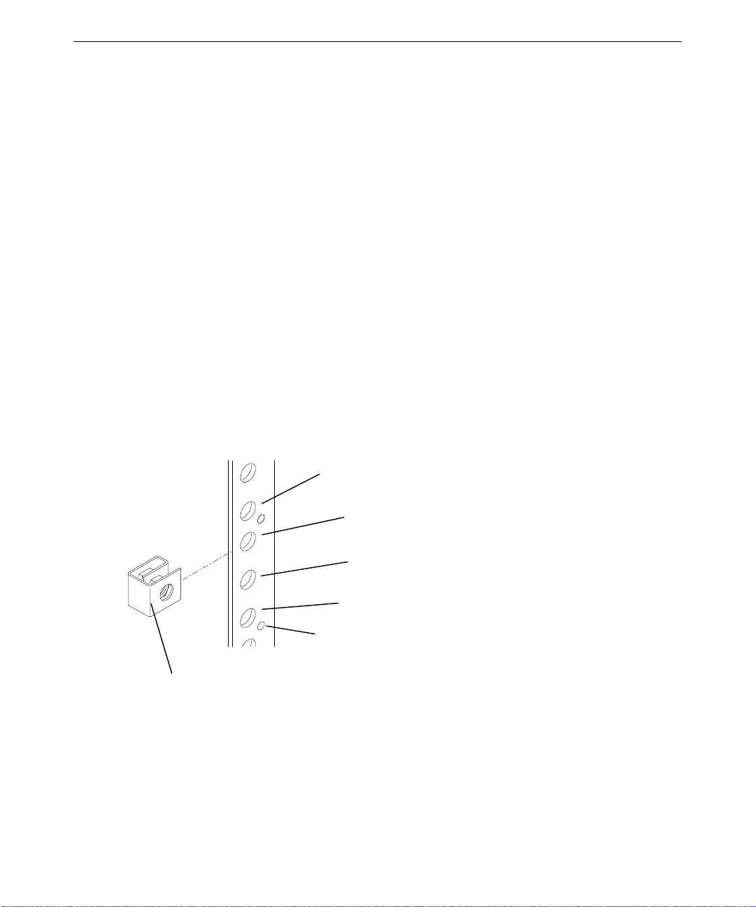
Understanding Rack-Mount Vertical Units
You can identify a vertical unit (U) mark as a round hole along the edge of the side rails. Note that
it is smaller than the mounting holes used to secure equipment in a rack. The 40 U rack
additionally uses a square hole to indicate every fourth vertical unit. You should determine the
vertical mounting space within a rack enclosure for each device you wish to install. For example,
an AC distribution box can require 1 U or 2 U of mounting space, while the InterServe 90 requires
six vertical units (6 U), or 10.5 inches, of mounting space.
♦ A vertical unit equals 1.75 inches and consists of three mounting holes.
♦ The mounting hole diameter is 7.1 mm (industry standard).
♦ Mounting holes are counted upward after locating the first mounting hole within the range of
vertical units required to install the equipment.
The following figure shows installing a tinnerman nut to mounting hole 3 of a vertical unit.
Tinnerman Nut
Mounting Hole 4
Mounting Hole 3
Mounting Hole 2
Mounting Hole 1
Vertical Unit Marker
Page 15

Installing a Rack-Mount Base Unit
CAUTION Two persons are required to perform the following procedures.
To install a rack-mount base unit:
1. Remove the system base unit and mounting rails from the carton and shipping materials. Use
a helper!
2. Install the handle brackets on the base unit, using the screws provided.
3. If the rail guides are already attached to the base unit, skip to step 4. If the rail guides are not
attached to the base unit, do the following:
− Remove the rail guides from the mounting rails. The rail guide is the innermost sliding
piece of the mounting rails, and has a flexible tab at one end.
− Attach the rail guides to the base unit using the flat-head screws provided, making sure
the tab on the rail guide is towards the back of the base unit.
4. Use the button-head screws and bolts provided to loosely secure the rail brackets to the rack
rails. See the following figure. The rail brackets have the rail teeth needed to secure the rack
rails to the back of the rack. Install the button-head screws and bolts loosely so you can adjust
the back rail teeth positions as needed in step 8.
5
Front Rail Teeth
Rail Bracket
Side Tab
Back Rail Teeth
Bolts
5. The rack-mount InterServe 90 requires 6 U (10.5 inches) of mounting space. Choose the six
vertical units you need and mark the sixth and seventh mounting holes starting at the b ottom of
the six vertical units. Use a tape measure if you prefer that method of measurement.
6. Use the flat-head screws and bar nuts to secure the front rail teeth to the front of the rack.
Page 16
6
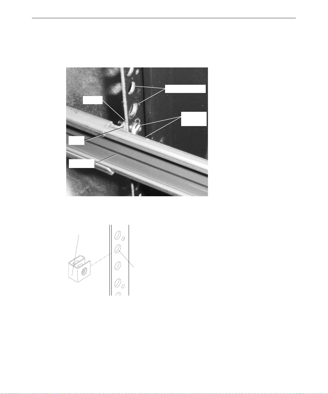
7. With the flat side of the bar nut facing the screws, loosely install two flat-head screws to the
bar nut, through the sixth and seventh mounting holes of the bottom 6 Us. Slide the front rail
teeth over the screws and tighten. Ensure the front rail teeth are between the bar nut and the
mounting holes. Refer to the following figure.
Mounting Holes
Bar Nut
Flat-Head
Screws
Teeth
Rack Rail
8. Slide tinnerman nuts over the third and thirteenth mounting holes starting from the bottom of
the 6 Us. The tinnerman nuts will be used when you secure the handle brackets on the front of
the base unit to the front of the rack. Refer to the following figure.
Tinnerman
Nut
Mounting
Hole
9. Use the button-head screws and bar nuts provided to secure the back rack rail teeth to the back
of the rack.
10. With the flat side of the bar nut facing the screws, loosely install two button-head screws to
the bar nut, through the fifth a nd sixth mounting holes of the bottom 6 Us. Slide the back rail
teeth over the screws and tighten. Ensure the back rail teeth are between the bar nut and the
mounting holes. Refer to the following figure.
Page 17
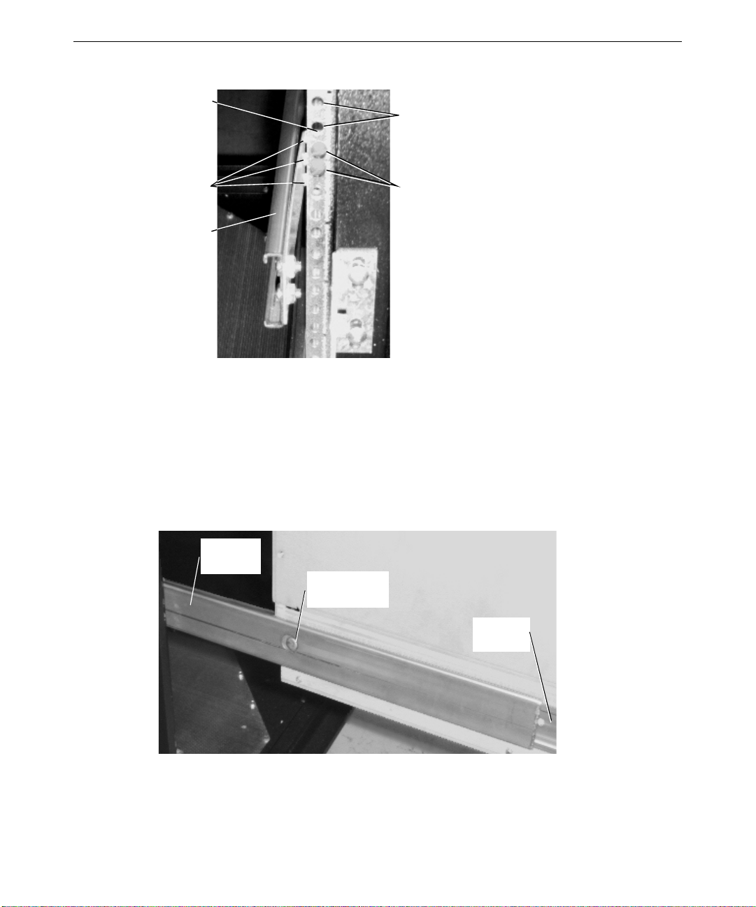
7
Bar Nut
Teeth
Rack Rail
Mounting
Holes
Button-Head
Screws
11. Tighten the screws on the rail brackets on each rack rail in the back of the rack.
12. Extend the rails from the rack until they lock.
13. With a person on each side, lift the base unit and align the rack rails with the rail guides
mounted on the side of the base unit. Slide the base unit into the rack rails until you hear a
click. Refer to the following figure.
14. Press the locked rail tabs and slide the base unit completely back into the rack. After the base
unit slides back a few inches, the base unit and rails slide together as a unit into the rack.
Refer to the following figure.
Rack Rail
(Each Side)
Locked Rail Tab
(Each Side)
R a il Guide
(Each Side)
15. Install the b l ack screws through the handle brackets and the tinnerman nuts you installed
previously to secure the base unit to the rack.
Page 18
8
Connecting the Cables
All cable ports on the base unit and other Intergraph Computer Systems equipment are keyed or
molded and labeled to ensure proper cable attachment. If a cable is not attaching easily, ensure
that you are aligning the cable connector correctly with the port.
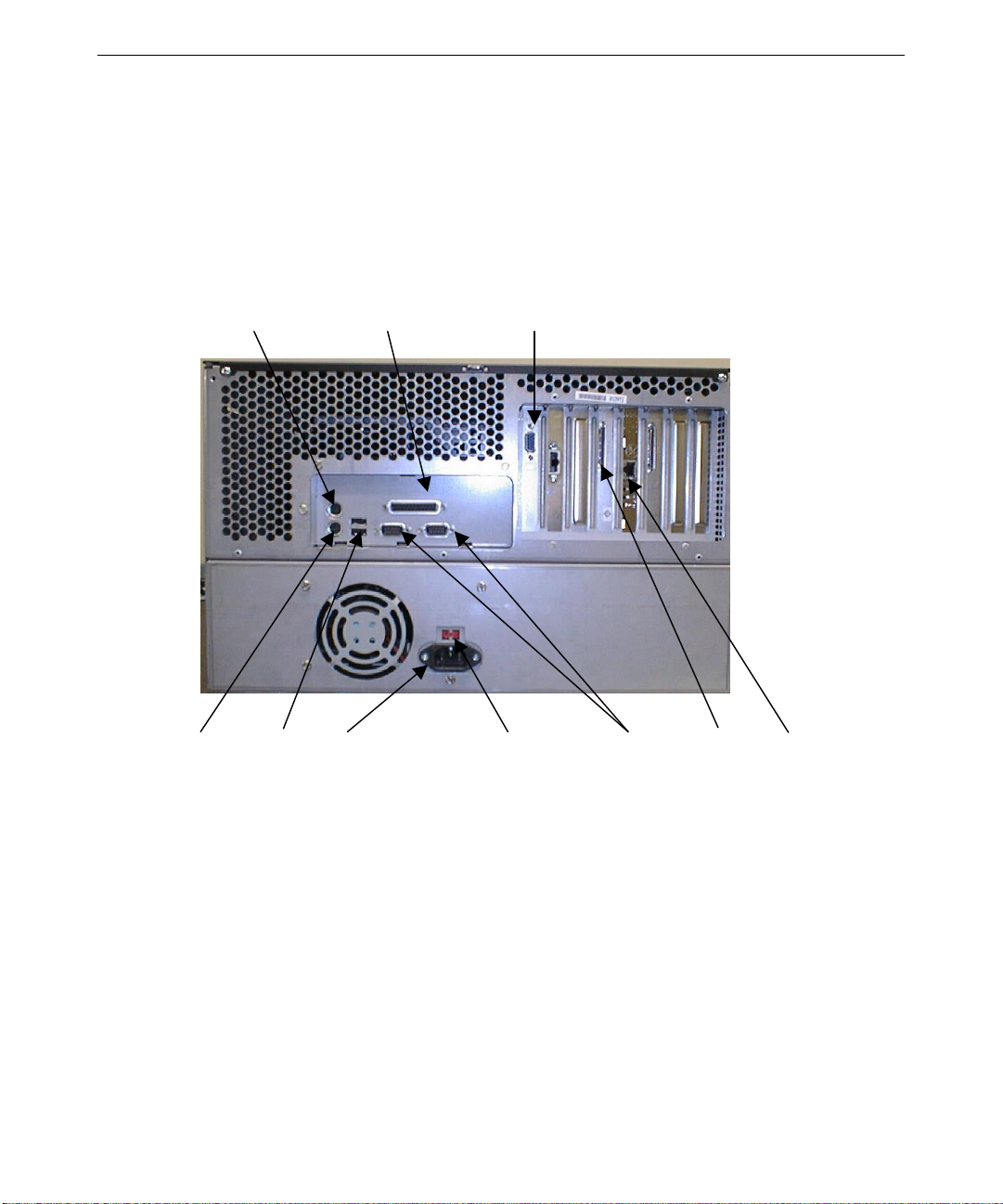
The following figure shows the ports and connections on the back of the base unit. Refer to this
picture as needed when following the cable connection procedure.
Mouse Parallel Monitor
Keyboard USB AC Power Voltage Selection Serial SCSI Network
WARNING If you do not use cables from Intergraph Computer Systems, you must use
shielded cables to prevent excessive electromagnetic interference (EMI).
Intergraph Computer System cables are designed to reduce the amount of EMI
produced by the system.
NOTE While Intergraph Computer Systems recommends disconnecting the cables from the
base unit before extending the base unit from the rack, you can still extend the base
unit without disconnecting the cables. Be sure there is enough cable to allow the
base unit to fully extend from the rack. Use caution not to pinch the cables while
extending or retracting the base unit.
NOTE For information about RAID ports, refer to the documentation delivered with the
controller. For information about the Video Out port, refer to the documentation
delivered with the video card.
Page 19

The base unit ports are labeled for easy reference. Refer to the following table as needed when
connecting cables to the base unit.
9
Connect the cable from this
To this port Connector
Mouse or mouse cable from concentrator Mouse port
Keyboard (optional) or keyboard cable
Keyboard port
from concentrator
Universal Serial Bus device
Modem, printer, or other serial device
Printer or other parallel device
Network
1
Universal Serial Bus port
Serial (COM) ports 1 and 2
2
Parallel (LPT) port
Ethernet port on the network
adapter card (optional)
Monitor (optional) or monitor cable from
concentrator
Video Out port on the graphics
adapter card
To connect the cables:
1. If you are using a monitor with the system, connect the video cable from the monitor (or the
equivalent cable from a concentrator) to the video out port on the video card in the expansion
slots.
2. Connect the cables for the mouse and keyboard (or the equivalent cables from a concentrator)
to their ports on the I/O panel.
3. Connect other cables to other ports as needed for such devices as printers (parallel port) and
modems or UPS communications (serial ports).
4. Connect any external SCSI devices to the appropriate port on the SCSI adapter card in the
expansion slots. See “Connecting an External SCSI Device” later in this chapter for more
information.
5. Connect cables to ports on other installed expansion cards, such as a RAID controller or a
Fibre Channel host bus adapter, as needed. See “Installed Expansion Cards” later in this
chapter and expansion card documentation for more information.
6. Make sure the voltage selection switch on the back of the base unit is set to the proper line
voltage for your location. If your location uses 115 volts, make sure the number 115 is visible
on the switch. If your location uses 230 volts, make sure the number 230 is visible on the
switch.
WARNING If you do not set the voltage selection switch correctly, serious equipment
damage may result when you turn on power to the system.
Page 20

10
7. Connect the system power cord to the AC receptacle on the base unit.
8. If using an AC distribution box or UPS, connect its power cord to a grounded, three-prong AC
power outlet.
CAUTION Ensure the circuit breaker on the AC distribution box is set to Off before connecting
the power cord.
NOTE The UPS starts automatically when its power cord is connected to the power outlet.
Refer to the UPS documentation for more details.
9. Connect the power cords from the monitor, system, and any external optional peripherals to
receptacles on a grounded, three-prong AC wall outlet, an AC distribution box, or an
uninterruptible power supply (UPS).
10. If you have any disk drives to install in the disk drive bay, refer to “Installing Disk Drives in
the Disk Drive Bay” later in this chapter.
Installed Expansion Cards
Expansion cards are installed in the Accelerated Graphics Port (AGP), Peripheral Component
Interconnect (PCI), and Industry Standard Architecture (ISA) expansion slots in the base unit. The
layout of expansion slots and the typical location of some installed expansion cards are as follows:
Slot
Left AGP Graphics adapter
Right ISA
For information on installing additional expansion cards, see the System Reference and the
documentation delivered with the expansion cards.
Type Expansion Card
PCI Open
PCI Symbios dual-channel LVDS SCSI adapter
PCI QLogic Fibre Channel host bus adapter (optional)
PCI Mylex RAID controller (optional)
PCI Network adapter
Page 21
Installing Disk Drives in the Disk Drive Bay
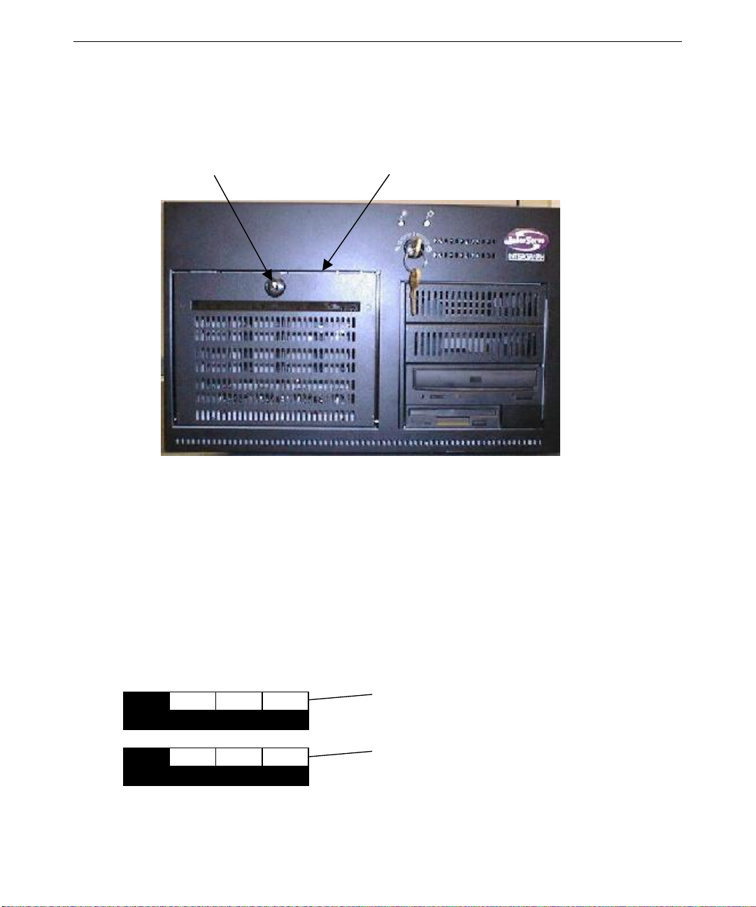
The following figure shows the disk drive bay door and door lock on the front of the system.
Door Lock Disk Drive Section Door
11
The disk drive bay may contain up to four JBOD (for “just a bunch of disks”) or RAID SCA
SCSI disk drives. JBOD disks are controlled by a Symbios dual-channel Low Voltage Differential
Signaling (LVDS) SCSI adap ter. If your system is configured for RAID, a single-channel Mylex
RAID controller provides RAID capabilities such as disk striping, mirroring, and redundancy.
Each disk drive installed in the disk drive bay has a label affixed to the front. The left side of the
disk drive label identifies the disk drive size (in GB). The label has blank spaces for the numbers
to indicate the adapter (ADP), the channel (CH), and the identification number (ID). Standard disk
drives include values for the adapter, channel, and identification number filled in. Additional disk
drives have a blank label which you must complete after installation.
NOTE A labeling sheet is included in the system parts box.
x GB
x GB
ADP
ADP
100
CH ID
CH ID
Filled-in Label
Blank Label
Page 22
12
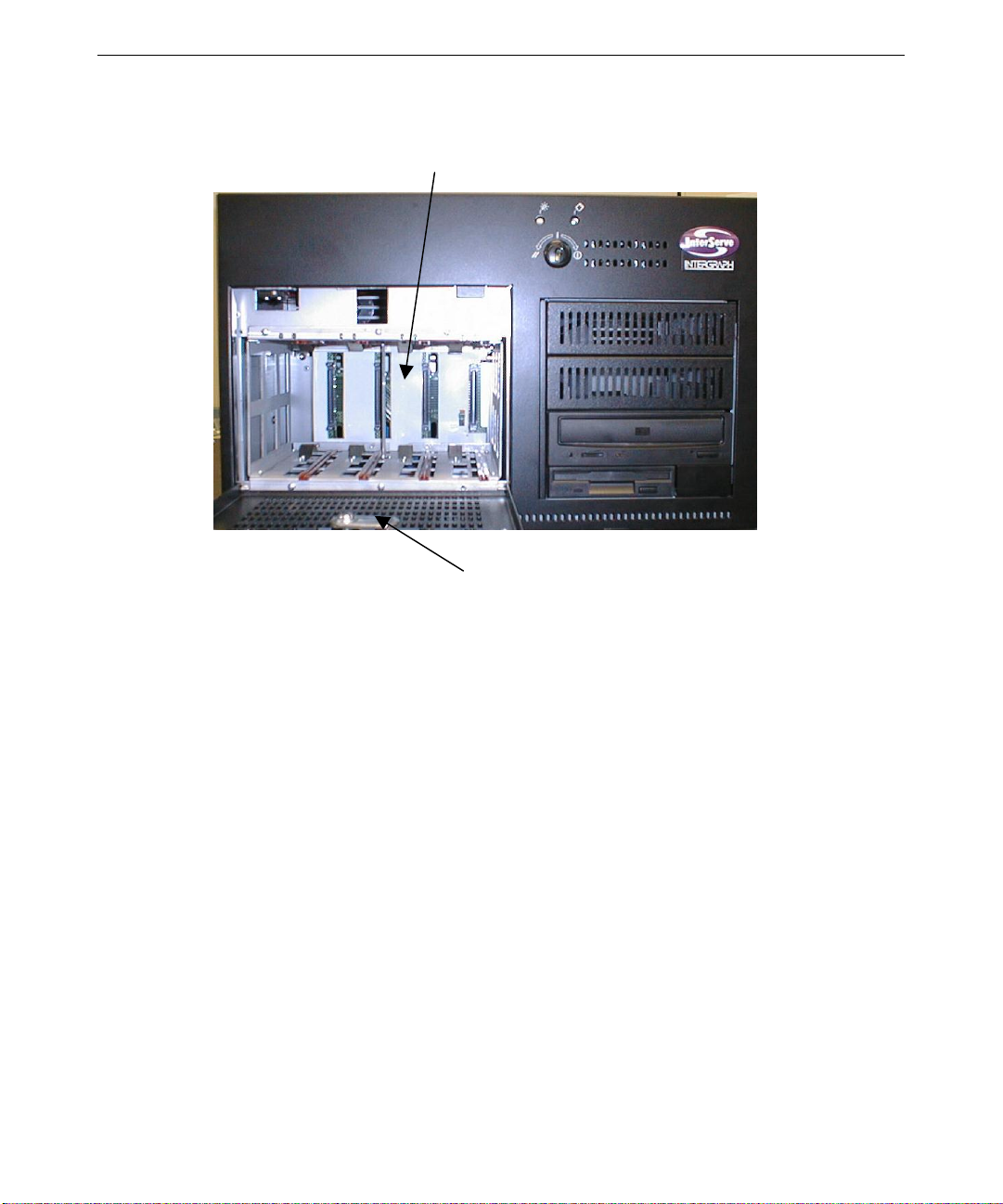
The following figure shows the system with the disk drive bay door open.
Disk Drive Slots (4)
Disk Drive Section Door (Open)
To install JBOD or RAID disk drives:
1. Open the disk drive bay door on the front of the base unit. The key is in the parts box.
2. Remove the disk drive(s) fr om the disk drive carton and place them on an antistatic surface.
Carefully open the antistatic bag(s) and remove the disk drive(s). Note the ID number on the
drive(s).
3. Extend the latching clips on Drive 0 and align the rails on the side of the drive with the slot
guides in the rightmost slot. The me tal casing of the drive faces to the left. If you install the
drive reversed, it will not connect to the system. In a deskside configuration, the disk drive
section will be rotated 90 degrees, and the metal casing will face toward the ground.
4. With your thumb, push the drive at the center between the latching clips until it slides all the
way into the slot and firmly engages the connector.
5. Close the latching clips to lock the drive in the slot.
6. Repeat steps 3 through 6 to install each remaining disk drive. Fill each slot, moving to the left
adjacent slot as you install each drive. Do not leave empty slots between drives.
Page 23
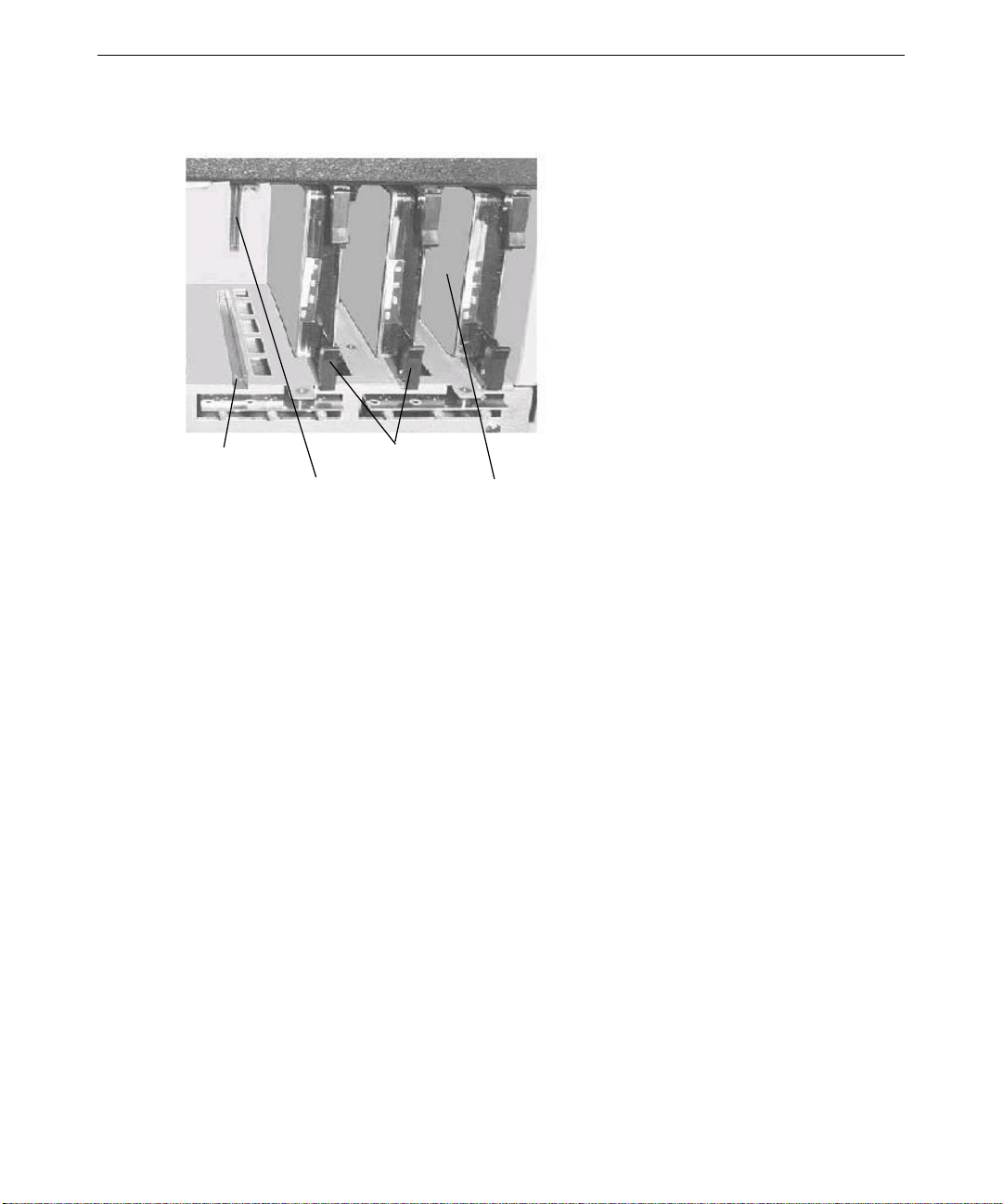
The following figure shows three disk drives installed in the disk drive bay.
13
Drive Rail
Drive Connector
Latching Clips
Drive 0
Connecting an External SCSI Device
The optional SCSI adapter card is designed to support Ultra Wide SCSI devices. Ultra Wide SCSI
provides a maximum data transfer rate of 80 MB per second. If you connect a non-Ultra Wide
SCSI device to the adapter, data transfer rates are limited to the speed of that device.
CAUTION Using a non-compliant SCSI-1 device with your system may cause your system to
stop working or lead to other unpredictable results.
You can connect up to seven external single-ended SCSI devices to the SCSI adapter. However,
the number of drives and length of the cables used to connect the drives is a factor when using
SCSI-1, Fast SCSI (SCSI-2), Ultra SCSI, and Wide Ultra SCSI drives. Fast SCSI, Ultr a SCSI,
Wide Ultra SCSI, and LVDS impose shorter cable restrictions than SCSI-1.
NOTE Make sure the last device on a chain of external SCSI devices has an active SCSI
terminator connected to the open SCSI port. All other external SCSI devices must
have SCSI termination disabled or removed.
See the System Reference and the SCSI adapter documentation for more detailed information on
the SCSI adapter and connecting SCSI devices to it.
Page 24

14
Checking the System
Before starting the system, review the following items.
For a rack-mount unit:
♦ All hardware is properly and securely installed in the rack.
♦ There is enough slack cable to allow the base unit to extend from the rack.
♦ The cables that run along the sides or top of the rack have clips or ties to secure them in place.
For deskside and rack-mount units:
♦ The cables are properly connected to the base unit.
♦ All JBOD or RAID disk drives are installed in the proper slots in the disk drive bay and are
labeled appropriately.
♦ The voltage selection switch on the back of the base unit is set to the proper voltage for your
location (115 volts or 230 volts).
♦ The power cord from the AC distribution box or UPS is connected to the correct power outlet.
♦ The base unit is retracted into the rack.
WARNING Once you install equipment into the rack, do not move the rack, or equipment
damage may result. If you must move the rack, first remove all equipment,
move the rack to its new location, and then reinstall the equipment.
Starting the System
WARNING If you start the system, and then turn it off before completing the instructions in
Chapter 2, “Setting Up the Software,” you will have to reinstall the operating
system and associated system software. See “What’s Next” for more
information.
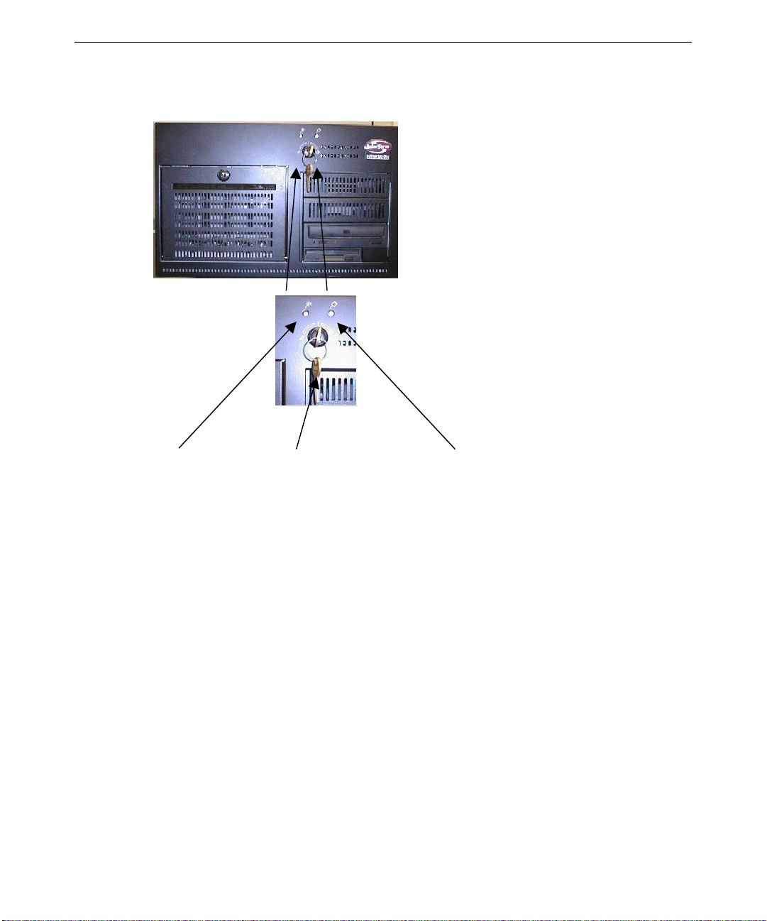
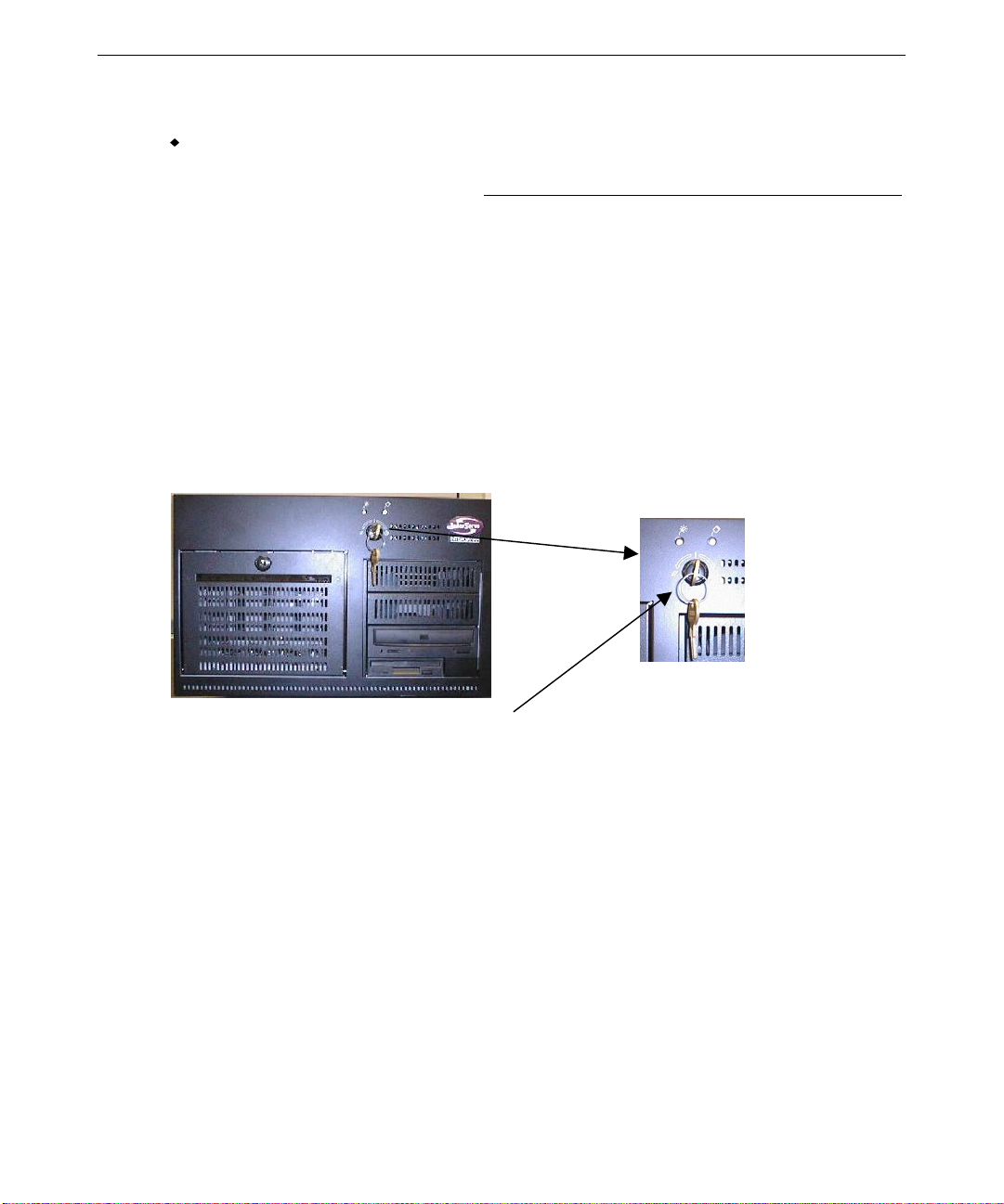
To start the system, turn the Power keyswitch shown in the following figure. If you have an AC
distribution box or a UPS connected to the system, make sure its power switch is turned on before
you start the system.
See Chapter 2, “Setting Up the Software,” before using the Power keyswitch to start the system for
the first time.
Page 25
15
Status LED Power Keyswitch Disk Activity Indicator LED
What’s Next?
You can do any of the following to prepare your system for use:
♦ If you want to get going with Intergraph’s default setup, go to Chapter 2, “Setting Up the
Software,” to start the system and go through Windows NT Setup. If you start the system,
and then turn it off before completing the instructions in Chapter 2, you will have to
reinstall the operating system and associated system software.
♦ Intergraph Computer Systems installs the operating system through P hase 1 of the Windows
NT Setup process. If you want to reload the operating system and system software instead of
completing Phase 2 of Setup, see Chapter 7, “Reinstalling System Software.”
♦ For RAID systems, the default RAID setup is disk drives striped to RAID level 5, with a
write-through write policy and a cached I/O policy. The default setup is described in more
detail in Chapter 3, “Configuring the System.”
Page 26

16
Page 27

2 Setting Up the Software
Follow the instructions in this chapter to set up the operating system and associated system
software for your InterServe 90.
Preparing for System Software Setup.............................................................................................18
Starting Operating System Setup.................................................................................................... 20
Finishing System Software Setup ................................................................................................... 21
Creating an Emergency Repair Disk ................................................................................ 21
Creating System Software Backup Diskettes ................................................................... 22
Creating a QFE Update Software Diskette..................................................................................... 22
What’s Next? .................................................................................................................................. 22
17
Page 28

18
Preparing for System Software Setup
Your system’s primary system disk drive and any additional disk drives were formatted and
partitioned before shipment. In Explorer or My Computer, you can right-click a disk drive and
click Properties to display the drive’s partition size and file system format. To view partition and
format information for all disk drives, you can use Disk Administrator. See the operating system
documentation and Help for more information on these tools.
The operating system and associated system software is pre-installed on the system’s primary hard
disk drive. Intergraph Computer Systems installed the following system software:
♦ Driver software for the installed RAID or SCSI adapter(s)
♦ Driver software for the installed video display adapter and the mouse
♦ Driver software for optional expansion cards installed at the factory, such as a RAID
controller, a Fibre Channel host bus adapter, and a network adapter.
♦ Quick-Fix Engineering (QFE) software (fixes for operating system problems or limitations), if
needed
♦ Windows NT Service Pack software
♦ InterSite software
Intergraph Computer Systems installs the operating system through P hase I of the operating system
Setup process. You must follow the operating system Setup process to prepare Microsoft Windows
NT Server fo r use. Before you go through Setup, have the following available:
♦ Microsoft’s Start Here document
♦ Documentation for the system’s video display adapter and network adapter
♦ Documentation for any expansion cards purchased from Intergraph Computer Systems
♦ The Late-Breaking News document delivered with the system
Get and record the following information:
u
Your name, and the name of your
company or organization:
u
For a system running Windows NT,
the CD key from the Windows NT
CD case, the Product ID Number
from Start Here, or the registration
card:
Page 29

If the system is connected to a network, obtain and record the following information for your
system from your network administrator:
u
Computer name:
u
Wo rkgroup name (if the system will
be part of a workgroup):
u
Domain name (if the system will be
part of a Windows NT domain):
u
Security role for your system in the
Windows NT domain -- primary
domain controller, backup domain
controller, or domain server:
u
If your system will be acting as a
backup domain controller or domain
server, username and password of
an authorized domain administrator
account:
NOTE Determine the security role for your server before beginning system configuration.
You cannot change a server to a domain controller without reinstalling Windows NT
Server. A domain controller maintains security policy and performs user
authentication for a domain. Servers may be part of a domain, although they do not
have to participate in a domain. See the operating system documentation for a
detailed explanation of the differences between domain controllers and servers.
19
If the system is connected to a network that uses the Transmission Control Protocol/Internet
Protocol (TCP/IP ), get and record the following TCP/IP information for your system from your
network administrator:
u
Internet Protocol (IP) address:
u
IP subnet mask:
u
IP domain name for your ne twork:
u
IP address for your network’s
default gateway:
u
IP addresses for your network’s
Domain Name System (DNS)
servers, if any:
Page 30
20
u
IP addresses for your network’s
Windows Internet Name Service
(WINS) servers, if any:
The Windows NT delivery media contain software and drivers for both Reduced Instruction Set
Computing (RISC)- and Intel-based systems. When installing Windows NT distribution files,
make sure you install them from the \
I386 directory (the Intel software directory) on the delivery
media.
Starting Operating System Setup
To start the system, turn the Power keyswitch to the right (clockwise). The Power keyswitch is
shown in the following figure. If you have an AC distribution box connected to the system, make
sure its power switch is turned on before you start the system.
Power Keyswitch
The first time you start the system, it boots to a Microsoft End User License Agreement (EULA)
screen. After reading and accepting the terms of the agreement, follow the instructions to continue
operating system Setup. Take the default settings provided by Setup, except as noted in the
following text. You can set up a user account and join a workgroup or domain after you configure
the video display and networking.
NOTE Before starting the system for the first time, you may want to learn more about
system power, startup, and shutdown. See Chapter 4, “Operating Notes,” for this
information.
To start the computer and set up the operating system software:
1. Turn on the monitor by pressing its power switch.
2. Turn the Power keyswitch on the base unit. The system starts and the EULA screen displays.
Page 31

21
3. Read the terms of the EULA and then follow the instructions displayed on-screen to complete
the Setup process. A Welcome screen displays, then a prompt for user and organization, and
then a prompt for the product ID. Accept the default settings provided by Setup.
− When setting up the operating system software, remember the following:
− When prompted to create an Emergency Repair Disk, do so.
− If you do not set up a user account during Setup, press ENTER or select OK at the logon
dialog to log on to the operating system.
− You can use the C:\i386 directory when prompted for the location of Windows NT Setup
files. If you delete the i386 directory from the system’s hard disk, you must have access to
a Windows NT CD-ROM to use Windows NT Setup files.
After you configure networking, you can join a workgroup or domain. You cannot set up a user
account until after you have completed setup and rebooted the system. See Windows NT Help for
details on setting up a user account and joining a workgroup or domain.
For more information on Setup, and on using the interface features of the operating system, refer to
the operating system documentation and Help.
Finishing System Software Setup
After operating system Setup completes, a Press to finish setup icon displays on the operating
system desktop. Double-click this icon, or go to Programs/InterSite/Welcome on the operating
system Start menu, to display InterSite Welcome.
InterSite Welcome helps you create a repair disk for the operating system, and create backup
diskettes of device driver software and other system software products. You can use InterSite
Welcome to get the latest driver and other system software from the World Wide Web, and to
learn about Intergraph Computer Systems customer support.
You should take advantage of the tools provided by InterSite Welcome to ensure that your system
is fully ready for use. See InterSite Welcome for more information. Also see the following
sections for information on creating a repair disk and creating backup diskettes.
Creating an Emergency Repair Disk
If you did not create an Emergency Repair Disk during Setup, use the tools provided by InterSite
Welcome to do so. See the operating system documentation and Help for information on creating
an Emergency Repair Disk. You should also update an Emergency Repair Disk after you finish
configuring the system.
Page 32

22
In the event of corrupted disk drives, the files on the Emergency Repair Disk restore the contents
of the operating system registry at the time the operating system was installed, along with the
standard operating system drivers.
Creating System Software Backup Diskettes
Although backup media for device drivers and system software products are delivered with the
system, you should periodically run InterSite Version Manager to ensure you have the latest
drivers and make backup diskettes for updated software. To make backup diskettes, use InterSite
Version Manager (available through InterSite W elcome or InterSite Manager ), or by selecting
Start/Programs/InterSite/Version Manager.
Version Manager lets you create backup diskettes containing device driver software and system
software products that were installed on the system before shipment, and which are not available
on the operating system CD-ROM. You may need these backup diskettes later -- for example, if
you have to reinstall a device driver or the operating system.
NOTE InterServe products are delivered with backup media of all drivers and other system
software products.
NOTE You may not have to create backup diskettes for all system software. If Version
Manager does not list drivers or other system software products, then they are
available on the operating system software CD, or on backup media delivered with
the system.
See Version Manager Help for information on creating system software backup diskettes. Visit the
Intergraph Computer Systems site on the World Wide Web and vendor bulletin boards for new and
Creating a QFE Update Software Diskette
If the system requires Quick-Fix Engineering (QFE) update software, it is included in the system
software available for backup diskette creation. QFE update software contains fixes for operating
system problems or limitations, and is only shipped with the system if it is needed.
If QFE update software is shipped with the system, you should create a QFE backup diskette for
use if you have to reinstall the operating system. See the README.TXT file on the QFE diskette
for information on the applicability and installation of QFE update software on your system.
What’s Next?
See Chapter 3, “Configuring the System,” to configure the system for use. See Chapter 4,
“Operating Notes,” for related details.
Page 33

23
3 Configuring the System
Follow the instructions in this chapter to configure your InterServe 90 for use. This chapter covers
items required for basic operation.
Configuring the Video Display....................................................................................................... 26
Changing the Default Video Display Driver .................................................................... 26
Correcting Video Display Problems................................................................................. 26
Configuring RAID Disk Drives...................................................................................................... 27
Basic RAID Configur ation ............................................................................................... 27
Resetting to the Default RAID Configuration.................................................................. 30
Configuring Non-RAID Disk Drives....................................................................................... 31
Installing and Configuring Intersite Server Monitor....................................................................... 32
Changing Drive Letters ................................................................................................................... 33
Changing Virtual Memory Settings................................................................................................33
Configuring the Symbios SCSI Adapter......................................................................................... 34
Using the SCSI Configuration Utility
Creating an Emergency Repair Disk...............................................................................................36
Getting Operating System Updates………………………………………………………...…..36
………………………..……………………………....………....35
Page 34

24
Configuring the Video Display
The first time you start the system, it uses the installed video d i splay adapter running at 1024 x 768
to run the video display. For the system to use the installed video adapter at other display
resolutions, you must configure the video display driver. Refer to the documentation delivered
with the video display adapter for information about available settings. For information on using
the Display Properties dialog, refer to the operating system documentation and Help.
Changing the Default Video Display Driver
After configuring the video display and restarting the system, you should configure the system to
use the Intergraph video display driver by default.
To change the default video display driver:
1. Open System in the Windows NT Control Panel. The System dialog displays.
2. Under Operating System, select the Startup list; then select the appropriate non-VGA
Windows NT Server option from the displayed list.
3. Select OK.
Correcting Video Display Problems
If the system’s video display is black, not synchronized, or distorted after you restart the system,
you may have a video configuration problem.
Do not press
correct the problem by using the Last Known Good option to return the system to the last known
good configuration recorded by Windows NT.
To use the Last Known Good option:
1. Power down and restart the system.
2. Press the space bar at the following prompt:
Press space bar NOW to invoke the Last Known Good Menu
If using the Last Known Good option fails to correct the video display problems, you can obtain a
functional video resolution by restarting the system in VGA mode.
CTRL+ALT+DEL to log on to the Windows NT operating system. Instead, try to
Page 35

To restart the system in VGA mode:
1. Power down and restart the system.
2. At the boot screen, select the VGA mode option.
After logging on to Wind ows NT in VGA mode, check for the following common configuration
problems and solutions:
♦ A multi-sync monitor is selected, but a graphics display device with different video timings
(such as an Intergraph InterVue monitor) is connected to the system. Select the appropriate
monitor type as described previously.
♦ The monitor selection is inappropriate for the monitor connected to the system. Select a new
monitor.
♦ There is not enough vide o display memory to support the selected graphics resolution and
color depth. Install and reconfigure the video disp lay to use a lower resolution and color
depth.
Restart the system and, when the boot screen displays, select the appropriate non-VGA Windows
NT Server to use the reconfigured video display driver. If problems persist, contact the Intergraph
Customer Response Center at 1-800-633-7248 for help.
25
Configuring RAID Disk Drives
NOTE This section only applies to systems that use RAID disk drives.
This section describes the RAID hardware used in the system, explains the standard RAID disk
configuration, and provides guidelines to configure additional RAID drives. The standard RAID
hardware is pre-configured by Intergraph Computer Systems before shipment.
CAUTION If you change the factory-set configuration of RAID disk drives, you must reinstall the
system software. See Chapter 7 for instructions.
Basic RAID Configuration
The InterServe 90 system contains three main RAID hardware components:
♦ A disk drive section
♦ Up to four RAID disk drives
♦ One RAID controller (also known as an adapter)
The disk drive section has four slots for installing RAID disk drives. The slots are numbered from
0 to 3, starting with the rightmost slot. Each slot also has a corresponding SCSI ID number, which
Page 36

26
is determined by the hardware configuration of the RAID section and the installed RAID
controller. The SCSI ID numbers are 1, 2, 4, 5.
NOTE For technical information about the disk section, refer to the
technical information on the RAID controller, refer to the Mylex RAID controller
documentation.
04 GB
ADP
0
CH
1
ID
System Reference
. For
The spaces above ADP, CH, and ID are filled in before shipment to identify the drives.
♦ ADP means the RAID controller (adapter) number connected to the RAID section.
♦ CH means the RAID SCSI bus channel of the adapter (each adapter has two channels).
♦ ID means the identification number of the drive in the slot.
NOTE When the standard disk drives are configured by Intergraph Computer Systems (as
described below), they assume the ID number of the internal disk section slot.
The disk drive section is connected to the RAID controller by internal SCSI cables.
Three or four RAID drives may be installed and configured with the Mylex RAID controller
software at the factory. These RAID drives are configured to appear as one logical drive in
Window NT Disk Administrator. The logical drive has a 2 GB NTFS system disk partition; the
rest of the logical drive is formatted as one NTFS partition, for a total of two partitions. A RAID
disk drive installed at the factory assumes the ID number of the disk drive section slot in which it is
installed.
The default configuration for factory-installed RAID disk drives is as follows:
♦ RAID level 5
♦ Write-through write policy
♦ Cached I/O policy
♦ Two disk drives spin up every 6 seconds
♦ Ultra SCSI enable
The Mylex RAID controller BIOS and Mylex RAID configuration utility let you view and change
the way in which the RAID controller treats the RAID drives. For example, you can make each
drive a separate partition, instead of three drives being one partitio n.
NOTE For detailed information about using the Mylex RAID controller BIOS or Mylex RAID
configuration utility, refer to the Mylex RAID controller documentation.
Page 37

The following figur e shows the correlation between the disk drives (labeled), their slot location
(shaded areas), and how they are identified in Mylex BIOS and the Mylex utility.
NOTE SCSI ID 3 is the SAF-TE card. This corresponds to Mylex ID 3. The following figure
displays SCSI IDs and Mylex IDs for the disk drives, but Mylex ID 3 is still shown for
clarity since it appears in the Mylex BIOS and Mylex utility display.
27
ADP 0
Slot 0
Slot 1
Slot 2
Slot 4
Slot 3
SCSI ID 0
SCSI ID 1
SCSI ID 2
SCSI ID 4
0CH0ID0
ADP
0CH0ID1
ADP
0CH0ID2
ADP
0CH0ID4
ADP
Disk Label
7JW&KDQQHO1XPEHU
,'
Mylex ID
The non-volatile memory and flash EEPROM on the RAID controller board stores the
configuration data. When you restart the system, the RAID controller uses this information to
define the RAID configuration to the operating system.
Throughout the Mylex RAID configuration utility, a banner at the top of the display shows the
title, version number, date, controller name, slot number, and firmware version. The bottom of the
display indicates the actions you can take for each menu option. Additionally, information bo xes
describe possible actions no t allowed. Warning boxes display when the next action could destroy
data on the drives, erase configurations, or has other serious system consequences.
The following table de fines the terms you will see while running the Mylex RAID configuration
utility to configure the drives.
RDY Disk drive ready for configuration
CDR CD-ROM drive
TAP Tape drive
UNF Unformatted drive
PAK Configured packs
DRVS Number of drives in a pack
SIZE Size of the packs (in megabytes)
ONL Drive online (part of pack)
DED Failed drive
RBD Rebuilding
WRO Rebuilding (write only)
FMT Formatting
SBY Standby drive
Page 38

28
Resetting to the Default RAID Configuration
If you modify the RAID configuration, and want to return to the default settings, use the following
procedure. For details about using the Mylex RAID configuration utility, refer to the Mylex RAID
controller documentation.
To reset the default RAID configuration:
1. Restart the system.
2. When prompted, press
ALT+R to enter the Mylex RAID configuration utility. The Main Menu
displays. The Help box (below the Main Menu) briefly describes the operations you can
perform with the highlighted option. Use the cursor keys to select the options in the Main
Menu and press
ENTER to select the highlighted option.
3. Move the cursor down and select New Configuration to set up one 8 GB array to RAID level
5, and write through write policy.
4. Restart the system.
Configuring Non-RAID Disk Drives
NOTE This section only applies to systems that use non-RAID disk drives.
The InterServe 90 Rack Mount system contains three main non-RAID hardware components:
♦ A disk drive section
♦ Up to four non-RAI D disk drives
♦ One SCSI controller (also known as an adapter)
The standard non-RAID hardware is pre-configured by Intergraph Computer Systems before
shipment. The standard configuration includes one non-RAID disk drive (with pre-installed
operating system and system software) for the disk drive section and one SCSI controller. The
disk drive is installed in slot 0 of the disk drive section, and has the following label to identify the
drive:
04 GB
ADP
0
CH
0
ID
The spaces above ADP, CH, and ID are filled in before shipment to identify the drive.
♦ ADP means the SCSI controller (adapter) number connected to the SCSI section.
♦ CH means the SCSI bus channel of the adapter (each adapter has two channels).
♦ ID means the identification number of the drive in the slot.
Page 39

29
NOTE When the standard disk drive is configured by Intergraph Computer Systems (as
described below), it assumes the ID number of the internal disk section slot.
The disk drive section is connected to the SCSI controller by internal SCSI cables.
Intergraph Computer Systems configures one non-RAID drive before shipment. The non-RAID
drive 0 has a 2 GB NTFS system disk partition; the rest of drive 0 is formatted as another NTFS
partition for a total of two partitions. If you order additional non-RAID disk drives from
Intergraph Computer Systems, each add itional disk drive is formatted as one NTFS partition.
CAUTION If you change the factory-set configuration of non-RAID disk drives, you must reinstall
the system software. See Chapter 7 for instructions.
NOTE For technical information about the disk drive section, refer to the
For technical information on the SCSI controller, refer to the documentation delivered
with the SCSI controller.
System Reference
Installing and Configuring InterSite Server Monitor
If you ordered the InterSite Server Monitor option for server monitoring capability, your
InterServe 90has an installed InterSite Server Monitor (ISM) card (also called the Emergency
Monitor Card 2, or EMC2). For instructions to install and configure the ISM software, and for
information on using the ISM with your server, refer to the InterSite Server Monitor
documentation included with your system and the Late Breaking News document, if one is
delivered with your system.
See Chapter 5, “Co nfiguring the BIOS,” for mor e information on using BIOS Setup .
Changing Drive Letters
If you have more than one hard disk drive or CD-ROM drive, you may need to reassign system
drive letters.
To change drive letters:
1. Exit all applications currently running on your system.
.
2. From the Start menu, click Programs, Administrative Tools, and then Disk Administrator.
3. Select a hard disk drive or CD-ROM drive.
4. From the Tools menu, click Assign Drive Letter.
NOTE If you select the current drive or an otherwise locked drive, you must restart the
system to complete the drive letter reassignment.
Page 40

30
5. Select a new drive letter to assign to the drive from the list. Click OK, and then click Yes to
continue.
6. If necessary, click OK, and then click Yes.
7. Repeat steps 2 through 6 for each drive letter assignment that you want to change.
8. Click Partition, then click Exit. If necessary, restart the system to complete the drive letter
reassignments.
Changing Virtual Memory Settings
If you have more than one hard disk drive, you may need to change size and location of your
virtual memory page file. See Windows NT Help for more information.
Consider the following before changing page file settings:
♦ The size of the page file. If your system is equipped with a large amount of RAM, Setup
might create a page file that is unnecessarily large.
♦ Drive letter reassignments. If you reassigned your drive letters, you may find it necessary to
adjust your page file se ttings.
To change the size and location of the virtual memory page file:
1. From Start, click Settings, and then click Control Panel.
2. Double-click the System icon.
3. Click the Performance tab and then click Change.
4. Click a drive letter in the list, and then type new values in the Initial Size and Maximum Size
text boxes.
5. Click Set.
6. Repeat steps 4 and 5 for any additional drives in the list.
7. Click Close, then click OK. An alert box displays.
8. Do one of the following:
− Click Yes to restart the system with the new settings.
− Click No to continue with other tasks and use the new settings the next time you restart
the system.
Page 41

Configuring the Symbios SCSI Adapter
If your InterServe 90 system is equipped with an optional Symbios SCSI adapter, you may need to
use the SCSI Configuration Utility to configure the operation of SCSI peripherals connected to the
adapter. You can find the SCSI Configuration Utility (
delivered with the system.
The SCSI Configuration Utility allows you to configure the SCSI adapter, perform a low-level
format on a SCSI hard disk drive and verify media.
Change the SCSI adapter parameters on a per-device basis under the following conditions:
♦ If you are advised to do so by Intergraph Computer Systems technical support or instructed to
do so by the vendor documentation supplied with the SCSI device.
♦ If the SCSI device does not negotiate properly with the controller. This is common on older
drives.
♦ If you exceed the total cable length for connecting SCSI devices to the system, as specified in
the section, “Connecting an External SCSI Device,” in Chapter 1.
♦ If you connect non-Ultra or non-Wide Ultra SCSI external devices to the system.
PCI_CFG.EXE) on the SYSUTIL diskette
31
To run the SCSI Configuration Utility:
1. Insert the
SYSUTIL diskette in the system’s floppy disk drive.
2. Shut down and restart the system.
3. When the Startup Menu displays, select SCSI Configuration Utility and press
See SCSI Configuration Utility Help and the Symbios SCSI adapter documentation for instructions
on using the SCSI Configuration Utility.
Using the SCSI Configuration Utility
NOTE Change the synchronous data transfer rate or the data width parameters for an
individual device only. Do not change the parameters for the SCSI host adapter
itself. Changes to the SCSI host adapter affect all devices on its bus.
When using the SCSI Configuration Utility, remember the following keyboard tips:
♦ Press the up or down arrow keys to move about in the menus.
♦ Press
♦ Press
♦ Select Help to display a Help screen with instructions and details.
ENTER to confirm a menu selection.
ESC to cancel a selection.
ENTER.
Page 42

32
To change the synchronous data transfer rate:
1. Insert the SYSUTIL diskette in the system’s floppy disk drive.
2. From the Start menu, click Shut Down. The Shut Down Windows dialog box displays.
3. Click Restart and then click OK. The system restarts and the MS-DOS Startup Menu displays.
4. Select SCSI Configuration Utility and press
5. From the main menu, select the SCSI host adapter that you want to configure and press
ENTER.
ENTER.
One single-channel SYM8951 SCSI host adapter is listed.
6. From the Utilities menu, select Device Selections and press
ENTER.
7. From the Device Selections menu, select the SCSI device that you want to configure and press
ENTER.
NOTE Only eight SCSI devices are listed at a time. Select Device Selections 8-15 to list the
next eight SCSI devices.
NOTE If the device that you want to configure is not listed, exit the menu, repeat step 5 and
select the other host adapter. Then, continue with step 6.
8. Select Sync Rate (Megabytes/sec) and press ENTER.
9. Select the appropriate rate (Off, 10, 20, 40, or 80) and press
and then press
ENTER.
10. From the Device Selections menu, select Exit This Menu and press
11. From the Utilities menu, select Exit This Menu and press
ENTER, select Exit This Menu,
ENTER.
ENTER. The Save/Cancel menu
displays.
12. Select Save Changes and press
ENTER.
13. Remove the diskette from the system’s floppy disk drive, and then press any key to restart the
system.
Creating an Emergency Repair Disk
You should create an Emergency Repair Disk after you finish configuring the system. The files on
the Emergency Repair Disk can restore a damaged registry to its original contents (that is, at the
time Windows NT was installed), along with the standard Windows NT drivers.
Use the
Repair Disk. You can also use these utilities to update the Emergency Repair Disk any time you
change the system’s configuration. You should also make and keep a backup copy of the
Emergency Repair Disk.
Refer to the operating system documentation and Help for information on creating and using an
Emergency Repair Disk.
RDISK.EXE utility or InterSite Welcome (as described in Chapter 2) to create an Emergency
Page 43

Getting Operating System Updates
Microsoft Service Packs and Service Releases contain the latest improvements and system fixes for
Microsoft operating systems. Service Packs and Releases are created by Microsoft for post-release
support. You can get then from Microsoft’s World Wide Web and FTP sites free of charge.
CAUTION If Intergraph Computer Systems provides a Service Pack through the IBBS or with a
product, it has been certified against Intergraph Computer Systems hardware as
described in the announcement of its availability. If you obtain a Service Pack from
any other source, be aware that it may not be certified against your Intergraph
hardware.
33
Page 44

34
Page 45

4 Operating Notes
This chapter contains basic information on using the InterServe 90 system.
Starting and Stopping the System................................................................................................... 36
System Power, Startup, and Shutdown........................................................................................... 37
System Power States ........................................................................................................ 38
Intergraph Shutdown Utility............................................................................................. 39
Drive Status LEDs.......................................................................................................................... 41
Observing Operating Precautions................................................................................................... 41
Using the Keyboard........................................................................................................................ 42
Using the Floppy Disk Drive.......................................................................................................... 43
Using the CD-ROM Drive.............................................................................................................. 44
Using InterSite Programs................................................................................................................44
Using Hardware Security Features ................................................................................................. 45
Additional User Information........................................................................................................... 46
35
Page 46

36
Starting and Stopping the System
The following figure shows the Power keyswitch on the front of the system.
Status LED Power Keyswitch Disk Activity Indicator LED
After connecting the system to AC power, turn the key to the right (clockwise) to start the system.
To start the operating system:
1. Turn on power to the system by turning the keyswitch. The boot menu displays.
2. Select Windows NT Server and then press enter.
To log on to the operating system:
1. If the logon dialog does not display, press CTRL+ALT+DELETE to display it.
2. Type a username and password into the appropriate boxes.
3. If appropriate, type a domain name.
4. Select OK or press ENTER.
Page 47

37
To log off, restart, shut down, or power down the system:
1. Go to Start/Shut Down.
2. To log off the operating system, click Close all programs and log in as a different user. To
restart the system, click Restart the computer.
3. Click Yes to activate the selected shutdown option.
4. You can turn off power to the system when prompted after the shutdown procedure completes.
When the system is running, you can restart the system or shut it down and power it off
completely. Wait at least 30 seconds before restarting the system. This allows the InterSite Server
Monitor software to function correctly, the power supply to stabilize, and the disk drives to stop
spinning.
To stop the system, perform an orderly shutdown and then turn the Power keyswitch to the left
(counter-clockwise) and hold for at least six seconds.
If external InterRAID disk cabinets are connected to the system, always power on or off the system
as follows:
♦ Turn power on to the InterRAID cabinets first, listen for the audible beep, and then turn on
power to the system base unit.
♦ Turn off power to the system base unit first (as described previously), and then turn power off
to the InterRAID cabinets. If you turn power off to the InterRAID cabinets first, the RAID
controller will read the drives in those cabinets as dead the next time you turn power on to the
system. If this happens, refer to the Mylex documentation for drive recovery procedures.
System Power, Startup, and Shutdown
When you connect the power cord from the InterServe 90 to an AC power outlet, auxiliary power
is applied to the system. Auxiliary power monitors the Power keyswsitch on the front of the
system. The Power keyswitch is on the upper right side of the InterServe 90, just above the
peripheral cage.
The Power keyswitch is not a traditional “on or off” power switch. Depending on the system’s
current power state, you can use the Power keyswitch to reset, start, or shut down the system. See
the following table for details on using the Power keyswitch.
Page 48

38
If InterServe 90 is... Turn Power keyswitch To...
Off (no LEDs on) Momentarily (< 1 sec) to right
Start up
(clockwise)
Working (green LED on) Momentarily (< 1 sec) Run Automatic Shutdown Utility
Unresponsive
(green LED on)
And hold (> 6 se c) to right
(counter-clockwise)
Power down (green LED turns
amber)
Remember the following guidelines for using the Power keyswitch:
♦ After connecting the system to AC power, turn the Power keyswitch momentarily (for less
than 1 second) to start the system. To shut down the InterServe 90, use the Automatic
Shutdown Utility.
♦ To power down if the system is unresponsive to mouse or keyboard actions, turn and hold the
Power keyswitch to the right (counterclockwise) for at least six seconds.
♦ To power down during normal operation, do not use the Power keyswitch. Instead, double-
click the Automatic Shutdown Utility icon in the taskbar tray.
♦ Turning the keyswitch to the left (counterclockwise) will reset the unit.
For details on using the Automatic Shutdown Utility, refer to the following sections in this chapter.
System Power States
The advanced power management features of the InterServe 90 help you save energy and prolong
system life. These features also provide for future functionality, such as remo te system wake up.
NOTE Remember that the InterServe 90 is always powered on when it is connected to AC
power.
One of the power management features is the implementation of power states. The LED on the
left on the front panel indicates the system’s current power state, as shown in the following table.
The right LED functions as a disk drive activity indicator.
Page 49

LED Power State Description Explanation
Green Working On System is fully usable; power conservation is on a
Off Mechanical Off Off No power consumption. The system is
Amber Suspend During keyswitch
shutdown
If the power cord is p l ugged in, but the LED is off, then the system has a power voltage problem.
Call the Intergraph Computer Systems Customer Response Center for assistance.
Intergraph Shutdown Utility
The Automatic Shutdown Utility allows you to select among various shutdown options. This
utility provides additional options over the standard shutdown options available from the operating
system Start menu. To access Help for this utility, from the operating system Start me nu, click
Programs, click Intergraph Shutdown Utility, and then click Intergaph Shutdown Help.
39
per-device basis.
disconnected from AC power.
To return the system to the Working state, yo u
must reconnect the power cord and perform a full
system shutdown and restart using the Automatic
Shutdown Utility.
System is powering down.
Starting the Shutdown Utility
Use one of the following methods to start the Intergraph Shutdown Utility:
♦ Double-click the Intergraph Shutdown Utility icon in the taskbar tray.
♦ From the operating system Start menu, click Programs, click Intergraph Shutdown Utility, and
then click Intergraph Shutdown Utility.
♦ While the system is running, momentarily press the Standby button.
Setting Time in the Automatic Shutdown Utility
By default, the Intergraph Shutdown Utility is set for a 10-second delay when starting shutdown.
You can use the slider under Time Remaining to set the delay up to 30 seconds. You should not
set the delay to less than 5 seconds, to ensure that you have time to stop system shutdown if
needed.
Page 50

40
Configuring the Intergraph Shutdown Utility
Before you use the Intergraph Shutdown Utility, you must configure it. Double-click the
Intergraph Shutdown Utility icon in the taskbar tray. The Intergraph System Shutdown d ialog box
displays. Choose an option and click Apply, then click Start Shutdown. After you start the system
again, the utility will use the settings you selected.
Select from the following options in the Intergraph System Shutdown dialog box:
♦ Shutdown the Computer: Starts the standard Microsoft Windows shutdown. This option
saves any windows settings that you changed, writes information that is currently in memory
to the system’s hard drive, and prepares the system to power down.
♦ Power down the Computer: Performs an orderly shutdown of the operating system, and
powers down the computer. This option saves any windows settings that you changed, writes
information that is currently in memory to the system’s hard drive, and then turns off power to
the system.
♦ Shutdown System and Restart the Computer: Restarts the system. This option saves any
windows settings that you changed, writes information that is currently in memory to the
system’s hard drive, and powers down and restarts the system.
♦ Close All programs and log on as different user: Closes any open windows or programs,
disconnects the system from the network, and returns the system to the Windows logon
prompt. This option prepares the system for use by someone else.
In addition to the above shutdown options, the Intergraph Shutdown Utility provides the following
features:
♦ Force All Processes to terminate: Terminates all programs if checked. If this option is not
checked, the system displays an End Task dialog for each process that may still be running.
♦ Time Remaining: Configures the amount of time before the selected shutdown option occurs.
When the Shutdown utility is started, this timer begins counting down. Press Enter or click
the Stop Shutdown button to stop the countdown timer.
♦ Apply: Apply your selected changes without closing the Shutdown dialog.
♦ Cancel: Close the shutdown dialog without saving changes you made.
♦ Countdown timer: Stop or start the countdown timer.
NOTE If you select an option while the countdown timer is running, the timer stops
automatically.
Page 51

Drive Status LEDs
The Light-Emitting Diodes (LEDs) on the front of the disk drive section help you determine disk
drive status at a glance. There are two LEDs for each disk drive, making a total of eight drive
status LEDs. The eight drive status LEDs, which display through the windo w of the d i sk drive
door, indicate the activity or status fo r each of the installed drives.
For SCSI disk drives, only the left drive status LED of each drive status LED pair lights. The left
LED for each disk drive flashes to show disk activity.
RAID systems are equipped with a SCSI Activity Fault-Tolerant Enclosure (SAF-TE) card which
monitors the status of the RAID disk drives. The SAF-TE card provides an interface between the
SCSI backplane and the RAID controller, and causes the right drive status LE D of each LED pair
to flash according to the drive status. The right drive status LED lights differently depending on
the RAID drive status, as shown in the following table:
41
Right LED Activity
Off No error
Steady On Disk drive rebuild stopped, or disk drive is faulty
Steady Blink (approx. 1 per second) Disk drive rebuild in progress
Steady Blink (approx. 3 per second) Identification of disk drive in progress
4 Fast Blinks, Pause (repeats) Disk drive experienced a predicted fault
2 Fast Blinks, Pause (repeats) Disk drive is a hot spare
To administer the RAID disk drives and the SAF-TE card, use the Mylex RAID configuration
utility as described in the Mylex RAID controller documentation delivered with the system.
Meaning
Observing Operating Precautions
Observe the following precautions when operating the system:
♦ When restarting the system, use the operating system controls instead of turning the power
keyswitch off and on. Use the power switch only when instructed, or as the last alternative for
restarting the system.
♦ Never turn off power to the base unit when the disk access LED is lit.
♦ After turning off power to the base unit, wait at least 30 seconds before turning the power on
again
♦ Run virus scan software periodically to ensure that your system’s files and programs are not
corrupted.
Page 52

42
Using the Keyboard
The system’s keyboard includes the following features:
♦ PS/2 compatibility.
♦ 104 standard keys.
♦ Function keys (
F1 through F12) for special functions used by application programs.
♦ Windows keys at the bottom, for use with the Windows NT and Windows 95 operating
system. Pressing either Windows Logo key displays the operating system Start menu.
Pressing the Application Logo key displays an application-specific pop-up menu.
♦ Arrow keys for moving the cursor up, down, right, and le ft on the screen.
♦ Numeric keys in a numeric keypad.
Some keyboard keys have speci al functions, as follows:
Key
ESC Usually assigned to an application-specific function; often used to exit.
PRINT SCRN Depending on the applicatio n in use, prints the displayed screen to a printer.
SCROLL LOC K P r events the screen from scrolling.
PAUSE Temporarily suspends screen scrolling or some operations.
CAPS LOCK Types all letters as capitals.
NUM LOCK Activates the numeric keypad.
CTRL Used with another key for application-specific functions.
ALT Used with another key for application-specific functions.
DELETE Deletes characters.
Function
You can use the Windows Logo keys in combination with other keys to perform certain operating
system functions, as follows:
Windows Logo Key Combination
Action
Windows Logo + F1 Display a pop-up menu for the selected object
Windows Logo +
Windows Logo +
Windows Logo +
Windows Logo +
Windows Logo +
SHIFT + Windows Logo +
TAB Activate the next button on the taskbar
E Run Explorer
F Run Find Document
CTRL + F Run Find Computer
M Minimize all
M Undo Minimize all
Page 53

Windows Logo Key Combination Action
Windows Logo + R Display the Run dialog
Windows Logo +
PAUSE/BREAK Perform a system function
Using the Mouse
The system’s mouse is a PS/2-compatible tracking device that controls the movement and
positioning of the pointer (or cursor) displayed on the screen in a graphical display environment.
The basic techniques for using the mouse are as follows:
43
Action
Point Move the mouse to point to your selection on the screen.
Click Press and release the left mouse button once.
Double-click Press and release the left mouse button twice.
Drag Press and hold the left mouse button, then move the mouse. Release the button when
Right click Press and release the right mouse button once.
NOTE The double-click speed is timed. If you double-click too slowly, the system responds
To use the mouse, make sure it is properly connected to the system. Place the mouse on a clean,
flat surface, such as a desktop or a mo use pad. Move the mouse across the flat surface to move the
pointer across the screen.
Description
you finish dragging your selection to a new location.
as if you clicked twice. You can adjust the double-click speed using the operating
system’s Mouse application.
Using the Floppy Disk Drive
The system’s floppy disk drive occupies a 3.5-inch peripheral device bay, and is accessible
through a 3.5-inch slot on the front of the base unit. The drive accepts standard 3.5-inch
720 KB and 1.44 MB diskettes.
Follow these guidelines to use the floppy disk drive:
♦ To insert a diskette into the drive, position the diskette so the arrow embossed on the diskette
faces up. Slide the diskette into the floppy disk slot and through the drive door, and push it
into the drive until it clicks into place and the eject button next to the slot pops out.
♦ Before removing a diskette, ensure the drive LED is not lit. The LED lights green to indicate
floppy disk drive activity.
Page 54

44
♦ Remove the diskette by pushing the eject button adjacent to the floppy disk slot, and then
pulling the diskette out of the drive.
♦ To protect the data on a diskette from being overwritten or erased, slide the write-protect tab
on the diskette toward the diskette edge until it snaps into place. When the write-protect
opening is uncovered, the disk can be read from, but not written to. To write data to a
diskette, ensure the write-protect opening is covered.
Using the CD-ROM Drive
The system’s CD-ROM drive occupies a 5.25-inch peripheral device bay, and is accessible through
a tray or a slot at the front of the base unit. The CD-ROM drive is an Enhanced Integrated Device
Electronics (EIDE) device that features MPC-3 compatibility and multi-session Photo CD support.
The drive also supports software ejection of discs and has an external amplified headphone jack.
To use the CD-ROM drive:
♦ To insert a disc into a tray-load CD-ROM drive, press the eject button to extend the tray.
Place the disc, printed side up, in the tray and press the eject button to load the disc.
♦ To insert a disc into a slot-load CD-ROM drive, insert the disc, printed sid e up, into the slot.
♦ To eject a disc from the CD-ROM drive, press the eject button adjacent to the CD-ROM drive
slot or tray.
NOTE The software application being used may prevent the compact disc from ejecting. If
so, run the proper application command to eject the compact disc.
♦ The media player application program(s) included with the operating system allows you to
listen to audio compact discs. Insert an audio compact disc, printed side up, into the CDROM drive and start the media player application. Adjust the volume using the operating
system’s sound control programs.
Using InterSite Programs
InterServe 90 systems ship with the following InterSite programs:
♦ InterSite Version Manager is a tool for creating system software backup diskettes, and for
updating device drivers and other system software products installed on the system.
♦ InterSite Hardware Monitor is an easy-to-use interface to instrumentation data measured by
sensors inside the computer. Event information is reported to the Windows NT Event Log and
displayed graphically. For example, temperatures inside the system chassis display on colorcoded temperature scales.
Page 55

♦ InterSite DMI Console gives easy access to the system’s status and configuration information.
The Console is based on the Desktop Management Interface (DMI), thr ough a window
containing a graphical information tree view pane, a service provider component information
pane, and a message pa ne. DMI Console works with the Desktop Management Interface
(DMI), a technology standard that enables the effective management of personal computers
(PCs).
♦ InterSite Watchdog is a system monitoring tool with remote monitoring capabilities. You can
install Watchdog on a system running Windows NT , and use it to monitor workstations and
servers also running Wi ndows NT.
♦ InterSite ECC Memory Monitor is a tool for warning of a potential memory failure. ECC
Memory Monitor watches for single-bit memory errors and records them in the Windows NT
Event Log, and tracks error counts in the Windows NT Registry.
♦ InterSite SMART Disk Driver, a kernel-level driver that supports self-monitoring, analysis,
and reporting technology (SMART). SMART system compliance is displayed via a tab on the
Hardware Monitor. Each system is listed on the tab, along with its serial number and Smart
System compliance information. For more information, refer to InterSite Hardware Monitor’s
online help.
♦ InterSite Diskeeper Lite, which manually defragments Windows NT file systems, thus
restoring performance. By using InterSite Diskeeper Lite, disk fragmentation can be kept to a
minimum, improving file creation and access times.
45
♦ InterSite Manager, a desktop application used to launch other InterSite components.
From the operating system Start menu, go to Programs/InterSite to find the InterSite programs on
your system. See the online Help for each InterSite program for more information on how to use
the program.
Using Hardware Security Features
The InterServe 90 provides you with several security features designed to help prevent
unauthorized tampering with the internal components.
♦ A tamper-indicating Intergraph Computer Systems Factory Quality Seal is affixed to the ba se
unit, overlapping the top cover and the back of the unit. The seal is your assurance that the
unit has not been opened since it left the factory. When removed, the word “VOID” appears
on the seal. Removing the seal d oes not void your warranty.
♦ Two chassis intrusion alert switches are mounted on the chassis. When the disk drive door is
opened or the top cover removed, a chassis intrusion event is written to the Event Log.
Page 56

46
Finding Model and Serial Numbers
The system’s model number is on a label affixed to the back of the chassis. The system’s serial
number is on one label affixed to the back of the chassis, and on another label affixed to the front
center of the system’s top cover.
Cleaning the System
CAUTION Turn off power to the system before cleaning the exterior surfaces, the mouse, or the
keyboard. Do not clean the CD-ROM drive.
Follow these guidelines for cleaning the system:
Item
Mouse On the bottom of the mouse, a retaining ring holds the tracking ball in
Keyboard Dust with a dry cloth. Aerosol cleaners are commercially available to
Exterior Surfaces Clean the exterior surfaces of the base unit and the monitor screen with a
How To Clean
place. Remove the retaining ring and turn the mouse over; the tracking ball
will fall out. Blow gently into the opening. Clean the tracking ball and
rollers with a cotton swab and alcohol. Replace the tracking ball and the
retaining ring.
remove the dust between the keys of the keyboard. Never allow moisture
on the keyboard or the surface beneath the keys.
mild cleaning detergent and a clean cloth.
Additional User Information
User information for the following hardware is provided in separate documents, delivered with the
system.
♦ RAID or SCSI controller
♦ Networking card
♦ InterSite Server Monitor card
♦ Uninterruptible Power Supply
♦ Keyboard
♦ Pointing or tracking device
Page 57

Additional technical information about the system is included in the System Reference document.
If the system came with an Intergraph rack, refer to the documentation delivered with the rack and
other rack-mounting equipment for information and safety precautions related to using the system
in a rack.
47
Page 58

48
Page 59

5 Configuring the BIOS
The BIOS Setup program is used to configure the system’s basic input/output system (BIOS). The
BIOS is used to configure the system board and CPU, and to provide hardware information to the
operating system. For the system to run properly, run BIOS Setup after you make a hardware
change to the system. The System Board Manual contains more detailed information on BIOS
setting options.
BIOS Overview.............................................................................................................................. 50
Standard CMOS Setup ................................................................................................................... 50
Advanced CMOS Setup..................................................................................................................52
Advanced Chipset Setup................................................................................................................. 55
Power Management Setup.............................................................................................................. 59
PCI/Plug and Play Setup.................................................................................................................62
Peripheral Setup ............................................................................................................................. 64
Auto-Detect Hard Disks................................................................................................................. 65
Supervisor Password ...................................................................................................................... 66
Change User Password ................................................................................................................... 66
Change Language Setting............................................................................................................... 66
Auto Configuration with Optimal Settings ..................................................................................... 66
Auto Configuration with Fail-Safe Settings.................................................................................... 66
Save Settings and Exit.................................................................................................................... 66
Exit Without Saving....................................................................................................................... 66
Updating the System BIOS............................................................................................................. 67
49
Page 60

50
BIOS Overview
The system’s basic input/output system records basic system operating parameters, such as the
amount of memory, the boot sequence, and the type of video display. The operating parameters
are set in the BIOS before shipment. The BIOS is stored in flash erasable-programmable memory
(EPROM) on the system board, and reads the system parameters in the system’s complementary
metal-oxide semiconductor (CMOS) random-access memory (RAM). When you power off the
system, a battery provides power to CMOS RAM to retain the operating parameters. Each time
you power on the system, the BIOS uses stored parameters to configure the system.
The BIOS Setup program, which is also stored in the flash EPROM on the system boards, allows
you to manually change the system operating parameters. The BIOS Setup program can also be
accessed by the user during the system’s power-on self-test (POST).
To run the BIOS Setup program:
Press DELETE when prompted during system boot.
BIOS Setup contai ns the following menus:
Menu
Standard CMOS Sets time, date, hard disk type, type of floppy disk
Advanced CMOS Sets system boot sequence, disk access, NUM
Advanced Chipset Sets chipset-specific options and featur es
Power Management Controls power conservation options
PCI/Plug and Play Sets options related to the PCI bus and Plug and
Peripheral Controls input/output (I/O) controller functions
Standard CMOS Setup
Date (mm/dd/yyyy), Time (hh/mm/ss)
To set the system date and time, use TAB to move the prompt and select a field (hours, minutes, or
seconds). Use the plus key (+) to increase the number; use the minus key (-) to decrease the
number. To select a previous field, press SHIFT+TAB.
Description
drive, and boot sector virus protection
LOCK key status, PS/2 mouse support, primary
display, password, and other parameters
Play functionality
Page 61

Floppy Drive A: and B:
Move the cursor to these fields via the up and down arrows and select the floppy type. The settings
are 360KB, 1.2MB, 520KB, 1.44MB, and 2.88MB.
Primary (Master/Slave), Secondary (Master/Slave)
Select these options to configure the drive named in the option. Select Auto to let BIOS
automatically configure the drive. A list of drive parameters appears.
Entering Drive Parameters
You can also enter the hard disk drive parameters. The drive parameters are:
51
Parameter
Type The number for a drive with certain identification parameters.
Size The formatted capacity of the drive is the number of heads times the number of
Cyln The number of cylinders in the disk drive.
Head The number of heads
Wpcom The actual physical size of a sector gets progressively smaller as the track
LBA Mode Toggles Logical Block Addressing mode.
Block Mode Toggles multi-sector transfer mode.
PIO Mode Sets the transfer speed. The slowest speed is PIO mode 0; the fastest speed is PIO
32 Bit Mode Toggles 32 bit transfer mode.
Sectors The number of sectors per cylinder. MFM drives have 17 sectors per track. RLL
Description
cylinders times the number of sectors per track times 512 (bytes per sector).
diameter diminishes. Yet each sector must still hold 512 bytes. Write
precompensation circuitry on the hard disk compensates for the physical
difference in sector size by boosting the write current for sectors on inner tracks.
This parameter is the track number on the disk surface where write
precompensation begins.
mode 5, or Ultra DMA mode.
drives have 34 sectors per track. SCSI and IDE drives have even more sectors
per track.
Boot Sector Virus Protection
This parameter toggles virus protection fo r the boot sector of the system drive. The Optimal
default setting is Disabled.
Page 62

52
Advanced CMOS Setup
Quick Boot
Set this option to Enabled to instruct the BIOS to boot quickly when the computer is powered on.
This option replaces the old Above 1 MB Memory Test Advanced Setup option. The settings are:
Setting
Description
Disabled The BIOS tests all system memory. The BIOS waits up to 40 seconds for a READY
signal from the IDE hard disk drive. The BIOS waits for .5 seconds after sending a
RESET signal to the IDE drive to allow the IDE drive time to get ready again. The
BIOS checks for a DELETE key press and runs BIOS setup if the key has been
pressed.
Enabled The BIOS does not test system memory above 1 MB. The BIOS does not wait up to
40 seconds for a READY signal from the IDE hard disk drive. If a READY signal
is not received immediately from the IDE drive, the BIOS does not configure that
drive. THE BIOS does no t wait for .5 second s after sending a RESET signal to the
IDE drive to allow the IDE drive time to get ready again.
The optimal default setting is Enabled and the Fail-Safe default setting is Disabled.
Pri (Master/Slave) ARMD/Sec (Master/Slave) ARMD Emulated as
The settings are Auto, Floppy, and Hard Disk. The optimal default setting is Auto.
1st Boot Device
This option sets the type of device for the first boot drives that the BIOS attempts to boot from
after POST completes. The settings are Disabled, 1
IDE-HDD, Floppy, ARMD-FDD, ARMD-HDD, Atapi CD-ROM, SCSI, and Network. The
optimal setting is Floppy.
st
IDE-HDD, 2nd IDE-HDD, 3rd IDE-HDD, 4
th
2nd Boot Device
This options sets the type of device for the second boot drives that the BIOS attempts to boot from
after POST completes. The settings are Disabled, 1
IDE-HDD, Floppy, ARMD-FDD, ARMD-HDD, Atapi CD-ROM, and SCSI. The optimal default
setting is 1
st
IDE-HDD.
st
IDE-HDD, 2nd IDE-HDD, 3rd IDE-HDD, 4
th
Page 63

3rd Boot Device
53
This option sets the type of device for the third boot drives that the BIOS attempts to boot from
after POST completes. The settings are Disabled, 1
IDE-HDD, Floppy, ARMD-FDD, ARMD-HDD, and Atapi CD-ROM. The Optimal default setting
is Atapi CD-ROM.
Try Other Boot Devices
The optimal default setting is Yes.
Floppy A ccess Control
The optimal default setting is Read-Write.
Hard Disk Access Control
The optimal default setting is Read-Write.
S.M.A.R.T. For Ha rd Disks
Set this option to Enabled to permit the BIOS to use the SMART (System Management and
Reporting Technologies) protocol for reporting server system information over a network. The
settings are Enabled and Disabled. The optimal default setting is Enabled.
BootUp Num Lock
st
IDE-HDD, 2nd IDE-HDD, 3rd IDE-HDD, 4
th
Set this option to Off to turn the Num Lock key off when the computer is booted so you can use
the arrow keys on both the numeric keypad and the keyboard. The settings are On and Off. The
default setting is On.
PS/2 Mouse Support
Set this option to Enabled to enable the BIOS support for a PS/2-type mouse. Pins 2-3 of the PS/2
Mouse Selector jumper on the motherboard must be jumpered to enable PS/2 mouse support. The
optimal default setting is Enabled.
Primary Display
This option configures the type of monitor attached to the computer. The settings are Absent,
VGA/EGA, CGA40x25, CGA80x25, and Mono. The optimal default setting is VGA/EGA.
Page 64

54
Password Check
This option enables password checking every time the system boots and when you run BIOS
Setup. If Always is chosen, a user password prompt appears every time the computer is turned on.
If Setup is chosen, the password prompt appears if the BIOS is executed and a password is
defined. The optimal default is Setup.
Boot to OS/2
Set this option to Yes if running the OS /2 operating system and using more than 64 MB of system
memory on the motherboard. The settings are Yes and No. T he optimal default setting is No.
Internal Cache
This option sets the type of caching algorithm used by the L1 internal cache memory on the CPU.
The settings are Disabled, WriteThru, and WriteB ack. The optimal default setting is WriteBack.
System BIOS Cacheable
When set to Enabled, the contents of the F0000h system memory segment can be read from and
written to cache memory. The contents of this memory segment are always copied from the BIOS
ROM to system RAM for faster execution. The settings are Enabled and Disabled. The optimal
default setting is Enabled.
Cache Bus ECC
The optimal default setting is Enabled.
Default Primary Video
This option determines which video card in a multi-video card system is the primary video display.
In the IS90, an AGP video card is standard, so the optimal default setting is AGP.
MPS Revision
The optimal default setting is 1.1; the other setting is 1.4. This option sets the Multi-Processor
Symmetry.
Page 65

C000/C400, 16K Shadow
These options specify how the 32KB of video ROM at C0000h and C400h are treated. T he
settings are:
55
Setting
Disabled The contents of the video ROM are copied to RAM.
Enabled The contents of the video ROM area from C0000h –C7FFFh are copied (shadowed)
Cached The contents of the video ROM area from C0000h – C7FFFh are copied from ROM
The optimal default setting is Cached.
Description
from ROM to RAM for faster execution.
to RAM and can be written to or read from cache memory.
C800/CC00/Dx00, 16K Shadow
These options enable shadowing of the contents of the ROM area named in the option. The ROM
area not used by ISSA adapter cards is allocated to PCI adapter cards. The settings are:
Setting
Disabled The contents of the video ROM are not copied to RAM.
Cached The contents of the designated ROM area are copied from ROM to RAM and can be
Enabled The contents of the designated ROM area from are copied (shadowed) from ROM
The optimal default setting is Disabled.
Description
written to or read from cache memory.
to RAM for faster execution.
Advanced Chipset Setup
USB Function
Set this option to Enabled to enable USB (Universal Serial Bus) support. The settings are Enabled
and Disabled. The optimal default setting is Disabled.
USB KB/Mouse Legacy Support
Set this option to Keyb+Mouse to enable support for older keyboards and mouse devices. The
settings are Disabled, Keyboard, Auto, and Keyb+Mouse. The optimal default setting is Disabled.
Page 66

56
Port 64/60 Emulation
The optimal default setting is Disabled.
SERR#
The optimal default setting is Disabled.
PERR#
The optimal default setting is Disabled.
WSC# Handshake
The optimal default setting is Enabled.
USWC Write Post
Set this option to Enabled to allow write operations from USWC memory to be posted. The
settings are Enabled and Disabled. The optimal default setting is Enabled.
Master Latency Timer (Clks)
The settings are Disabled, 32, 64, 96, 128, 160, 192, and 224. The optimal default setting is 64.
Multi-Trans Timer (Clks)
The settings are Disabled, 32, 64, 96, 128, 160, 192, and 224. The optimal default setting is 32.
PCI1 to PCI10 Access
The optimal default setting is Disabled.
Method of Memory Detection
Settings are Auto & SPD and Auto Only. The Optimal default setting is Auto & SPD.
DRAM Integrity Mode
The settings are None, EC, and ECC Hardware. The optimal default setting is ECC Hardware.
Page 67

DRAM Refresh Rate
The settings are 15.6 us, 31.2 us, 62.4 us, 124.8us, and 249.6 us. The optimal default setting is
15.6 us.
Memory Hole
This option specifies the location of an area of memory that cannot be addressed on the ISA bus.
The settings are Disabled, 15 MB-16 MB, and 512 KB-640KB. The optimal default setting is
Disabled.
SDRAM RAS# to CAS# delay
The setting are 3 SCLKs, 2SCLKs, and Auto. The optimal default setting is 3SCLKs.
SDRAM RAS# Precharge
The setting are 3 SCLKs, 2SCLKs, and Auto. The optimal default setting is 3SCLKs
Power Down SDRAM
57
The optimal default setting is Enabled.
ACPI Control Register
The optimal default setting is Disabled.
Gated Clock
The optimal default setting is Disabled.
Graphics Aperture Size
The settings are 4MB, 8MB, 16MB, 32MB, 64MB, 128MB, and 256 MB. The optimal default
setting is 64 MB.
Search for MDA Resources
The optimal default setting is Yes.
AGP Mlti-Trans Timer (AGP Clks)
The settings are Disabled, 32, 64, 96, 128, 160, 192, and 224. The optimal default setting is 32.
Page 68

58
AGP Low-Priority Timer (AGP Clks)
The settings are Disabled, 16, 32, 48, 64, 80, 96, 112, 128, 144, 176, 192, 208, 224, and 240. The
optimal default setting is 16.
AGP SERR
The optimal default setting is Disabled.
AGP Parity Error Response
The optimal default setting is Disabled.
8bit I/O Recovery Time
The optimal default setting is Disabled.
16bit I/O Recover Time
The optimal default setting is Disabled.
PIIX4 SERR#
The optimal default setting is Disabled.
USB Passive Release
Set this option to Enabled to enable passive release for USB. The optimal default setting is
Enabled.
PIIX4 Passive Release
The optimal default setting is Enabled.
PIIX4 Delayed Transaction
The optimal default setting is Disabled.
TypeF DMA Buffer (Control1/Control2)
These options specify the DMA channel where TypeF buffer control is implemented. The optimal
default setting is Disabled.
Page 69

DMA-#Type
The settings are Normal ISA, PC/PCI, and Distributed. The optimal default setting is Normal ISA.
CPU Bus Frequency
The setting are Auto, 66.8 MHz, 68.5 MHz, 75 MHz, 83.3 MHz, 100 MHz, 103 MHz, and 112
MHz. The optimal default setting is Auto.
Power Management Setup
The BIOS Setup options described in this section are selected by choosing Power Management
Setup from the BIOS Setup main menu.
ACPI Aware O/S
The optimal setting is Yes.
Power Management/APM
59
Set this option to Disabled to disable the chipset po wer management and APM (Advanced Power
Management) features. The optimal setting is Enabled.
Power Button Function
The optimal default setting is On/Off; the other setting is Suspend.
Green PC Monitor Power State
This option specifies the power state that the green PC-compliant video monitor enters when the
BIOS places it in a power saving state after the specified period of display inactivity has expired.
The settings are Off, Standby, and Suspend. The optimal default setting is Suspend.
Video Power Down Mode
This option specifies the power state that the video subsystem enters when the BIOS places it in a
power saving state after the specified period of display inactivity has expired. The settings are
Standby, Suspend, and Disabled. The optimal setting is suspend.
Page 70

60
Hard Disk Power Down Mode
This option specifies the power conserving state that the hard disk drive enters after the specified
period of hard drive inactivity has expired. The settings are Disabled, Standby, and Suspend. The
optimal default setting is Suspend.
Hard Disk Timeout (Minute)
This option specifies the length of a period of hard disk drive inactivity. When this length of time
expires, the computer enters power-conserving state specified in the Hard Disk Power Down Mode
option. The settings are Disabled and 1 – 15 minutes. The optimal default setting is Disabled.
Power Saving Type
The settings are POS, Sleep, Stop Clock, and Deep Sleep. The optimal default setting is Sleep.
Standby / Suspend Timer Unit
The settings are 4 milliseconds, 4 seconds, 32 seconds, and 4 minutes. The optimal default setting
is 4 minutes.
Standby Time Out
This option specifies the length of a period of system inactivity while in Full ON state. When this
length of time expires, the computer enters Standby power state. The settings are Disabled and 4508 minutes. The optimal default setting is Disabled.
Suspend Time Out
This option specifies the length of a period of system inactivity while in Standby state. When this
length of time expires, the computer enters Suspend power state. The settings are Disabled and 4 –
508 minutes. The optimal default setting is Disabled.
Slow Clock Ratio
This option specifies the speed at which the system clock runs the Standby Mode power saving
state. The settings are expressed as a percentage of the normal CPU clock speed. The settings are
0 – 12.5, 12.5 – 25, 25 –37.5, 37.5 – 50, 50 – 62.5, 62.5 – 75, and 75 – 87.5. The optimal default
setting is 50 – 62.5.
Page 71

Display Activity
When set to Monitor, this option enables event monitoring on the video display. If set to Monitor
and the computer is in a power saving state, the BIOS watches for display activity. The computer
enters the Full On state if any activity occurs. The BIOS reloads the Standby and Suspend timeout
timers if display activity occurs. The settings are Monitor and Ignore. The Optimal default setting
is Ignore.
Device 6 (Serial port 1), Device 7 (Serial port 2), Device 8 (Parallel port),
Device 5 (Floppy disk), Device 0 (Primary master IDE), Device 1 (Primary
slave IDE), Device 2 (Secondary master IDE), Device 3 (Secondary slave
IDE)
When set to Monitor, these options enable event monitoring of the specified hardware device. If
set to Monitor and the computer is in a power saving mode, the BIOS watches for activity on the
specified device. The computer enters the Full On state if any activity occurs. The BIOS reloads
the Standby and Suspend timeout timers if activity occurs on the specified IRQ line.
The setting for each option are Monitor and Ignore. The optimal default setting is Ignore.
61
LAN Wake-Up
The optimal default setting is Disabled.
PC98 Power LED
The optimal default setting is Disabled.
FAN OFF at Suspend
The optimal default setting is Enabled.
RTC Wake-up
The optimal default setting is Disabled.
Hour, Minute
The optimal default setting is N/A.
Page 72

62
PCI/Plug and Play Setup
Plug and Play Aware O/S
Set this option to Yes to inform the BIOS that the operating system can handle Plug and Play
(PnP) devices. The settings are No and Yes. The optimal default setting is No.
PCI Latency Timer (PCI Clocks)
This option specifies the latency timings (in PCI clocks) for PCI devices installed in the PCI
expansion slots. The settings are 32, 64, 96, 128, 160, 192, 224, and 248. The optimal default
setting is 64.
PCI VGA Palette Snoop
When this option is set to Enabled, multiple VGA devices operating on different buses can handle
data from the CPU on each set of palette registers on every video device. Bit 5 of the command
register in the PCI device configuration space is the VGA Palette Snoop bit (0 is disabled). For
example, if there are two VGA devices in the computer (one PCI and one ISA) and:
VGA Palette Snoop Bit
Disabled Data read and written by the CPU is only directed to the PCI VGA
Enabled Data read and written by the CPU is only directed to the PCI VGA
This option must be set to Enabled if any ISA adapter card installed in the system requires VGA
palette snooping. The optimal default setting is Disabled.
Allocate IRQ to PCI VGA
The optimal default setting is No.
PCI IDE BusMaster
Set this option to Enabled to specify that the IDE controller on the PCI bus has bus mastering
capability. The settings are Disabled and Enabled. The optimal default setting is Enabled.
Offboard PCI IDE Card
This option specifies if an offboard PCI IDE controller adapter card is used in the computer. You
must specify the PCI expansion slot on the motherboard where the offboard PCI IDE controller
Action
device’s palette registers.
device’s palette registers and the ISA VGA device palette registers,
permitting the palette registers of both devices to be identical.
Page 73

card is installed. The settings are Auto, Slot 1, Slot 2, Slot 3, Slot 4, Slot 5, and Slot 6. If Auto is
selected, the BIOS automatically determines the correct setting. The optimal default setting is
Auto.
PCI Slot# IRQ Priority
The optimal default setting is Auto; the other settings are 3, 4, 5, 7, 9, 10, 11, 12, and 14.
DMA Channel (0/1/3/5/6/7)
These options allow you to specify the bus type used by each DMA channel. The settings are PnP
and ISA/EISA. The optimal default setting is PnP.
IRQ (3/4/5/7/9/10/11/12/14/15)
These options specify the bus that the specified IRQ line is used on. These options allow you to
reserve IRQs for legacy ISA adapter cards. These options determine if the BIOS should remo ve
an IRQ from the pool of available IRQs passed to devices that are configurable by the system
BIOS. If more IRQs must be removed from the pool, the end user can use these options to reserve
the IRQ by assigning an ISA-EISA setting to it.
63
On-board I/O is configured by the BIOS. All IRQs used by on-board I/O are configured as
PCI/PnP. IRQ 12 only appears if the PS/2 Mouse Support option in Advanced CMOS Setup is set
to Disabled. The settings are ISA/EISA and PCI/PnP. In general, the optimal default setting is
PCI/Pnp.
Reserved Memory Size
This option specifies the size of the memory area reserved for legacy ISA adapter cards. The
settings are Disabled, 16K, 32K, and 64K. The optimal default setting is Disabled.
Reserved Memory Address
This option specifies the beginning address (in hex) of the reserved memory area. The specified
ROM memory area is reserved for use by legacy ISA adapter cards. This option is disabled if the
Reserved Memory Size option is set to Disabled. The optimal default setting is C8000.
PCI Device Search Order
The settings are First – Last and Last – First. The optimal default setting is First – Last.
BIOS Devnode for Shadow RAM
The optimal default setting is Disabled.
Page 74

64
Peripheral Setup
Power Interruption
The optimal default setting is Enabled.
Onboard FDC
Set this option to Enabled to enable the floppy drive controller on the motherboard. The settings
are Auto (the BIOS automatically determines if the floppy controller should be enabled), Enabled,
and Disabled. The optimal default setting is Auto.
Onboard Serial Port 1
This option specifies the base I/o port address of serial port 1. The settings are Auto (the BIOS
automatically determines the correct base I/O port address), Disabled, 3F8h, 2F8h, 2E8h, and
3E8h. The optimal default setting is 3F8h.
Onboard Serial Port 2
This option specifies the base I/O port address of serial port 2. The settings are Auto (the BIOS
automatically determines the correct base I/O port address), Diabled, 3F8h, 2F8h, 2E8h, and 3E8h.
The optimal default setting is 2F8h.
Serial Port 2 Mode
This option specifies the operating mode for serial port 2. This option only appears if the Onboard
Serial Port 2 option is not set to Disabled. The settings are IrDA (Infrared Dealer’s Association
protocol), Sharp-IR, Consumer, and Normal. The optimal default setting is Normal.
IR Duplex Mode
The optimal setting is N/A.
IR Receiver Pin
The optimal default setting is IRRX1.
Onboard Parallel Port
This option specifies the base I/O port address of the parallel port on the motherboard. The
settings are Disabled, Auto (the BIOS automatically determines the correct setting), 378, 278, or
3BC. The optimal default setting is 378.
Page 75

Parallel Port Mode
This option specifies the parallel port mode. The optimal default setting is Normal. The settings
are:
65
Setting
Normal The normal parallel port mode is used.
Bi-Dir The parallel port can be used to data transfer in two directions.
EPP The parallel port can be used with devices that adhere to the Enhanced Parallel Port
ECP The parallel port can be used with devices that adhere to the Extended Capabilities
Description
(EPP) specification. EPP uses the existing parallel port signals to provide asymmetric
bi-directional data transfer driven by the host device.
Port (ECP) specification. ECP uses the DMA protocol to achieve data transfer rates
up to 2.5 Megabits per second. ECP p rovides symmetric bi-directional
communication.
EPP Version
The optimal default setting is N/A.
Parallel Port IRQ
The settings are 5 and 7. The optimal setting is 7.
Parallel Port DMA Channel
The optimal default setting is N/A.
Onboard IDE
This option specifies the IDE channel used by the on-board IDE controller. The settings are
Disabled, Primary, Secondary, and Both. The optimal and Fail-Safe default setting is Both.
Auto-Detect Hard Disks
This option detects hard disk drives attached to each IDE channel and sets their parameters
automatically.Change
Page 76

66
Supervisor Password
This option lets the user set a password which limits changes to specific BIOS parameters to those
made by the Supervisor.
Change User Password
This option lets the user set a password which limits changes to specific BIOS parameters to those
made by an authorized User (or Supervisor).
Change Language Setting
This option lets the user set the language used in BIOS Setup .
Auto Configuration with Optimal Settings
The Optimal default values provide optimum performance settings for all devices and system
features.
Auto Configuration with Fail-Safe Settings
The Fail-Safe default settings consist of the safest set of parameters. Use them if the system is
behaving erratically. They should always work but do not provide optimal system performance
characteristics.
Save Settings and Exit
Use this option to save changes made to the BIOS options.
Exit Without Saving
Use this option to avoid changing the BIOS options.
Page 77

Updating the System BIOS
For information on updating the system’s BIOS, see the README.TXT file delivered with the
FLASHUTIL2M system software product, which is available from the online services of
Intergraph Computer Systems. See the Preface for information on locating the online services.
67
Page 78

68
Page 79

6 Troubleshooting
Use this chapter to identify and resolve common system problems of the base unit.
Checking the System ...................................................................................................................... 70
System Power................................................................................................................................. 70
System Boot....................................................................................................................................70
Video.............................................................................................................................................. 73
Network.......................................................................................................................................... 74
Peripheral Drive Errors .................................................................................................................. 74
Miscellaneous Hardware................................................................................................................ 75
69
Page 80

70
Checking the System
If your system is not functioning properly, fir st do the following:
♦ Verify the system’s power state and ensure the p ower cord is plugged in properly. See
Chapter 4, “Operating Notes.”
♦ Ensure the power cords and data cables are properly attached from the base unit to the various
peripherals.
♦ Refer to the accessory documentation for troubleshooting help if there are problems with
external RAID disk arrays, RAID disk drives, or other connected peripheral devices.
If you cannot resolve the problem or if the instructions direct you to the Intergraph Computer
Systems Customer Response Center, call 1-800-633-7248. See the Preface of this document for
other information about contacting Intergraph Computer Systems.
When instructed to open the base unit, see the System Re ference delivered with the system for
details on opening the base unit and working with internal components.
System Power
Fails to power on
Reason
Power cord not connected properly. Verify that the power cord is properly connected to the
Power not available at the outlet. Verify power to the outlet has not been interrupted. Test
Power not available from the UPS. Verify the UPS is connected and operating properly.
Internal power cables not connected. Open the base unit and ensure all power cables are
Faulty power cord. Replace power cord.
System Boot
Does not boot from the expected boot device
Reason
Operating system not on the system
drive.
Solution
power receptacle.
the outlet with a known working appliance.
connected properly.
Solution
Install the operating system as described in Chapter 7.
Page 81

Reason Solution
IDE hard disk drive is connected to
IDE controller.
BIOS cannot boot from a SCSI hard disk drive if IDE
hard disk drive is connected. Disconnect all IDE hard
disk drives. For more information, see the System
Reference.
Incorrect BIOS setting for boot drive
(non-RAID system).
BIOS Multiboot/Hard Drive option must be set to SCSI
ID 0. See Chapter 5.
Series of beeps and error messages display
71
Message
Explanation and Solution
Refresh Failure Bad memory refresh circuitry on the system board.
Remove and reinstall DIMM(s). If error persists,
replace the DIMM(s).
Parity Error Parity error in the first 64 KB block of memory.
Remove and reinstall DIMM(s). If error persists,
replace DIMM(s).
Base 64 KB Memory Error Memory failure in the first 64 KB. Remove and reinstall
the DIMM(s). If error persists, replace the DIMM(s).
Timer Not Operational Memory failure in the first 64 KB, or Timer 1 on the
system board is not functioning. Call the Customer
Response Center.
Processor Error The CPU on the system board generated an error. Call
the Customer Response Center.
8042 - Gate A20 Failure The BIOS cannot switch to protected mode. Call the
Customer Response Center.
Processor Exception Interrupt The CPU generated an exception interrupt. Call the
Customer Response Center.
Display Memory Read/Write Error The sound controller is faulty. Call the Customer
Response Center.
ROM Checksum Error The ROM checksum value does not match the value
encoded in the BIOS. Call the Customer Response
Center.
CMOS Shutdown Register
Read/Write Error
The shutdown register for CMOS RAM failed. Call the
Customer Response Center.
Cache Error/External Cache Bad The external cache is faulty. Call the Customer
Response Center.
Page 82

72
Does not boot from drive A: (floppy disk drive) or other expected boot device
Reason
Corrupt boot disk, or boot disk does not have
correct boot utilities.
The boot sequence may be set to C, A, in
Solution
Replace the bootable diskette with a known
working diskette.
Change the boot sequence in BIOS.
which case the machine will not boot from A
if there is an operating system on C.
The BIOS is corrupted. Load a new BIOS to the system’s flash EPROM.
See Chapter 5.
Floppy disk drive is not recognized
Reason
Solution
BIOS is not configured properly. Configure the Floppy A and B parameters to the
required settings in BIOS Setup. Refer to
Chapter 5.
Power cable is not attached. Ensure the floppy drive power cable is properly
attached.
Floppy data cable is not attached. Ensure the floppy data cable is properly attached
to the floppy drive and to the system board.
System hard disk drive not recognized
Reason
Solution
Hard disk drive power cable not attached. Open the base unit and ensure power cable is
properly attached. See the System Reference.
Hard disk drive SCSI cable not attached. Open the base unit. Ensure the SCSI cable is
properly attached at both ends. See the System
Reference.
SCSI termination is enabled on the hard disk
drive you installed.
Some viruses cause the system to not
recognize hard disk drives.
Disable the SCSI termination. See the
documentation with the hard disk drive.
Run a virus scan program that checks the Master
Boot Record. Clear any viruses detected by the
program.
Page 83

CD-ROM drive is not recognized
73
Video
Reason
CD-ROM drive power cable not attached. Open the base unit and ensure power cable is
CD-ROM EIDE drive cable not attached. Open the base unit and ensure cable is properly
Total amount of memory does not display
Reason
Faulty DIMM(s). Identify faulty DIMM(s) by swapping DIMM(s)
DIMM(s) not properly seated into socket(s). Ensure DIMM(s) are properly installed. See the
I/O Card parity error message displays
Reason
Faulty option board is installed in ISA slot. Remove ISA board, then restart the system. See
Solution
properly attached. See the System Reference.
attached. See the System Reference.
Solution
until the faulty one is found. See the System
Reference.
System Reference.
Solution
the System Reference.
System powered on, but screen remains blank
Reason
Monitor not powered on. Turn on power to the monitor.
Monitor power cord not connected. Connect monitor power cord to AC outlet and
Video cable not properly installed. Ensure video cable is connected to monitor and
Graphics card not seated properly. Open the base unit and re-seat graphics card. See
Selected resolution is not supported by the
monitor.
Improper video display driver installed. See the graphics card documentation and
Solution
monitor.
system video out connector.
the System Reference.
Select a supported resolution. See the graphics
card documentation and
resolution details.
README.TXT file for instructions; install a valid
driver.
README.TXT file for
Page 84

74
Network
Cannot connect to other systems on LAN
Reason
Ethernet cable disconnected. Reconnect Ethernet cable and ensure proper
Incorrect software configuration. Notify your System Administrator.
Cannot plot to network plotter on LAN
Reason
Network cable disconnected. Reconnect network cable, ensure proper
Plotter not added to P r int Manager on your
system.
Plot node does not recognize your system. Notify your System Administrator.
Peripheral Drive Errors
CD-ROM drive LED does not light when system power is on
Reason
CD-ROM drive power cable or data cable
not attached.
Solution
connection. If cable is properly connected, notify
your System Administrator.
Solution
connection.
Notify your System Administrator.
Solution
Open the base unit and ensure power cable and
data cable are properly attached. See the System
Reference.
Floppy disk drive LED does not light when system power is on
Reason
The drive’s power cable or data cable is not
attached.
Solution
Open the base unit and ensure power cable and
data cable are properly attached.
Page 85

Miscellaneous Hardware
“Battery voltage low” message displays
75
Reason
Lithium battery voltage on the system board is
low.
System loses BIOS configuration information
Reason
Lithium battery voltage on the system board is
low. System also displays a "battery voltage
low" message during the system boot.
One or more RAID controllers is not recognized
Reason
Message displays, Host adapter at
baseport dc90h is not responding.
RAID controller firmware has been corrupted. Call the Customer Response Center.
DMA bus timeout message displays
Reason
Failure in DMA bus logic has occurred. Call the Customer Response Center.
Solution
Replace the battery on the system board.
Solution
Replace the lithium battery on the system
board.
Solution
Remove the RAID controller and reinstall it
into the same slot, ensuring it is completely
connected into the slot.
Solution
“Invalid configuration information for SLOT XX” message displays
Reason
System is not properly configured to recognize
the new ISA option card.
Solution
Use BIOS Setup to reserve system resources
for the ISA card. Refer to Chapter 5.
Page 86

76
Page 87

7 Reinstalling System Software
Follow the instructions in this chapter only if you need to reinstall the operating system and
associated system software on your InterServe 90. Before you reinstall the software, ensure that
you read and understand this entire chapter.
Before You Begin........................................................................................................................... 78
System Software Products....................................................................................................... ....... 79
Installing Windows NT Server 4.0................................................................................................. 80
Configuring IDE/ATAPI Bus Mastering.......................................................................... 81
Getting Operating System Updates................................................................................................. 82
77
Page 88

78
Before You Begin
Have the following items available:
♦ The information that you recorded in Chapter 2, “Setting Up the Software.”
♦ Operating system software CD-ROM, Service Pack or Option Pack CD-ROM, associated CD-
ROM, diskettes, and documentation. Make sure you have the Setup diskettes delivered with
the operating system.
♦ Intergraph Sysstem CD-ROM or Backup diskettes delivered with the system, or which you
created according to instructions in Chapter 2, “Setting Up the Software.” Yo u can also create
backup diskettes b y inserting the Intergraph System CD-ROM into any computer running
Windows NT, Windows 95, or Windows 98 and running InterSite Version Manager. Create
backup diskettes for the products listed under “System Software Products” in this chapter.
♦ Backup diskettes and documentation delivered with any option cards or additional peripheral
devices purchased from Intergraph Computer Systems.
♦ The Late-Breaking News, if one was document delivered with your system.
You can find the system software on backup diskettes shipped with the system, on backup diskettes
that you created, on the Intergraph System CD-ROM, or on the operating system CD-ROM. If you
did not create backup diskettes of drivers or other system software products, you can create them
from the Intergraph System CD-ROM as described above. System so ftware may also be available
on the operating system CD-ROM or on backup diskettes delivered with option cards.
NOTE You must install certain drivers from backup or other diskettes. The correct driver
versions may not be on the operating system CD-ROM. If a driver version is
delivered on backup diskette or in Version Manager, that version should be used
instead of what is available on the operating system CD-ROM.
Driver software is routinely improved and updated. Use InterSite Version Manager, or visit the
Intergraph Computer Systems site on the World Wide Web and vendor bulletin boards for new and
updated drivers.
Review the Late-Breaking News document, if delivered with your system, for any additional tasks
you may have to perform during reinstallation.
Page 89

System Software Products
The following table lists drivers and other system software products typically installed on
InterServe 90 systems. If a system software product is not listed, but installed on your system, the
product is available from an operating system software CD-ROM, or is delivered with an option
card or additional peripheral device. Dep e nding on your system’s configuration, you will need
some or all of the following system software during the installation process.
79
Product
Description Delivery Method
3COM3C90X 3COM 3C905 network adapter driver Version Manager and diskette
or CD-ROM
DMI InterSite DMI Console / Hardware Monitor
Version Manager and CD-ROM
Interface
ECCMEM_GL2 InterSite ECC Memory Diagnostic Version Manager and diskette
or CD-ROM
FLASHUTI L2 BIOS and flash programming utility IBBS and Intergraph Online
HWMON_IS90 InterSite Hardware Monitor Version Manager and CD-ROM
IM InterSite Manager Version Manager and CD-ROM
LMOUSE Logitech mouse driver Version Manager and diskette
or CD-ROM
MILL2DRVNT Matrox video driver Version Manager and diskette
or CD-ROM
MYLEXPCIDRV Mylex RAID driver and utilities Version Manager and diskette
or CD-ROM; with RAID
systems only
QFE* Quick-Fix Engineering post-Service Pack
update software. Review the
README.TXT
Version Manager a nd diskette
or CD-ROM (if needed)
for any QFE product delivered to your
system to see if it applies to your
configuration.
SHUTDOWN Automatic Shutdown Utility Version Manager and diskette
or CD-ROM
SMARTDRV InterSite SMART Capable disk driver Version Manager and CD-ROM
SYMSCSI Symbios SCSI Driver Version Manager and diskette
or CD-ROM
SYSUTIL System Configuration Utility IBBS and Intergraph Online
USSP or
OPTION PACK
VERMANAGER InterSite Ver sion Manager Version Manager and CD -ROM
Windows NT 4.0 Service Pack or
Option Pack
CD-ROM
Page 90

80
Product Description Delivery Method
WATCHDOG InterSite Watchdog Version Manager and CD-ROM
WELCOME InterSite Welcome Version Manager and CD-ROM
NOTE Depending on system configuration, the MYLEXPCIDRV and SYMSCSI software
products may both be installed on a single system, or only the MYLEXPCIDRV or the
SYMSCSI software product may be installed on the system.
Installing Windows NT Server 4.0
CAUTION If your system is equipped with an internal RAID disk section or an external RAID
disk array, and your system drive is part of the RAID set, you must select the RAID
level and configure the RAID before you start Windows NT Setup and install
Windows NT Server. Refer to the Mylex documentation for instructions on
configuring the RAID disk array. Then return to this document and install Windows
NT Server.
You cannot install Windows NT directly from the NT Server 4.0 CD-ROM. You must use the
setup diskettes provided with your NT Server kit. If you are unable to locate these directories, you
can create new ones by following these steps:
1. Place the NT Server 4.0 CD-ROM in the CD-ROM drive.
2. From the operating system Start menu, go to Run.
3. Type in drive:\ i 386\ win n t32\ ox, where drive is the CD-ROM drive letter, and click OK
4. Follow the instructions displayed to create diskettes.
Follow the instructions in Start Here to install Windows NT, and do the following as you install
the operating system.
♦ Select Custom Setup.
♦ Press
F8 to accept the End User License Agreement (EULA).
♦ When prompted to detect mass storage devices, press S to skip automatic detection. If yo u
have a non-RAID system, then press S to install the SYMSCSI driver from backup diskette. If
you have a Mylex RAID based system, press S to install the MYLEXPCIDRV driver from
backup diskette. If you have both RAID and non-RAID drives, first install SYMS CSI and
then press S again to install MYLEXPCIDRV.
♦ You can safely select the default responses for other options in Setup except when installing
networking. When prompted to select a network adap ter, click Have Disk. Insert
3COM3C90X disk 1 and click OK. Follow the instructions on screen to complete network
installation.
♦ Create an Emergency Repair Disk when prompted.
Page 91

After installing the operating system:
♦ Restart the system.
♦ Install the latest Windows NT Service Pack from the Service Pack or Option Pack CD-ROM
to update the operating system. See “Getting Operating System Updates” later in this chapter.
If you are prompted about overwriting newer drivers already on the disk, click No.
♦ Install drivers (including those for video and sound) and other system software from backup
diskettes. System software on backup diskette is usually more current than system software on
the operating system CD-ROM.
♦ If your system uses the Mylex RAID controller, follow the installation and configuration
instructions in the
README.TXT file for the Mylex RAID product.
♦ Install the Automatic Shutdown Utility, which is available as backup media (shutdown) in
InterSite Version Manage r. If you do not, pressing the system’s standby button momentarily
will cause the system to go into a “suspend” state from which it will not awaken. You will
have to turn system power off and then on again to return to normal operation, and chkdsk
will run when the system starts.
♦ Install the InterSite software products from the System CD-ROM. Insert the System
CD-ROM and follow the instructions displayed in the System CD window.
♦ Configure the system as described in Chapter 3, “Configuring the System.”
81
♦ Perform any additional installation and configuration tasks described in any Late-Breaking
News document delivered with your system.
Do the following after you install the Windows NT Service Pack:
♦ If you created a Q uick-Fix Engineering (QFE) backup diskette from Version Manager during
any previous initial system configuration, install the QFE update software. See the
README.TXT file on the QFE diskette for more information.
Configuring IDE/ATAPI Bus Mastering
After you reinstall the Windows NT operating system and update it with the Windows NT Service
Pack CD-ROM, you must configure IDE/ATAPI Bus Mastering. If you d o not configure Bus
Mastering, system performance will significantly degrad e when you access the CD-ROM.
NOTE Do not enable bus mastering on either channel if you have a ZIP drive, a TR4 tape
drive, or a CD-Recorder connected to the system.
To configure IDE/ATAPI Bus Mastering:
1. Use Windows Explorer to navigate to the \
CD-ROM.
SUPPORT\UTILS\I386 directory on the Service Pack
Page 92

82
2. Double-click DMACHECK.EXE. The ATAPI DMA Support dialog box displays. The Current
DMA Usage boxes indicate which channels (0, 1, or both) have IDE/ATAPI devices.
3. Click the Enabled button for each channel with IDE/ATAPI devices.
4. Click OK.
5. Restart the system.
Getting Operating System Updates
Microsoft Service Packs contain the latest improvements and system fixes for Microsoft operating
systems. Service Packs are created by Microsoft for post-release support. You can get Service
Packs from the Microsoft World Wide Web and FTP sites free of charge. Post-Service Pack fixes
are also available on the Microsoft Web site.
CAUTION If Intergraph Computer Systems provides a Service Pack through its online services
or with a product or system, it has been certified against Intergraph Computer
Systems hardware as described in the announcement of its availability. If you obtain
a Service Pack from any other source, be aware that it may not be certified against
your Intergraph Computer Systems hardware.
Page 93

8 Using System Resources
This chapter provides information on using system resources, such as interrupt requests (IRQs),
direct memory access (DMA) channels, input/output (I/O) addresses, and memory addresses. The
chapter covers specific Peripheral Component Interconnect (PCI) and Industry Standard
Architecture (ISA) devices offered as system options. The devices discussed in this chapter require
specific resource settings to ensure proper system operation.
See Chapter 5, “Configuring the BIOS,” for information on running the BIOS Setup program and
changing BIOS para meter settings.
See the System Reference for additional information on system resources.
System Resources........................................................................................................................... 84
ISA Bus Interrupt (IRQ) Assignments............................................................................. 84
Direct Memory Access (DMA) Channels ........................................................................ 84
Input/Output (I/O) Addresses........................................................................................... 85
Memory Addresses........................................................................................................... 86
Using System Resources................................................................................................................. 87
PCI Devices.................................................................................................................................... 88
83
Page 94

84
System Resources
The following sections list the available system resources. See the vendor documentation delivered
with an expansion or a peripheral device for instructions on how to use these resources.
ISA Bus Interrupt (IRQ) Assignments
IRQ Assignment IRQ Assignment
0 Reserved (timer/counter) 8 Reserved (real-time clock)
1 Reserved (keyboard controller) 9 USB or Windows sound
2 Reserved (interrupt controller) 10 LAN
3 Serial por ts COM 2/COM 4 11 SCSI
4 Serial ports COM 1/Com 3 12 PS/2 mouse
5 Parallel port LPT 2 13 Reserved (Math coprocessor)
6 Reserved (floppy drive controller) 14 Primary IDE
7 Parallel port LPT 1 15 Secondary IDE
Direct Memory Access (DMA) Channels
DMA Channel Data Width Assignment
0 8b or 16b Open
1 8b or 16b Second choice of ECP parallel port
2 8b or 16b Floppy drive controller
3 8b or 16b First choice of ECP parallel port
4 NA DMA controller to cascade channel
5 16b Open
6 16b Open
7 16b Open
Page 95

Input/Output (I/O) Addresses
I/O Address (hex) Size Assignment
0000-000F 16 bytes DMA controller 1
0020-0021 2 bytes Interrupt controller 1
0040-0043 4 bytes Timer/counter 1
0048-004B 4 bytes Timer/counter 2
0060 1 byte Keyboard controller
0061 1 byte NMI and speaker
0064 1 byte Keyboard controller
0070 bit 7 1 bit Enable NMI
0070 bit0:6 7 bits RTC address (max. 128 bytes)
0071 1 byte RTC data byte
0080-008F 16 bytes DMA page registers
00A0-00A1 2 bytes Interrupt controller 2
00C0-00DF 32 bytes DMA controller 2
0170-0177 8 bytes Secondary IDE channel
01F0-01F7 8 bytes Primary IDE channel
0200-0207 8 bytes Add-in card; audio/game port
0220-022F 16 bytes Add-in card
0240-024F 16 bytes Add-in card
0278-027F 8 bytes Parallel port 2
02E8-02EF 8 bytes COM 4
02F8-02FF 8 bytes COM 2
0300-0301 2 bytes Add-in card; MIDI
0330-0335 6 bytes Add-in card; MIDI
0370-0375 6 bytes Floppy drive channel 2
0376 1 byte Secondary IDE channel command
0377 write 1 byte Floppy drive channel 2 command
0377 bit7 read 1 bit Floppy drive channel 2 disk change status
0377 bit0:6 7 bits Secondary IDE channel status
0378-037F 8 bytes Parallel port 1
03B4-03B5 2 bytes Add-in card; VGA
03BA 1 byte Add-in card; VGA
03BC-03BF 4 bytes Parallel port 3
03C0-03CA 11 bytes Add-in card; VGA
85
Page 96

86
I/O Address (hex) Size Assignment
03CC 1 byte Add-in card; VGA
03CE-03CF 2 bytes Add-in card; VGA
03D4-03D5 2 bytes Add-in card; VGA
03DA 1 byte Add-in card; VGA
03E8-03EF 8 bytes COM 3
03F0-03F5 5 bytes Floppy drive channel 1
03F6 1 byte Primary IDE channel command
03F7 write 1 byte Floppy drive channel 1 command
03F7 bit 7 read 1 bit Floppy drive channel 1 disk change status
-03F7 bit 0-6 read 7 bits Primary IDE channel status
03F8-03FF 8 bytes COM 1
0CF8-0CFB 4 bytes PCI configuration address registers (DW access)
0CFC-0CFF 4 bytes PCI configuration data registers
FF00-FF07 8 bytes IDE bus master registers
FFA0-FFA7 8 bytes Primary IDE bus masters registers
FFA8-FFAF 8 bytes Secondary IDE bus master registers
Memory A ddresses
Memory Address Range Size Description
0K-512 K 00000000-0007FFFF 512 K DOS conventional memory
512K-640 K 00080000-0009FFFF 128 K DOS conventional memory
640K-768 K 000A0000-000BFFFF 128 K VGA memory and BIOS
768-896 K 000C0000-000DFFFF 128 K Expansion card BIOS & buffer
896-1024 K 000E0000-000FFFFF 128 K System BIOS
1024-15360 K 00100000-00EFFFFF 15.36 M Main Memory
15.36 M-16.384 M 00F00000-00FFFFFF 1024 K ISA memo ry hole (optional)
16.384 MTop of memory
16.384 M-1048.576 M 01000000-3FFFFFFF 1032.192 M Maximum memory allowable
1 G-(4 G-20 M) 04000000-FEBFFFFF (3 G-20 M) PCI/AGP memo ry
(4 G-20 M)- (4 G-19 M) FEC00000-
(4 G-19 M)-(4 G-18 M) FED00000-
01000000Top of memory
FECFFFFF
FEDFFFFF
xxxx Main memory
1024 K APIC configuration space
1025 K PCI/AGP memory
Page 97

Memory Address Range Size Description
(4 G-18 M)-(4 G-17 M) FEE00000-
FEEFFFFF
(4 G-17 M)-(4 G-2 M) FEF00000-
FFDFFFFF
(4 G-2 M)-4 G FFE00000-FFFFFFFF 2 M High system B IOS
Using System Resources
Most ISA devices installed in the system require you to reserve an IRQ. PCI devices also need to
use an IRQ, but since they share system resources they can use the same IRQ. At least one IRQ
must be left unassigned, for use with any PCI devices installed in your system.
The system has a limited number of open IRQ s. To install more ISA devices than you have open
IRQs, you must disable one unused system port for each excess ISA device, unless the device does
not require an IRQ.
To reserve an IRQ for an installed device:
87
1024 K APIC configuration
15 M PCI/AGP memory
1. Restart the system and start the BIOS Setup program.
2. On the PCI/PnP screen, select the IRQ you want to reserve.
3. Change the setting for the selected IRQ to ISA/EISA.
4. Save the changes and exit from the BIOS Setup program.
The following expansion cards require specific system resource settings, as noted:
Expansion card
First parallel printer adapter Base address 278 None
Second parallel printer adapter Base address 3BC None
3Com network adapter IRQ 10 (default) Reserve IRQ 10
Resource required BIOS Setup parameters
Page 98

88
PCI Devices
The system’s PCI expansion slots comply with the PCI 2.1 specification. Devices that comply
with the PCI 2.1 specification are fully plug-and-play. You do not have to configure them after
installation.
Some older PCI device drivers cannot share an interrupt, which is a violation of the PCI 2.1
specification. If you install a device that uses such a driver, you must free an IRQ for the device to
work in the system.
Page 99

Returned Goods Authorization (RGA) Form
Date Returned Base Serial No.
(On white bar code sticker on back of base unit)
RGA No.
From Customer Name
Customer Contact Phone
Mail Address
Reason for Return
(From Intergraph Customer Response Center)
NOTE All returned equipment MUST be shipped in original Intergraph packaging to obtain warranty
service.
WARNING Back up disk drives before returning equipment. Intergraph is not responsible for data
lost in shipping or repair process.
Page 100

Warranty Procedure
Some malfunctioning equipment cannot be repaired in the field, and you must return it to Intergraph for
repair. Follow these steps to obtain a Returned Goods Authorization (RGA) log number and return the
malfunctioning equipment.
1. Determine the serial number of the system. The serial number is located on the white bar code
identification label on the back of the base unit.
2. Call the Intergraph Customer Response Center at 1-800-633-7248, and identify your call to the
operator as a Warranty Call. After giving the operator the serial number of the system, you will be
assigned a RGA log number.
3. Complete the RGA Form on the previous page, entering the RGA log number obtained from the
Customer Response Center. Ensure that the address in the From section is the location to which you
want the equipment to be returned.
4. Place the RGA form in the box containing the equipment. This form must accompany returned
equipment.
5. Secure a Repair Depot address label from the next page to the box containing the equipment.
6. Ship the box containing the equipment to Intergraph.
When the service activity has been completed by Intergraph, the repaired or replaced equipment will be
shipped to the address listed on the RGA Form.
NOTE Parts damaged during shipping and parts not covered by the warranty are liable for repair
charges.
 Loading...