


InterServe 800 SL
System Setup
June 1998
DHA029800

Copyright
1998 Intergraph Computer Systems. All rights reserved. This document contains information protected by copyright, trade secret, and
trademark law. This document may not, in whole or in part, be reproduced in any form or by any means, or be used to make any
derivative work, without written consent from Intergraph Computer Systems.
Use, duplication, or disclosure by the United States Government is subject to restrictions as set forth in subdivision (c)(1)(ii) of the rights in
technical data and computer software clause at DFARS 252.227-7013. Unpublished rights are reserved under the copyright laws of the
United States.
Intergraph Computer Systems, Huntsville AL 35894-0001
Notice
Information in this document is subject to change without notice and should not be considered a commitment by Intergraph Computer
Systems. Intergraph Computer Systems shall not be liable for technical or editorial errors in, or omissions from, this document. Intergraph
Computer Systems shall not be liable for incidental or consequential damages resulting from the furnishing or use of this document.
All warranties given by Intergraph Computer Systems about equipment or software are set forth in your purchase contract. Nothing stated
in, or implied by, this document or its contents shall be considered or deemed a modification or amendment of such warranties.
Trademarks
Intergraph Computer Systems and the Intergraph Computer Systems logo are registered trademarks of Intergraph Computer Systems.
InterServe is a trademark of Intergraph Computer Systems.
Microsoft, Windows, and MS-DOS are registered trademarks of Microsoft Corporation. Windows NT is a trademark of Microsoft
Corporation.
Other brands and product names are trademarks of their respective owners.
FCC/DOC Compliance
This equipment has been tested and found to comply with the limits for a Class A digital device, pursuant to part 15 of the FCC Rules.
These limits are designed to provide reasonable protection against harmful interference when the equipment is operated in a commercial
environment. This equipment generates, uses, and can radiate radio frequency energy. If the equipment is not installed and used in
accordance with the instruction manual, it may cause harmful interference to radio communications.
Operation of this equipment in a residential area is likely to cause harmful interference in which case the user will be required to correct the
interference at his own expense.
This Class A digital apparatus meets all requirements of the Canadian Interference-Causing Equipment Regulations. Cet appareil
numérique de la classe A respecte toutes les exigencies du Règlement sur le materiél brouilleur du Canada.
Warnings
Changes or modifications made to the system that are not approved by the party responsible for compliance could void the user's authority
to operate the equipment.
To reduce the risk of electrical shock, do not attempt to open the equipment unless instructed. Do not use a tool for purposes other than
instructed.
There is a danger of explosion if the battery is incorrectly replaced. Replace the battery only with the same or equivalent type as
recommended by the manufacturer. Dispose of used batteries according to the manufacturer's instructions.
There are no user serviceable parts in the power supply. Refer all servicing of the power supply to qualified service personnel.
Notes
Read all operating instructions before using this device. Keep these instructions for future reference. Follow all warnings on the device or
in the operating instructions.
This device is designed and manufactured to comply with approved safety standards for information processing and business equipment.

Contents
Preface.............................................................................................................................. vii
About This Document........................................................................................................ vii
Document Conventions...................................................................................................... vii
Operating System Information ..........................................................................................viii
Hardware Information....................................................................................................... viii
Ergonomic Information.....................................................................................................viii
Customer Support............................................................................................................... ix
1 Setting Up the Hardware............................................................................................... 1
Before You Begin................................................................................................................ 2
Unpacking the Equipment.................................................................................................... 2
Placing the System............................................................................................................... 4
Understanding Power Requirements..................................................................................... 4
Setting Up a Deskside System.............................................................................................. 5
Installing the System into a Rack ......................................................................................... 6
Connecting the Cables ....................................................................................................... 10
Installing Disk Drives ........................................................................................................ 12
Checking the System.......................................................................................................... 18
What’s Next?..................................................................................................................... 18
iii
Hardware and Software Support Services.............................................................. ix
World Wide Web.................................................................................................. ix
Intergraph Bulletin Board Service ......................................................................... ix
FAXLink................................................................................................................ x
Telephone .............................................................................................................. x
More Support Options............................................................................................ x
Prepare the System................................................................................................. 6
Install the System................................................................................................... 7
Install and Label the Disk Drives ......................................................................... 13
Additional Information......................................................................................... 17
2 Setting Up the Software............................................................................................... 21
Preparing for Setup............................................................................................................ 22
Pre-Installed Software.......................................................................................... 22
Before You Start Setup......................................................................................... 22
Starting the System............................................................................................................ 24
Starting Operating System Setup........................................................................................ 25
Finishing Operating System Setup ..................................................................................... 26
Creating an Emergency Repair Disk..................................................................... 26
Creating System Software Backup Diskettes......................................................... 26
What’s Next?..................................................................................................................... 27

iv
3 Configuring the System................................................................................................ 29
Configuring the Video Display........................................................................................... 30
Changing the Default Video Display Driver ......................................................... 30
Correcting Video Display Problems...................................................................... 30
Installing MegaRAID Power Console Software.................................................................. 31
Configuring Additional Drives for a RAID Disk Array ...................................................... 32
Basic RAID Hardware Information ...................................................................... 32
Standard RAID Disk Drives Configuration........................................................... 33
Additional RAID Disk Drives Configuration........................................................ 35
Ensuring Correct PC Card Hard Disk Operation ................................................................ 36
Installing and Configuring LanSafe UPS Software............................................................. 37
Disabling Command Queuing............................................................................................ 38
Installing QFE Update Software......................................................................................... 38
Creating an Emergency Repair Disk .................................................................................. 39
Installing the InterSite Server Monitor ............................................................................... 39
Getting Operating System Updates..................................................................................... 39
4 Operating Notes ........................................................................................................... 41
Starting and Stopping the System ...................................................................................... 42
Status LEDs....................................................................................................................... 43
Disk Activity LEDs (RAID Systems).................................................................................. 44
System Alert...................................................................................................................... 45
LCD Screen....................................................................................................................... 46
Startup Messages.................................................................................................. 47
System Status Information.................................................................................... 48
RAID Status Information ..................................................................................... 49
System Status Menus......................................................................................................... 50
Entering a Password when Prompted.................................................................... 50
Enable and Disable the Intruder Alert .................................................................. 51
Configure the Audible Alarm Operation............................................................... 51
View the Internal Temperatures or Change the Temperature Scale ....................... 52
View the Fan Status ............................................................................................. 53
View the Power Supply Status.............................................................................. 53
View the Voltage Status - 550 Watt Power Supplies Only..................................... 55
View the System Power Status.............................................................................. 55
View Power Distribution Board Information......................................................... 55
View LCD Board Information.............................................................................. 56
Set the System Monitor Firmware Password......................................................... 56
Change the Polling Interval .................................................................................. 56
Change the Ambient Heat Threshold.................................................................... 57
View the State of the System Monitor Firmware when Last Rebooted...................58
Manually Reboot the System Monitor Firmware................................................... 58
RAID Section Menus......................................................................................................... 58
Turn Off the RAID Alarm.................................................................................... 59
View RAID Confguration Information ................................................................. 60

View the Last POST Results................................................................................. 60
View the Internal Temperature............................................................................. 60
View SCSI ID Information................................................................................... 60
View the Internal Heat Threshold......................................................................... 61
Using InterSite Programs................................................................................................... 61
Additional User Information .............................................................................................. 62
5 Configuring the BIOS................................................................................................... 63
Starting BIOS Setup .......................................................................................................... 64
Info Screen ........................................................................................................................ 65
Main Screen ...................................................................................................................... 65
System Time........................................................................................................ 66
System Date......................................................................................................... 66
Diskette Drive A or B........................................................................................... 66
Primary Master, Primary Slave, Secondary Master, Secondary Slave.................... 67
Large Disk Access Mode...................................................................................... 68
MPS Version........................................................................................................ 68
Advanced Screen............................................................................................................... 69
Plug & Play O/S................................................................................................... 69
Reset Configuration Data ..................................................................................... 69
PCI/PnP Configuration......................................................................................... 69
PS/2 Mouse.......................................................................................................... 70
Legacy USB Support............................................................................................ 70
Integrated Ports.................................................................................................... 70
Integrated PCI IDE .............................................................................................. 71
Integrated LM79 .................................................................................................. 71
Integrated Sound.................................................................................................. 71
Keyboard Detection.............................................................................................. 71
AC Interrupt State................................................................................................ 72
Chipset Screen................................................................................................................... 72
Graphics Aperture................................................................................................ 72
DRAM Type........................................................................................................ 72
Features Screen.................................................................................................................. 73
QuickBoot............................................................................................................ 73
QuietBoot............................................................................................................. 73
DMI Event Logging............................................................................................. 73
Multiboot............................................................................................................. 75
Power Management.............................................................................................. 75
Security................................................................................................................ 76
Exit Screen ........................................................................................................................ 77
Setting the CPU Speed....................................................................................................... 79
Updating the System BIOS ................................................................................................ 79
v
6 Troubleshooting............................................................................................................ 81
Checking the System.......................................................................................................... 82
System Power.................................................................................................................... 82

vi
System Boot....................................................................................................................... 83
Video................................................................................................................................. 86
Network............................................................................................................................. 86
Peripheral Drive Errors...................................................................................................... 89
Miscellaneous Hardware.................................................................................................... 89
7 Reinstalling System Software ...................................................................................... 91
Before You Begin.............................................................................................................. 92
System Software Products.................................................................................................. 92
Installing Windows NT Server 4.0 ..................................................................................... 94
Getting Operating System Updates..................................................................................... 95
8 Using System Resources................................................................................................ 97
BIOS Parameters ............................................................................................................... 98
System Resources............................................................................................................... 98
ISA Bus Interrupt (IRQ) Assignments .................................................................. 98
Direct Memory Access (DMA) Channels.............................................................. 98
Input/Output (I/O) Addresses ............................................................................... 99
Memory Addresses............................................................................................... 99
Reserve an IRQ.................................................................................................................100
Index................................................................................................................................101
Returned Goods Authorization (RGA) Form
Warranty Procedure
Repair Depot Address Labels

Preface
InterServe 800 SL System Setup describes setting up and configuring your InterServe 800 SL
system for use. This document also provides information on operating the system,
troubleshooting, reinstalling system software, and using system resources.
About This Document
InterServe 800 SL System Setup is organized as follows:
u
Chapter 1, “Setting Up the Hardware,” describes how to set up the system hardware.
u
Chapter 2, “Setting Up the Software,” describes how to set up the operating system and
associated system software.
u
Chapter 3, “Configuring the System,” describes how to configure the system for use.
u
Chapter 4, “Operating Notes,” describes how to use essential system features and
provides other important information.
u
Chapter 5, “Configuring the BIOS,” describes how to use BIOS Setup to configure the
system’s basic input/output system (BIOS).
vii
u
Chapter 6, “Troubleshooting,” describes how to resolve common system problems.
u
Chapter 7, “Reinstalling System Software,” describes how to install the operating system
and associated system software, if required.
u
Chapter 8, “Using System Resources,” provides information on using system resources
to configure the system for use with option boards.
Document Conventions
Bold
Italic Variable values that you supply, or cross-references.
Monospace
SMALL CAPS Key names on the keyboard, such as D, ALT or F3; names of files and
CTRL+D Press a key while simultaneously pressing another key; for example, press
Commands, words, or characters that you key in literally.
Output displayed on the screen.
directories. You can type filenames and directory names in the dialog boxes
or the command line in lowercase unless directed otherwise.
CTRL and D simultaneously.

viii
Operating System Information
For more detailed information on the operating system, see the printed and online Microsoft
documentation delivered with the system.
See the Late-Breaking News shipped with your system for important software and
documentation information not covered in this document.
Hardware Information
An online introduction to your new system is provided in the System Introduction, which
covers subjects such as the following:
u
System features
u
System controls and connections
u
Intergraph customer support
You can display the System Introduction by using the InterSite Welcome dialog or by
opening the
SYSINTRO.HLP file on your system.
Detailed reference information for your new system is provided in the System Reference,
which covers subjects such as the following:
u
Opening and closing the unit
u
Precautions against electrostatic discharges
u
Replacing and upgrading system components
u
Installing option boards
u
System interrupt requests (IRQs)
u
External port and system board connectors
u
System board jumpers
u
Power supply information
See the Late-Breaking News shipped with your system for important hardware and
documentation details not covered in this document.
Ergonomic Information
Read the Ergonomics Guide delivered with your system for valuable information on ways to
minimize repetitive stress injuries when working with a computer.

Customer Support
Intergraph Computer Systems offers an assortment of customer support options.
Hardware and Software Support Services
Intergraph Computer Systems provides a variety of hardware services for Intergraph and
third-party equipment. Services include warranty upgrades, repair depot service, on-site
hardware maintenance, system administration, and network consulting. Hardware
purchased from Intergraph Computer Systems includes a factory warranty ranging from 30
days to three years. A detailed warranty description is available on the World Wide Web;
see the Support pages at http://www.intergraph.com/ics.
Intergraph Computer Systems provides complimentary software support for 30 or 90 days
following shipment of a hardware or software product. This includes World Wide Web
access, Intergraph Bulletin Board Service access, FAXLink service, and telephone (Help
Desk) support. At the end of the complimentary support period, you can purchase other
levels of software support.
World Wide Web
ix
You can visit Intergraph Computer Systems on the World Wide Web at
http://www.intergraph.com/ics. On these pages, you can get news and product
information, technical support information, software updates and fixes, and more.
Intergraph Bulletin Board Service
On the Intergraph Bulletin Board Service (IBBS), you can get technical support information,
software updates and fixes, and more.
To connect to the IBBS:
1. Set your system’s communications protocol for eight (8) data bits, no parity, one (1) stop
bit, and any baud rate up to 14,400.
2. Using a modem, call 1-256-730-8786. Outside the United States, call one of the mirror
sites listed on World Wide Web; see the Software Support pages at
http://www.intergraph.com.
3. At the login prompt, key in your user ID. If you have not connected before, key in new
to create a user ID.
4. Follow the menus to find what you need. The IBBS provides clear choices and online
help.

x
If you have trouble connecting to or using the IBBS, call the Customer Response Center at
1-800-633-7248 (product entry IBBS) or leave a message for the IBBS System Operator at
1-256-730-1413.
FAXLink
To use the FAXLink:
u
u
Telephone
To get customer support by telephone:
u
u
Call 1-800-240-4300 for information on how to get technical support information using
the FAXLink.
Call 1-256-730-9000 to get documents (up to five per call).
In the United States, call 1-800-633-7248 between the hours of 7:00 a.m. and 7:00
p.m. Central Time, Monday through Friday (except holidays).
Outside the United States, contact your local Intergraph Computer Systems subsidiary or
distributor.
Have the following information available when you call:
u
Your service number, which identifies your site to Intergraph Computer Systems. You
use your service number for warranty or maintenance calls.
u
Your Customer Personal Identification Number (CPIN). You get a CPIN the first time
you call the Customer Response Center; it is associated with your service number for
future call logging.
u
The product’s name or model number.
u
The product’s serial number. Software product serial numbers are included in the
product packaging. Hardware product serial numbers are on a sticker affixed to the
hardware product.
u
Your name and telephone number.
u
A brief description of the question or problem.
More Support Options
To get information on more customer support options:
u
Visit the Support pages on the World Wide Web at http://www.intergraph.com/ics.
u
For hardware support questions in the United States, call 1-800-763-0242.

u
For software support questions in the United States, call 1-800-345-4856.
u
Outside the United States, contact your local Intergraph Computer Systems subsidiary or
distributor.
xi

xii

1 Setting Up the Hardware
Follow the instructions in this chapter to set up an InterServe 800 SL in a stand-alone
deskside configuration or to install it into an Intergraph rack.
Before You Begin................................................................................................................ 2
Unpacking the Equipment.................................................................................................... 2
Placing the System............................................................................................................... 4
Understanding Power Requirements..................................................................................... 4
Setting Up a Deskside System.............................................................................................. 5
Installing the System into a Rack ......................................................................................... 6
Prepare the System................................................................................................. 6
Install the System................................................................................................... 7
Connecting the Cables ....................................................................................................... 10
Installing Disk Drives ........................................................................................................ 12
Install and Label the Disk Drives ......................................................................... 13
Additional Information......................................................................................... 17
Checking the System.......................................................................................................... 18
What’s Next?..................................................................................................................... 18
1

2
Before You Begin
Read this chapter before you attempt to set up an InterServe 800 SL. In addition:
u
Contact the local Intergraph support office if any items you ordered are missing or
damaged.
u
If using non-Intergraph cables with the system, ensure that they are shielded and
terminated on both ends. Intergraph-supplied cables are shielded to prevent excessive
electromagnetic interference (EMI).
u
An external power source provides a limited amount of power to systems, so you should
understand its limitations before connecting the server and other systems to it.
u
If you need to return equipment for repair, it must be shipped in Intergraph-supplied
packaging for you to get warranty service. If you do not keep the original packaging
(pallet, boxes, and so on), you can order new packaging from Intergraph Computer
Systems.
u
Follow the installation instructions explicitly to avoid personal injury and damage to the
server hardware.
If installing the system into a rack, note the following.
u
Set up the Intergraph rack using the Intergraph Rack Installation and Use document
delivered with the rack. Become familiar with the rack enclosure before installing the
system hardware.
u
Install the mounting equipment (shelves, rails, and so on) as described in the Sliding
Shelf Assembly for Intergraph Racks Installation document.
u
Do not push on or lean against the rack. The front and side stabilizer feet must be
extended at all times.
WARNING Do not install the InterServe base unit into a non-Intergraph rack. The Intergraph rack
is designed to support the weight of the base unit, and specially-designed shelves
from Intergraph Computer Systems must be used to mount the base unit into the rack.
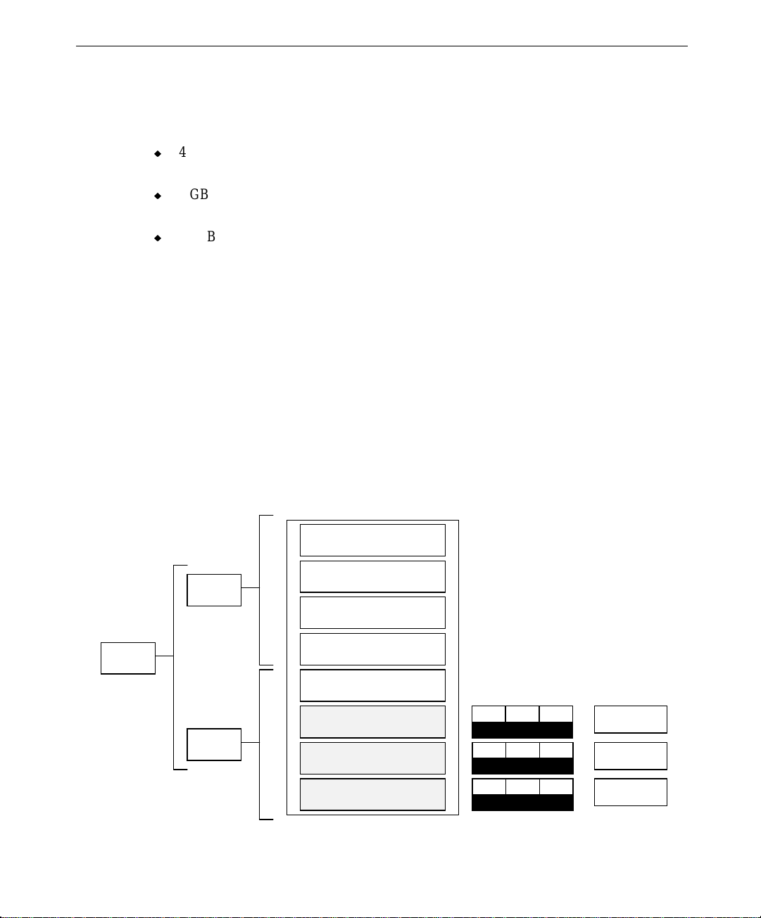
Unpacking the Equipment
The InterServe base unit is set between two foam pieces on the pallet, and other items are
packed in boxes. The pallet with the base unit and boxes is shown in the following figure.

3
Disk Drives
Box
InterServe
Base Unit
Parts Box
Disk Drives
Box
Contents of the boxes are as follows:
u
Parts box -- contains the keyboard, mouse, and keys (one for system power switch and
another for the drive access door); Windows NT Server operating system (compact
disks, floppy diskettes, and documentation), if ordered; Intergraph system software
(diskettes); label sheets for disk drives; and documentation.
u
Disk drives box -- each box contains up to four disk drives and documentation. If you
ordered less than four drives, one of the boxes is empty. Note that if your system is non
RAID then both of the disk drive boxes will be empty.
If you ordered a monitor from Intergraph Computer Systems, it is shipped separately from
the base unit pallet. Its carton contains the monitor, the monitor AC power cord, the video
cable, and monitor documentation.
NOTE If any of the listed items were not delivered, call the Customer Response Center immediately
at 1-800-633-7248.
Save all packaging materials after setting up the system. If you return equipment for repair,
it must be in its original packaging for you to get warranty service (if provided under your
contract agreement).

4
Placing the System
Before you set up your system, determine where you want to place it. Keep these guidelines
in mind:
u
Place the system as close as possible to the proper power outlet. The power cord
connecting the system to the facility power outlet or other power source serves as the
disconnect device.
u
Place the system in an area where air can circulate freely around it.
u
For a deskside installation, the front of the system requires at least twelve inches
clearance, and the back of the system requires at least eight inches clearance.
For rack mounting, ensure that the front and the back of the rack each have 36 inches of
clearance for servicing the installed hardware.
u
Do not expose the system to high levels of dust, smoke, or moisture.
u
Place the system in an area where the temperature range stays between 10 °C and 26 °C
(50 °F and 80 °F). The optimum operating temperature is 21 °C (70 °F).
u
Place the system in an area where the humidity stays between 20 percent and 80 percent
(non-condensing). The optimum operating humidity is 50 percent (non-condensing).
Install the system as described in “Setting up a Deskside System” or “Installing a System
into a Rack.”
Understanding Power Requirements
The following table shows your system’s rated power consumption (load).
Voltage
(Vac)
Frequency
(Hz)
90 60 10 900
100 60 10 1000
120 60 10 1200
220 60 5 1100
240 60 5 1200
254 60 5 1270
The power load of a device is the product of its operating voltage (such as 110 Vac) times its
current (such as 3 Amps). The rated power load of an external option (tape libraries, disk
arrays, and so on) is printed on back of the device.
Rated Current
(Amps)
Rated Load
(VA)

Add the load for each device in addition to the system to determine if the external power
source can handle the load. If it cannot, add an additional power source.
A single 115 VAC branch circuit is not rated to supply enough power to properly operate two
or more systems. If you are not using an external power source, you must plug each system
into its own branch circuit. The systems cannot power on properly if you plug two or more
into the same branch circuit. However, one system plus a low power load device such as a
monitor can be used on the same branch circuit.
If using an external power source with your system, such as an AC distribution box or an
uninterruptible power supply (UPS), review the documentation delivered with the power
source for information about its capabilities.
Setting Up a Deskside System
Intergraph Computer Systems ships the system with a stabilizer plate mounted on the bottom
of the system, as shown in the following figure.
5
Stabilizer Plate

6
To set up the system:
1. Lift the base unit from the pallet and set it upright.
WARNING The base unit is heavy; two people are required to lift it out of the box. Do not let the
base unit drop onto a hard surface, or damage to internal components may result.
2. Remove the plastic bag from the base unit.
3. For dual power supplies, remove four cardboard sheets from the sides of the power
supplies.
4. Connect the cables as described later in this chapter under “Connecting the Cables.”
Installing the System into a Rack
Prepare the System
The system can be installed only in Intergraph’s 17 U and 40 U racks.
To prepare the base unit for rack installation:
1. Place the pallet close to the equipment rack.
WARNING The base unit is heavy; two people are required to lift it out of the box. Do not let the
base unit drop onto a hard surface, or damage to internal components may result.
2. Lift the base unit from the pallet and set it upright.
3. Remove the plastic bag from the base unit.
4. A stabilizer plate is attached on the bottom of all servers. You must remove the plate
before installing the base unit into the rack. Tip the base unit back to expose the
stabilizer plate, and remove the four screws from the stabilizer plate.
CAUTION The two 1/4 turn fasteners on the back of the base unit could be damaged if you let the
system rest completely on the back panel. Support the system in a tipped position while
removing the stabilizer plate.
NOTE The four holes from which the screws were just removed are the same holes used to secure
the base unit to the sliding shelf.
5. Set the unit upright.
6. Install the sliding shelves and other rack mounting hardware as described in the Sliding
Shelf Assembly for Intergraph Racks Installation document.

Install the System
This section describes the installation of the server base unit into an Intergraph 40 U or 17 U
rack.
u
To keep the rack from moving, ensure the front and side stabilizers are fully engaged
and the feet are lowered to the floor before installing equipment into the rack.
u
Install components into the lower sections of the rack first.
u
The base unit weighs 140 pounds (63.3 kg) and is very bulky. Two people are required
to install the base unit into the rack.
To install the base unit into the rack:
1. Remove the screw securing the shelf to the rack as shown in the following figure.
2. Disengage the sliding shelf by lifting the release lever.
Mounting
Hole
7
Alignment
Nodule
Release
Lever
Screw
Sliding
Shelf

8
3. Pull the shelf out until it locks in the extended position. The rear edge of the shelf
should clear the front of the rack by two inches, as shown in the following figure.
WARNING Extend the shelf fully before setting the base unit on it.
Locki ng
Tab
Mount ing Ho le
(Four Total)
Alignment
Nodule (Two)
4. With a person on either side of the base unit, lift the base unit and set it on the extended
shelf.
5. Position the base unit so that the alignment nodules match the holes in the bottom of the
base unit. This ensures the mounting holes are aligned for inserting the screws.

9
6. Secure the base unit to the shelf by installing the four screws -- removed when the
stabilizer plate was removed -- up through the bottom of the shelf into the base unit. To
prevent the base unit from falling, one person should support the base unit while the
other installs the screws.
7. Push the base unit into the rack until it stops.
8. Disengage the locking tab on the sliding shelf and continue pushing the base unit until it
fully retracts and locks into place.
9. Insert the screw under the shelf handle to secure the sliding shelf to the rack.
10. Connect the cables as described next in “Connecting the Cables”.

10
Connecting the Cables
All cable ports on the base unit and other Intergraph equipment are keyed or molded and
clearly labeled to ensure proper cable attachment. If a cable is not attaching easily, ensure
that you are aligning the cable connector correctly with the port.
To connect the cables:
1. Connect the video cable from the monitor to the video out port on the video card located
in the I/O expansion panel. Refer to the following figure.
Video Out
MIDI/Game
Parallel
Microphone
Line In
Line Out
Serial
(COM 2)
Serial
(COM 1)
Universal
Serial Bus
1 & 2
KeyboardMouse
2. Connect the cables for the mouse and keyboard to their ports on the I/O connector panel.
3. Connect the cables for installed option boards as described in the documentation for
those boards.

4. Connect the system power cord to the AC receptacle on the base unit, as shown in the
following figures.
−
For dual power supplies:
AC Receptacle
Dual 550 Wat t
Power Suppli es
11
−
For a single power supply:
AC Receptacle
5. If using an AC distribution box or UPS, connect its power cord to a grounded, three-
prong AC power outlet.

12
NOTE The UPS starts automatically when its power cord is connected to the power outlet. Refer to
the UPS documentation for more details.
6. Connect other cables as necessary for printers (parallel port), external SCSI devices
(SCSI port), and modems or UPS communication (serial ports).
7. Install the disk drives as described next.
Installing Disk Drives
The disk section in the front of the system contains either four or eight disk drive mounting
locations. If your system is configured for RAID, it will contain eight drive slots. The slots
are numbered from 1 to 8, starting with the bottom slot. If you are installing less than eight
drives into the system, install the disk drives starting in slot 1, the bottom slot, and fill each
slot in sequence.
The following figure shows the disk section door and door lock on the system.
Disk Section
Door
Door Lock

The non-RAID disk drive boxes can hold up to four disk drives and the system can
accommodate up to two of them for a total of eight drives. Depending on the configuration,
the system is RAID or non-RAID (JBOD) system. The RAID system uses a 2-channel AMI
RAID controller to provide RAID capabilities such as disk striping, mirroring, and
redundancy. The non-RAID system use a 2-channel Ultra Wide SCSI controller that does
not feature any RAID capabilities.
Each disk drive has a label affixed to the front. The left side of the disk drive label identifies
the disk drive size (in GB). The label has blank spaces for the numbers to indicate the
adapter (ADP), channel (CH), and SCSI ID (ID). Standard disk drives include values for the
adapter, channel, and SCSI ID filled in. Additional disk drives have a blank label which you
must complete after installation.
NOTE A labeling sheet is included in the system parts box.
13
x GB
ADP
CH ID
100
x GB
ADP
Note the following about RAID disk drive and non-RAID disk drives.
u
For a RAID system, three disk drives (with the operating system striped across all three)
are standard. These drives, called boot drives, are labeled with specific adapter,
channel, and SCSI ID. They must be installed in specific slots in the disk section.
Installation details are provided below.
u
For a non-RAID system, one disk drive (with the operating system installed) is standard.
This drive is called the boot drive. It is labeled with specific adapter, channel, and SCSI
ID. The boot drive should be installed in the lowest slot of the disk section. Installation
details are provided below.
CH ID
Install and Label the Disk Drives
The following procedures cover both RAID and non-RAID installations. To install nonRAID drives, both side panels must be removed to gain access to the sides of the JBOD disk
drive housing. Drives are hard mounted in the JBOD housing using four screws (two on
each side) for each drive.
Filled-in Label
Blank Label
To install the disk drives:
1. Open the disk section door on the front of the base unit. The key is provided in the parts
box. The following figure shows the RAID disk section.

14
Slot G uides
Slot 8
Drive
Connector
Port
Slot 1
2. Remove the disk drives from the drive boxes.
3. Do the following when inserting drives into the slots:
−
Extend the latching clips on the drive and align the rails on the side of the drive
with the slot guides. The metal casing of the drive faces up. If you install the drive
reversed, it will not connect to the system.
−
With your thumb, firmly push the drive in the middle between the latching clips
until it slides all the way into the slot and firmly engages the connector.
−
Close the latching clips to lock the drive in the slot.

4. Locate and install the boot drives (those with the completed labels).
−
Install the RAID boot drives into slots 1, 2, and 3 of the disk section, as shown in
the following figure.
Slot 8
15
x GB
x GB
x GB
ADP0CH0ID
ADP0CH0ID
ADP0CH0ID
−
Install the non-RAID boot drive into slot 1 of the disk section, as shown in the
2
1
0
Slot 7
Slot 6
Slot 5
Slot 4
Slot 3
Slot 2
Slot 1
following figure.
Slot 8
Slot 7
Slot 6
Slot 5
x GB
ADP0CH0ID
0
Slot 4
Slot 3
Slot 2
Slot 1
5. Install the remaining disk drives into the slots. Fill each slot upward as you install the
drives. There should be no empty slots between the drives.

16
6. Label the remaining disk drives as follows. A drive labeling sheet is included in the
parts box. Note carefully how the drives should be labeled for each slot.
−
Label RAID disk drives with ADP, CH, and ID numbers as shown in the following
figure.
4
2
1
0
Slot 8
Slot 7
x GB
ADP0CH1ID
x GB
ADP0CH1ID
x GB
ADP0CH1ID
x GB
ADP0CH1ID
Slot 6
4
Slot 5
x GB
ADP0CH0ID
Slot 4
x GB
ADP0CH0ID
x GB
ADP0CH0ID
x GB
ADP0CH0ID
2
1
0
NOTE Do not use the numbers 3 and 7 from the label sheet for RAID systems. IDs 3 and 7 are
reserved for the disk section backplane and the RAID controller. It is acceptable to use ID 3
when configuring a non-RAID system.

−
Label non-RAID disk drives with ADP, CH, and ID numbers as shown in the
following figure. For further details, refer to the guide shipped with the hard disk
drive.
17
Slot 8
Slot 7
Slot 6
Slot 5
Slot 4
Slot 3
Slot 2
x GB
ADP0CH0ID
Additional Information
x GB
ADP0CH
x GB
ADP0CH
x GB
ADP0CH
x GB
ADP0CH
x GB
ADP0CH
x GB
ADP0CH
x GB
ADP0CH
0
1
1
1
1
0
0
0
3
ID
2
ID
1
ID
0
ID
3
ID
2
ID
1
ID
The RAID system boot drives are configured at Intergraph using the MegaRAID utilities.
Additional disk drives supplied with the system are not formatted or configured. You must
configure these drives after configuring system software to make them usable to the system.
Refer to Chapter 3, “Configuring the System,” for more information on configuring and
using the RAID disk arrays.
If your system includes external InterRAID disk cabinets, refer to the InterRAID
documentation for instructions on how to connect them to your system and install additional
RAID disk drives.
WARNING Do not turn on the system power until you are ready to configure Windows NT Server.
If you start the system, and then restart it before completely configuring the operating
system, you will have to reinstall system software as described in Chapter 7,
“Installing System Software.”

18
Checking the System
Before starting the deskside system, review the following items:
u
The cables are properly attached from the base unit to the various options and
peripherals.
u
All disk drives are installed in the proper slots and labeled appropriately.
u
The power cord from the system’s AC receptacle is connected to the correct power
outlet. Note that when power is connected, the LCD panel on the front of the system
will activate even if the power switch is not activated.
Before starting the rack-mount system, review the following items:
u
All hardware is properly and securely installed in the rack.
u
The cables are properly attached from the base unit to the accessories installed in the
rack or in remote locations.
u
The cables attached to the server base unit are routed through the cable handler. Ensure
there is enough cable service loop to allow sliding devices to extend 31 inches.
u
The cables that run along the sides or top of the rack are installed in clips or ties to
secure them in place.
u
All disk drives are installed in the proper slots and labeled appropriately.
u
The base unit is retracted into the rack.
u
The power cord from the AC distribution box or UPS is attached to the correct power
outlet. Note that when power is connected, the LCD panel on the front of the system
will activate even if the power switch is not activated.
WARNING Once you install the equipment into the 40 U rack, do not move the rack. If you must
move it, first remove all equipment, move the rack to its new location, and then reinstall the equipment.
What’s Next?
You can do any of the following to prepare your system for use:
u
If you want to get going with Intergraph’s default setup, go to Chapter 2 to start the
system and go through Windows NT Setup. If you start the system, and then turn it off
before completing the instructions in Chapter 2, you will have to reload the operating
system and system software.

u
Intergraph Computer Systems installs the operating system through Phase 1 of the
Windows NT Setup process. Phase 2 involves establishing a domain name, determining
a security role, and setting up user accounts. If you want to reload the operating system
and system software, instead of completing Phase 2 of Setup, refer to Chapter 7.
u
For RAID systems, the default RAID setup is three disk drives striped to RAID level 5,
including “write through” write policy, and “cached” I/O policy. The default setup is
described in more detail in the section, “Standard RAID Disk Drives Configuration” of
Chapter 3. If you want to reconfigure the RAID setup, refer to the InterRAID
documentation.
19

20

2 Setting Up the Software
This chapter provides instructions for setting up the system software for the server.
Preparing for Setup............................................................................................................ 22
Pre-Installed Software.......................................................................................... 22
Before You Start Setup......................................................................................... 22
Starting the System............................................................................................................ 24
Starting Operating System Setup........................................................................................ 25
Finishing Operating System Setup ..................................................................................... 26
Creating an Emergency Repair Disk..................................................................... 26
Creating System Software Backup Diskettes......................................................... 26
What’s Next?..................................................................................................................... 27
21

22
Preparing for Setup
Your system’s primary system and additional disk drives were formatted and partitioned
before shipment. In Explorer or My Computer, you can right-click a disk drive and click
Properties to display the drive’s partition size and file system format. To view partition and
format information for all disk drives, you can use Disk Administrator. See the operating
system documentation and Help for more information on these tools.
Pre-Installed Software
The operating system and associated system software is pre-installed on the primary hard
disk drive. Intergraph Computer Systems installed the following system software:
u
Driver software for the installed SCSI adapter(s)
u
Driver software for the installed network adapter
u
Driver software for the installed video display adapter
u
Quick-Fix Engineering (QFE) update software (fixes for operating system problems or
limitations, if needed)
u
InterSite software
Before Y ou St art Setup
Before starting the Setup process, have the following documentation available:
u
The Microsoft Start Here document
u
Documentation for the video display adapter delivered with the system
Get and record the following information:
u
Your name, and the name of your
company or organization:
u
For a system running Windows NT,
the CD key from the Windows NT CD
case, or the Product ID Number from
Start Here or the registration card:

If the system is connected to a network, obtain and record the following information from
your network administrator:
u
Computer name for your system:
u
Workgroup name (if the system will be
part of a workgroup):
u
Domain name (if the system will be part
of a Windows NT domain):
u
Security role for your system in the
Windows NT domain -- primary domain
controller, backup domain controller, or
domain server:
u
If your system will be acting as a backup
domain controller or domain server,
username and password of an authorized
domain administrator account:
NOTE Determine the security role for your server before beginning system configuration. You
cannot change a server to a domain controller without reinstalling Windows NT Server. A
domain controller maintains security policy and performs user authentication for a domain.
Servers may be part of a domain, although they do not have to participate in a domain. See
the operating system documentation for a detailed explanation of the differences between
domain controllers and servers.
23
NOTE On a system with Windows NT Small Business Server, the system becomes a domain
controller by default.
If the system is connected to a network that uses the Transmission Control Protocol/Internet
Protocol (TCP/IP), get and record the following TCP/IP information from your network
administrator:
u
Internet Protocol (IP) address for your
system:
u
IP subnet mask for your system:
u
IP domain name for your network:
u
IP address for your network’s default
gateway:
u
IP addresses for your network’s
Domain Name System (DNS) servers,
if any:

24
u
IP addresses for your network’s
Windows Internet Name Service
(WINS) servers, if any:
The Windows NT delivery media contain software and drivers for both Reduced Instruction
Set Computing (RISC)- and Intel-based systems. When installing Windows NT distribution
files, make sure you install them from the \
delivery media. For example, if you are installing a device driver from the Windows NT
CD-ROM, key in the following when prompted for the path:
drive:\i386
where drive is the drive letter for the CD-ROM drive.
Starting the System
To start the system, turn the keyswitch on the front of the system to the ON ( | ) position, as
shown in the following figure. If you have an AC distribution box connected to the system,
make sure its power switch is turned on before you start the system.
I386 directory (the Intel software directory) on the
Keyswitch
OFF
ON
RESTART

Starting Operating System Setup
When you start your system for the first time, you must configure the operating system
software for use. After you first start the system, the Microsoft End User License Agreement
(EULA) screen displays.
25
CAUTION If you purchased a system with Windows NT Small Business Server, read Microsoft’s
Here
document before continuing. Setup procedures for Windows NT Small Business Server
differ from Setup procedures for Windows NT Server.
NOTE Before starting the system for the first time, you may want to learn more about system power,
startup, and shutdown. See Chapter 4, “Using the System,” for this information.
Start
To start the computer and set up the operating system software:
1. Turn on the monitor by pressing its power switch.
2. Turn the keyswitch on the front of the system to the ON ( | ) position. The system starts
and the EULA screen displays on the monitor.
3. Read the terms of the EULA and then follow the instructions displayed on-screen to
complete the Setup process. A Welcome screen displays, then a prompt for user and
organization, and then a prompt for the product ID. Accept the default settings provided
by Setup, except as follows:
−
Setup asks if you want to install networking. If you choose to install networking
(default), choose “Select from list...” when prompted whether to allow Setup to
detect the network adapter. From the list, select “3Com Fast Etherlink XL Adapter
(3C905).” Allow Setup to install this driver software.
NOTE On a system with Windows NT Small Business Server, networking is installed by default and
without user intervention. After Setup completes, go to Network in the Control Panel to set
the system’s network address. See Microsoft’s
Start Here
document.
−
Create an Emergency Repair Disk when prompted.
NOTE On a system with Windows NT Small Business Server, you will create an Emergency Repair
Disk after completing Setup.
−
Enter a password for the Administrator account when prompted.
After you configure networking, you can join a workgroup or domain. You cannot set up a
user account until after you have completed setup and rebooted the system. See Windows
NT Help for details on setting up a user account and joining a workgroup or domain.

26
Finishing Operating System Setup
After operating system Setup is completed, a “Press to finish setup” icon displays on the
operating system desktop. Double-click this icon, or select Programs/InterSite/Welcome
from the operating system Start menu, to display InterSite Welcome.
InterSite Welcome helps you do the following:
u
Create a repair disk for the operating system.
u
Create backup diskettes of device driver software and other system software products.
u
Display an online System Introduction for your system.
u
Learn about Intergraph Computer Systems customer support.
You should take advantage of the tools provided by InterSite Welcome to ensure that your
system is fully ready for use. See InterSite Welcome for more information. Also see the
following sections for information on creating a repair disk and creating backup diskettes.
Creating an Emergency Repair Disk
If you did not create an Emergency Repair Disk during Setup, use the tools provided by
InterSite Welcome to do so. See the operating system documentation and Help for
information on creating an Emergency Repair Disk. You should also update an Emergency
Repair Disk after you finish configuring the system.
In the event of corrupted disk drives, the files on the repair diskettes restore the contents of
the operating system registry at the time the operating system was installed, along with the
standard operating system drivers.
Creating System Software Backup Diskettes
Backup media for some device driver software and system software products are not
delivered with the system. Use InterSite Version Manager, available through InterSite
Welcome, to create system software backup diskettes.
Version Manager lets you create backup diskettes containing device driver software and
system software products that were installed on the system before shipment, and which are
not available on the operating system CD-ROM. You may need these backup diskettes later
-- for example, if you have to reinstall a device driver or the operating system.
NOTE InterServe products are delivered with backup media of all drivers and other system software
products.

NOTE You may not have to create backup diskettes for all system software. If Version Manager
does not list drivers or other system software products, then they are available on the
operating system software CD, or on backup media delivered with the system.
If the system requires Quick-Fix Engineering (QFE) update software, it is included in the
system software available for backup diskette creation. Look for QFE_NTW or QFE_NTS.
QFE update software contains fixes for operating system problems or limitations, and is only
shipped with the system if it is needed. If QFE update software is shipped with the system,
you should create a QFE backup diskette for use if you have to reinstall the operating system.
See Version Manager Help for information on creating system software backup diskettes.
Visit the Intergraph Computer Systems site on the World Wide Web and vendor bulletin
boards for new and updated drivers.
What’s Next?
See the online System Introduction for information on system features and controls.
See Chapter 3, “Configuring the System,” to configure the system for use.
27
See Chapter 4, “Operating Notes,” for related details.

28

3 Configuring the System
Follow the instructions in this chapter to configure the InterServe 800 SL for use.
Configuring the Video Display........................................................................................... 30
Changing the Default Video Display Driver ......................................................... 30
Correcting Video Display Problems...................................................................... 30
Installing MegaRAID Power Console Software.................................................................. 31
Configuring Additional Drives for a RAID Disk Array ...................................................... 32
Basic RAID Hardware Information ...................................................................... 32
Standard RAID Disk Drives Configuration........................................................... 33
Additional RAID Disk Drives Configuration........................................................ 35
Ensuring Correct PC Card Hard Disk Operation ................................................................ 36
Installing and Configuring LanSafe UPS Software............................................................. 37
Disabling Command Queuing............................................................................................ 38
Installing QFE Update Software......................................................................................... 38
Creating an Emergency Repair Disk .................................................................................. 39
Installing the InterSite Server Monitor ............................................................................... 39
Getting Operating System Updates..................................................................................... 39
29

30
Configuring the Video Display
The first time you start the system, it uses the installed video display adapter running at
1024 x 768 to run the video display. For the system to use the installed video adapter at
other display resolutions, you must configure the video display driver. Refer to the
documentation delivered with the video display adapter for information about available
settings. For information on using the Display Properties dialog, refer to the operating
system documentation and Help.
Changing the Default Video Display Driver
After configuring the video display and restarting the system, you should configure the
system to use the Intergraph video display driver by default.
To change the default video display driver:
1. Open System in the Windows NT Control Panel. The System dialog displays.
2. Under Operating System, select the Startup list; then select the appropriate non-VGA
Windows NT Server option from the displayed list.
3. Select OK.
Correcting Video Display Problems
If the system’s video display is black, not synchronized, or distorted after you restart the
system, you may have a video configuration problem.
Do not press
correct the problem by using the Last Known Good option to return the system to the last
known good configuration recorded by Windows NT.
To use the Last Known Good option:
1. Power down and restart the system.
2. Press the space bar at the following prompt:
Press space bar NOW to invoke the Last Known Good Menu
If using the Last Known Good option fails to correct the video display problems, you can
obtain a functional video resolution by restarting the system in VGA mode.
CTRL+ALT+DEL to log on to the Windows NT operating system. Instead, try to

To restart the system in VGA mode:
1. Power down and restart the system.
2. At the boot screen, select the VGA mode option.
After logging on to Windows NT in VGA mode, check for the following common
configuration problems and solutions:
u
A multi-sync monitor is selected, but a graphics display device with different video
timings (such as an Intergraph InterVue monitor) is connected to the system. Select the
appropriate monitor type as described previously.
u
The monitor selection is inappropriate for the monitor connected to the system. Select a
new monitor.
u
There is not enough video display memory to support the selected graphics resolution
and color depth. Install and reconfigure the video display to use a lower resolution and
color depth.
Restart the system and, when the boot screen displays, select the appropriate non-VGA
Windows NT Server to use the reconfigured video display driver. If problems persist,
contact the Intergraph Customer Response Center at 1-800-633-7248 for help.
31
Installing MegaRAID Power Console Software
NOTE This section only applies to systems that use RAID disk drives.
Intergraph Computer Systems preinstalls MegaRAID Power Console software on RAID
systems. In the event you have to rebuild your system and reinstall Windows NT Server, you
must install the MegaRAID Power Console software after configuring Windows NT Server.
Install the software from the backup diskette you created using Version Manager. Refer to
Version Manager Help for more information about using Version Manager.
To install MegaRAID Power Console software:
1. Log on to Windows NT using an administrative account.
2. Insert the diskette containing the MegaRAID Power Console utility into the floppy disk
drive.
3. Run
4. Respond yes or no appropriately to the questions about Windows NT. At the Welcome
SETUP.EXE on the diskette.
dialog, select Next. The MegaRAID Install Destination Path dialog displays.

32
5. If you agree with the destination directory, select Next. Otherwise, select Browse and
enter a new directory path. The files are copied in the directory named \
MEGARAID (or
where you specify) and the MegaRAID program group is created. Setup also displays a
message that the driver is present on the system.
For information on configuring and using the RAID disk drives, and for information on
using the MegaRAID Power Console, refer to the InterRAID documentation delivered with
the system.
Configuring Additional Drives for a RAID Disk Array
NOTE This section only applies to systems that use RAID disk drives.
This section describes the RAID hardware used in the system, explains the standard RAID
disk configuration, and provides guidelines to configure additional RAID drives. The
standard RAID hardware is pre-configured by Intergraph Computer Systems before
shipment. The following information is provided to help you understand how RAID is
implemented, which should be valuable if you need to configure additional RAID hardware.
Basic RAID Hardware Information
The InterServe 800 SL systems contain three main RAID hardware components:
u
An internal disk section
u
Three or more RAID disk drives
u
One or more RAID controllers (also known as adapters)
The disk section has eight slots for installing RAID disk drives. The slots are numbered
from 1 to 8, starting with the bottom slot. Each slot also has a corresponding SCSI ID
number, which is determined by the hardware configuration of the RAID section itself and
the installed RAID controller.
u
For technical information about the disk section, refer to the System Reference.
u
For technical information on the RAID controller, refer to the InterRAID
documentation.

The standard configuration includes three RAID disk drives for the disk section and one
RAID controller. The disk drives are installed in slots 1, 2, and 3 of the RAID section, and
each one has a label to identify the drive, such as:
33
04 GB
ADP
1
CH
0
ID
The spaces above ADP, CH, and ID are filled in before shipment to identify the drives.
u
ADP means the RAID controller (adapter) number connected to the RAID section.
u
CH means the RAID SCSI bus channel of the adapter (each adapter has two channels).
u
ID means the identification number of the drive in the slot.
NOTE When the standard disk drives are configured by Intergraph Computer Systems (as described
below), they assume the SCSI ID number of the RAID section slot.
The RAID section is connected to the RAID controller by internal SCSI cables.
Standard RAID Disk Drives Configuration
The following figure shows the RAID section slots, with their attached controller (ADP), and
the channel (CH) and SCSI ID (ID) designations. The standard disk drives are installed in
slots 1, 2, and 3, as shown by the shaded slots. Note that the SCSI IDs 0, 1, 2, and 4 are
repeated for each channel.
Slot 8
SCSI ID 4
ADP 0
CH 1
CH 0
Slot 7
Slot 6
Slot 5
Slot 4
Slot 3
Slot 2
Slot 1
SCSI ID 2
SCSI ID 1
SCSI ID 0
SCSI ID 4
SCSI ID 2
SCSI ID 1
SCSI ID 0
34
All three drives in the disk section are packed as one logical drive (via MegaRAID Power
Console). This makes the drives in the system appear as one partition in Windows NT Disk
Administrator.
u
4 GB disk drives result in a 12 GB partition (8 GB partition if the RAID Level is set to
RAID 3 or RAID 5). RAID 5 is the default.
u
9 GB disk drives result in a 27 GB partition (18 GB partition if the RAID Level is set to
RAID 3 or RAID 5). RAID 5 is the default.
u
18 GB disk drives result in a 54 GB partition (36 GB partition if the RAID Level is set
to RAID 3 or RAID 5). RAID 5 is the default.
The MegaRAID BIOS and Power Console programs let you view and change the way in
which the RAID controller treats the RAID drives. For example, you can change the
configuration so that each drive is a separate array, instead of all three being in one array.
When using MegaRAID BIOS or Power Console, the program identifies the drives as Ax-N.
Ax represents the arraythat the drives are a part of, and N represents the sequential disk
drive number within the array.
NOTE For detailed information about using the MegaRAID BIOS or Power Console, refer to the
InterRAID documentation.
ADP 0
The following figures show the correlation between the disk drives (labeled), their slot
location (shaded areas), and how they are identified in MegaRAID BIOS and Power Console
(MegaRAID ID).
Slot 8
Slot 7
CH 1
Slot 6
Slot 5
Slot 4
Slot 3
CH 0
Slot 2
Slot 1
SCSI ID 4
SCSI ID 2
SCSI ID 1
SCSI ID 0
SCSI ID 4
SCSI ID 2
SCSI ID 1
SCSI ID 0
Disk Label:
ADP0CH1ID
ADP0CH1ID
ADP0CH1ID
MegaRAID
ID:
2
1
0
A0-2
A0-1
A0-0

The default RAID configuration for the three standard RAID drives is as follows:
u
RAID level - 5
u
Write policy - write through
u
I/O policy - cached
u
Device Spinup - two drives every six seconds
u
Ultra SCSI - enabled
If you modify the RAID configuration, and want to return to the default settings, use the
following procedure. For details about using MegaRAID BIOS utility, refer to the
InterRAID documentation.
To reset the default RAID configuration:
1. Reboot the system.
35
2. When prompted, press
CTRL+M to enter the MegaRAID utilities.
3. Use Configuration/Easy Configuration to set up one 8 GB array to RAID level 5, write
through, and cache I/O.
4. Under Objects/Adapter/Chipset Type, ensure that Others is selected.
5. Under Objects/Adapter/Alarm Control Type, ensure that the MegaRAID onboard alarm
is disabled.
6. Under Objects/Adapter/Spin Up Time/Spinup Parameters, set the parameter to two
drives every six seconds.
7. Under Objects/Adapter/Ultra SCSI, ensure the Ultra SCSI is enabled.
8. Reboot the system.
Additional RAID Disk Drives Configuration
If your system was shipped with more than three RAID drives, then the extra drives are not
configured. Before you can use them, the additional RAID drives must be configured into
one or more arrays using the MegaRAID BIOS or Power Console. The following steps
provide the general guidelines. For every possible configuration, refer to InterRAID
documentation for detailed instructions.
To configure additional drives:
1. Start the MegaRAID Power Console utility from the MegaRAID program group.
2. If your system has multiple RAID controllers, select the one to which the unconfigured
RAID drives are connected.

36
3. From the Adapter menu, select the Configuration submenu, then select the Custom
Configuration option.
4. Select the unconfigured RAID drives (shown as READY) and configure them into one
or more arrays as desired.
CAUTION Do not place different size drives into the same array. If you do, the size of the larger drives
will be truncated to that of the smaller drives, and the remainder will be unusable.
5. When the configuration has been applied, the Create Logical Drive dialog displays. Set
the logical drive options to your desired settings.
NOTE Before you select Apply, note the amount of disk space displayed. If this amount changes
when you select Apply, select Apply again to ensure the changes take effect.
6. Select Apply, and then select OK to save the configuration and initialize the drives.
Ensuring Correct PC Card Hard Disk Operation
The optional PC Card adapter is used with devices based on standards developed by the
Personal Computer Memory Card International Association (PCMCIA). Windows NT
provides support for PC Card devices. Refer to the operating system documentation and
Help for more information on PC Card device support.
If you will be using a PC Card hard disk device (ATA or AT type), make sure the device
drivers that control PC Card hard disk operation are set to start correctly. Set the Atdisk
device to start as a System device, and set the Pcmcia device to start as a Boot device. Do
this before inserting a PC Card hard disk device in the PC Card adapter. If you do not,
anomalous behavior may result -- for example, the PC Card hard disk drive may not be
detected by the operating system, or may be detected as the system drive (drive C).
NOTE You must shut down the system before inserting a PC Card device in the PC Card adapter.
When you restart the system, Windows NT will recognize the PC Card device.
To change startup type for device drivers that control PC Card hard disks:
1. Open Devices in the Control Panel. The Devices dialog displays.
2. Highlight the Atdisk device in the Device list; then select Startup. The Device dialog
displays.
3. Under Startup Type, select System; then select OK.
4. Highlight the Pcmcia device in the Device list; then select Startup. The Device dialog
displays.
5. Under Startup Type, select Boot; then select OK.
6. In the Devices dialog, select Close.

Installing and Configuring LanSafe UPS Software
Systems equipped with a uninterruptible power supply (UPS) are shipped with LanSafe III
software to configure and monitor operation of the UPS. The software must be installed
before you can configure and monitor UPS operation. The following instructions assume
that you are installing LanSafe III UPS software on your system for the first time.
To install LanSafe III UPS software:
1. Insert the LanSafe III CD-ROM into the CD-ROM drive.
37
2. Run
3. When the Welcome dialog displays, select Install.
4. Select Full Installation to install the software onto the server. If you are installing
NOTE If you select Remote Services, Setup asks for a location to install the files. Select the default
location, or enter an alternate pathname; then select Continue. After the software is installed,
shut down and restart the system.
5. When asked if the computer is part of a UPS group, select No; then select Continue.
6. Select Power Rite Pro II; then click Continue.
7. Select the COM port to be used; then select Continue.
8. Enter an access code to safeguard the UPS operation; then select Continue.
9. Select Shutdown Timing Operations; then select Continue.
10. Select Yes for the Autoload Option; then select Continue.
11. A dialog asks for a location to install the files. Accept the default location, or enter an
12. Select LanSafe III Power Monitor Service and click Startup. The Service dialog
SETUP.EXE in the NTWIN directory on the CD-ROM drive.
LanSafe III onto a remote system, select Remote Services; then select Continue.
alternate pathname; then select Continue. When the software is installed, open the
Control Panel and double-click Services. The Services dialog displays.
displays. Verify that the Allow Service to Interact with the Desktop check box is
selected.
13. Click OK to close the Service dialog, and click OK.
14. Shut down the system.
15. Verify that the serial cable is connected as described in the LanSafe III software manual,
and that all AC power cables are connected to AC receptacles on the back of the UPS.
16. Restart the system.
Refer to the LanSafe III documentation for instructions on using the LanSafe III software.

38
Disabling Command Queuing
To improve standalone system performance and to improve performance with some highperformance SCSI peripherals, you should disable command queuing in the Windows NT
Registry.
WARNING Do not change values in the Registry other than as directed. If you introduce incorrect
values into the Registry, you may cause serious operating system problems, and you
may have to reinstall Windows NT. If you change values in the Registry that make
your system unusable, you may be able to restart the system and use the Last Known
Good Configuration option to undo the damage. Refer to the operating system
documentation for more information on the Last Known Good Configuration option.
To disable command queuing:
1. Start the Registry Editor (
2. Open the following subkey in the Registry:
HKEY_LOCAL_MACHINE\SYSTEM\CurrentControlSet\Services\aic78xx
3. From the Edit menu, select the Add Key.
4. Type Device into the Key Name box, and then select OK. Do not set a Class value.
Open the following subkey in the Registry:
HKEY_LOCAL_MACHINE\SYSTEM\CurrentControlSet\Services\aic78xx\
Device
5. From the Edit menu, select Add Value.
6. Type DisableTaggedQueuing into the Value Name box.
7. Select REG_DWORD for the Data Type, and then select OK.
8. Type 1 into the Data box.
9. Set the Radix value to Hex, and then select OK.
10. Exit from the Registry Editor and restart the system.
REGEDT32.EXE) to open the Registry.
Installing QFE Update Software
If the system was shipped with Quick-Fix Engineering (QFE) update software, you created a
QFE diskette using Version Manager. QFE update software contains fixes for operating
system problems or limitations on your Intergraph system, and is only shipped with the
system if it is needed. If you have a QFE diskette, insert it into the floppy disk drive. Refer
README.TXT file on the QFE diskette for instructions to update the system.
to the

Creating an Emergency Repair Disk
You should create an Emergency Repair Disk after you finish configuring the system. The
files on the Emergency Repair Disk can restore a damaged registry to its original contents
(that is, at the time Windows NT was installed), along with the standard Windows NT
drivers.
39
Use the
to update the Emergency Repair Disk any time you change the system’s configuration. You
should also make and keep a backup copy of the Emergency Repair Disk.
Refer to the operating system documentation and Help for information on creating and using
an Emergency Repair Disk.
RDISK.EXE utility to create an Emergency Repair Disk. You can also use this utility
Installing the InterSite Server Monitor
Your InterServe server may have shipped with an installed InterSite Server Monitor (ISM)
board. For instructions to install and configure the ISM software, and for information on
using the ISM with your server, refer to the InterSite Server Monitor documentation included
with your system.
Getting Operating System Updates
Microsoft Service Packs and Service Releases contain the latest improvements and system
fixes for Microsoft operating systems. Service Packs and Releases are created by Microsoft
for post-release support. You can get then from Microsoft’s World Wide Web and FTP sites
free of charge.
CAUTION If Intergraph Computer Systems provides a Service Pack through the IBBS or with a product,
it has been certified against Intergraph hardware as described in the announcement of its
availability. If you obtain a Service Pack from any other source, be aware that it may not be
certified against your Intergraph hardware.

40

4 Operating Notes
Now that your system is up and running, and all the software is configured, use this chapter
to become familiar with the InterServe 800 SL and its user features.
Starting and Stopping the System ...................................................................................... 42
Status LEDs....................................................................................................................... 43
Disk Activity LEDs (RAID Systems).................................................................................. 44
System Alert...................................................................................................................... 45
LCD Screen....................................................................................................................... 46
System Status Menus......................................................................................................... 50
RAID Section Menus......................................................................................................... 58
Using InterSite Programs................................................................................................... 61
Additional User Information .............................................................................................. 62
41

42
Starting and Stopping the System
The following figure shows the system power keyswitch on the front of the system.
Keyswitch
OFF
ON
RESTART
After the system is running, you can restart the system or shut it down and power it off
completely. Wait at least 30 seconds before restarting the system to allow the InterSite
Server Monitor software to function correctly, the power supplies to stabilize, and the disk
drives to stop spinning.
u
To restart the system, click on Start on the video screen and select Shutdown. Click on
Shutdown and Restart. If the system becomes unresponsive you must turn the key to the
o position and wait for at least 4 seconds for the system to shut down. After the system
shuts down, wait at least 30 seconds before turning the system on again. Then turn the
key back to the | position.
u
To stop the system, perform an orderly shutdown and then turn the key to the o position.
An orderly shutdown consists of stopping all running applications and logging off
Windows NT by clicking on Start on the video screen and then selecting Shutdown.
Choose Shutdown.

NOTE The backlight will extinguish, but the LCD panel will continue displaying system information
after stopping the system.
If external InterRAID disk cabinets are connected to the system, always power on or off the
system in the following sequences:
u
Power on the InterRAID cabinets, listen for the audible beep, then power on the system
base unit.
u
Power off the system base unit (as described previously), then power off the InterRAID
cabinets. If you power off the InterRAID cabinets first, the RAID controller will read
the drives in those cabinets as dead the next time you power on the system. If this
happens, refer to the InterRAID documentation for drive recovery procedures.
The LCD screen displays the system status after the system is powered on. Refer to “LCD
Screen” later in this chapter for more information about the messages displayed on the LCD
screen.
WARNING The side panels must remain installed on the system while it is powered on. The
panels are required to maintain proper airflow for the system’s internal components.
If you operate the system with either side panel removed, components may overheat
and cause system damage.
43
NOTE If the LCD panel board fails, then the system will not power on when you turn the keyswitch
to the ON position. To work around this problem, turn the keyswitch and hold it in the restart
position for at least four seconds. The power supplies will turn on so you can use the
system. However, the LCD panel will not display any text, and Hardware Monitor will not be
able to report complete system status. The LCD panel board must be replaced.
Status LEDs
The Light-Emitting Diodes (LEDs) on the front of the system help you determine system
status at a glance. If any of the LEDs are amber, there is a problem in part of the system
hardware. The four status LEDs are:
System power - green when power is on, off otherwise.
RAID Disk array status - green if all disks OK, amber if otherwise; alternating
between green and amber if firmware checksum error occurs. This LED will be OFF
in a non-RAID system.
Power Supply Status - green if all supplies OK, amber if otherwise.
Fan Status - green if all fans OK, amber if otherwise.

44
Note the following:
u
If the fan status LED is amber and the power supply status LED is green, it is possible
that the problem is a fan inside the power supply, rather than a main cooling fan. Check
the fan and power supply status menus on the LCD panel to determine the problem.
u
If the disk array LED indicates firmware checksum error, call the Customer Response
Center at 1-800-633-7248.
u
The disk array status LED functions only if the system uses RAID drives.
The following figure shows the location of the status LEDs.
Status LEDs
When the status LEDs indicate a failure condition (amber), use the LCD screen for more
information about the problem. Additionally, an alarm sounds a continuous beep if a
problem occurs in the system or internal RAID. You can turn off the beep using the
Alert/Alarm command (for system hardware errors) or the Turn Off Alarm command
(for RAID errors). Refer to the sections “Configure the Audible Alarm Operation” or “Turn
Off the RAID Alarm” later in this chapter.
Additional disk activity LEDs, as described next, are located to the left of each slot of the
disk section.
Disk Activity LEDs (RAID Systems)
The eight disk status LEDs, located to the left of the disk drive slots, indicate SCSI bus
activity for each of the installed drives. The following table shows the status indications for
disk drives in a RAID system.
LED Color
Steady green Disk drive ready and assigned to an array
Blinking green Disk drive ready, but not assigned to an array, such as
Meaning
a hot spare

LED Color Meaning
Steady amber Disk drive rebuild in progress, or critical (degraded)
array
Blinking amber Disk drive failed
Off Disk drive not installed or not seated
Sy stem Aler t
To ensure system security, the InterServe includes a system alert that detects and reports
hardware faults such as power supply failures. Also, conditions that may lead to component
failure, such as excessive room temperature, are detected. System intrusions include opening
the drive access door and removing either side panel. You can disable one or both functions
of the system alert using the system LCD screen. If the system alert is disabled, hardware
faults and intrusions are not detected.
NOTE As long as the LCD screen displays text (the system can be off, but the circuit breaker switch
is on), intrusions can be logged.
You can configure the InterSite Server Monitor/Watchdog software to notify you if an alert is
triggered. When a hardware fault occurs, the system alert sounds an alarm. Refer to the
printed and online documentation delivered with the InterSite Server Monitor and Watchdog
software for more information about notification.
45
The intruder alert can be temporarily defeated so you can work on the system without having
to disable the intruder alert. If a password has been set, the password prompt for temporary
defeat automatically displays when you open the drive access door. Assuming the system
alert is enabled and a password has been set, you must defeat the alert immediately after
opening the drive access door.
NOTE Defeating the alert is not the same as disabling the alert.
and the alert automatically resets when the door is closed. When you open the drive access
door, an intrusion is reported to Event log, but the system does not sound the alarm nor send
the notification.
reported to the Event Log. If the alert is disabled, it must manually be enabled to detect and
report intrusions. Refer to “Enable and Disable the Intruder Alert” later in this chapter for
instructions.
Disabling
the alert means that intrusions are not detected, and therefore not
To defeat the intruder alert during normal system use:
1. When you open the door, the LCD panel displays a screen that lets you enter the
password to temporarily defeat the alert.
Defeating
is a temporary measure,
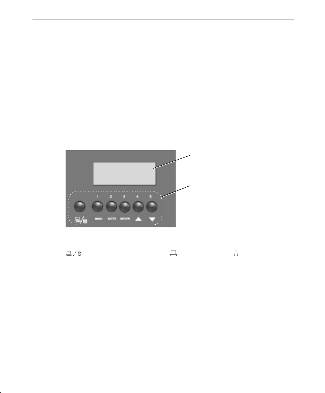
46
2. Enter the correct password. Refer to “Entering a Password when Prompted” and to “Set
the System Monitor Firmware Password” later in this chapter for more information
about passwords.
3. When you close the drive access door, the alert resets.
LCD Screen
The LCD screen displays overall system and specific component information through a set of
menus that apply to the base unit and to the disk section (for RAID systems only). Both
types of power supplies, 300 Watt or 550 Watt, allow the LCD to be on when the system is
plugged in. Status information is available even if the system is powered off or not running
an operating system. The six menu buttons below the LCD screen, as shown in the
following figure, let you navigate the menus and information that displays on the screen.
LCD
Screen
Menu
Buttons
The LCD screen menu buttons are:
Switches between the System menus and the RAID menus, indicates a
complete password, and returns you to the previously used menu.
MENU Displays the menu options for the system status or RAID status.
ENTER Activates the selected menu item.
ESCAPE Returns you to the previous menu.
∆
∇
Moves the cursor up the current menu choices.
Moves the cursor down the current menu choices.
By design, some of the buttons do not function in certain menus. For example, the arrow
buttons do not work in the main display screens. Also, when setting a password, each
button’s function changes. Refer to “Entering a Password when Prompted” later in this
chapter for instructions.

You can use the LCD screen and buttons when the system is powered off, but some of the
status options report a message such as Sys. Off. When the system is powered off, the
LCD screen is not lit, but the displayed messages are visible. The LCD screen lights bright
green when the system is powered on.
The following sections describe the startup messages displayed on the LCD screen, and
provide an overview of the information and menus you can use under the system status
menus and the RAID status menus.
NOTE Information about the disk subsystem does not display if the system is non-RAID.
Startup Messages
When you turn the circuit breaker switch to the On position, the following messages display
on the LCD screen:
System Monitor
Initializing...
47
InterServe 800SL
System Status Okay
Note the following details about the message displayed on the second screen:
u
First line shows the product name.
u
Second line shows:
−
System Status Okay when all internal components are functioning, and
temperatures are at normal levels.
−
System Status Warning if conditions indicate a possible hardware error. The
Warning message is accompanied by an audible beep every eight seconds. Press
the
MENU button and use the System Status menus to determine the hardware at
fault.
−
System Status FAILURE if an error has occurred. The FAILURE message is
accompanied by a continuous audible beep. Press the
MENU button and use the
SYSTEM STATUS menus to determine the hardware at fault.
−
System Monitor, if the system polling function has been disabled. Refer to
“Change the Polling Interval” later in this chapter for more information.

48
When you turn the keyswitch to the On position, the LCD powers on. If the system uses
RAID drives, the following messages display (Otherwise, the above message remains.):
TESTING ROM
TESTING SCSI ACCESS
STARTING DUAL BUS
CONFIGURATION
InterRAID-8
Status: OK
The InterRAID-8 Status message displays until you press the SYSTEM/RAID button to see
the system status menus, or the
displayed in the system status menus and the RAID status menus are listed in “System Status
Information” and “RAID Status Information” as follows.
System Status Information
The following table provides an overview of how to use the configurable options and view
status information for the system.
What do you want to do?
Enable and disable the
intruder alert
Configure the audible
alarm operation
View the internal
temperatures or change the
temperature scale
View the fan status
MENU button to see to the RAID status menus. The menus
Follow this menu path See page
Alert/Alarm > Intruder Alert >
Enable/Disable
Alert/Alarm > Audible Alarm > Sound
Alarm Upon
System Status > Temperature
System Status > Fans
51
51
52
53

49
What do you want to do? Follow this menu path See page
View the power supply
status
View the voltage status 550 Watt power supplies
only
View the system power
status
View power distribution
board information
View LCD board
information
Set the system monitor
firmware password
Change the polling interval
Change the ambient heat
threshold
View the state of the
system monitor firmware
when last rebooted
Manually reboot the system
monitor firmware
System Status > Power Supply
System Status > Voltages
System Status > Sys. Power
System Config. > Power Plane
System Config. > LCD Display Panel
Utility > Set Password
Utility > System Status Poll
Utility > Heat Threshold
Utility > Last Reboot Boot State
Utility > Firmware Reboot
53
55
55
55
56
56
56
57
58
58
RAID Status Information
The following table provides a view of how to use the configurable options and view status
information for the RAID disk section. This information is not available for non-RAID
systems.
What do you want to do?
Turn off the RAID alarm
View RAID configuration
information
View the last POST results
View the internal
temperature
View SCSI ID information
View the internal heat
threshold
Follow this menu path See page
TURN OFF ALARM
HARDWARE MENU > CONFIGURATION INFO
HARDWARE MENU > POST RESULTS
HARDWARE MENU > INTERNAL TEMP
OPTIONS MENU > SCSI ID MENU
OPTIONS MENU > HEAT THRESHOLD
59
60
60
60
60
61

50
NOTE Information about the disk subsystem does not display if the system is non-RAID.
NOTE The RAID status information cannot be displayed unless the system is powered on.
System Status Menus
The system status menus let you define how the intruder alert and audible alarm operate,
view hardware configuration details for the system, and define other system monitor
firmware operation. If the LCD panel displays RAID status line or RAID menus, press the
SYSTEM/RAID button to switch to the system status menus. The system status main menus
selections are as follows:
Alert/Alarm
System Status:
System Config.
Utility
u
Alert/Alarm lets you temporarily defeat the alarm for the intruder alert, and you can
disable the intruder alert so that no intrusions are reported. The alert is enabled by
default. You can also configure the alarm to sound upon detection of a hardware fault
(failure of power supplies, fans, and so on) and intrusion.
status
u
System Status lets you view the status of internal system components. If a problem
is detected, then the this line displays WARN, or FAIL to show that one or more
components need attention. Otherwise, it displays Okay.
u
System Config. lets you view information about the system boards, including board
revision, and applied ECO level.
u
Utility lets you establish a firmware protection password, view the system state when
it was last rebooted, and reboot the firmware.
A cursor appears to the left of the menu options. Press the arrow buttons to move the cursor
to an option, then press the ENTER button to select it.
Entering a Password when Prompted
Some commands require entering the password before the system accepts a change or before
a command takes effect. If a password is not set, the change or commands take affect
without further prompting. When asked to enter a password, use the menu buttons labeled
1 through 5. Press the
The password prompt for the command remains on the screen until you give the proper
password. If you do not key in a password within 16 seconds, a continuous beep begins.
SYSTEM/RAID button to complete the password.

Enable and Disable the Intruder Alert
The intruder alert is enabled by default. Once it is disabled, no intrusion information will be
sent to the operating system Event Log, and the intrusion does not trigger a response from
InterSite. The intruder alert must be enabled for the system to detect intrusions.
Path: Alert/Alarm > Intruder Alert > Enable/Disable
51
1. When the cursor is by Alert/Alarm press
Intruder Alert
Audible Alarm
2. Press
ENTER on Intruder Alert. The screen displays
Temporary Defeat
Enable/Disable
State: Enabled
3. Move the cursor to Enable/Disable and press
and Disabled. Key in the password to change the state, if prompted. If you do not key
in the correct password within 16 seconds, the previous menu screen displays.
Configure the Audible Alarm Operation
Path: Alert/Alarm > Audible Alarm > Sound Alarm Upon
1. When the cursor is by Alert/Alarm press
2. Move the cursor to Audible Alarm and press
Sound Alarm Upon . .
Status Error: Yes
Intruder: Yes
3. Move the cursor to Status Error and press
Key in the password to change the state, if prompted. When set to Yes, any detected
error causes an audible alarm to sound.
ENTER. The screen displays
ENTER to switch between Enabled
ENTER.
ENTER. The screen displays
ENTER to switch between Yes and No.
4. Move the cursor to Intruder and press
ENTER to switch between Yes and No. Key in
the password to change the state, if prompted. When set to Yes, the alarm sounds 15
seconds after an intrusion is detected.

52
View the Internal Temperatures or Change the Temperature Scale
Path: System Status > Temperature
Temperature: status displays a general indication of system temperature. When the
sensor detects normal temperatures, this line displays Okay. If Wm or HOT displays, the
internal sensor is reporting a problem. Press
the specific status for the sensors:
Ambient: value status (Ok, Wm, or HOT)
Scale: value (Fahrenheit or Celsius)
The temperature displays for the system’s sensor. Normal temperatures are indicated by Ok.
The following table states the warm and hot (unsafe) temperatures for the sensor.
ENTER at the TEMPERATURE option to display
Sensor
Ambient Next to drive access door (room air
Location Warm (Wm) Hot (Hot)
32 °C (90 °F) 35 °C (95 °F)
temperature)
CAUTION Temperatures that are approaching the unsafe levels are indicated by Wm. Any sensor that
reports a
fans are working. If room temperature is less than 80 degrees Fahrenheit and the fans are
spinning, the fan speed may be too slow. Call the Customer Response Center at
1-800-633-7248.
WARNING If a sensor reports
could damage internal components. If the cause of the hot temperature condition is
not related to the room environment, call the Intergraph Customer Response Center.
NOTE The threshold for the Ambient sensor can be changed. Refer to “Change the Ambient Heat
Threshold” later in this chapter. The thresholds for the internal sensors cannot be changed.
NOTE Server Monitor can be configured to power off the system automatically when the system
board temperature sensors report
Wm status should be monitored closely. Adjust room temperature and ensure the
HOT, power off the system to protect it from overheating, which
HOT temperatures.
The Scale option lets you change the displayed temperature unit from degrees Fahrenheit
to degrees Celsius. Move the cursor to Scale and press ENTER. The temperature scale
switches between Fahrenheit and Celsius. This option does not affect the temperature
reported for the disk drive section under the RAID status menus.

View the Fan Status
Path: System Status > Fans
Fans: status displays the RPM speed and working status of the three main cooling fans.
When the fans are operating properly, Ok displays. If XX FAILURES is displayed, then one
or more of the cooling fans is generating a problem. When the system is not powered on, the
fan status displays Off.
For systems with the 2 hot-swap supplies, there will only be three system fans: upper, mid
#1, mid #2. The case below still applies to systems with the single fixed supply. Press
ENTER when the cursor is by FANS to see the status for each fan. The following screen
displays:
UPPER: speed status (Off, Ok, BAD)
MID #1: speed status (Off, Ok, BAD)
MID #2: speed status (Off, Ok, BAD)
LOWER: speed status (Off, Ok, BAD)
When the status is Ok, the fan speed is adequate to provide cooling. The normal speed for
each fan is 1950 RPM. If the speed decreases below 1680 RPM, the status BAD displays.
Replace any fan that reports BAD, or shows a continual decline in fan speed.
53
NOTE If the 12 V rail from the power supply goes out of tolerance, the main fan speed will decrease.
In this case, the power supply needs to be replaced, rather than the fans. The power supply
status and voltage status will report failure in this case also.
View the Power Supply Status
The information provided for systems with dual 550 Watt power supplies differs from a
system with a single 300 Watt power supply. Both cases are described in the following
sections.
System with Dual 550 Watt Power Supplies
Path: System Status > Power Supply
Power Supply: status displays Okay, WARN, or FAIL. If WARN displays, a rail in the AC
or DC lines has fallen out of tolerance. You can check the AC or DC status for more
information. If FAIL displays, a fan inside the power supply has failed, or one of the power
supplies has completely failed.
CAUTION Call the Customer Response Center at 1-800-633-7248 to report the failure and to obtain a
replacement power supply.

54
NOTE If Fan Status shows a failure and the Power Supply Status shows a failure, and the
fan status LED is amber while the power supply status LED is green, then this means a fan
inside the power supply is bad.
To view specific power supply status, move the cursor to Power Supply and press ENTER.
The screen displays:
Supply #1: status <Absent, Okay, or FAIL>
Supply #2: status <Absent, Okay, or FAIL>
To view specific power supply information, press
ENTER when the cursor is by either
Supply #X: status line. Supply #1 is the left power supply, when viewed from the back of
the system. The following information displays for the selected power supply:
AC: status (Absent, Ok, or FAIL)
DC: status (Off, Absent, Ok, or FAIL)
Fan #1: speed status (Off, Ok, or BAD)
Fan #2: speed status (Off, Ok, or BAD)
If the AC or DC status reports a failure, but the fans are still working, do not remove the
power supply. Remove the failed power supply only when the replacement power supply is
available for installation.
Fan #1 and Fan #2 show the status of the fans inside the power supply. When the status
is Ok, the fan speed is adequate to provide cooling. The normal speed for each fan is
3600 RPM (± 240 RPM). If the speed decreases below 2640 RPM, the status BAD displays.
Replace the power supply if one of its fans reports BAD, or shows a continual decline in fan
speed.
System with Single 300 Watt Power Supply
Path: System Status > Power Supply
Power Supply: status displays Okay or FAIL. If FAIL displays, the power supply should
be replaced.
To view specific power supply status, move the cursor to Power Supply and press
ENTER.
The screen displays:
DC: status <Ok, or BAD>
WARNING Power off the system immediately if a power supply shows a BAD status. Call the
Customer Response Center at 1-800-633-7248 to report the failure.

View the Voltage St atus - 550 Watt Power Supplies Only
Path: System Status > Voltages
Voltages: status displays either Okay or FAIL. If FAIL displays, then check the
individual voltage rails to identify the problem. Press
Voltages. The following lines display:
+3.3V: status (System Off, X.XXV Okay, or X.XXV FAIL)
+5Unsw X.XXV status (Okay, or Fail)
+5.0V: status (System Off, X.XXV Okay, or X.XXV FAIL)
-5.0V: status (System Off, X.XXV Okay, or X.XXV FAIL)
+ 12V: status (System Off, X.XXV Okay, or X.XXV FAIL)
- 12V: status (System Off, X.XXV Okay, or X.XXV FAIL)
The above items correspond to the following system components:
u
Power supplies: +3.3V, +5Unsw, +5.0V, -5.0V, +12.0V, -12.0V
If any of the voltage items show a failure, then the corresponding component may need to be
replaced. For example, if -5.0V: FAIL is displayed, then the power supply needs to be
replaced. Call the Customer Response Center at 1-800-633-7248 if any of the voltage items
show a failure.
ENTER when the cursor is on
55
View the System Power Status
Path: System Status > Sys. Power
Sys. Power: status displays On, Offloc, or OffRmt. OffLoc shows the system was shut
down from the keyboard and powered off from the keyswitch. OffRmt shows that the
system was shut down and powered off by remote command via the InterSite Server Monitor.
ESCAPE to return to the previous menu.
Press
View Power Distribution Board Information
Path: System Config. > Power Plane
Information about the power distribution board (also known as power plane) includes the
board part number (MSMT498XX or MSMT499XX) and its engineering change level (ECO
XX).

56
View LCD Board Information
Path: System Config. > LCD Display Panel
Information about the LCD board (containing the LCD screen) includes the board part
number (MSMTXXXXX), its engineering change level (ECO XX), system monitor firmware
version, and FPGA code version installed on the board. The firmware and FPGA code are
used to detect and display the component status.
Set the System Monitor Firmware Password
Path: Utility > Set Password
Set Password lets you set the system monitor firmware password. The firmware uses this
password to prevent unauthorized users from changing the intrusion alert and firmware
reboot options.
To set a firmware protection password:
1. Move the cursor to Set Password and press
(the password is a null value), then NEW: displays.
2. Key in a password, up to eight characters long, using the buttons labeled 1 through 5.
3. Press the
4. When Repeat: displays, key in the password again. The Password Updated
message displays, then returns to the previous screen.
NOTE If you do not enter a password within 16 seconds, or if you enter the wrong password, the
SET PASSWORD FAILED message displays and returns to the previous screen.
SYSTEM/RAID button to enter the password.
ENTER. If a password has not been set
Change the Polling Interval
Path: Utility > System Status Poll
System Status Poll lets you change the interval (in seconds) by which the firmware
reads status information from the various internal components. The polling function is
enabled by default. You can also disable the firmware from polling the system.

NOTE When disabled, the second line of the top level message (which normally displays System
Status Okay
screen, nor does the warning or failure alarm sound if an error occurs. However, if an error
occurs while the polling is disabled, the error displays in the status menus for the failing
component.
) displays System Monitor. General status messages do not display on the
To disable or change the status polling interval:
57
1. Move the cursor to System Status Poll and press
ENTER. The following screen
displays:
Sts. Poll: state (Enabled or Disabled)
Decrease Interval
Increase Interval
Interval: XX.X sec.
2. Press
ENTER on Sts. Poll and the state switches from Enabled to Disabled.
3. To change the interval, move the cursor to Decrease Interval or Increase
Interval and press
ENTER. The value shown on the Interval: XX.X sec. line
changes accordingly.
4. Press
ESCAPE to set the new interval.
Change the Ambient Heat Threshold
Path: Utility > Heat Threshold
Heat Threshold lets you change the threshold at which the ambient (room) temperature
sensor reports a warm temperature. The ambient sensor measures air temperature at the air
intake vents next to the drive access door. The temperature scale is in degrees Fahrenheit or
Celsius according to the current Scale setting under Internal Temperature.
NOTE The thresholds for the internal sensors cannot be changed. Refer to “View the Internal
Temperatures” earlier in this chapter.
To change the ambient heat threshold:
1. Move the cursor to Heat Threshold and press
ENTER. The following lines display:
Decrease Threshold
Increase Threshold
Ambient Thr: value
2. Move the cursor to Decrease Threshold or Increase Threshold and press
ENTER. The value shown on Ambient Thr changes accordingly.
3. Press
ESCAPE to set the new ambient threshold.

58
NOTE The maximum threshold setting is 95 degrees Fahrenheit (35 degrees Celsius).
View the State of the System Monitor Firmware when Last Rebooted
Path: Utility > Last Reboot Boot State
Last Reboot Boot State shows the condition of the system monitor firmware when it
was last booted.
u
If Warm displays, the system monitor firmware has been rebooted. The system monitor
microcontroller has a hardware watchdog reset feature whereby the microcontroller
automatically reboots itself upon various error conditions. A Warm status is not cause
for immediate concern, since the system monitor firmware can be manually rebooted.
u
If Cold displays, then the system monitor firmware has not been rebooted since AC
line power was last applied to the system. A Cold status indicates that the system
monitor microcontroller (which contains the firmware) has not malfunctioned since AC
line power was last applied to the system.
u
If Intrud displays, then Hardware Monitor contains an uncleared system intrusion,
which occurred before the firmware was last rebooted. Information about the intrusion
can be viewed via Hardware Monitor. Refer to Hardware Monitor documentation for
details.
Manually Reboot the System Monitor Firmware
Path: Utility > Firmware Reboot
Firmware Reboot lets you reboot (or restart) the firmware if necessary.
Move the cursor to Firmware Reboot and press
prompted. If you do not key in the password, the firmware does not reboot.
ENTER. Key in the password when
RAID Section Menus
The RAID section menus let you turn off the audible alarm, check the status of internal
RAID hardware, and change RAID parameters. The status information and configurable
items apply only to the internal RAID section.
NOTE The RAID status information cannot be displayed unless the system is powered on. RAID
status information does not display in non-RAID systems.

When you press the SYSTEM/RAID button, to switch to the RAID status menus, the overall
RAID status displays, such as:
59
InterRAID-8
Status: OK
or
Status: FAIL
InterRAID-8
If FAIL displays, the malfunctioning component within the internal RAID section also
displays. From the RAID status screen, press the
MENU button to display the RAID section
menu options:
TURN OFF ALARM
HARDWARE MENU
OPTIONS MENU
NOTE The MENU button switches the screen between the RAID status and RAID menu options. If
you press the
switches to the system status menus.
SYSTEM/RAID button while the RAID status or option menus display, the screen
To use the RAID Section menu options, move the cursor to an option and press the ENTER
button.
u
TURN OFF ALARM option silences the audible alarm when it is sounding. This option
only affects the alarm that sounds in response to a problem with the internal RAID
section.
u
HARDWARE MENU lets you check the firmware version, power on self-test (POST)
results, and the temperature of the RAID array.
u
OPTIONS MENU contains settings for RAID SCSI IDs, SCSI bus termination, and
internal heat threshold.
NOTE Intergraph recommends that you do not change the default settings for any of the items
available under the
OPTIONS MENU.
Turn Off the RAID Alarm
To silence the alarm while it is sounding, move the cursor to TURN OFF ALARM and press
ENTER.

60
View RAID Confguration Information
Path: HARDWARE MENU > CONFIGURATION INFO
CONFIGURATION INFO displays information about the disk section, including product
name, slot 1 and 2 cards, RAM version, ROM version, and subsystem ID (in hexadecimal
format).
View the Last POST Results
Path: HARDWARE MENU > POST RESULTS
POST RESULTS displays the status of the ROM checksum, RAM checksum, RAM
Read/Write (R/W), SCSI bus 0, SCSI bus 1, and processor the last time the RAID disk
section was powered on. The status of each item is either OK or FAIL. If a POST failure
occurs, the system status LEDs and disk drive LEDs blink and the alarm sounds. For details
about POST failures, refer to the InterRAID documentation.
View the Internal Temperature
Path: HARDWARE MENU > INTERNAL TEMP
INTERNAL TEMP displays the current temperature of the internal RAID subsystem. If the
temperature rises to an unsafe level, then the system beeps a warning beep every eight
seconds. Determine if the problem is due to room temperature, failed fans or power supplies.
Lower the room temperature or replace the components as necessary.
To view the temperature threshold of the monitoring system, use the HEAT THRESHOLD
option under OPTIONS MENU.
View SCSI ID Information
Path: OPTIONS MENU > SCSI ID MENU
The SCSI ID MENU contains information about the IDs of the various components within
the disk array, including disk drive slots, RAID module, and the SAF-TE card. These
settings should not be changed.
If you accidentally change an ID setting, use the RESET DEFAULT IDS command to return
the IDs to their default state.

To reset the default SCSI IDs:
61
1. Move the cursor to SCSI IDs and press
SET IDS LOWER SLOT IDS
SET IDS UPPER SLOT IDS
SET RAID MODULE ID
SET SAFTE ID
RESET DEFAULT IDS
2. Move the cursor to RESET DEFAULT IDS and press
View the Internal Heat Threshold
Path: OPTIONS MENU > HEAT THRESHOLD
HEAT THRESHOLD displays the current threshold value in degrees Fahrenheit. The Scale
option under System Status > Temperature does not affect this menu. Move the
cursor to HEAT THRESHOLD and press
ARROWS TO CHANGE
ENTER TO SET
ESC TO EXIT
HEAT THRESHOLD: XXX °F
Using InterSite Programs
ENTER. The following screen displays.
ENTER.
ENTER to display the following screen.
InterServe 800 SL systems ship with the following InterSite programs:
u
InterSite Version Manager is a tool for creating system software backup diskettes, and
for updating device drivers and other system software products installed on the system.
u
InterSite Hardware Monitor is an easy-to-use interface to instrumentation data measured
by sensors inside the computer. Event information is reported to the Windows NT
Event Log and displayed graphically. For example, temperatures inside the system
chassis display on color-coded temperature scales.
u
InterSite DMI Console gives easy access to the system’s status and configuration
information. The Console is based on the Desktop Management Interface (DMI),
through a window containing a graphical information tree view pane, a service provider
component information pane, and a message pane. DMI Console works with the
Desktop Management Interface (DMI), a technology standard that enables the effective
management of personal computers (PCs).
u
InterSite Watchdog is a system monitoring tool with remote monitoring capabilities.
You can install Watchdog on a system running Windows NT, and use it to monitor
workstations and servers also running Windows NT.

62
u
InterSite ECC Memory Monitor is a tool for warning of a potential memory failure.
ECC Memory Monitor watches for single-bit memory errors and records them in the
Windows NT Event Log, and tracks error counts in the Windows NT Registry.
From the operating system Start menu, go to Programs/InterSite to find the InterSite
programs on your system. See the online Help for each InterSite program for more
information on how to use the program.
Additional User Information
User information for the following hardware is provided in separate documents, delivered
with the system.
u
RAID or SCSI controller
u
Networking card
u
InterSite Server Monitor card
u
Uninterruptible Power Supply
u
Concentrator
u
Keyboard
u
Pointing or tracking device
Additional technical information about the system is included in the System Reference
document.
If the system came with an Intergraph rack, refer to the documentation delivered with the
rack and other rack-mounting equipment for information and safety precautions related to
using the system in a rack.

5 Configuring the BIOS
The BIOS Setup program is used to configure the system’s BIOS (basic input/output system).
The BIOS is responsible for configuring the system board, CPU and providing hardware
information to the operating system. For the system to run properly, run BIOS Setup after
you make a hardware change to the system.
Starting BIOS Setup .......................................................................................................... 64
Info Screen ........................................................................................................................ 65
Main Screen ...................................................................................................................... 65
System Time........................................................................................................ 66
System Date......................................................................................................... 66
Diskette Drive A or B........................................................................................... 66
Primary Master, Primary Slave, Secondary Master, Secondary Slave.................... 67
Large Disk Access Mode...................................................................................... 68
MPS Version........................................................................................................ 68
Advanced Screen............................................................................................................... 69
Plug & Play O/S................................................................................................... 69
Reset Configuration Data ..................................................................................... 69
PCI/PnP Configuration......................................................................................... 69
PS/2 Mouse.......................................................................................................... 70
Legacy USB Support............................................................................................ 70
Integrated Ports.................................................................................................... 70
Integrated PCI IDE .............................................................................................. 71
Integrated LM79 .................................................................................................. 71
Integrated Sound.................................................................................................. 71
Keyboard Detection.............................................................................................. 71
AC Interrupt State................................................................................................ 72
Chipset Screen................................................................................................................... 72
Graphics Aperture................................................................................................ 72
DRAM Type........................................................................................................ 72
Features Screen.................................................................................................................. 73
QuickBoot............................................................................................................ 73
QuietBoot............................................................................................................. 73
DMI Event Logging............................................................................................. 73
Multiboot............................................................................................................. 75
Power Management.............................................................................................. 75
Security................................................................................................................ 76
Exit Screen ........................................................................................................................ 77
Setting the CPU Speed....................................................................................................... 79
Updating the System BIOS ................................................................................................ 79
63

64
Starting BIOS Setup
To start BIOS Setup:
1. Restart the system. An Intergraph Computer Systems logo displays.
2. Press
F2 to start BIOS Setup.
NOTE You can only start BIOS Setup during the boot sequence.
NOTE You can set a password to prevent unauthorized users from accessing BIOS Setup. See
“Features Screen” in this chapter.
While using BIOS Setup, remember these tips:
u
To move between screens in BIOS Setup, press the right and left (→/← ) arrow keys.
u
To move between options on a screen, press the up and down arrow ( ↑/↓ ) keys.
u
To configure a BIOS setting, use one of the following methods:
−
Highlight the setting, and press
up and down arrow keys to select a value, and then press
−
Highlight the setting, and use the plus or minus ( +/-) keys to increase or decrease its
ENTER to display a list of possible values. Use the
ENTER again to select it.
value.
u
To exit from a menu in BIOS Setup, press ESC.
u
To exit BIOS Setup, use the Save Changes and Exit option to exit and save your BIOS
settings.
BIOS Setup has six primary configuration screens listed across the top of the screen:
u
Info
u
Main
u
Advanced
u
Chipset
u
Features
u
Exit
Each of these screens is described in the remaining sections of this chapter.

Info Screen
The Info screen lists your system configuration information, as shown in the following
figure. To access the Info screen, use the arrow keys to highlight Info on the BIOS Setup
main menu. The information on this screen is determined by your system configuration, and
cannot be changed manually.
65
Main Screen
To access the Main screen, use the arrow keys to highlight Main on the BIOS Setup main
menu. The following figure shows the Main screen. This screen is used for configuring:
u
System time and system date
u
Diskette drive A and B
u
Primary/secondary master and slave devices
u
Large Disk access mode
u
MPS version

66
To move between the parameters, use the up and down arrow keys.
System Time
To set the system time, use the TAB key to move the prompt and select a field (hours,
minutes, or seconds). Use the plus key (+) to increase the number; use the minus key (-) to
decrease the number. To select a previous field, press
System Date
To set the system date, highlight the System Date field, and then use the Tab key to select a
field. Use the plus and minus keys as described above to set the date. To select a previous
field, press
SHIFT+TAB.
Diskette Drive A or B
To configure a floppy disk drive that has been added to or removed from your computer,
highlight the desired drive. Use the plus or minus keys to change the setting until it matches
the installed floppy drive. The BIOS supports 2.88 MB, 1.44 MB, 1.2 MB, 720 KB, and 360
KB floppy drives.
SHIFT+TAB.

Primary Master, Primary Slave, Secondary Master, Secondary Slave
These options control the parameters for Integrated Device Electronic (IDE) drives. The
default settings are Auto for Primary and Secondary Master, and None for Primary and
Secondary Slave.
If you are setting up a SCSI hard disk, set the IDE Device parameters to None (see your
SCSI card manual for more details). To install an IDE device, highlight the device to
configure and press
figure.
NOTE The values displayed below are for a specific drive, and will change depending on the size
and type of the drive installed on the system.
ENTER. The IDE Device submenu displays as shown in the following
67
Type
This option selects the type of drive installed in the system. The default setting is Auto,
which automatically detects the drive information. If you are using a SCSI hard drive, select
None and refer to the documentation supplied with the SCSI adapter.
NOTE If BIOS Setup does not find the drive parameters when set to Auto, select User for this
parameter and complete the information manually using the settings provided in your drive
specifications.

68
Multi-Sector Transfers
This setting determines the number of sectors per block for multiple sector transfers. The
default setting is Auto. Other settings are: Disabled, 2 Sectors, 4 Sectors, 6 Sectors, 8
Sectors and 16 Sectors.
LBA Mode Control
Enabling this setting causes Logical Block Addressing (LBA) to be used in place of
Cylinders, Heads and Sectors. LBA Mode Control supports drives larger than 500 MB. The
default setting is Enabled.
32-Bit I/O
This setting allows you to enable the 32-bit I/O function of the PCI IDE controller. Select
Disabled if the drive will not run at this speed. The default setting is Disabled.
Transfer Mode
This setting controls the transfer speeds for IDE devices. Fast PIO 1 supports a minimum
cycle time of 5.22 MB/sec; Fast PIO 2 supports 8.33 MB/sec; Fast PIO 3 supports 11.1
MB/sec; Fast PIO 4 supports 15.5 MB/sec. Fast PIO 4 is the default setting.
Smart Monitoring
This setting monitors your hard drive and reports any problems detected. The setting cannot
be changed.
Large Disk Access Mode
If you are using a DOS operating system (MS-DOS, Windows NT, Windows 95, Novell
DOS or PC-DOS), set the disk access mode to DOS (default). If you are using a different
operating system, set the mode to Other.
MPS Version
This setting controls the Intel Multiprocessor specification revision level. Some operating
systems may require 1.1 for compatibility reasons. The available settings are 1.1 or 1.4
(default).

Advanced Screen
Use the Advanced screen to configure system devices. Use the left and right arrow keys to
highlight Advanced on the BIOS Setup main menu. The Advanced screen displays as shown
in the following figure.
69
Plug & Play O/S
When set to Yes, this setting allows your system to work with a Plug and Play operating
system, such as Windows 95. The default setting is No.
NOTE The setting should be No when using Windows 3.1 or Windows NT.
Reset Configuration Data
When set to Yes, this setting causes the system to reset Extended System Configuration Data
(ESCD) when you exit Setup. This allows the PnP BIOS to redetect your PCI and ISA PnP
devices, and reallocate resources to them. The default setting is No.
PCI/PnP Configuration
Use this setting to display a submenu with additional options for configuring IRQs for legacy
ISA devices:

70
PCI/PnP ISA UMB Region Exclusion
This setting reserves specific upper memory blocks for use by ISA devices. Press the up or
down arrow keys to highlight the memory block, and then use the plus or minus keys to
reserve it.
PCI/PnP IRQ Exclusion
This setting reserves specific IRQs for use by ISA devices. Press the up or down arrow keys
to select the IRQ, and then use the plus or minus keys to reserve it.
PS/2 Mouse
When disabled, this setting prevents the PS/2 mouse from functioning, and frees up IRQ12.
Selecting Auto Detect allows the operating system to determine whether to enable or disable
the mouse. The default setting is Auto Detect.
Legacy USB Support
Use this setting to allow USB devices to function in alternative operating systems. Select
Enabled when using DOS and Windows 95 operating systems; select Disabled when using
Windows NT, OS/2 and Unix operating systems. The default setting is Disabled.
NOTE Your USB device must still have and load its own drivers for a particular operating system.
Integrated Ports
Use this setting to display additional setup menus for configuring peripheral devices. For
example, you may want to configure a serial port for a specific modem. Press
display the Integrated Ports submenu. The submenu provides the following options:
Serial Port A/B
This setting configures the operation of the serial ports. Select Disable (to disable the
selected port), Enable (to allow user configuration of the selected port), Auto (to enable BIOS
or OS configuration) or OS Controlled (to allow the operating system to manage the port
configuration). The default setting is Auto.
ENTER to

Parallel Port
This setting configures the operation of the parallel port. Select Disable (to disable the
selected port), Enable (to allow user configuration of the selected port), Auto (to enable BIOS
or OS configuration) or OS Controlled (to allow the operating system to manage the port
configuration). The default setting is Auto.
Mode
The parallel port may be set for Output (AT), Bi-directional (PS/2), Extended Capabilities
Port (ECP), or Enhanced Parallel Port (EPP). The default setting is ECP.
Floppy Disk Controller
This setting configures the operation of the floppy disk controller. Select Disabled (no
configuration), Enabled (allows user configuration), Auto (to enable the BIOS or OS to set
the configuration), or OS Controlled (to allow the operating system to control the
configuration).
Integrated PCI IDE
71
This setting enables or disables the integrated PCI IDE adapter. The IDE controller may be
set for Primary, Both, or Disabled. The default setting is Both.
Integrated LM79
This setting controls the integrated LM79 microprocessor system hardware monitor. The
LM79 can be used to monitor temperatures, power supply voltages and fan speeds. The
default setting is Enabled.
Integrated Sound
This setting enables or disables the integrated sound interface. The default setting is
Disabled.
Keyboard Detection
Setting this parameter to Enabled activates keyboard detection when the system is started. If
this parameter is enabled, the system will not start without a keyboard. Disable this
parameter to allow the system to boot without a keyboard attached. The default setting is
Enabled.

72
AC Interrupt St ate
This setting controls how the system responds when power is restored after a loss of AC
power. When set to Use last state, the system returns to the state it was in before the power
interruption. When set to Stay off, the system remains off. The default setting is Stay off.
Chipset Screen
The Chipset screen allows you to program the Intel 440BX AGP chipset features. Use the
left and right arrow keys to highlight Chipset on the BIOS Setup main menu. The Chipset
setup screen displays as shown in the following figure.
Graphics Aperture
Select the size of the Graphics Aperture for the AGP video device. The aperture is a portion
of the PCI memory address range dedicated for graphics memory address space.
DRAM Type
The DRAM type can be set to Non-Parity, Parity, or ECC. Selecting ECC will enable the
system to detect and correct parity errors. ECC memory must be installed in the system to
use the ECC setting. The BIOS default setting is Non-Parity.
NOTE Intergraph ships InterServe 800 SL systems with ECC memory installed, and with the DRAM
Type BIOS parameter set to ECC. If you flash the BIOS or restore the default settings, you
must manually change this parameter back to ECC.

Features Screen
The Features Screen allows you to configure the boot configuration, power management
functions and the security of the system. Use the left and right arrow keys to highlight
Features on the BIOS Setup main menu. The Features screen displays as shown in the
following figure.
73
QuickBoot
This setting allows the system to skip certain tests while booting, and decrease the time
needed to boot up the system. The default setting is Enabled.
QuietBoot
When disabled, this setting displays the system diagnostics screen during boot up. When
enabled, the system logo screen displays in place of the system diagnostics screen. The
default setting is Enabled.
DMI Event Logging
Use this setting for additional setup menus to control the Desktop Management Interface
(DMI) Event Logging functions of the system. This setting allows you to view and modify
DMI Event logs. To enable the DMI Event Logging setting, highlight it and press
submenu displays as shown in the following figure.
ENTER. A

74
Event Logging
When Enabled, this setting allows logging of DMI events. The default setting is Enabled.
ECC Event Logging
When Enabled, this setting allows logging of Error Checking and Correction (ECC) events.
The default setting is Enabled.
View DMI Event Log
Highlight this setting and press
ENTER to view the contents of the DMI event log.
Mark DMI Events As Read
After you have viewed the contents of the DMI event log, highlight this setting and press
ENTER to mark all DMI events as read.
Clear All DMI Event Logs
Selecting Yes for this setting will clear the DMI event log after the system reboots. The
default setting is No.

Multiboot
Use this option to display additional setup menus to configure system boot devices. Press
ENTER to display the multiboot submenu. This submenu provides the following options:
Hard Drive
This setting tells the system to boot from the system’s hard disk drive only.
Removable Devices
This setting causes the system to boot from the specified order. To change the order,
highlight an option and use the plus or minus keys to move the option up or down in the list.
Power Management
Use this option to display additional setup menus to control the power management functions
of the system. To configure, highlight the Power Management option and press
submenu displays as shown in the following figure.
75
ENTER. A
Power Savings
This setting allows you to change the system power management settings. Maximum Power
Savings conserves the greatest amount of system power. Maximum Performance conserves
power but allows greatest system performance. To alter these settings, choose Customized.
To turn off power management, choose Disabled. The default setting is Customized.

76
NOTE Before you can change the following settings, you must set the Power Savings mode to
Customized.
Standby Timeout
This setting controls the amount of time that elapses before the system enters Standby Mode.
Standby Mode turns off various devices in the system, including the display screen, until you
start using the system again. To disable, set the standby timeout feature to Off, or select
from a range of 1 to 16 minutes.
Suspend Timeout
The Suspend Timeout setting sets the amount of time that elapses for the system to enter
Suspend Mode. Suspend Mode turns off most devices in the system, reducing power usage
to a minimum. You can disable the suspend timeout feature by setting this option to Off, or
select from a range of 5 to 60 minutes.
Resume On Time
When this setting is enabled (On), the system counts down to zero and awakes from Standby
or Suspend mode. The default setting is Off.
Security
Use this setting for additional setup menus to control the security functions of the system.
To enable, highlight the security option and press
ENTER. A submenu displays as shown in
the following figure.

Set Supervisor Password
77
This setting controls access to the BIOS Setup utility. Press
Password submenu. Type the password, and press
ENTER again. The password may be disabled by setting the new password to nothing
(pressing the
WARNING If you forget the Supervisor Password, it cannot be disabled without clearing the
CMOS.
ENTER key without first typing a password).
ENTER. Retype the password and press
ENTER to display the Supervisor
Set User Password
This setting controls access to the BIOS Setup utility. Follow the same procedure used to set
the Supervisor Password.
NOTE When a password is entered, it is saved immediately. All other changes may still be
discarded (see Exit Screen).
Password on Boot
When this setting is enabled, the system requires a password upon starting up. Either the
Supervisor or User Password may be entered. The default setting is Disabled.
Fixed Disk Boot Sector
This setting allows write protection of the boot sector of the fixed disk. The default setting is
Normal. When set for Write Protected, it serves as a form of virus protection. If the
passwords are enabled, this option may only be changed by the Supervisor.
Exit Screen
When you finish configuring the BIOS, use the left and right arrow keys to highlight the
Exit option on the BIOS Setup main menu. The Exit screen displays as shown in the
following figure.

78
Choose one of the following exit options. To move between the Exit options, use the up and
down arrow keys:
Exit Saving Changes
Saves the changes you have made, exits the BIOS, and restarts
the system to make these changes take effect
Exit Discarding
Changes
Load Setup Defaults
Discard Changes
Save Changes
Leaves the previous BIOS settings intact, exits the BIOS, and
restarts the system
Returns the BIOS parameters to their original default settings
Discards any changes you have made, but does not exit the BIOS
Saves any changes you have made, but does not exit the BIOS
To save your changes and restart the computer, choose Exit Saving Changes.

Setting the CPU Speed
This section provides instructions for setting the CPU speed. Use these instructions after
installing a new CPU or to change the current CPU speed. See Chapter 5 of the InterServe
800 SL System Reference for the location of jumper W12.
To set the CPU Speed:
1. If you have not done so already, power down your system and remove the cover.
2. Set the jumper on W12 as follows:
79
Jumper W12 Setting
Open Normal (default)
Closed Invoke BIOS Setup to change CPU Speed
3. Replace the cover, and start the system. BIOS Setup will start automatically.
4. When jumper W12 is closed, the CPU speed displays as the first setting on the Main
screen. Highlight the CPU Speed option and press
to increase or decrease the speed, or use the arrow keys to select from the menu.
5. When you have selected the correct speed, you may configure other BIOS settings or
F10 to save the CPU Speed setting and exit BIOS Setup.
press
6. After the BIOS settings are saved, power down the system and remove the jumper from
W12 (store the jumper by placing it on one pin only). The CPU speed setting will no
longer display in the Main screen of BIOS Setup.
NOTE No speed configuration is required when adding a second processor with the same speed as
the original processor. If you forget to remove jumper W12 after you save the CPU speed
and exit, the selection process repeats.
Function
ENTER. Use the plus or minus keys
Updating the System BIOS
The system’s BIOS can be reprogrammed using a BIOS file. You can update the BIOS by
following the steps below:
1. After loading the appropriate BIOS file from Intergraph’s BBS or Web site, extract it to
a bootable MS-DOS 6.x diskette.
2. Reboot your system with the MS-DOS 6.x diskette in the floppy drive. To make sure a
clean DOS environment is loaded, press the
DOS is displayed. After the system has restarted, the cursor will display at the A:>
prompt.
F5 key while the message Starting MS-

80
3. Now you can run the FLASH utility from the bootable floppy disk. Refer to the
README.TXT file included with the BIOS update for detailed instructions.
4. After the update process has completed and the system reboots, verify that the new BIOS
version appears on the screen. If you have problems during this process, or if you have
questions about the procedure, contact Intergraph Computer Systems Customer Support
for help. See the Preface for more information.

6 Troubleshooting
Use this chapter to resolve common system problems of the base unit.
Checking the System.......................................................................................................... 82
System Power.................................................................................................................... 82
System Boot....................................................................................................................... 83
Video................................................................................................................................. 86
Network............................................................................................................................. 86
Peripheral Drive Errors...................................................................................................... 89
Miscellaneous Hardware.................................................................................................... 89
81

82
Checking the System
If your system is not functioning properly, first perform the following:
u
Verify the system’s power state and ensure the power cord is plugged in properly. See
Chapter 4, “Operating Notes.”
u
Ensure the power cords and data cables are properly attached from the base unit to the
various peripherals.
u
Refer to the accessory documentation for troubleshooting help if there are problems with
external InterRAID disk arrays, RAID disk drives, or other attached accessories.
If you cannot resolve the problem or if the instructions direct you to the Intergraph Computer
Systems Customer Response Center, call 1-800-633-7248. See the Preface of this document
for other information about contacting Intergraph Computer Systems.
When instructed to open the base unit, see the System Reference delivered with the system
for details on opening the case and working with internal components.
System Power
ERROR - Fails to power on.
Reason Solution
Power cord not connected properly. Verify that the power cord is properly
connected to the power receptacle.
Power not available at the outlet. Verify power to the outlet has not been
interrupted. Test the outlet with a known
working appliance.
Power not available from the UPS. Verify the UPS is connected and
operating properly.
Internal power cables not connected. Open case and ensure all power cables are
connected properly.
Faulty power cord. Replace power cord.

System Boot
ERROR - Does not boot from the expected boot device.
Reason Solution
Operating system not on the system drive. Install the operating system as described in
BIOS attempts to boot from the wrong hard
disk drive.
IDE hard disk drive is connected to IDE
controller.
ERROR - Series of beeps and error messages display.
83
Chapter 7.
Ensure the SCSI adapter for the system drive
is installed physically lower in the slot order
than all other SCSI adapters. For more
information, see Chapter 5.
BIOS cannot boot from a SCSI hard disk
drive if IDE hard disk drive is connected.
Disconnect all IDE hard disk drives. For
more information, see Chapter 5.
Message Explanation and Solution
Refresh Failure Bad memory refresh circuitry on the system
board. Remove and reinstall DIMM(s). If
error persists, replace the DIMM(s).
Parity Error Parity error in the first 64 KB block of
memory. Remove and reinstall DIMM(s).
If error persists, replace DIMM(s).
Base 64 KB Memory Error Memory failure in the first 64 KB. Remove
and reinstall the DIMM(s). If error persists,
replace the DIMM(s).
Timer Not Operational Memory failure in the first 64 KB, or Timer
1 on the system board is not functioning.
Call the Customer Response Center.
Processor Error The CPU on the system board generated an
error. Call the Customer Response Center.
8042 - Gate A20 Failure The BIOS cannot switch to protected mode.
Call the Customer Response Center.
Processor Exception Interrupt The CPU generated an exception interrupt.
Call the Customer Response Center.

84
ERROR - Series of beeps and error messages display.
Message Explanation and Solution
Display Memory Read/Write Error The sound controller is faulty. Call the
Customer Response Center.
ROM Checksum Error The ROM checksum value does not match
the value encoded in the BIOS. Call the
Customer Response Center.
CMOS Shutdown Register Read/Write
Error
The shutdown register for CMOS RAM
failed. Call the Customer Response Center.
Cache Error/External Cache Bad The external cache is faulty. Call the
Customer Response Center.
ERROR - Does not boot from drive A:.
Reason Solution
Corrupt boot disk, or boot disk does not
have correct boot utilities.
The boot sequence may be set to C, A, in
Replace the boot disk. See the System
Reference.
Change the boot sequence.
which case the machine will not boot from
A if there is an operating system on C.
Corrupt BIOS on the flash EPROM. Update the BIOS. See Chapter 5.
ERROR - System hard disk drive not recognized.
Reason Solution
Hard disk drive power cable not attached. Open the case and ensure power cable is
properly attached. See the System
Reference.
Hard disk drive SCSI cable not attached. Open the case. Ensure the SCSI cable is
properly attached at both ends. See the
System Reference.
A SCSI address conflict exists between the
hard disk drive you installed and another
SCSI device.
Remove the hard disk drive and change
SCSI ID to an unused setting. See the
documentation shipped with the hard disk
drive.

ERROR - System hard disk drive not recognized.
Reason Solution
85
SCSI termination is enabled on the hard
disk drive you installed.
Some viruses cause the system to not
recognize hard disk drives.
Disable the SCSI termination. See the
documentation with the hard disk drive.
Run a virus scan program that checks the
Master Boot Record. Clear any viruses
detected by the program.
ERROR - CD-ROM drive is not recognized.
Reason Solution
CD-ROM drive power cable not attached. Open case and ensure power cable is
properly attached. See the System
Reference.
CD-ROM drive cable not attached. Open case and ensure cable is properly
attached. See the System Reference.
ERROR - Total amount of memory does not display.
Reason Solution
Faulty DIMM(s). Identify faulty DIMM(s) by swapping
DIMM(s) until the faulty one is found. See
the System Reference.
DIMM(s) not properly seated into socket(s). Ensure DIMM(s) are properly installed. See
the System Reference.
ERROR - I/O Card parity error message displays.
Reason Solution
Faulty option board is installed in ISA slot. Remove ISA board, then restart the system.
See the System Reference.

86
Video
ERROR - System powered on, but screen remains blank.
Reason Solution
Monitor not powered on. Turn on power to the monitor.
Monitor power cord not connected. Connect monitor power cord to AC outlet
and monitor.
Video cable not properly installed. Ensure video cable is connected to monitor
and system video out connector.
Graphics card not seated properly. Open case and re-seat graphics card. See
the System Reference.
Selected resolution is not supported by the
monitor.
Improper video display driver installed. See the graphics card documentation and
Select a supported resolution. See the
graphics card documentation and
README.TXT file for resolution details.
README.TXT file for instructions; install a
valid driver.
Network
ERROR - Cannot connect to other systems on LAN.
Reason Solution
Ethernet cable disconnected. Reconnect Ethernet cable and ensure proper
Incorrect software configuration. Notify your System Administrator.
connection. If cable is properly connected,
notify your System Administrator.

ERROR - Cannot plot to network plotter on LAN.
Reason Solution
Network cable disconnected. Reconnect network cable, ensure proper
connection.
Plotter not added to Print Manager on your
Notify your System Administrator.
system.
Plot node does not recognize your system. Notify your System Administrator.
ERROR - One or more RAID controllers is not recognized.
Reason Solution
Message displays, Host adapter at
baseport dc90h is not responding.
Remove the RAID controller and reinstall it
into the same slot, ensuring it is completely
connected into the slot.
RAID controller firmware has been
Call the Customer Response Center.
corrupted.
87
ERROR - Does not boot from drive A (floppy) or other expected boot device.
Reason Solution
Corrupt bootable diskette, or diskette does
not have correct boot utilities.
Replace the bootable diskette with a known
working diskette.
The BIOS is corrupted. Load a new BIOS to the system’s flash
EPROM. Refer to Chapter 5.
Boot sequence is incorrectly set. Change the boot sequence.
ERROR - DMA bus timeout message displays.
Reason Solution
Failure in DMA bus logic has occurred. Call the Customer Response Center.

88
ERROR - I/O card parity error message displays.
Reason Solution
Faulty option board is installed in an ISA
slot.
Remove the ISA board, then restart the
system.
ERROR - “Invalid configuration information for SLOT XX” message displays.
Reason Solution
System is not properly configured to
recognize the new ISA option card.
Use BIOS Setup to reserve system resources
for the ISA card. Refer to
Chapter 5.
ERROR - “Battery voltage low” message displays.
Reason Solution
Lithium battery voltage on the system board
Replace the battery on the system board.
is low.
ERROR - Floppy disk drive is not recognized.
Reason Solution
BIOS is not configured properly. Configure the Floppy A and B parameters to
the required settings in BIOS Setup. Refer
to Chapter 5.
Power cable is not attached. Ensure the power cable is properly attached
to the combo drive.
Floppy data cable is not attached. Ensure the floppy data cable is properly
attached to the combo drive and to the
system board.
 Loading...