

Page 1

InterServe 600 Series
System Reference
October 1996
DHAF02030
Page 2

Copyright
1996, Intergraph Corporation including this documentation, and any software and its file formats and audio-visual
displays described herein; all rights reserved; may only be used pursuant to the applicable software license
agreement; contains confidential and proprietary information of Intergraph and/or other third parties which is
protected by copyright, trade secret and trademark law and may not be provided or otherwise made available without
prior written authorization.
Power Input Rating
The product ID information is located on the back of the base unit. The unit rating and other power information for
the system is stated in “Fixed Power Supply MPWS131” or “Redundant Power Supplies MPWS138.”
FCC Statement
This equipment has been tested and found to comply with the limits for a Class A digital device, pursuant to part 15
of the FCC Rules. These limits are designed to provide reasonable protection against harmful interference when the
equipment is operated in a commercial environment. This equipment generates, uses, and can radiate radio
frequency energy. If the equipment is not installed and used in accordance with the instruction manual, it may cause
harmful interference to radio communications.
Operation of this equipment in a residential area is likely to cause harmful interference in which case the user will be
required to correct the interference at his own expense.
CDC Statement
This digital apparatus does not exceed the Class A limits for radio noise emissions from digital apparatus set out in
the Radio Interference Regulations of the Canadian Department of Communications.
Page 3

Cautions
Changes or modifications made to the system that are not approved by the party responsible for compliance could
void the user’s authority to operate the equipment.
THIS PRODUCT CONFORMS TO THE APPLICABLE REQUIREMENTS OF 21 CFR SUBCHAPTER J AT
DATE OF MANUFACTURE.
Read all safety and operating instructions before using the equipment. Keep these instructions for future reference.
Follow all warnings on the equipment or in the operating instructions.
Warnings
To reduce the risk of electrical shock, do not attempt to open the equipment unless instructed. Do not use a tool for
purposes other than instructed.
There are no user serviceable parts in the power supply. Refer all servicing of the power supply to qualified service
personnel.
Hazardous energy levels exist in the system base unit due to the constant AC-supply design of the power supplies.
Page 4

Page 5

Contents
Introduction....................................................................................................................vii
Restrictions.......................................................................................................................vii
Updates and Feedback......................................................................................................vii
Conventions......................................................................................................................vii
Additional System Information........................................................................................viii
Operating System Information.........................................................................................viii
1 System Hardware Overview........................................................................................1
InterServe 610 (Non-RAID)...............................................................................................1
Major Assemblies.................................................................................................1
Functional Diagram Overview.............................................................................2
InterServe 610, 620 (Internal RAID)..................................................................................3
Major Assemblies.................................................................................................3
Functional Diagram Overview.............................................................................4
InterServe 630, 640 ............................................................................................................ 5
Major Assemblies.................................................................................................5
Functional Diagram Overview.............................................................................6
v
2 System Wiring Diagrams.............................................................................................7
AC Section (MESAN14).................................................................................................... 7
Keylock Switch.................................................................................................... 8
Alarm Silence Button........................................................................................... 8
Circuit Breaker.....................................................................................................9
Safety Interlock Switch........................................................................................ 9
Power Cables........................................................................................................9
Power Supply Cable Opening .............................................................................. 9
Power Distribution Board (MPCBD13) ...........................................................................10
Power Distribution Board (MPCBD17) ...........................................................................13
Side 1 ................................................................................................................. 13
Side 2 ................................................................................................................. 16
Fixed Power Supply (MPWS131) ....................................................................................19
DC Output Specifications................................................................................... 19
Cable Connectors ...............................................................................................20
P1 Riser Card Connector Pinout ........................................................................20
P2 - P8 Connector Pinout................................................................................... 21
P9 Connector Pinout ..........................................................................................21
Redundant Power Supplies (MPWS138).......................................................................... 21
Riser Card (MSMT280) ...................................................................................................23
InterServe 610 (Non RAID)............................................................................... 23
InterServe 610, 620 (Internal RAID) ) ...............................................................24
InterServe 630, 640)...........................................................................................25
System Board (MSMT313) ..............................................................................................27
Cabling Diagram and Pinouts.............................................................................27
Jumper Connectors.............................................................................................30
External Ports.....................................................................................................32
Internal RAID Section (MESAN15).................................................................................36
CD-ROM Drive (CDSK106)............................................................................................39
Combo Drive (MESAM86).............................................................................................. 40
Page 6

vi
Fixed Disk Drives............................................................................................................. 41
CDSK111 1 GB .................................................................................................41
CDSK094 2 GB .................................................................................................42
CDSK098 4 GB .................................................................................................42
CDSK123 4 GB .................................................................................................43
Option Board Fans............................................................................................................ 43
Auxiliary Fan (CFAN1110).............................................................................................. 43
System Disk Fan (MCBLY690)....................................................................................... 43
3 Accessing the System..................................................................................................45
Precautions .......................................................................................................................46
Top Cover and Side Panels............................................................................................... 46
Power Supply Access Panel..............................................................................................47
PCI Access Panel.............................................................................................................. 48
Riser Card Brace and PCI Board Guide ........................................................................... 49
Protecting Against Electrostatic Discharge ...................................................................... 51
Closing the System........................................................................................................... 52
4 Servicing System Parts...............................................................................................53
Internal SCSI Drives.........................................................................................................53
Combo Drive (MESAM86).............................................................................................. 55
Internal RAID Section (MESAN15).................................................................................56
Riser Card (MSMT280) ...................................................................................................58
Processor Module (MSMT310)........................................................................................58
P6 Bus Termination Card (MSMT311)............................................................................ 59
System Board (MSMT313) ..............................................................................................60
Fixed Power Supply (MPWS131) ....................................................................................62
Redundant Power Supply (MPWS138)............................................................................63
AC Section (MESAN14).................................................................................................. 64
Power Distribution Board (MPCBD13) ...........................................................................66
Power Distribution Board (MPCBD17) ...........................................................................66
InterSite Server Monitor Board (CINF029) .....................................................................67
SIMMs (FMEM13X) .......................................................................................................68
Option Board Fan Assembly ............................................................................................ 69
System Disk Fan (MCBLY690)....................................................................................... 70
Auxiliary Fan (CFAN1110).............................................................................................. 72
5 Upgrading the System................................................................................................73
Adding Processors............................................................................................................ 73
Single to Dual Upgrade...................................................................................... 73
Dual to Quad Upgrade .......................................................................................74
Adding Memory ...............................................................................................................75
Adding Internal SCSI Devices..........................................................................................77
Adding External SCSI Drives........................................................................................... 78
Adding Option Boards...................................................................................................... 79
PCI Boards......................................................................................................... 79
ISA and PnP Option Boards...............................................................................80
Using the System Configuration Utility............................................................................83
ISA Boards with a Configuration File................................................................83
ISA Boards without a Configuration File...........................................................83
Changing the System Boot Sequence............................................................................... 85
Page 7

Introduction
The InterServe MP 600 Series System Reference provides technical, servicing, and upgrading
information for InterServe 610, 620, 630 and 640 systems.
Restrictions
In the servicing instructions, heed all warnings and cautions. Some precedures may only be performed
by trained Intergraph Field Service personnel. Personal injury and damage to equipment can occur if
documented procedures are not followed.
WARNING For InterServe 630, and 640 systems, hazardous energy levels exist in the system base unit due
to the constant AC-supply design of the power supplies. Disconnect the power cord from the
system before opening the base unit.
CAUTION Use an antistatic wrist strap for all servicing and upgrade procedures to avoid the possibility of
electrostatic discharge.
vii
Updates and Feedback
System Documentation updates this document as needed. Updates are posted to the System
Documentation World Wide Web site (http://sysdocs.b11.ingr.com/). From the home page, select the
System Documents link, and then the Field Service Documents link.
If you have questions about this document or suggestions for its improvement, visit the System
Documentation World Wide Web site and select the Webmaster link on any page. Type in your
questions or suggestions and submit them.
Conventions
Bold
Italic Variable values that you supply, or cross-references.
Monospace
SMALL CAPS Key names on the keyboard, such as D, ALT or F3. Names of files and
CTRL+D Press a key while simultaneously pressing another key; for example, press CTRL
Commands, words, or characters that you key in literally.
Output displayed on the screen.
directories. You can type filenames and directory names in the dialog boxes or
the command line in lowercase unless directed otherwise.
and D simultaneously.
Page 8

viii
Additional System Information
A System Setup is shipped with each system, and provides detailed information about:
u
Setting up the system.
u
Configuring the operating system and associated system software.
u
Using the system.
u
Using the AMIBIOS Setup program.
u
Installing system software.
A System Introduction is delivered with the system, and provides information about:
u
Intergraph Support
u
System hardware features
u
Available hardware options
Operating System Information
If you need more information on an aspect of the Windows NT operating system, refer to the printed
and online Windows NT documentation from Microsoft:
u
For detailed information on installing and configuring Windows NT Server, refer to the Windows
NT Server Installation Guide.
u
For detailed information on using the Windows NT Server operating system, refer to the online
Windows NT Server System Guide, delivered on CD-ROM with the operating system, and to
Windows NT Help.
u
Additional online Windows NT Server documentation is delivered on CD-ROM with the operating
system.
Page 9

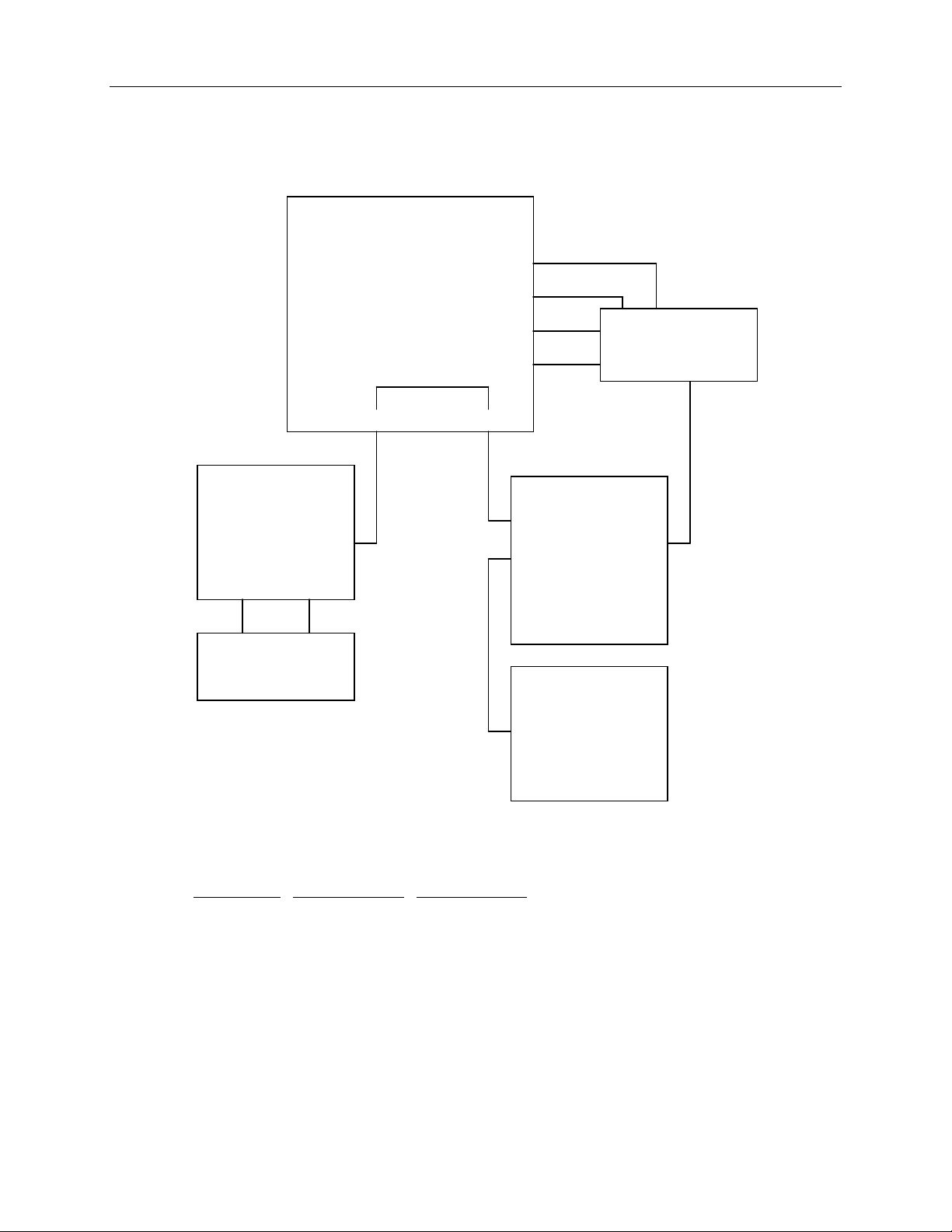
1 System Hardware Overview
This chapter provides a graphical overview of the InterServe 610, 620, 630, and 640 systems. The
“Major Assemblies” sections show relative locations of components such as power supplies,
peripherals, and boards. The “Functional Diagram Overview” sections provide an overview of the
power and data signal paths between the major assemblies. The table after each wiring diagram figure
leads you to pages in Chapter 2 for specific wiring diagrams, connector pinouts, and other information.
InterServe 610 (Non-RAID)
Major Assemblies
Disk Drive Bay
Power
Supply
1
Riser Card
Syst em Board
CD-ROM
Drive
Combo
Drive
Option
Board
Fans
P6 Bus
Termination
Card
Page 10

2
Functional Diagram Overview
AC In
CD-ROM Drive
Combo Drive
Processor Module
- or -
P6 Bus
Term i n at ion Card
Item Part Number
Fixed Power Supply MPWS131 19
CD-ROM Drive CDSK106 39
Combo Drive MESAM86 40
Fixed Disk Drives CDSK111, CDSK094,
Riser Card MSMT280 23
System Board MSMT313 27
Option Board Fans MCBLZ520,
System Disk Fan MCBLY690 43
Fixed Power
Supply
Riser
Card
System
Board
Memory
(SIMMs and
WRAM)
CDSK098, CDSK123
MCBLY690
Fixed Disk
Driv es
System Disk
Fan
Option Board
Fans
Chapter 2
Reference Page
41
43
Page 11

InterServe 610, 620 (Internal RAID)
Major Assemblies
Internal RAID
Section
Power
Supply
Power
Distribution
Board
3
CD-ROM
Drive
Combo
Drive
Riser Card
System Boa r d
RAID
Controller
Option
Board
Fans
P6 Bus Termination
Card (Plugged onto
System Board)
Page 12

4
Functional Diagram Overview
PC Card
Modem
AC In
CD-ROM Drive
Combo Drive
Server Monitor
Card
Processor Module
- or -
P6 Bus
Term ination Card
Power
Distribution
Board
Riser
Card
System
Board
Memory
(SIMMs and
WRAM)
Fixed Power
Supply
Internal RAID
Section
RAID
Controller
Auxiliary
Fan
Option Board
Fans
Chapter 2
Item Part Number
Power Distribution
Board
Fixed Power Supply MPWS131 19
CD-ROM Drive CDSK106 39
Combo Drive MESAM86 40
Internal RAID Section MESAN15 36
Riser Card MSMT280 23
System Board MSMT313 27
Option Board Fans MCBLZ520,
Auxiliary Fan CFAN1110 43
MPCBD13 10
MCBLY690
Reference Page
43
Page 13

InterServe 630, 640
Major Assemblies
Redundant Power
Supplies
AC Section
5
Internal RAID
Section
CD-ROM
Drive
Combo
Drive
Power
Distribution
Board
Riser Card
Processor Module
System Board
Option
Board
Fans
RAID Controller
Board
Page 14

6
Functional Diagram Overview
AC In
AC Section
with Safety
PC Card
Modem
Interlock
CD-ROM Drive
Combo Dri ve
Serv er M onitor
Card
Processor Module
or P6 Bus
Termination Card
Power
Distribution
Board
Riser
Card
System
Board
Memory
(SIMMs and
WRAM)
Power
Supply
Power
Supply
Internal RAID
Section
RAID
Controll er
Option Board
Fans
Chapter 2
Item Part Number
Reference Page
AC Section MESAN14 7
Power Distribution Board MPCBD17 13
Redundant Power Supplies MPWS138 21
CD-ROM Drive CDSK106 39
Combo Drive MESAM86 40
Internal RAID Section MESAN15 36
Riser Card MSMT280 23
System Board MSMT313 27
Option Board Fans MCBLZ520,
43
MCBLY690
Page 15

2 System Wiring Diagrams
AC Section (MESAN14)
AC Section - MESAN14
Power Supply
Keylock Switch
Power
Distribution
Board J2
7
AC In
NOTE The brown wires carry the AC line signal. The blue wires are neutral, and the green wires with yellow
stripe are safety ground.
AC Receptacle
- Line
- Ground
- Neutral
Circuit Br eaker
Power Supply
Keylock Switch
Alarm Si lence
Button
Top Cover
Safety Interl ock
Switch
Power
Distribution
Board J1
Power
Distribution
Board J17
Page 16

8
The following figure shows the top view of the AC section.
Keylock Switch
Alarm Silence Button
Power Supply
Cab le Opening
Circuit Breaker
Reset Switch
Keylock
Switch
To Safety
Interlock
Switch
Keylock Switch
The keylock switch performs two functions: it physically locks the power supply in the base unit (by
rotating a blade into a slot on the power supply), and engages an AC switch that provides power input
to each supply. The power supply will not come out of the base unit until the keylock switch is turned
to the OFF position.
Alarm Silence Button
The alarm silence button allows you to temporarily disable the alarm when it is sounding.
Power Cable to
MPCBD17 J2
Power Cable to
MPCBD17 J1
Page 17

Circuit Breaker
The circuit breaker contains an external button to indicate power fault status. When the button is
extended (white area showing), a fault has occurred. Do not reset the circuit breaker until after the fault
has been removed. Reset the circuit breaker by pressing the button.
Safety Interlock Switch
The safety interlock switch, located in the top of the base unit, prevents the system from powering on if
the top cover is not properly installed.
Power Cables
These two-wire cables provide the AC line and neutral signals to the power distribution board, which in
turn drives the power supplies.
Power Supply Cable Opening
The main power cable from the power distribution board to the riser card passes through this opening.
If servicing the AC section, be sure the plastic edging remains in the opening to protect the wires from
damage.
9
Page 18

10
Power Distribution Board (MPCBD13)
Power Distribut ion Board -
MPCBD13
Power On LED
Channel Mode LED
Auxiliary LED
RAID Section -
MESAN150
JP8
JP7
J2
Alarm Button
Power Supply
MPWS131 (P8)
MCBLZ610
MCBL060A
MCBL060A
MCBL057A
MCBL057A
MCBL055A
MCBL056A
J16
J40
J20
J18
J19
J13
J17
J10
MCBLZ610 -- MPCBD13 J16 to power on LED
Pin
Signal Wire Color
1 Pwrgood Black
2 Ground Black
MCBL060A -- MPCBD13 J40 to channel mode LED
Pin
Signal Wire Color
1 Dskbad Black
2 Ground Black
3 Dskgood Orange
Page 19

MCBL060A -- MPCBD13 J20, Auxiliary LED
11
Pin
1 Remote On/Off In
2 Remote On/Off Out
3 LED Ground
MCBL057A -- MPCBD13 J18 to MESAN150 JP8, drive installed
Pin
J18 - 1 Drive 1 Brown
J18 - 2 Drive 2 Black
J18 - 3 Drive 3 Red
MCBL057A -- MPCBD13 J19 to MESAN150 JP7, drive installed
Pin
J19 - 1 Drive 4 Brown
J19 - 2 Drive 5 Black
J19 - 3 Drive 6 Red
MCBL055A -- MPCBD13 J13 to MESAN150 J2, RAID sensor
Pin
1,2,3,4 +5.1V 26 Alarm Reset
6 Dskbad 30 Drive 1 Status
8 Dskgood 32 Drive 2 Status
10 Alarm 34 Drive 3 Status
12,14,28 No Connect 36 Drive 4 Status
16 Pwrbad 38 Drive 5 Status
22 Not used 40 Drive 6 Status
24 Not used Remaining Ground
Signal
Signal Wire Color
Signal Wire Color
Signal Pin Signal
MCBL056A -- MPCBD13 J17 to alarm
Pin
1 Alarm reset Red
2 Ground Black
Signal Wire Color
Page 20

12
The following figure shows the connectors on the power distribution board.
J10
J19
J13
J18
J20
J17 J40
J16
Page 21

Power Distribution Board (MPCBD17)
Side 1
Power Distribut ion Board -
MPCBD17
Side 1
Power On Switch
Power On LED
Channel Mode LED
MCBL079A
MCBL080A
J12
J16
13
RAID Subsystem -
MESAN150
JP8
JP7
J12
CD-ROM Driv e
Combo Drive
ISM Board -
CINF029
J6
J3
J9
MCBL077A
MCBL050A
MCBL050A
MCBL055A
MCBL049A
MCBL078A
J19
J3
J9
J13
J11
J41
MCBL079A -- MPCBD17 J12 to power on switch
Pin
Signal Wire Color
1 Power Switch On Red
2 Ground Black
3 Power On Reset Brown
Page 22

14
MCBL080A -- MPCBD17 J16 to power on LED and channel mode LED
Pin
1 Pwrgood Black
2 Ground Black
3 Pwrbad White
4 Dskbad Black
5 Ground Black
6 Dskgood Orange
MCBL077A -- MPCBD17 J19 to MESAN15 JP8/JP7, drive installed
Pin
1 Drive 1 Brown
2 Drive 2 Black
3 Drive 3 Red
4 Drive 4 Brown
5 Drive 5 Black
6 Drive 6 Red
MCBL050A -- MPCBD17 J3 to MESAN15 J12, RAID power
Pin
1 +12V Yellow
2 Ground Black
3 Ground Black
4 +5.1V Red
Signal Wire Color
Signal Wire Color
Signal Wire Color
MCBL050A -- MPCBD17 J9 to MESAN15 J6, RAID power
Pin
1 +12V Yellow
2 Ground Black
3 Ground Black
4 +5.1V Red
MCBL049A -- MPCBD17 J11 to CD-ROM Drive and Combo Drive, auxiliary power
Pin
1 +12V Yellow
2 Ground Black
3 Ground Black
4 +5.1V Red
Signal Wire Color
Signal Wire Color
Page 23

MCBL055A -- MPCBD17 J13 to MESAN15 J2, RAID sensor
15
Pin
Signal Pin Signal Pin Signal
1,2,3,4 +5.1V 22 Not used 34 Drive 3 Status
6 Dskbad 24 Not used 36 Drive 4 Status
8 Dskgood 26 Alarm Reset 38 Drive 5 Status
10 Alarm 30 Drive 1 Status 40 Drive 6 Status
12,14,28 No Connect 32 Drive 2 Status Remaining Ground
16 Pwrbad
MCBL078A -- MPCBD17 J41 to CINF029 J9, Server Monitor
Pin
Signal
1 +3.3 V
2 Ground
3 No Connect
4 Remote Power Off
5 LPOK
6 Remote Reset
The following figure shows the connector layout of MPCBD17 side 1.
J12
J19 J41
J13
J11
J16
J3
J9
Page 24

16
Side 2
Power/Signal Distribution
Board - MPCBD17
Side 2
J6
J7
J8
J4
J1
J2
J17
J5
J15
Power
Supply 1
Power
Supply 2
MCBL048A
MCBL064A
AC Section -
MESAN140
Keylock Swit ch
Keylock Swit ch
Alarm Silence
Button
Riser Card
MSMT280
J3
System Board
MSMT313
J74
Connector J6:
Pin
1,3,5,8,10,12 +5.1V
2,4,6,7,9,11,14,16,18 Ground
13,15,17 +3.3V
Signal
Page 25

Connector J7
17
Pin
1AC
2 No Connect 8 AC_GND 14 No Connect
3 -5.1V 9 Fan_OK_115CS
4 -12V 10 +3.3V_CS 16 DC_OK_1
5 +12V 11 +12V_CS 17 AC_OK_1
6 Ground 12 +5.1V 18 RMT_ON_OFF
Connector J8
Pin
1,3,5,8,10,12 +5.1V
2,4,6,7,9,11,14,16,18 Ground
13,15,17 +3.3V
Connector J4
Pin
1AC_Line_2 7 No Connect 13 AC_Neutral_2
2 No Connect 8 AC_Ground 14 No Connect
3 -5.1V 9 Fan_OK_215CS
4 -12V 10 +3.3V_CS 16 DC_OK_1
5 +12V 11 +12V_CS 17 AC_OK_1
6 Ground 12 +5.1V 18 RMT_ON_OFF
Signal Pin Signal Pin Signal
_
Line_1 7 No Connect 13 AC_Neutral_1
_
Signal
Signal Pin Signal Pin Signal
_
RTN
RTN
Connector J1 to MESAN140 Keylock Switch 1
Pin
1AC
2 No Connect
3AC
Connector J2 to MESAN140 Keylock Switch 2
Pin
1AC
2 No Connect
3AC
Signal Wire Color
_
Neutral_2 Blue
_
Line_2 Brown
Signal Wire Color
_
Neutral_1 Blue
_
Line_1 Brown
Page 26

18
Connector J17 to MESAN140 Alarm Silence Button
Pin
Signal Wire Color
1 Alarm Reset Brown
2 No Connect Black
MCBL064A -- MPCBD17 J15 to MSMT313 J74, reset
Pin
Signal Wire Color
1 System Reset Brown
2 No Connect Black
MCBL048A -- MPCBD17 J5 to MSMT280 J3, main power
Pin
Signal Wire Color Pin Signal Wire Color
1 +3.3V Orange 13 +5V Red
2 +3.3V Orange 14 Ground Black
3 +3.3V Orange 15 Ground Black
4 Ground Black 16 +5V Red
5 Ground Black 17 Ground Black
6 Ground Black 18 -12V Blue
7 +3.3V Orange 19 +5V Red
8 +3.3V Orange 20 -5V Red
9 +5V Red 21 Ground Black
10 Ground Black 22 +12V Yellow
11 +5V Red 23 Ground Black
12 Ground Black 24 Power Good Green
NOTE The DC Power Good signal is a TTL-compatible signal that initiates an orderly start-up procedure under
normal input operating conditions. During power up, this signal should remain low (< 0.8 VDC) for at
least 100 ms after the +5.1 VDC output has reached its minimum sense level of 4.75 VDC. The signal
should then transition to high (> 2.4 VDC) to indicate a stable power source. The signal drives an LED
on the back of the power supply to indicate the status (green is good, off is no signal).
NOTE The AC Power Good signal is a TTL-compatible signal that transitions to high to indicate that the AC
input voltage is within the 90 - 132 VAC or 180 - 264 VAC range. The signal drives an LED on the back
of the power supply to indicate the status (green is good, off is no signal). Provided there is an AC
input, this signal must be available to report whether the outputs are non-functional or functional.
Page 27

The following figure shows the connector layout of MPCBD17 side 2.
19
J6
J7
J2
J15
J17
J5
Fixed Power Supply (MPWS131)
The power supply is a 539 watt autoranging supply, that switches between 90-132 VAC or 180-264
VAC, depending on the location. The input frequency is 47-63 Hz, single phase. At full load, the
power supply has a minimum efficiency of 65 percent.
J8
J4
J1
DC Output Specifications
The following table details the DC Output Specifications for the power supply.
Nominal Output
Voltages
Continuous Load
(Maximum.)
Continuous Load
(Minimum.)
Noise and Ripple
(PARD) (DC to
30 MHz)
Initial Setting
Tolerance
Regulation
Line/Load
1, 5
1,
1,
2, 5
2, 5
Output #1
4
+3.3
3, 4
48
Output #2 Output #3 Output #4 Output #5 Unit
+5.1
3, 4
76
4
+12.0
4
12
4
−
12.0
−
5.0
0.5 0.5 ADC
VDC
06000ADC
50 50 100 250 100 mVp-p
Max
±3% ±3% ±5% ±10% ±10%
±3% ±3% ±5% ±10% ±10%
Max
Max
Page 28

20
Overshoot
(Turn on/off)
Table notes:
1. Power supply meets or exceeds these specifications. For the noted specifications, the “Maximum”
values describe the smallest acceptable maximum load and the “Minimum” values describe the
largest acceptable minimum load.
2. These outputs are measured at the user end of an unloaded peripheral cable.
3. +3.3 V and +5.1 V will never draw over 400 Watts combined.
4. Any combination of +3.3 V, +5.1 V, and +12 V do not exceed their maximum or 539 watts of total
power.
5. The sum of Initial Setting Tolerance and Line/Load Regulation do not exceed 3% for the +3.3 V
and +5.1 V outputs, 5% for the +12 V output, and 10% for the negative output voltages.
Cable Connectors
Output #1 Output #2 Output #3 Output #4 Output #5 Unit
5% 5% 10% 10% 10% Max
The following table shows the cable connectors from the power supply that connect to the riser card
and to the devices in the server.
Connector
P1 Main Power (Riser Card)
P2 CD-ROM Drive
P3 Auxiliary Drive
P4 Auxiliary Drive (or internal RAID subsystem)
P5 Auxiliary Drive
P6 Auxiliary Drive (or internal RAID subsystem)
P7 Auxiliary Drive
P8 Auxiliary Drive
P9 Combo Drive
Device
P1 Riser Card Connector Pinout
Pin Signal Wire Color Pin Signal Wire Color
1 +3.3V Orange 13 +5V Red
2 +3.3V Orange 14 Ground Black
3 +3.3V Orange 15 Ground Black
4 Ground Black 16 +5V Red
5 Ground Black 17 Ground Black
6 Ground Black 18 -12V Blue
7 +3.3V Orange 19 +5V Red
Pin
Signal Wire Color Pin Signal Wire Color
Page 29

8 +3.3V Orange 20 -5V Red
9 +5V Red 21 Ground Black
10 Ground Black 22 +12V Yellow
11 +5V Red 23 Ground Black
12 Ground Black 24 Power
P2 - P8 Connector Pinout
Pin Signal Wire Color
1 +12V Yellow
2 Return Black
3 Return Black
4 +5V Red
P9 Connector Pinout
Pin Signal Wire Color
1 +5V Red
1 Return Black
1 Return Black
4 +12V Yellow
21
Green
Good
Redundant Power Supplies (MPWS138)
The InterServe 630 and 640 servers use redundant 550 watt current-sharing power supplies. Each
power supply has five outputs, is hot swappable, and is auto-ranging between 90 - 132 VAC and 180 264 VAC. The input frequency range for each power supply is 47 - 63 Hz, single phase. The power
supply has the following DC output specifications:
Nominal Output
Voltages
Continuous Load
(Maximum.)
Continuous Load
(Minimum.)
1, 3
1
1
Noise and Ripple
(PARD) (DC to
30 MHz)
Initial Setting
Tolerance
3
Output 1
4, 5
Output 2
+3.3 +5.1 +12.0 -12.0 -5.0 VDC
45 85 12 1 1 ADC
0.0 3.5 1.0 0.0 0.0 ADC
50 50 100 250 100 mVp-p
4, 5
Output 1
Output 2
3% 3% 5% 10% 10% Max
4, 5
Output 3 5Output 4 Output 5 Unit
4, 5
Output 3 5Output 4 Output 5 Unit
Max
Page 30

22
Regulation
Line/Load
Overshoot
2, 3
3% 3% 5% 10% 10% Max
< 5 < 5 < 10 < 10 < 10 Max
(Turn on/off)
Table notes:
1. The power supply meets or exceeds these specifications.
2. These outputs are measured at the user end of an unloaded peripheral cable.
3. The sum of the Initial Setting Tolerance and Line/Load Regulation does not exceed 3% for the
+3.3 V and +5.1 V outputs, 5% for the +12 V output, and 10% for the negative output voltages.
4. Any combination of +3.3 V or +5.1 V do not exceed their maximum or 450 watts of total power.
5. Any combination of +3.3 V, +5.1 V, or +12 V do not exceed their maximum or 550 watts of total
power.
Characteristics of the power supplies include the following:
u
Over-Current Protection is provided on +3.3 VDC and +5.1 VDC outputs. The Over-Current
Protection disables the DC outputs and keeps them disabled until AC is cycled.
u
Over-Voltage Protection is provided on +3.3 VDC and +5.1 VDC. The Over-Voltage Protection
disables the DC outputs when the output reaches 5.5 - 6.8 VDC for +5.1V DC or 3.7 - 4.4 VDC
for +3.3 VDC. The DC outputs remain disabled until AC is cycled.
u
The current is equally shared (within +10%) by the two power supplies at maximum load. If one
power supply fails, the remaining power supply takes over. +3.3 V, +5.1 V, +12 V, -5 V, and 12V power outputs have series-connected blocking diodes to prevent an output fault in one power
supply from pulling down the outputs of the other power supply.
u
If one of the power supplies fails, an LED in that power supply either goes out or changes from
green to amber, and the power on LED on the front of the base unit changes from green to amber.
Look at the back of the base unit to see which power supply failed.
u
If a power supply is not supplying all of its DC voltage output levels correctly, an audible alarm
sounds.
Page 31

Riser Card (MSMT280)
InterServe 610 (Non RAID)
Riser Card - MSMT280
Side 1 Side 2
23
Power Supply
MPWS131 (P1)
MCBLW870
External SCSI
Port
Refer to “Power Supply MPWS131” for the P1 power connector pinout.
Refer to “SCSI” in the “External Ports” section for the SCSI connector pinout.
J2
PCI Slots 1-6
J3
ISA Slots 1 - 4
J15
System Board -
MSMT313
Page 32

24
InterServe 610, 620 (Internal RAID)
J2
Power Supply
MPWS131 (P1)
Riser Card - MSMT280
Side 1 Side 2
PCI Slots 1-6
MCBLW870
External SCSI
Port
J3
ISA Slots 1 - 4
J15
System Board -
MSMT313
Refer to “Power Supply MPWS131” for the P1 power connector pinout.
Refer to “SCSI” in the “External Ports” section for the pinout of the SCSI connector.
Page 33

InterServe 630, 640
25
Riser Card - MSMT280
Side 1 Side 2
MCBL048A
J5
MPCBD17
MCBLW870
External SCSI
Port
J2
PCI Slots 1-6
J3
ISA Slots 1 - 4
J15
System Board -
MSMT313
Refer to the MCBL048A information in “Power Distribution Board MPCBD17” section for the pinout
of the power connector.
Refer to “SCSI” in the “External Ports” section for the pinout of the SCSI connector.
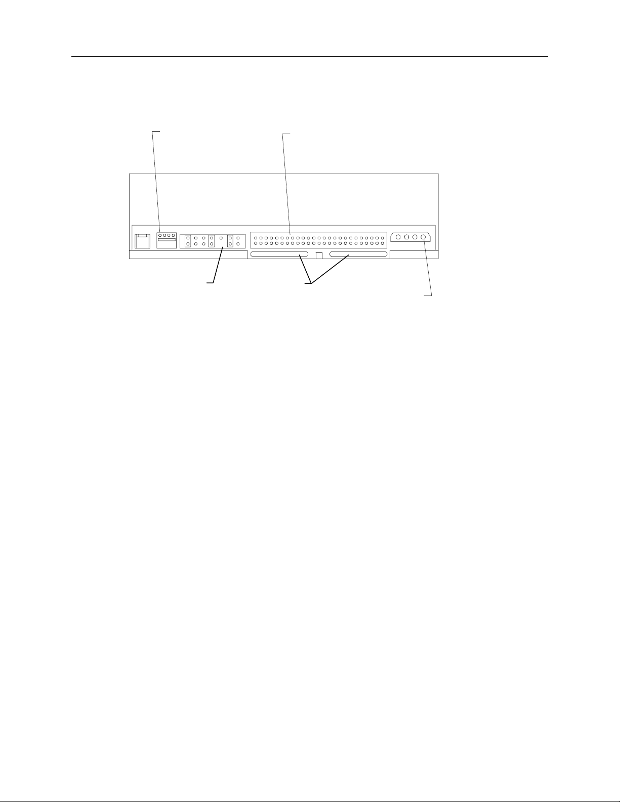
Page 34

26
The following figure shows the riser card used in all InterServe 610, 620, 630, and 640 servers.
PCI 1
PCI 2
PCI 3
PCI 4
PCI 5
PCI 6
ISA 1
ISA 2
ISA 3
J2
J3
Side 1
Side 2
ISA 4
Page 35

System Board (MSMT313)
J51 - J58
Cabling Diagram and Pinouts
Riser Card - MSMT280
27
Speaker
MSMT310
MSMT311
Primary (Boot)
MPCBD17
CD-ROM
Drive
MCBLY520
or
CPU
Secondary
CPU
MCBL064A
J15
MCBLZ220
MCBL066A
J71
J27/J23
J65
J66
J74
J22
J43
J15
System Board -
MSMT313
External Ports
J68
J32
J33
J30
J17
J11
MCBLZ530
Memory
SIMMs
MCBLZ370
MCBLZ370
MCBL067A
MCBL038A
MCBLZ180
MMSA365
J3
J6
J2
MESAM86
External MIDI
Port
External AUI
Port
MCBLZ180 -- MSMT313 J11 to Ethernet AUI Port
Pin
Signal Pin Signal Pin Signal
1 Ground 6 Ground 11 Ground
2 CI+ - Collision
7 Reserved 12 DI– - Data in
detect
3 DO+ - Data out 8 Ground 13 +12V - 12 volts
4 Ground 9 CI– - Collision detect 14 Ground
5 DI+ - Data in 10 DO– - Data out 15 Reserved
Page 36

28
MCBL038A -- MSMT313 J17 to MIDI Port, MIDI
Pin
1 +5V 6 Y-axis, joystick 1 11 X-axis, joystick 2
2 Fire button 0 7 Fire button 1 12 MIDI out
3 X-axis, joystick 1 8 +5V 13 Y-axis, joystick 2
4 Ground 9 +5V 14 Fire button 3
5 Ground 10 Fire button 2 15 MIDI in
MCBLZ220 -- MSMT313 J22 to CD-ROM drive, audio
Pin
1 Right Channel Red
2 Ground Black
3 Left Channel White
4 Ground Black
MCBL067A -- MSMT313 J30 to Combo Drive J2, floppy disk drive
Pin
2 RPM 14 DRV0- 26 TRK04 No connect 16 MTR1- 28 WRPRT6 DRATE0 18 DIR 30 RDATA8 INDEX- 20 STEP- 32 HDSEL
10 MTR0- 22 WDATA- 34 DSKCHG
12 DRV1- 24 WGATE- Odd Ground
Signal Pin Signal Pin Signal
Signal Wire Color
Signal Pin Signal Pin Signal
MCBLZ370 -- MSMT313 J32 to Combo drive J3, ISA bus
Pin
1 IRQ15 11 SD+(14) 21 SA+(17) 31 SA+(6)
2 IRQ14 12 SD+(15) 22 SA+(18) 32 SA+(7)
3 IRQ10 13 SD+(11) 23 SA+(21) 33 SA+(10)
4 IRQ3 14 SD+(10) 24 SA+(22) 34 SA+(11)
5 IRQ7 15 SD+(0) 25 SA+(1) 35 SA+(14)
6 IRQ9 16 SD+(1) 26 Ground 36 SA+(15)
7 IOCS16- 17 SD+(4) 27 SA+(3) 37 BALE
8 Ground 18 SD+(5) 28 Ground 38 IOR9 IOCHRDY+ 19 MEMW- 29 RSTDRV 39 D7BUFDIR
10 Ground 20 MEMR- 30 Ground 40 PWR_DWN
MCBLZ370 -- MSMT313 J33 to Combo drive J6, ISA bus
Signal Pin Signal Pin Signal Pin Signal
Page 37

29
Pin Signal Pin Signal Pin Signal Pin Signal
1 Spare 11 SD+(13) 21 SA+(23) 31 SA+(8)
2 IRQ11 12 SD+(12) 22 SBHE- 32 SA+(9)
3 IRQ4 13 SD+(9) 23 SA+(0) 33 SA+(12)
4 IRQ5 14 SD+(8) 24 Ground 34 SA+(13)
5 0WS- 15 SD+(2) 25 SA+(2) 35 SA+(16)
6 Ground 16 SD+(3) 26 Ground 36 AEN
7 MEMCS16- 17 SD+(6) 27 ISA BCLK 37 IOW8 Ground 18 SD+(7) 28 Ground 38 Ground
9 SPKR- 19 SA+(19) 29 SA+(4) 39 LOBUFDIR
10 Ground 20 SA+(20) 30 SA+(5) 40 HIBUFDIR
The following figure shows the MSMT313 cable connectors.
J22
J11
J17
J43
J32
J33
J30
J27
J23
J71
J74
J68
Page 38

30
Jumper Connectors
The following figure shows the MSMT313 jumper connectors.
Vibra 16S Sound
Disable/Enable
CPU Frequency
(Primary CPU)
CPU Frequency
(Secondary CPU)
G95 VGA Mode
Disable/Enable
CPU Frequency
Primary CPU
Jumper 150 MHz
(5/2x)
200 MHz
(3x)
Secondary CPU
Jumper 150 MHz
(5/2x)
200 MHz
(3x)
J60 IN IN J47 IN IN
J61 OUT IN J48 IN OUT
J62 IN IN J49 IN IN
J63 IN OUT J50 OUT IN
CAUTION Do not change the jumper settings in an attempt to change CPU speed. The CPUs will only operate
properly when the jumpers are installed in their default settings.
The following figure shows the detail of the CPU frequency jumper connectors.
Page 39

31
CPU
VRM
J63
J62
J61
J60
J49
J50
J48
J47
CPU
Jumpers for
Primary CPU
Jumpers for
Secondary CPU
G95 VGA Mode Disable/Enable - J26
Off (default) = VGA mode enabled
On = VGA mode disabled
You must remove the PCI option boards and MSMT310 (or MSMT311) to access J26.
Vibra 16S Sound Disable/Enable - J24
On (Pins 2-3) (default) = Sound enabled
Off (Pins 1-2) = Sound disabled
You must remove the ISA option boards to access J24.
Page 40

32
External Ports
The following figures show the external ports in their proper orientation, when the base unit is in the
upright position.
MIDI
15
9
Ethernet 10Base-T
1
8
1
8
Pin
Signal Pin Signal
1 +5V 9 +5V
2 Fire button 0 10 Fire button 2
3 X-axis, joystick 1 11 X-axis, joystick 2
4 Ground 12 MIDI out
5 Ground 13 Y-axis, joystick 2
6 Y-axis, joystick 1 14 Fire button 3
7 Fire button 1 15 MIDI in
8 +5V
Pin
Signal Pin Signal
1 TD+ - Transmit 5 Reserved
2 TD– - Transmit 6 RD– - Receive
3 RD+ - Receive 7 Reserved
4 Reserved 8 Reserved
Page 41

Serial (COM)
33
6
9
Ethernet AUI
9
5
1
5
1
8
Pin
1 DCD - Data Carrier Detect
2 RD - Receive Data
3 TD - Transmit Data
4 DTR - Data Terminal Ready
5 Ground
6 DSR - Data Set Ready
7 RTS - Request to Send
8 CTS - Clear to Send
9 RI - Ring Indicator
Signal
Pin
1 Ground
2 CI+ - Collision detect
3 DO+ - Data out
4 Ground
5 DI+ - Data in
6 Ground
7 Reserved
8 Ground
9 CI– - Collision detect
10 DO– - Data out
11 Ground
12 DI– - Data in
13 +12V - 12 volts
14 Ground
15 Reserved
Signal
WARNING Do not connect a MIDI cable to the AUI
connector. This will short out the local area network on which the system resides.
Page 42

34
SCSI
50
26
25
1
Pin
26 Command Data-0
27 Command Data-1
28 Command Data-2
29 Command Data-3
30 Command Data-4
31 Command Data-5
32 Command Data-6
33 Command Data-7
34 Command Data Parity
38 Terminator Power
41 Attention
43 Busy
44 Acknowledge
45 Reset
46 Message
47 Select
48 Command
49 Request
50 Input/Output
Signal
Note Pins 12, 13, 14, 37, and 39 are not connected; all
other pins not listed are connected to ground.
Mouse and Keyboard
2 4 6
Mouse
Pin Signal Pin Signal
1 MDATA 1 KDATA
2 Reserved 2 Reserved
3 Ground 3 Ground
4 Fused VCC -
5 MCLK 5 KCLK
1 3 5
6 Reserved 6 Reserved
+5V
Keyboard
4 Fused VCC -
+5V
Page 43

Parallel
35
14
25
5 10 15
1 6 11
1
13
Pin
Signal Pin Signal
1 -Strobe 10 -ACK -
Acknowledge
2 Data 0 11 Busy
3 Data 1 12 PE - Paper Empty
4 Data 2 13 +Select
5 Data 3 14 -Auto FDXT -
Auto Feed
6 Data 4 15 -Error
7 Data 5 16 -Init - Start
8 Data 6 17 -SLCTIN - Select
9 Data 7 18-25 Ground
Video
Pin
Signal
1 R - Red
2 G - Green
3 B - Blue
4 MID2 - Monitor ID2
5, 6, 7, 8, 10 Ground
9 No Connect
11 MID0 - Monitor ID0
12 MID1 - Monitor ID1
13 HSYNC - Horizontal Sync
14 VSYNC - Vertical Sync
15 MID3 - Monitor ID3
Page 44
36
Internal RAID Section (MESAN15)
RAID Section - MESAN15
(MSMT323)
J12
J6
J5 J11
RAID Control ler
Board - CINF026
CHN2
CHN1 CHN0
To External Disk
Arrays
MCBL054A
MCBL061A
MCBL061A
JP8
JP7
J2
J1
J1
Power Distribution
Board
J13
MCBL055A
MESAN15
(MSMT321)
J3
Slot 4 LED
Slot 5 LED
Slot 6 LED
MESAN15
(MSMT322)
Slot 3 LED
Slot 2 LED
Slot 1 LED
The following table shows the cables used with the RAID section with either power distribution board.
Refer to the appropriate power distribution board section for the following cable pinouts.
MESAN150
J12
J6
JP8
JP7
MPCBD13 MPCBD17
MPWS131 MCBL050A J3
MPWS131 MCBL050A J9
MCBL057A J18 MCBL077A J18
MCBL057A J19 MCBL077A J19
Page 45

MCBL054A -- MESAN150 J5 to CINF026 CHN 2
37
Pin
1-16 Ground 50 Shell OK (Ground)
17 Term Power 51 Term Power
18 Term Power 52 Term Power
19 No Connect 53 No Connect
20-34 Ground 54 Fault Clock (Ground)
35 SCSI Data Bit 12 55 Attention
36 SCSI Data Bit 13 56 Fault Data
37 SCSI Data Bit 14 57 Busy
38 SCSI Data Bit 15 58 Acknowledge
39 SCSI Data Parity 1 59 Reset
40 SCSI Data Bit 0 60 Message
41 SCSI Data Bit 1 61 Select
42 SCSI Data Bit 2 62 Carrier Detect
43 SCSI Data Bit 3 63 Request
44 SCSI Data Bit 4 64 I/O
45 SCSI Data Bit 5 65 SCSI Data Bit 8
46 SCSI Data Bit 6 66 SCSI Data Bit 9
47 SCSI Data Bit 7 67 SCSI Data Bit 10
48 SCSI Data Parity 0 68 SCSI Data Bit 11
49 SWAP (Ground)
Signal Pin Signal
Page 46

38
The following figure shows the cable connections to the internal RAID section, MESAN15.
J6
J12
J11
JP8
J2
J3
J1
J1
J5
JP7
Page 47
CD-ROM Drive (CDSK106)
39
Audio Connector
(MCBLZ22Ato
MSMT313 J22)
Mode Select
Header
Settings for mode select header are printed on the CD-ROM drive.
Teminators should be removed. SCSI termination is provided by the SCSI cable.
Refer to “External Ports” for SCSI pinout.
Refer to “System Board MSMT313” for audio pinout. If the Panasonic CD-ROM drive is installed, the
sound cable is MCBLZ64.
Terminat or
Sockets
SCSI Connector
(MCBL066A to
MSMT313 J43)
Power Con nector
Refer to the appropriate section as listed below for the power cable pinout.
InterServe 610, 620 (Non RAID) - “Fixed Power Supply MPWS131”
InterServe 610, 20 (Internal RAID) - “Fixed Power Supply MPWS131”
InterServe 630, 640 - “Power Distribution Board MPCBD17” Table MCBL049A
Page 48

40
Combo Drive (MESAM86)
Power
Connector
Converter
Connector
J5 J4
J6 J3
J3 ISA Bus Connector
(MCBLZ37A to MSMT313 J32)
J6 ISA Bus Connector
(MCBLZ37A to MSMT313 J33)
Floppy Connector
(MCBL067A to MSMT313 J30)
(MCBLZ230 to J4)
J2
Refer to “System Board” for Floppy, ISA Bus J3, and ISA bus J6 pinouts.
Refer to the appropriate section for combo drive power cable pinout.
InterServe 610, 620 (Non RAID) - “Fixed Power Supply MPWS131”
InterServe 610, 20 (Internal RAID) - “Fixed Power Supply MPWS131”
InterServe 630, 640 - “Power Distribution Board MPCBD17” Table MCBL049A
Page 49

Fixed Disk Drives
The following disk drives are used in the InterServe 610 systems, without internal RAID.
41
Part Number
CDSK111 SeagateST51080N 1 GB
CDSK094 Seagate ST32155N 2 GB
CDSK098 Conner CFP4207S 4 GB
CDSK123 Seagate ST34371N 4 GB
SCSI ID selection is defined in the following table. Each disk drive has a connector which uses
jumpers to set the SCSI ID. Where Seagate uses ID1, ID2, and ID4 to identify how to set the SCSI ID,
Conner uses 0E1, 0E2, and 0E3.
SCSI ID
0 Off Off Off
1 On Off Off
2 Off On Off
3 On On Off
4 Off Off On
5 On Off On
6 Off On On
CDSK111 1 GB
The following figure shows the jumper connector J8 on the back of the disk drive.
Vendor Number Capacity
ID1/0E1 ID2/0E2 ID4/0E3
ID1
ID2
ID4
Pin 2
Pin 1
SCSI ID selection uses the ID1, ID2, and ID4 jumpers on connector J8. To disable SCSI termination,
install the Term Disable jumper and remove both Term Power jumpers from connector J8. To enable
SCSI termination, remove the Term Disable jumper and install both Term Power jumpers onto J8.
ooooooo oooooooooo
ooooooooooooooooo
Parity
Enable
Term
Disable
J8
Term Power
Page 50

42
CDSK094 2 GB
The following figure shows the jumper connectors J6 and J2 on the disk drive.
ID1
ID2
ID4
J6
TE
J2
oooooooo
oooooooo
SCSI
Connector
Pin 1
Power
Connector
TP
SCSI ID selection uses the ID1, ID2, and ID4 jumpers on connector J6. To disable SCSI termination,
remove the TE jumper from connector J2.
CDSK098 4 GB
The following figure shows the jumper connector J5 and SCSI terminator sockets on the disk drive.
0E1
0E2
0E3
SCSI Termin ator
Sockets
J5
Connectors 0E1 through 0E3 are also available on a jumper block near the SCSI terminator sockets; do
not install jumpers on these connectors. To enable SCSI termination, install the proper resistors into
both terminator sockets. To disable SCSI termination, remove both resistors from the sockets.
Page 51

CDSK123 4 GB
The following figure shows the jumper connectors J6 and J2 on the disk drive.
43
ID1
ID2
ID4
SCSI ID selection uses the ID1, ID2, and ID4 jumpers on connector J6. To disable SCSI termination,
remove the TE jumper from connector J2.
J6
Option Board Fans
TE
J2
oooooooo
oooooooo
SCSI
Connector
Pin 1
Power
Connector
The option board fans are one 119 mm (MCBLZ520) and two 80 mm (MCBLY690), attached to
MMSA3650. The fan power cable MCBLZ530 connects the fans to J68 on MSMT313. All InterServe
systems use these fans.
Auxiliary Fan (CFAN1110)
Only InterServe 610 and 620 systems with RAID use CFAN1110, located under the power supply.
CFAN1110 is a 92 mm fan mounted to CFAB303F. The fan power cable connects to J12 on
MSMT313. CFAN1100, fan guard, is installed over the opening in CFAB304F, power supply access
panel. InterServe 610 systems without RAID do not use CFAN1110.
System Disk Fan (MCBLY690)
Only non-RAID InterServe 610 systems use MCBLY690, an 80 mm fan mounted to CFAB304F,
power supply access panel. MCBLZ660 is used to connect MCBLY690 to J12 on MSMT313.
InterServe 610 and 620 systems with RAID do not use MCBLY690 attached to CFAB304F.
Page 52

44
Page 53

3 Accessing the System
This section describes opening the system base unit to gain access to various field replaceable and
upgradeable parts.
45
To Service
Internal SCSI drives Top cover, both side panels 53
Combo drive MESAM86 Top cover, both side panels 55
Internal RAID Section MESAN150 Top cover, both side panels 56
Riser card MSMT280 Top cover, left side panel, PCI access panel,
Processor module MSMT310 Top cover, left side panel, PCI access panel 58
P6 bus termination card MSMT311 Top cover, left side panel, PCI access panel 59
System board MSMT313 Top cover, left side panel, PCI access panel,
Fixed Power Supply MPWS131 Top cover 62
Redundant Power Supply MPWS138 n/a 63
AC section MESAN140 Top cover, both side panels 64
Power distribution board MPCBD13 Top cover, left side panels 66
Power distribution board MPCBD17 Top cover, both side panels 66
InterSite Server Monitor CINF029 Top cover, left side panel 67
SIMMs FMEM13X Top cover, left side panel, PCI access panel,
Option board fan assembly Top cover, left side panel, option board
System Drive Fan MCBLY690 Top cover 71
Auxiliary fan CFAN1110 Top cover, power supply access panel 72
Remove Page
58
riser card brace
60
option board bracket
68
PCI board guide
70
bracket
To Upgrade
Processors Top cover, left side panel 73
Memory Top cover, left side panel, PCI access panel,
Internal SCSI drives Top cover, both side panels 77
Option Boards Top cover, left side panel, PCI access panel 79
Remove Page
75
PCI board guide
Page 54

46
Precautions
Before servicing or upgrading the system, heed the following:
WARNING Leave the AC power cord from the InterServe 610 and 620 base unit connected to the AC wall
outlet to maintain safety ground. If the AC power cord is disconnected, you could be injured or
cause damage to the system.
WARNING Hazardous voltages exist inside the InterServe 630 and 640 base unit. Disconnect the AC power
cord from the base unit before servicing or upgrading the system. If the AC power cord remains
connected, you could be injured or cause damage to the system.
CAUTION The parts inside the base unit are designed to fit within very tight tolerances; some force is required to
remove or insert parts. However, if you cannot remove or install a part properly, ensure that there are
no obstructions hindering the part.
Top Cover and Side Panels
CAUTION Use caution when removing covers and panels to avoid injury.
NOTE The left and right side panels are identified when facing the front of the base unit.
1. Shut the system down; then turn the system power off.
2. Disconnect the AC power cord.
3. Remove the stabilizer feet.
4. Remove the screw on the back of the top cover; then pull the top cover back an inch and lift it off
the base unit.
5. Remove the two screws at the top of each side panel; then pull the side panels up and away from
the base unit. Refer to the following figure.
Page 55

47
Right Side
Panel Screws
Left Side
Panel Screws
Top Cover
Power Supply Access Panel
NOTE Only InterServe 610 and 620 systems use the power supply access panel.
To remove the power supply access panel:
1. Remove the screws from around the power supply access panel as shown in the following figure.
Page 56

48
Screws
Screws
Power Supply
Access Panel
2. Slide the power supply access panel to the right and pull it out of the base unit.
PCI Access Panel
To remove the PCI access panel:
1. Remove the top cover and left side panel.
2. Lay the base unit on its right side.
3. Remove the two screws at the bottom of the unit and the screw behind the PCI access panel.
4. Slide the PCI access panel to the back of the base unit. Refer to the following figure.
Page 57

Screws
49
Screw (Behind
Panel)
PCI Access
Panel
Riser Card Brace and PCI Board Guide
To remove the riser card brace:
1. Remove the PCI access panel.
2. Remove the RAID controller and other installed PCI option boards. Note the position of each PCI
board. After servicing, you must replace each board into the same slot from which you removed it.
3. Remove the ISA I/O lock bracket as shown in the following figure.
Riser Card
Brace
ISA I/O Lock
Bracket
Riser Card
Page 58

50
4. Remove the screw for the PCI board guide, and remove the board guide as shown in the following
figure.
5. Loosen the screw and pivot the ISA board guide toward the fan assembly as shown in the
following figure.
PCI Board
Guide
Screw
Screw
ISA Board
Guide
6. Note the position of and remove each ISA board. After servicing, you must replace each board
into the same slot from which you removed it.
Page 59

7. Remove the screws as shown in the following figure. Slide the riser card brace to the back of the
base unit and remove the bracket.
Riser Card
Brace
51
Protecting Against Electrostatic Discharge
Sensitive components inside the base unit can be damaged by static electricity. To protect against this
possibility, take the following precautions when working with the internal components of the system.
u
Do not service the system on surfaces known to have high electrostatic buildup, such as rugs and
carpets. Work on a static-safe surface instead.
u
Touch the bare metal of the base unit to ensure the base unit and your body are at the same electric
potential.
u
Handle all printed circuit boards as little as possible and by the edges only. Leave new parts in
their protective packaging until you install them.
u
Use a disposable or re-usable antistatic wrist strap when servicing or upgrading the system. A
disposable wrist strap can only be used once.
Page 60

52
u
A re-usable antistatic wrist strap can be attached to the ground loop above the ISA slots, as shown
in the following figure, or to any other bare metal part of the base unit. The metal conductor bead
in the elastic sleeve of re-usable antistatic straps must contact bare skin.
Ground Loop
Closing the System
CAUTION After servicing or upgrading the system, always replace the panels and covers that were removed. The
panels and covers ensure the system maintains proper air flow, so internal components do not
overheat, causing failure. The panels and covers also ensure that electromagnetic interference (EMI)
emissions remain below the standard requirements.
NOTE When securing panels with screws, ensure the screws are tight, but do not strip the screw heads.
To close the system:
1. Remove the antistatic wrist strap from the base unit.
2. Replace the PCI access panel if removed.
3. Set the base unit in the upright position.
4. Replace the left and right side panels if removed.
5. Replace the top cover if removed. Ensure the top cover is completely installed so the safety
interlock switch engages. If the cover is not properly installed, the system will not start.
6. Replace the stabilizer feet.
7. Restart the system.
Page 61

53
4 Servicing System Parts
Open the base unit and heed the antistatic precautions as described in Chapter3, “Accessing the
System.” After servicing, close the base unit as also described in Chapter3.
WARNING Leave the AC power cord from the InterServe 610 and 620 base unit connected to the AC wall
outlet to maintain safety ground. If the AC power cord is disconnected, you could be injured or
cause damage to the system.
WARNING Hazardous voltages exist inside the InterServe 630 and 640 base unit. Disconnect the AC power
cord from the base unit before servicing the system. If the AC power cord remains connected,
you could be injured or cause damage to the system.
CAUTION The parts inside the base unit are designed to fit within very tight tolerances; some force is required to
remove or insert parts. However, if you cannot remove or install a part properly, ensure that there are
no obstructions hindering the part.
Internal SCSI Drives
This section applies to CD-ROM drive, fixed disk drives, and tape drives.
To replace an internal SCSI drive:
1. Open the base unit and remove the necessary parts as described in Chapter 3.
2. Disconnect the power cable and SCSI cable from the drive. If removing the CD-ROM drive, also
remove the audio cable. Refer to the following figure.
Page 62

54
CD-ROM
Drive
Audio
Cable
Disk
Drive
Screws
Power Cable
SCSI Cable
3. Remove the screws from both sides of the SCSI drive.
4. Slide the SCSI drive out of the front of the base unit.
5. If replacing a disk drive (located above the CD-ROM drive), remove the bracket from the drive.
Refer to the following figure.
Screw
Slide
Bracket
6. Disable SCSI termination and set the SCSI ID on the back of the drive to the same ID as the drive
being replaced. If necessary, refer to the documentation delivered with the SCSI drive for
instructions.
7. If installing a hard disk drive, attach the drive to the bracket.
8. Insert the new SCSI drive through the front panel.
9. Secure the SCSI drive using the screws removed previously.
Page 63

55
10. Connect the SCSI cable, power cable, and audio cable (CD-ROM drive only). The SCSI cable red
stripe (pin 1) must be adjacent to the power connector.
Note: If installing a non-Intergraph CD-ROM drive, use the audio cable delivered with the new CD-ROM drive.
11. Close the base unit.
Combo Drive (MESAM86)
To replace the combo drive:
1. Open the base unit and remove the necessary parts as described in Chapter 3.
2. Remove the CD-ROM drive as described in “Internal SCSI Drives” page 53.
3. Using a quarter-inch nutdriver, remove the screws from both sides of the combo drive as shown in
the following figure. Then slide the drive out of the base unit.
Red
Stripe
Screws
Floppy Cable
ISA Bus
Cables
Power Cable
4. Disconnect the floppy cable, ISA bus cables, and power cable from the combo drive. Note the
position of the red stripe on the floppy cable and ISA bus cables.
5. Remove the four screws from the support bracket as shown in the following figure.
Red Stripe
Page 64
56
Support
Bracket
Screws
6. Secure the replacement drive to the support bracket using the screws removed previously.
7. Connect the cables to the combo drive.
8. Install the drive into the base unit, and secure it using the screws removed previously.
9. Replace the CD-ROM drive and secure it to the chassis. Connect the cables to the drive.
10. Close the base unit.
Internal RAID Section (MESAN15)
To replace the internal RAID section:
1. Open the base unit and remove the necessary parts as described in Chapter 3.
2. Remove the CD-ROM drive as described in “Internal SCSI Drives.” Support the drive as you
remove it.
3. Remove the RAID disk drives from the slots and place the drives onto a flat antistatic surface.
4. Disconnect the cables (except the sensor cable) attached to the internal RAID subsystem. Refer to
the following figure.
5. Remove the four screws from the top, and the two screws on either side, of the RAID subsystem.
Refer to the following figure.
Page 65

Power
Cables
57
Screws (4)
Screw s (2
each side)
Sensor
Cable
RAID SCSI
Cable Drive Installed
Cable
6. Slide the RAID subsystem out of the base unit. Disconnect the sensor cable.
7. Connect the sensor cable to the new RAID subsystem. Slide the subsystem into the base unit.
8. Replace the eight screws removed previously.
9. Reconnect the internal cables.
NOTE The cable attached to J19 on the power distribution board connects to JP7 on the RAID subsystem,
and the cable attached to J18 connects to JP8. The P6 power cable attaches to connector J12 on the
RAID subsystem, and the P4 power cable attaches to J6.
7. Replace the CD-ROM drive and reconnect its cables.
8. Close the base unit.
9. Install the RAID disk drives into the proper slots.
Page 66

58
Riser Card (MSMT280)
To replace the riser card:
1. Open the base unit and remove the necessary parts as described in Chapter 3.
2. Disconnect the SCSI cable and main power cable from the top of the riser card.
3. Disengage the riser card from its system board slot, and remove the card from the base unit.
4. Insert the new riser card into its system board slot, pushing firmly over the center of the PCI
connectors.
CAUTION Do not rock the riser card back and forth; pins inside the connector may be damaged as a result.
Press firmly so the card connector slides evenly into the slot.
5. Replace the option board bracket. Do not tighten the pivoting ISA board guide until the ISA
boards have been installed.
6. Replace the option boards connected to the riser card. Connect any external cables attached to the
boards. Replace the option boards in the same slots from which you removed them.
7. Replace the ISA I/O lock bracket and PCI access panel.
8. Connect the SCSI and power cables to the riser card.
9. Close the base unit.
Processor Module (MSMT310)
The module contains two CPUs and a Voltage Regulator Module (VRM) for each CPU.
To replace the processor module:
1. Open the base unit and remove the necessary parts as described in Chapter 3.
2. Lay the base unit on its right side.
3. Remove the installed PCI option boards.
4. Remove the screws from the perimeter of the processor module. Refer to the following figure.
Page 67

59
Processor
Module
6. Disengage the processor module from the system board connectors.
7. Align the new processor module over the connectors and firmly press it onto the connectors.
8. Secure the module using the screws removed previously.
9. Replace the option boards in the same slots from which you removed them.
10. Close the base unit.
P6 Bus Termination Card (MSMT311)
To replace the P6 bus termination card:
1. Open the base unit and remove the necessary parts as described in Chapter 3.
2. Ensure the AC power cable is disconnected and the antistatic strap is properly connected.
3. Lay the system on its right side.
4. Remove the installed PCI option boards.
5. Remove the screws that secure the termination card to the system board.
Page 68

60
P6 Bus Termination
Card
6. Carefully disengage the termination card from the connectors.
7. Install the new termination card. The connectors are keyed to ensure proper orientation. Carefully
but firmly push the termination card into the connectors.
8. Secure the termination card with the screws removed previously.
9. Replace the option boards in the same slots from which you removed them.
10. Close the base unit.
System Board (MSMT313)
CAUTION The system board is extremely sensitive to static electricity. To prevent serious damage to the system
board, wear the antistatic wrist strap while performing the following steps. Do not open the antistatic
bag containing the system board until instructed.
NOTE Before opening the base unit, run the AMIBIOS Setup program and record all the custom settings for
your system. After replacing the system board, you must run the System Configuration Utility for the
ISA boards. Ensure you have the necessary ISA board configuration files on diskette before you begin.
To replace the system board:
1. Open the base unit and remove the necessary parts as described in Chapter 3.
2. Ensure the AC power cable is disconnected and the antistatic strap is properly connected.
3. Remove the riser card as described in “Riser Card MSMT280” on page 58.
4. Remove the processor module as described in “Processor Module MSMT310” (on page 58)or the
P6 bus termination card as described in “P6 Bus Termination Card MSMT311” (on page 59).
5. Remove the option board fan assembly as described in “Option Board Fan Assembly MMSA356”
on page 69.
Page 69

6. Disconnect all cables attached to the system board. Refer to the following figure for cable
connector locations.
Internal SCSI
Speaker
Reset
Audio
MIDI
Fan
Assembly
Power
Ethernet
AUI
Floppy Cable
Connector
ISA Bus
61
7. Disconnect the cables from the external ports.
8. Using a three-sixteenth-inch nutdriver, remove the jackscrews from the video, parallel, and serial
ports.
9. Using an 8 mm or five-sixteenth-inch nutdriver, remove the hex nuts from the audio jacks.
Audio
Jacks
Serial Parallel Video
Ports Port Port
10. Using a quarter-inch nutdriver, remove the eight grounding screws from the system board.
Page 70

62
11. Slide the system board to the front of the base unit.
12. Lift the board and remove it from the base unit. Set the board on a flat antistatic surface.
13. Remove the new system board from the antistatic bag and place it on a flat antistatic surface.
14. Remove the SIMMs from the old system board and install them onto the new system board in the
same configuration.
15. Remove the G95 WRAM module, if installed, and install it onto the new system board.
16. Lower the system board into the base unit. Ensure the standoffs line up with the holes in the
chassis. Slide the system board so the external ports fit into the back panel.
17. Install the jackscrews onto the video, parallel, and serial ports.
18. Install the hex nuts onto the line out, line in, and microphone ports.
19. Install the eight ground screws.
20. Install the processor module (or P6 bus termination card).
21. Connect the game, audio, and Ethernet AUI cables to the system board.
CAUTION Do not connect a MIDI or game cable to the Ethernet AUI port. This could short out the local area
network on which the system resides.
22. Replace the option board fan assembly.
23. Replace the riser card, option board bracket, option boards, and SCSI and power cables.
24. Replace the PCI access panel.
25. Connect the external system cables to the external ports.
26. Close the base unit.
27. Run the AMIBIOS Setup utility and change the parameters to your required settings. Refer to the
System Setup.
28. If you have ISA option boards installed, run the System Configuration Utility. Refer to the System
Setup.
Fixed Power Supply (MPWS131)
CAUTION Replacement power supplies should be purchased from Intergraph to ensure proper specifications are
met and to guarantee safety.
To replace the power supply:
1. Open the base unit and remove the necessary parts as described in Chapter 3.
2. Disconnect the power cables from the riser card, hard disk drives (or internal RAID subsystem and
DC distribution board), CD-ROM drive, and combo drive.
3. Using a quarter-inch nutdriver, remove the screws securing the power supply to the back of the
base unit. Refer to the following figure.
Page 71

Screws
63
CAUTION Support the power supply with your hand as you remove the screws. Otherwise, the power supply will
fall onto the system hard disk drive or RAID disk drives fan assembly.
4. Push the power supply out the side of the base unit.
5. Place the new power supply in the base unit and slide the power cable bundle through the opening.
Connect the main power cable to the riser card.
6. Connect the remaining power cables to the hard disk drives (or internal RAID subsystem and DC
distribution board), CD-ROM drive, and combo drive.
7. Secure the power supply to the base unit using the screws removed previously.
8. Connect the AC power cord.
9. Close the base unit.
Redundant Power Supply (MPWS138)
To replace a redundant power supply:
1. Turn the keylock to the OFF position on the power supply being replaced. Refer to the following
figure.
2. Disengage the power supply by pulling the release lever. Refer to the following figure.
Page 72

64
Release Lever
Keylock
3. Install the new power supply into the base unit.
4. Turn the keylock switch to the ON position.
AC Section (MESAN14)
To replace the AC section:
1. Open the base unit and remove the necessary parts as described in Chapter 3.
2. Remove both power supplies as described in “Redundant Power Supplies MPWS138” on page 63.
3. Remove the power supply shelf as shown in the following figure. Six screws secure the shelf to the
base unit.
4. Remove the two screws on the bottom of the AC section, on the left side of the base unit.
Page 73

65
Interlock
Switch Cables
Power Supply
Shelf Screws
(Both Sides)
AC Section
AC Section
Screws
Power Supply
Shelf Screws
Power
Supply
Shelf
6. Disconnect the AC section cables attached to the power distribution board. Note the placement of
the cables so that you can install them in the proper locations on the new assembly.
7. Disconnect the interlock switch cables from the keylock switches.
8. Remove the AC section from the base unit.
9. Push the main power cable through the opening in the AC section.
10. On the new AC section, ensure the plastic edging is installed around the opening to protect the
main power cable. Push the main power cable through the opening.
11. Install the new AC section and secure it with the screws removed previously.
12. Connect the main power cable to the power distribution board and the other cables to the AC
section.
13. Connect the interlock switch cables to the keylock switches.
NOTE Refer to Chapter 2 if you need details about cable connections.
14. Install the cover plate and replace both power supplies.
15. Connect the AC power cord to the base unit.
16. Close the base unit.
Page 74

66
Power Distribution Board (MPCBD13)
NOTE MPCBD13 is used only in InterServe 610 and 620 with an internal RAID section MESAN150.
To replace MPCBD13:
1. Open the base unit and remove the necessary parts as described in Chapter 3.
2. Remove the power supply as described in “Fixed Power Supply MPWS131” on page 62.
3. Disconnect the fan power cable from the system board.
4. Using a quarter-inch nutdriver, remove the screw (next to the power distribution board) securing
the fan assembly to the base unit.
5. Push the fan assembly towards the internal RAID subsystem and lift the assembly out of the base
unit.
6. Disconnect the cables from the power distribution board.
7. Using a No. 1 Phillips screwdriver, remove the screws securing the power distribution board to the
base unit.
8. Remove the board from the base unit.
9. Attach the new power distribution board to the base unit.
10. Replace the fan assembly.
11. Connect the cables to the power distribution board.
Note Refer to Chapter 2 if you need details about cable connect ions.
12. Replace the power supply.
13. Close the base unit.
Power Distribution Board (MPCBD17)
NOTE MPCBD17 is used only in InterServe 630 and 640.
To replace MPCBD17:
1. Open the base unit and remove the necessary parts as described in Chapter 3.
2. Remove the AC section as described in “AC section MESAN140” on page 64.
3. Disconnect the two ground wires from the power distribution board.
4. Disconnect the power and signal cables from both sides of the power distribution board. Note the
position of the cables so you can reconnect them properly when installing the new power
distribution board.
5. Remove the screws securing the power distribution board to the base unit. These screws are
located on either side of the board.
Page 75

Screws
(Both
Sides)
Ground Wire
(Both Sides)
67
6. Remove the power distribution board from the base unit.
7. Attach the new power distribution board to the base unit.
8. Attach the ground wires to the base unit.
WARNING You must attach both ground wires for safety purposes. Additionally, you must torque the
screws to 9.2 - 12.5 inch-lbs. using a calibrated torque wrench or screwdriver.
9. Connect the internal cables to the power distribution board.
Note Refer to Chapter 2 if you need details about cable connections.
10. Replace the AC section and power supplies.
12. Close the base unit.
InterSite Server Monitor Board (CINF029)
The InterSite Server Monitor (ISM) board is standard hardware for InterServe 630 and 640. It may be
installed as an option in InterServe 610 and 620. The board is installed in ISA slot 4 by default.
To replace the ISM board:
1. Open the base unit and remove the necessary parts as described in Chapter 3.
2. Disconnect the external cables attached to the board.
3. Loosen the screw on the ISA board bracket (next to the fans) and pivot it out of the way of the ISM
board.
4. Remove the ISA I/O lock bracket and disengage the ISM board from its slot connector.
Page 76

68
5. Remove the board from the slot; then disconnect the cables from the temperature sensor and
feature connectors on the ISM board. Refer to the following figure.
6. Disengage the release lever on the PC Card socket on the ISM board; then remove the PC Card
modem from the board. Refer to the following figure.
7. Connect the battery cable to connector J1 on the new ISM board.
8. Install the modem card (label side up) into the PC Card socket on the new ISM board.
9. Connect the temperature sensor cable to connector J10 on the new ISM board.
10. Connect the feature cable to connector J9 on the new ISM board.
11. Install the board into ISA slot 4.
12. Replace the ISA I/O lock bracket, and pivot the ISA board bracket onto the ISM board edge.
13. Connect the external cables to the ISM board.
14. Close the base unit.
Refer to the InterSite Server Monitor Setup Guide for information on installing and configuring the
ISM software.
SIMMs (FMEM13X)
To service the SIMMs:
1. Open the base unit and remove the necessary parts as described in Chapter 3.
2. Ensure the AC power cable is disconnected and the antistatic strap is properly connected.
3. Verify the SIMMs are installed properly, and that the same memory density SIMMs are used in all
sockets.
4. Remove and re-install SIMMs, then restart the system to verify that all SIMMs function properly.
5. If the memory errors continue, replace the memory with new SIMMs.
The following tables show the location, number and density of SIMMs that are required for the
supported memory for base configurations and upgrades. Each bank contains two sockets, and both
sockets must be populated. Memory density must be the same in all populated sockets.
Base Configurations
Supported
Memory
64 MB 2 x 32 MB
128 MB 2 x 64 MB
256 MB 2 x 128 MB
Bank 0 Bank 1 Bank 2 Bank 3
Page 77

First Upgrade
69
Supported
Bank 0 Bank 1 Bank 2 Bank 3
Memory
128 MB 2 x 32 MB 2 x 32 MB
256 MB 2 x 64 MB 2 x 64 MB
512 MB 2 x 128 MB 2 x 128 MB
Second Upgrade
Supported
Bank 0 Bank 1 Bank 2 Bank 3
Memory
256 MB 2 x 32 MB 2 x 32 MB 2 x 32 MB 2 x 32 MB
512 MB 2 x 64 MB 2 x 64 MB 2 x 64 MB 2 x 64 MB
1 GB 2 x 128 MB 2 x 128 MB 2 x 128 MB 2 x 128 MB
The following figure shows the socket layout. The socket reference numbers are also printed on the
system board.
Bank 0 J51
Bank 1 J52
Bank 2 J53
Bank 3 J54
Bank 0 J55
Bank 1 J56
Bank 2 J57
Bank 3 J58
Other SIMM specifications include the following:
u
Type -- 72-pin single- or double-sided DRAM SIMM, 36-bit, parity-style pinout
u
Speed -- 60 ns
u
Voltage -- 5 volts
u
Controller -- ECC
u
Interleaving -- 2-way (2 banks full) and 4-way (4 banks full)
u
SIMM Sizes Supported -- 32 MB, 64 MB, 128 MB
Option Board Fan Assembly
NOTE Replace the fan assembly as one unit. Do not remove individual fans.
To relace the option board fan assembly:
1. Open the base unit and remove the necessary parts as described in Chapter 3.
Page 78

70
2. Remove the two fan assembly screws as shown in the following figure.[SB4]
3. Disconnect the fan assembly power cable from the system board.
Screws
Fan Assembly
Power Cable
4. Remove the fan assembly from the base unit.
5. Install the new fan assembly into the chassis and connect the fan power cable to the system board
connector J68.
6. Close the base unit.
System Disk Fan (MCBLY690)
For systems without the internal RAID subsystem, a fan in the power supply access panel provides
cooling to the system hard disk drive.
To replace the system disk fan:
1. Open the base unit and remove the necessary parts as described in Chapter 3.
2. Remove the screws from the back cover as shown in the following figure. Pull on the side of the
cover opposite the AC receptacle to disengage it.
Page 79
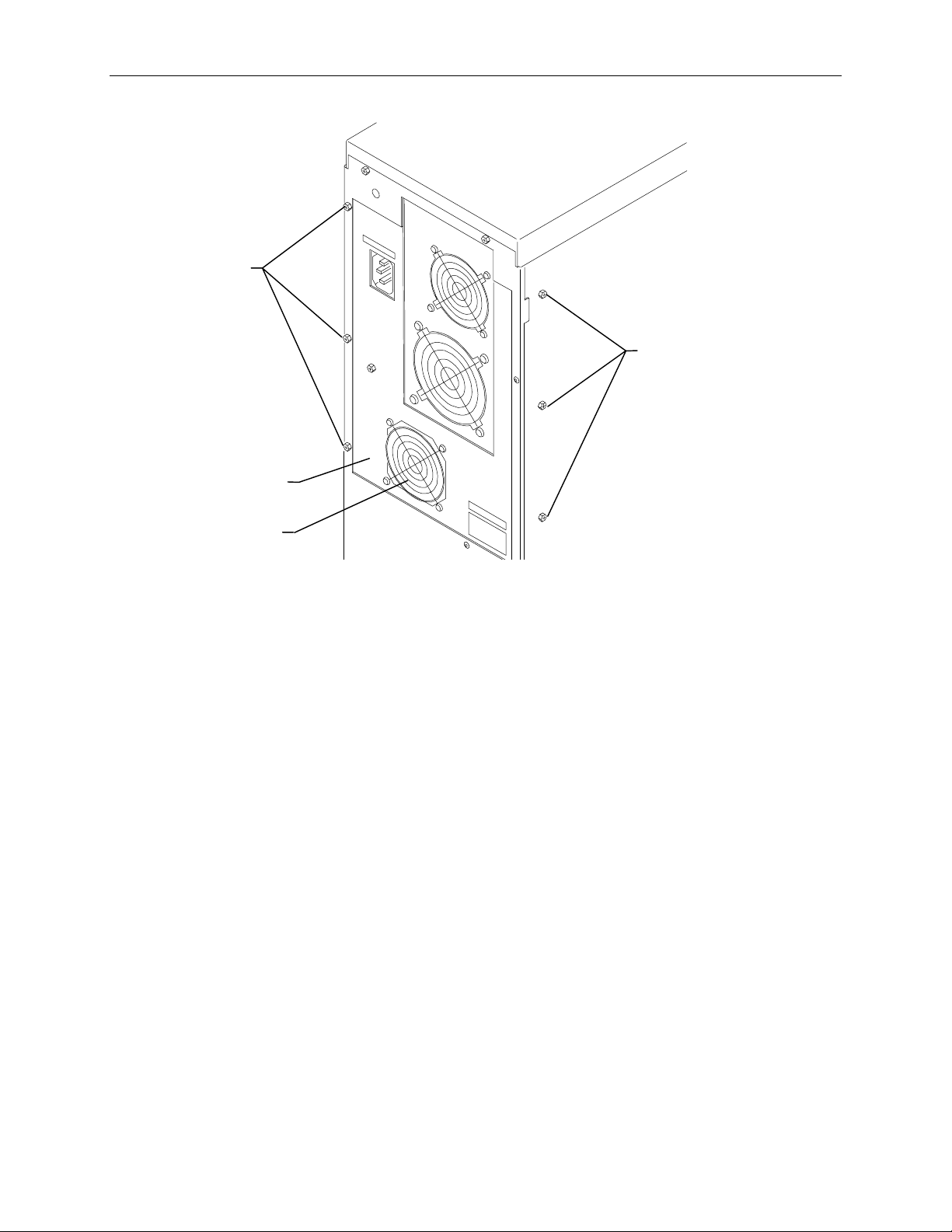
Screws
Power Supply
Access Panel
71
Screws
System Disk
Fan
CAUTION Do not remove the two screws at the top of the chassis. The power supply will fall down, damaging the
system hard disk drive.
3. Disconnect the fan power cable from the system board J12.
4. Using a No. 1 Phillips screwdriver, remove the fan from the panel.
5. Attach the new fan to the back panel and connect the fan power cable to the system board.
6. Replace the back panel and close the base unit.
Page 80

72
Auxiliary Fan (CFAN1110)
For systems with the internal RAID subsystem, a fan between the power supply and internal RAID
section provides cooling to the RAID disk drives.
To replace the auxiliary fan:
1. Open the base unit and remove the necessary parts as described in Chapter 3.
2. Remove power supply as described in, “Fixed Power Supply MPWS 131” on page 62.
3. Disconnect the fan power cable from the system board connector J12.
4. Using a short No. 1 Phillips screwdriver, remove the screws securing the fan to the fan assembly.
5. Remove the fan assembly from the base unit, and remove the fan from the assembly.
6. Attach the new fan to the fan assembly.
7. Connect the fan power cable to the system board.
8. Replace the power supply.
Page 81

73
5 Upgrading the System
You can upgrade your server by adding processors, memory, internal or external SCSI devices (such as
disk drives and tape drives), and option boards. This chapter also describes how to use the System
Configuration Utility (SCU) when adding ISA option boards, non-compliant PCI option boards, and
PC Card devices.
WARNING Leave the AC power cord from the InterServe 610 and 620 base unit connected to the AC wall
outlet to maintain safety ground. If the AC power cord is disconnected, you could be injured or
cause damage to the system.
WARNING Hazardous voltages exist inside the InterServe 630 and 640 base unit. Disconnect the AC power
cord from the base unit before upgrading the system. If the AC power cord remains connected,
you could be injured or cause damage to the system.
CAUTION The parts inside the base unit are designed to fit within very tight tolerances; some force is required to
remove or insert parts. However, if you cannot remove or install a part properly, ensure that there are
no obstructions hindering the part.
Adding Processors
Single to dual processor upgrade kits include a CPU with attached heat sink, Voltage Regultor Module
(VRM), and a metal clip. Dual to quad upgrade kits contain two processors, two VRMS, two clips, a
processor module (MSMT310), and screws.
Single to Dual Upgrade
To upgrade a single processor system:
1. Open the base unit and remove the necessary parts as described in Chapter 3.
NOTE If full-length ISA option boards are installed, these must be removed to access the CPU sockets.
2. Find the empty processor socket (adjacent to the exisitng CPU) on the system board. Raise the
lever on the empty socket to open the socket.
3. Install the new CPU into the socket. The CPU socket is keyed to ensure proper insertion.
4. Lower the lever to lock the CPU in the socket.
5. Attach the clip over the new CPU. Examine how the clip on the first CPU is installed to see how it
should fit on the new CPU. Ensure each end of the clip fully engages the socket tabs.
6. Attach the VRM into the empty VRM socket. Ensure the release tabs in the VRM socket fully
engage the VRM.
The following figure shows the finished upgrade with the send CPU and VRM installed.
Page 82

74
CPU
VRM
Socket
Socket
Metal Clip
7. Replace the ISA option boards and close the base unit.
Dual to Quad Upgrade
To upgrade a dual processor system:
1. Open the base unit and remove the necessary parts as described in Chapter 3.
NOTE If PCI option boards are installed, these must be removed to access the quad processor sockets.
2. Remove the P6 bus termination card. The processor module will be installed in this location.
3. On the processor module, raise the lever on the empty sockets to open the sockets.
4. Install the CPUs into the sockets. The CPU sockets are keyed to ensure proper insertion.
5. Lower the lever to lock the CPU in the socket.
6. Attach a clip over each CPU. Ensure each end of the clip fully engages the socket tabs.
7. Attach the VRM into the empty VRM sockets. Ensure the release tabs in the VRM socket fully
engage the VRM.
The following figure shows the CPUs and VRMs installed on the processor module.
Page 83

75
VRMs
Processor
Module
CPUs (with
Heat Sinks)
Clips
8. Align the processor module with the sockets that previously held the P6 bus termination card and
carefully insert the module.
9. Press the processor module firmly into the sockets. Secure the module with screws supplied in the
kit.
10. Replace the PCI option boards and close the base unit.
Adding Memory
You can expand the system memory up to double the base memory. The memory upgrade kit from
Intergraph contains four SIMMs and a disposable antistatic wrist strap. If you purchase SIMMs from a
source other than Intergraph, they must meet the following specifications:
u
Type -- 72-pin single- or double-sided DRAM SIMM, 36-bit, parity-style pinout
u
Speed -- 60 ns
u
Voltage -- 5 volts
u
Controller -- ECC
u
Interleaving -- 2-way (2 banks full) and 4-way (4 banks full)
u
SIMM Sizes Supported -- 32 MB, 64 MB, 128 MB
Memory style: industry-standard parity-style 72-pin SIMM
SIMM width: 36 bit, single- or double-sided
SIMM speed: 60 ns
To avoid damaging the SIMMs and voiding the warranty, take the following precautions.
u
Do not bend, twist, drop, or otherwise handle the SIMMs carelessly.
u
Do not expose the SIMMs to moisture or extreme temperatures.
u
Do not remove the SIMMs from the antistatic bag until installation.
The following table shows valid memory configurations. Each bank contains two sockets, and both
sockets must be populated. Memory density must be the same in all populated sockets. NP designates
not populated.
Page 84

76
Supported
Memory
Bank 0 Bank 1 Bank 2 Bank 3
64 MB 2 x 32 MB NP NP NP
128 MB 2 x 64 MB NP NP NP
2 x 32 MB 2 x 32 MB NP NP
Supported
Memory
Bank 0 Bank 1 Bank 2 Bank 3
256 MB 2 x 128 MB NP NP NP
2 x 64 MB 2 x 64 MB NP NP
2 x 32 MB 2 x 32 MB 2 x 32 MB 2 x 32 MB
512 MB 2 x 128 MB 2 x 128 MB NP NP
2 x 64 MB 2 x 64 MB 2 x 64 MB 2 x 64 MB
1 GB 2 x 128 MB 2 x 128 MB 2 x 128 MB 2 x 128 MB
To install the memory upgrade:
1. Open the base unit and remove the necessary parts as described in Chapter 3.
2. Using a quarter-inch nutdriver, remove the graphics boards and other installed PCI option boards.
3. Remove the existing SIMMs from their sockets before adding new ones.
4. Remove the SIMMs from the static bag and install them in this order:
−
If the total number of installed SIMMs will be four, install the SIMMs in the Bank 1 sockets
first, then in the Bank 0 sockets.
−
If the total number of installed SIMMs will be eight, install the first SIMM in socket J58.
Install the remaining SIMMs in the next empty socket until socket J51 is the last socket
populated.
5. The following figure shows the socket layout.
Bank 0 J51
Bank 1 J52
Bank 2 J53
Bank 3 J54
Bank 0 J55
Bank 1 J56
Bank 2 J57
Bank 3 J58
6. Position the SIMM in the next available socket so that the notch faces the back of the base unit.
7. Insert the SIMM at a 60 degree angle, pressing it firmly into the socket.
Page 85

8. Push on the top edge of the SIMM until it snaps into the metal clips. The socket tabs must fit
inside the mounting holes of the SIMM.
9. Repeat steps 7 through 9 for the remaining SIMMs.
10. Replace the graphics and PCI option boards and close the base unit.
11. Restart the system. The new memory is recognized automatically.
Adding Internal SCSI Devices
You can install internal SCSI devices such as hard disk drives, tape drives, and CD-ROM drives in the
auxiliary drive bays of the server. However, a bracket must be removed from the destination bay prior
to installation. The bays are designed to accommodate one-inch high devices. If the device is more
than one inch high, then the bay underneath must be empty.
NOTE When installing a SCSI device, carefully follow the vendor’s instructions for setting the SCSI ID and
disabling the SCSI termination before installing the devices.
NOTE Systems with the internal RAID subsystem have one bay available for an option SCSI device. Systems
without internal RAID have five bays available.
77
To install an internal device in the auxiliary drive bay:
1. Open the base unit and remove the necessary parts as described in Chapter 3.
2. Select a bay to install the device and remove the blanking plate or other device from the
destination bay.
3. Remove the screw that secures the disk drive slide bracket from the destination bay, and remove
the bracket. Refer to the following figure.
Slide
Bracket
Screw
4. Disable the device’s SCSI termination, and set the device’s SCSI ID to an unused number.
5. If installing a hard disk drive, mount the disk drive into the slide bracket using four screws.
Page 86

78
Screw
NOTE Do not mount tape drives or CD-ROM drives to the slide bracket.
6. Slide the device into the drive bay and secure it to the metal chassis.
7. Connect the power cable and SCSI cable to the device.
8. Close the base unit.
9. Restart the system.
10. If necessary, install the device’s drivers and configure the device according to the vendor’s
instructions.
Slide
Bracket
Adding External SCSI Drives
You can add up to seven external SCSI devices to the server. The total length of the external SCSI
cables must not exceed 19.2 feet for Fast SCSI-2 devices.
NOTE The last device on the SCSI cable chain must supply active termination. All other external devices
must have SCSI termination disabled or removed.
To install an external SCSI device:
1. Set the device’s SCSI ID to an unused number and enable or disable the device’s SCSI termination
according to the note above and the vendor’s instructions.
2. Connect one end of the SCSI cable to the Fast SCSI-2 port on the back of the base unit. If external
devices are already installed, connect the SCSI cable to the available SCSI port on the last device
on the SCSI cable chain.
3. Connect the device to the other end of the SCSI cable.
4. If necessary, install the device drivers and configure the device according to the vendor’s
instructions.
Page 87
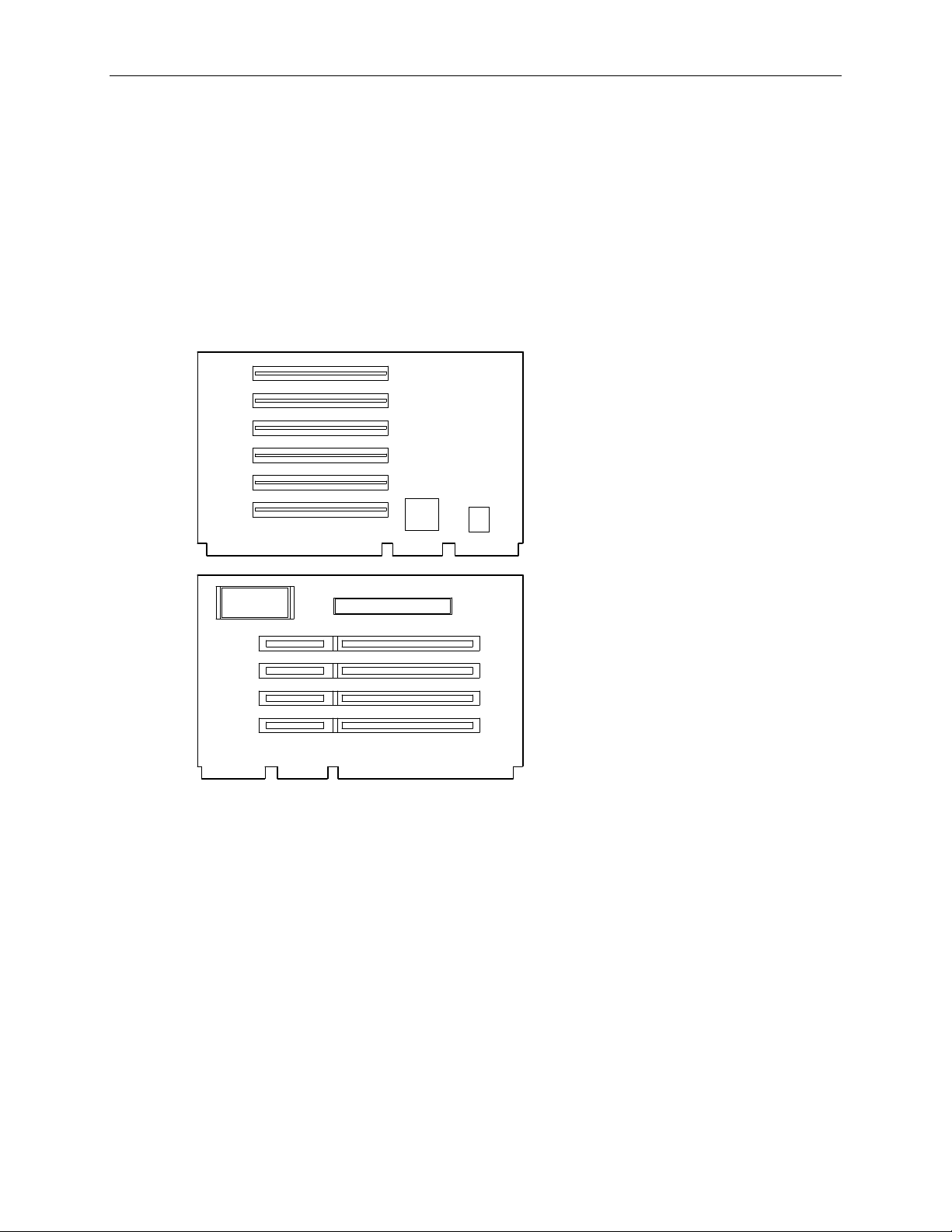
Adding Option Boards
This section briefly describes the differences between Peripheral Component Interconnect (PCI), ISA,
and Plug-n-Play (PnP) option boards. Instructions are also provided for installing option boards into
the system.
Option boards are installed on the riser card. PCI boards connect to side one of the riser card, while
ISA and PnP boards can be installed on side two. The following figure shows the slots on the riser
card.
NOTE PCI slots 1 through 4 are on the secondary PCI bus. PCI slots 5 and 6 are on the primary PCI bus.
79
PCI Boards
PCI 1
PCI 2
PCI 3
PCI 4
PCI 5
PCI 6
ISA 1
ISA 2
ISA 3
ISA 4
Side One
Side Two
PCI boards do not require manual system configuration when installing the board. The system BIOS
detects the board’s presence during startup and reads information from the board’s configuration
registers to assign the necessary system resources. Some PCI boards do not comply with the PCI
specification, and must be configured as if they were ISA boards using the System Configuration
Utility (SCU). Intergraph only provides PCI boards that comply with the specification.
NOTE PCI Slot 6 is not available in quad processor systems. If you plan to upgrade a dual-processor system
to four processors, the PCI card installed in PCI slot 6 will have to be moved.
CAUTION The system’s PCI slots are limited to 25 W power dissipation per the
Interconnect Specification
. Therefore, PCI boards must draw less than 25 watts of power.
Peripheral Component
To install PCI option boards:
1. Open the base unit and and remove the necessary parts as described in Chapter 3.
Page 88

80
2. Using a quarter-inch nutdriver, remove the blanking plate from an available PCI slot. Refer to the
following figure.
Blanking
Screw
Plate
3. Install the PCI board. Press firmly to ensure the board seats completely into the riser card slot.
4. Mount the board to the chassis using the screw removed previously.
5. Close the base unit.
6. Restart the system. The new PCI board is recognized and configured automatically during boot
up.
ISA and PnP Option Boards
ISA boards are not designed with internal registers that define the board configuration to the system
during startup. Therefore, you must run the SCU to define the board to the system. Run the SCU
before installing an ISA board to reserve system resources for the board and to prevent conflicts with
option boards already installed. Refer to “Using the System Configuration Utility” on page 83.
PnP boards are ISA boards that contain configuration registers like PCI boards. You do not have to
run the SCU to define a PnP board. During startup, the system BIOS automatically detects the installed
board and assigns the necessary system resources. Since PnP boards are ISA-based boards, they can be
installed in the same slots as ISA boards.
To install ISA and PnP boards:
1. Open the base unit and and remove the necessary parts as described in Chapter 3.
2. Disconnect the power cable and SCSI cable from the riser card. Refer to the following figure.
Page 89

SCSI Cable Power Cord
81
ISA I/O
Panel
Riser Card
3. Remove the screw securing the ISA I/O lock bracket as shown in the following figure. Pull up the
bracket to remove it. The internal cables have been omitted for clarity.
ISA I/O
Panel
Lock
Bracket
Page 90

82
4. Loosen the screw to allow the pivoting ISA board guide to swing toward the system fans. Refer to
the following figure.
Screw
ISA Board
Guide
5. Install the option board into the first available slot from the system board. Press firmly to ensure
the board seats completely in the slot.
6. Slide the pivoting board bracket over the edge of the ISA board; then tighten the screws.
7. Secure the ISA board to the chassis by installing the I/O lock bracket, which installs in only one
orientation. Mount the bracket to the chassis using the screw removed previously.
8. Close the base unit.
9. Restart the system. If you installed an ISA board, the installation is complete. If you installed a
PnP board, notice when the following message displays.
Hit DEL if you want to run SETUP
10. Press
DELETE to run AMIBIOS Setup.
11. When the main menu displays, select the Advanced Setup icon.
12. Click on the Boot to PnP Operating System parameter and select Enable in the Options menu.
Press
ENTER.
13. Exit AMIBIOS Setup and restart the system.
Page 91

Using the System Configuration Utility
The SCU is an MS-DOS utility that will not run in the Windows NT environment. Use the System
Utilities (SYSUTIL) diskette delivered with your system to boot the system into MS-DOS. The system
must be set to boot from the floppy disk drive (normally drive A) to use the SCU. If necessary, refer to
“Changing the System Boot Sequence” on page 85.
NOTE If installing a PC Card device or a non-compiant PCI card, which require specific system resources,
treat the device as if it were an ISA option board.
ISA Boards with a Configuration File
Some ISA boards are shipped with a diskette containing a configuration file. The configuration file can
be loaded to the system so that the BIOS reads this file to assign resources during startup. If you install
ISA boards that are shipped with a configuration diskette, follow this procedure.
NOTE If a configuration diskette is not delivered with the option board, refer to “ISA Boards without a
Configuration File” later in this chapter.
To define ISA boards with a configuration file:
1. Shut down and power off the system.
83
2. Insert the SYSUTIL diskette into the floppy diskette slot of the combo drive; then restart the
system.
3. When the MS-DOS Startup menu displays, select option 1 to run the SCU.
4. Use the arrow keys or the mouse to select Step 2 from the SCU Main Menu. Then press
add a board that was not detected or has not been installed.
A prompt displays requesting you to copy the configuration files needed to configure the system.
The configuration file is on a diskette provided by the ISA board manufacturer.
5. Press
6. Select the slot where the board will be installed. Only slots 1 through 4 are valid for the server.
7. When prompted to insert the source disk, insert the diskette containing the configuration file and
8. When prompted to insert the destination disk, insert the SYSUTIL diskette and press
9. Press
10. Select Step 4 to save the configuration, and then select Step 6 to exit the SCU.
11. Remove the diskette from the combo drive and restart the system.
ENTER to accept A:\ as the path to the configuration file.
press
ENTER.
configuration file from the option board manufacturer will be installed to the system and to the
SYSUTIL diskette.
ESC to return to the SCU Main Menu.
ISA Boards without a Configuration File
INSERT to
ENTER. The
Some ISA board vendors do not include configuration files with their boards. For these boards, you
must use the SCU to define the ISA board to the system (that is, manually create a configuration file).
Page 92

84
To define ISA boards without a configuration file:
1. Shut down and power off the system.
2. Insert the SYSUTIL diskette into the floppy diskette slot of the combo drive; then restart the
system.
3. When the MS-DOS Startup menu displays, select option 1 to run the SCU.
4. From the SCU Main Menu, select Step 2, then press
F6. The ISA Board Definition Menu displays
as shown in the following figure.
ISA Board Definition
Board Name:
Manufacturer:
Board Type:
[Save - F10] [Load - F9] [New - F2] [Delete - F4] [Quit - ES]
( ) Video Board
( ) Multifunction Board
( ) Mass Storage Device
Slot Type:
( ) 16 Bit
( ) 8 Bit
( ) 8 or 16 Bit
MemoryPortsIRQDMA
5. Enter the data specified in the manufacturer’s configuration instructions.
NOTE Use the TAB and arrow keys to move the cursor from field to field. Once inside the DMA, IRQ, and
Ports fields, press ENTER to display the sub-fields for entering the information.
6. Press F10 to save the data to the system.
7. Press
8. Press
ENTER to return to the ISA Board Definition Menu.
ESC to return to the SCU Main Menu.
9. Select Step 2. The Add and Remove Boards Menu displays.
10. Select the required slot number and press
11. Select
INSERT again to add the board. The ISA Board Database Menu displays.
12. Select the correct board name and press
INSERT.
ENTER.
13. When the Slot Selection Menu displays, select the required slot and press
14. Press
ESC to return to the SCU Main Menu.
15. Select Step 4 to save the configuration.
16. Select Step 6 to exit the SCU.
17. Remove the diskette from the combo drive; then restart the system.
ENTER.
Page 93

Changing the System Boot Sequence
To change the system boot sequence:
1. Restart the system.
85
2. Press
DELETE when the following message displays:
Press DEL if you want to run Setup
The AMIBIOS Setup Main Menu displays.
3. In the Setup menu, click the Advanced icon. A list of parameters displays.
4. Click the System Boot Up Sequence parameter. The Options menu displays, with a choice of boot
sequences. The default is C:, A:, which designates the system hard disk drive (C:) as the initial
boot device, followed by the floppy disk drive (A:).
5. Click the A:, C: parameter to reverse the boot sequence; then press
ENTER.
6. Select Exit and Save to exit AMIBIOS Setup.
7. Restart the system.
Until the boot sequence is changed back to C:, A:, the system will check for a bootable diskette in the
floppy disk drive before attempting to boot from the system’s boot disk drive.
Page 94

86
Page 95

Index
87
1
1 GB fixed disk drive (CDSK111), 41
servicing, 53
2
2 GB fixed disk drive (CDSK094), 42
servicing, 53
4
4 GB fixed disk drive (CDSK098), 42
servicing, 53
4 GB fixed disk drive (CDSK123), 43
servicing, 53
A
AC section
MESAN14, 6
AC section (MESAN14), 7
servicing, 64
Accessing the system
PCI access panel, 48
power supply access panel, 47
precautions, 46
protecting against electrostatic
discharge, 51
riser card brace and PCI board
guide, 49
top cover and side panels, 46
Adding
external SCSI devices, 78
internal SCSI devices, 77
memory, 75
option boards, 79
processors, 73
Alarm silence button
AC section (MESAN14), 8
Auxiliary fan
CFAN1110, 4
Auxiliary fan (CFAN1110), 43
servicing, 72
CDSK106, 4, 6
CD-ROM drive (CDSK106), 39
servicing, 53
CDSK094 (2 GB fixed disk drive), 42
servicing, 53
CDSK098 (4 GB fixed disk drive), 42
servicing, 53
CDSK106
CD-ROM drive, 4, 6
CDSK106 (CD-ROM drive), 39
servicing, 53
CDSK111 (1 GB fixed disk drive), 41
servicing, 53
CDSK123 (4 GB fixed disk drive), 43
servicing, 53
CFAN1110
auxiliary fan, 4
CFAN1110 (auxiliary fan), 43
servicing, 72
Changing
system boot sequence, 85
CINF029 (InterSite Server Monitor
board)
servicing, 67
Circuit breaker
AC section (MESAN14), 9
Closing the system, 52
Combo drive
MESAM86, 4, 6
Combo drive (MESAM86), 40
servicing, 55
D
DC output specifications
fixed power supply (MPWS131),
19
Document
conventions, vii
restrictions, vii
updates and feedback, vii
Dual-to-quad processor upgrade, 74
C
Cable connectors
fixed power supply (MPWS131),
20
CD-ROM drive
E
External SCSI devices
adding, 78
Page 96

88
F
Fixed disk drives, 41
servicing, 53
Fixed power supply
MPWS131, 4
Fixed power supply (MPWS131), 19
servicing, 62
FMEM13X
SIMMs, 68
I
Industry Standard Architecture (ISA)
option boards, 80
Information
additional system, viii
operating system, viii
Internal RAID section
MESAN15, 4, 6
Internal RAID section (MESAN15), 36
servicing, 56
Internal SCSI devices
adding, 77
Internal SCSI drives
servicing, 53
InterServe 610 (Non-RAID)
Functional diagram overview, 2
major assemblies, 1
riser card (MSMT280), 23
InterServe 610, 620 (Internal RAID)
functional diagram overview, 4
major assemblies, 3
riser card (MSMT280), 24
InterServe 630, 640
functional diagram overview, 6
major assemblies, 5
riser card (MSMT280), 25
InterSite Server Monitor board
(CINF029)
servicing, 67
K
Keylock switch
AC section (MESAN14), 8
Memory (SIMMs)
servicing, 68
MESAM86
combo drive, 4, 6
MESAM86 (combo drive), 40
servicing, 55
MESAN14
AC section, 6
MESAN14 (AC section), 7
servicing, 64
MESAN15
internal RAID section, 4, 6
MESAN15 (internal RAID section), 36
servicing, 56
MPCBD13
power distribution, 4
MPCBD13 (Power distribution board),
10
servicing, 66
MPCBD17
power distribution board, 6
MPCBD17 (Power distribution board),
13
servicing, 66
MPWS131
fixed power supply, 4
MPWS131 (fixed power supply), 19
servicing, 62
MPWS138
redundant power supplies, 6
MPWS138 (redundant power supply),
21
servicing, 63
MSMT280
riser card, 4, 6
MSMT280 (riser card), 23
servicing, 58
MSMT310 (processor module)
servicing, 58
MSMT311 (P6 bus termination card)
servicing, 59
MSMT313
system board, 4, 6
MSMT313 (system board), 27
servicing, 60
M
MCBLY690
option board fans, 4, 6
MCBLY690 (system disk fan), 43
servicing, 70
MCBLZ520
option board fans, 4, 6
Memory
adding, 75
O
Option board fan assembly
servicing, 69
Option board fans, 43
MCBLY690, 4, 6
MCBLZ520, 4, 6
Option boards, 79
adding, 79
Page 97

89
using the SCU, 83
P
P1 riser card connector pinout
fixed power supply (MPWS131),
20
P2 - P8 connector pinout
fixed power supply (MPWS131),
21
P6 bus termination card (MSMT311)
servicing, 59
P9 connector pinout
fixed power supply (MPWS131),
21
PCI access panel
accessing the system, 48
Peripheral Component Interconnect
(PCI)
option boards, 79
Plug and play (PnP)
option boards, 80
Power cables
AC section (MESAN14), 9
Power distribution
MPCBD13, 4
Power distribution board
MPCBD17, 6
Power Distribution Board (MPCBD13),
10
servicing, 66
Power Distribution Board (MPCBD17),
13
servicing, 66
Power supply access panel
accessing the system, 47
Power supply cable opening
AC section (MESAN14), 9
Precautions
accessing the system, 46
Processor module (MSMT310)
servicing, 58
Processors
adding, 73
Protecting against electrostatic
discharge
accessing the system, 51
R
Redundant power supplies
MPWS138, 6
Redundant power supply (MPWS138),
21
servicing, 63
Riser card
MSMT280, 4, 6
Riser card (MSMT280), 23
InterServe 610), 23
InterServe 610, 620, 24
InterServe 630, 640, 25
servicing, 58
Riser card brace and PCI board guide
accessing the system, 49
S
Safety interlock switch
AC section (MESAN14), 9
SIMMs
servicing, 68
SIMMs (FMEM13X), 68
Single-to-dual processor upgrade, 73
System board
MSMT313, 4, 6
System board (MSMT313), 27
cabling diagram and pinouts, 27
external ports, 32
jumper connectors, 30
servicing, 60
System Configuration Utility (SCU), 79,
80, 83
System disk fan (MCBLY690), 43
servicing, 70
T
Top cover and side panels
accessing the system, 46
Page 98

90
 Loading...