

Intel VCA 2, VCA1585LMV, Visual Compute Accelerator 2 Product Specification And Hardware Manual
Page 1

Intel® Visual Compute Accelerator 2
(Intel® VCA 2)
Product Specification and Hardware Guide
A reference document for server OEMs providing an overview of product features,
integration requirements, and validation guidelines.
Rev 1.3
November 2017
Intel® Server Products and Solutions
Page 2

<Blank page>
Page 3

Date
Revision
Changes
July 2017
1.0
Initial release.
October 2017
1.1
Edited for clarity. Removed sections on validation and operating systems.
November 2017
1.2
Updated supported memory to include non-ECC memory.
November 2017
1.3
Added section and appendix on validation.
Intel® VCA 2 Product Specification and Hardware Guide
Document Revision History
3
Page 4

Intel® VCA 2 Product Specification and Hardware Guide
Disclaimers
Intel technologies’ features and benefits depend on system configuration and may require enabled hardware, software, or service
activation. Learn more at Intel.com, or from the OEM or retailer.
You may not use or facilitate the use of this document in connection with any infringement or other legal analysis concerning Intel
products described herein. You agree to grant Intel a non-exclusive, royalty-free license to any patent claim thereafter drafted which
includes subject matter disclosed herein.
No license (express or implied, by estoppel or otherwise) to any intellectual property rights is granted by this document.
The products described may contain design defects or errors known as errata which may cause the product to deviate from
published specifications. Current characterized errata are available on request.
Intel disclaims all express and implied warranties, including without limitation, the implied warranties of merchantability, fitness
for a particular purpose, and non-infringement, as well as any warranty arising from course of performance, course of dealing, or
usage in trade.
Copies of documents which have an order number and are referenced in this document may be obtained by calling 1-800-548-4725
or by visiting www.intel.com/design/literature.htm.
Intel, the Intel logo, Xeon, and Intel Xeon Phi are trademarks of Intel Corporation or its subsidiaries in the U.S. and/or other countries.
*Other names and brands may be claimed as the property of others.
Copyright © 2017 Intel Corporation. All rights reserved.
4
Page 5

Intel® VCA 2 Product Specification and Hardware Guide
Table of Contents
1. Introduction .................................................................................................................................................................. 7
1.1 Document Outline............................................................................................................................................................. 7
2. Product Overview ........................................................................................................................................................ 8
2.1 Order Information ............................................................................................................................................................. 8
2.2 Feature Set ........................................................................................................................................................................... 8
2.3 Host System Required BIOS Features ...................................................................................................................... 9
2.4 Host System Minimum Memory Requirements .................................................................................................... 9
2.5 Architecture Block Diagram ....................................................................................................................................... 10
3. Board Specifications and Support Requirements ............................................................................................. 11
3.1 Mechanical Specification ............................................................................................................................................ 11
3.2 Card Assembly................................................................................................................................................................. 12
3.3 Thermal and Airflow Specification .......................................................................................................................... 13
3.4 Power Specification ....................................................................................................................................................... 14
3.4.1 12 V AUX Power Connector Specification and Pinout ................................................................................... 14
4. Host Server Validation Guidelines ....................................................................................................................... 16
4.1 Quick Validation Guide for OEMs ............................................................................................................................ 16
4.1.1 PCIe* Device Discovery and Enumeration ........................................................................................................... 16
4.1.2 Node Availability ............................................................................................................................................................. 18
4.1.3 Ethernet Over PCIe* Network Performance ........................................................................................................ 19
4.1.4 Transcoding Benchmark for Simultaneous AVC-AVC Transcodes ........................................................... 20
4.1.5 Temperature Profile ...................................................................................................................................................... 20
4.2 Validating Hardware Compatibility ......................................................................................................................... 21
4.3 Host Server BIOS Guidelines ..................................................................................................................................... 21
4.4 Host Server PCIe* Reset Guidelines ....................................................................................................................... 21
5. Memory Support ....................................................................................................................................................... 22
5.1 Memory Population Rules .......................................................................................................................................... 22
5.2 Supported Memory ....................................................................................................................................................... 22
5.3 Memory Compatibility List ......................................................................................................................................... 23
6. Operating System Support ..................................................................................................................................... 24
6.1 Supported Hypervisors ................................................................................................................................................ 24
6.2 Guest Operating System ............................................................................................................................................. 24
Appendix A. Full PCIe* Dump ................................................................................................................................... 25
Appendix B. Glossary ................................................................................................................................................. 45
Appendix C. Additional Collateral ........................................................................................................................... 46
5
Page 6

Intel® VCA 2 Product Specification and Hardware Guide
List of Figures
Figure 1. Product architectural block diagram ............................................................................................................................. 10
Figure 2. Intel® VCA 2 dimensions ...................................................................................................................................................... 11
Figure 3. Intel® VCA 2 detachable components ........................................................................................................................... 12
Figure 4. Standard airflow pattern ..................................................................................................................................................... 13
Figure 5. Non-standard airflow pattern ........................................................................................................................................... 13
Figure 6. Intel® VCA 2 card power connectors .............................................................................................................................. 14
Figure 7. 2x3 pin 12 V AUX power connector pin diagram ..................................................................................................... 14
Figure 8. 2x4 pin 12 V AUX power connector pin diagram ..................................................................................................... 15
Figure 9. PCIe* device discovery ......................................................................................................................................................... 16
Figure 10. Node PCIe* link health....................................................................................................................................................... 17
Figure 11. PLX PCIe* link health ......................................................................................................................................................... 18
Figure 12. CPU status after host reset .............................................................................................................................................. 18
Figure 13. CPU status after booting operating system ............................................................................................................. 19
Figure 14. Temperature profile while transcoding ..................................................................................................................... 20
Figure 15. Intel® VCA 2 card DIMM slots.......................................................................................................................................... 22
List of Tables
Table 1. Order information ...................................................................................................................................................................... 8
Table 2. Board feature set ........................................................................................................................................................................ 8
Table 3. Processor feature set ................................................................................................................................................................ 8
Table 4. Requirements for standard airflow pattern .................................................................................................................. 13
Table 5. Requirements for non-standard airflow pattern ........................................................................................................ 13
Table 6. 2x3 pin 12 V AUX power connector pinout .................................................................................................................. 14
Table 7. 2x4 pin 12 V AUX power connector pinout .................................................................................................................. 15
Table 8. Bidirectional bandwidth measurement results ........................................................................................................... 19
Table 9. Transcoding benchmark results ........................................................................................................................................ 20
Table 10. Supported memory types ................................................................................................................................................. 22
Table 11. ECC memory compatibility list ........................................................................................................................................ 23
Table 12. Non-ECC memory compatibility list ............................................................................................................................. 23
6
Page 7

Intel® VCA 2 Product Specification and Hardware Guide
1. Introduction
This document provides a high-level overview of the product features, functions, and support requirements
of the Intel® Visual Compute Accelerator 2 (Intel® VCA 2) (VCA1585LMV).
1.1 Document Outline
This document is divided into the following chapters:
Chapter 1 – Introduction
Chapter 2 – Product Overview
Chapter 3 – Board Specifications and Support Requirements
Chapter 4 – Host Server Validation Guidelines
Chapter 5 – Memory Support
Chapter 6 – Operating System Support
7
Page 8
Intel® VCA 2 Product Specification and Hardware Guide
Product Image
Details
Description
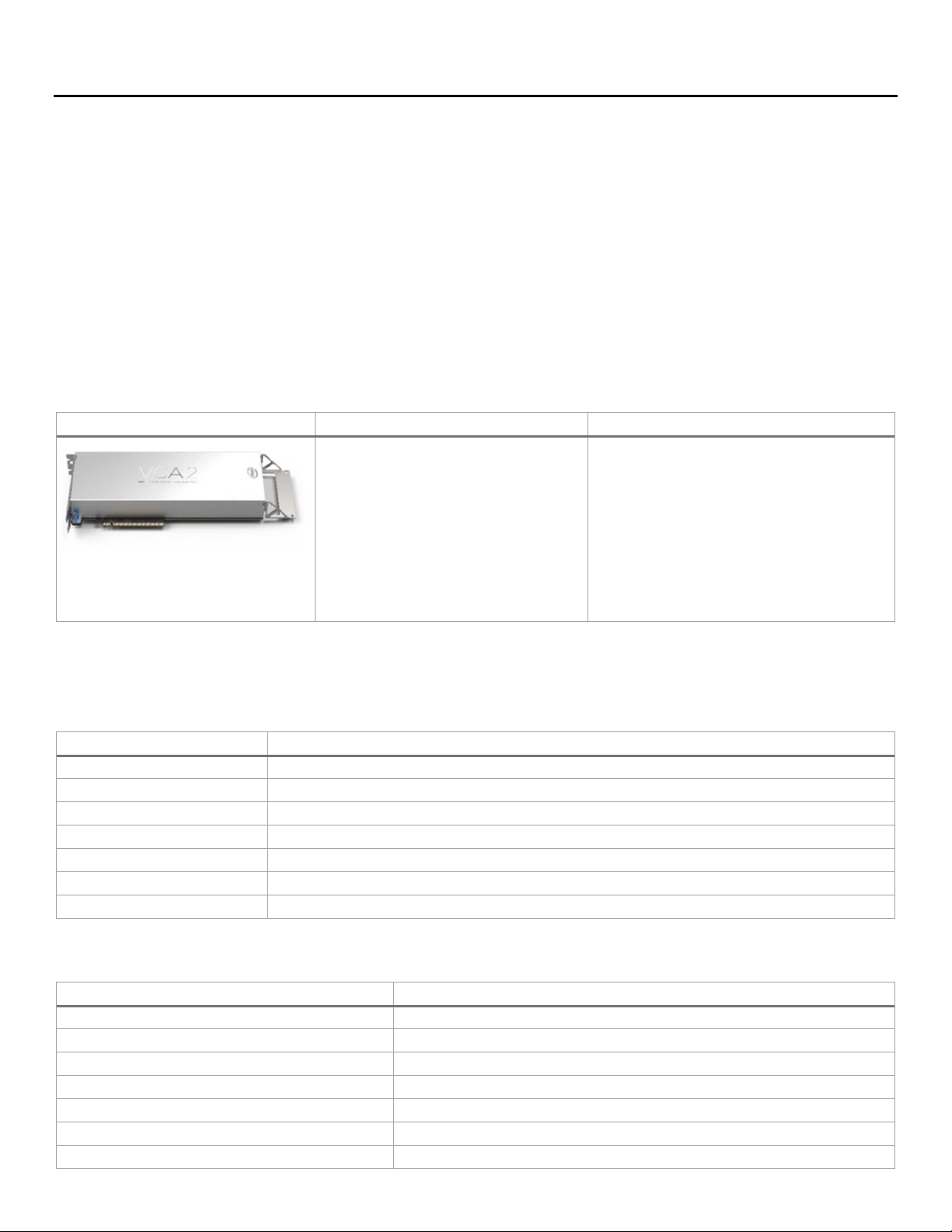
Intel® Visual Compute Accelerator 2
(Intel® VCA 2) VCA1585LMV
iPC
VCA1585LMV
MM#
954907
UPC
7 35858 33453 2
EAN
5 0320370 99127
MOQ
1
Product type
PCIe* Add-in Card
Includes:
(1) – PCIe* add-in-card with
(3) Intel® Xeon® processor E3-1500 v5
product family
(6) DIMM slots – (2) DIMMs/CPU
(1) – Quick Start Guide
Feature
Description
Form factor
Full-length, full-height, double-width PCIe* card
CPU
(3) Intel® Xeon® processor E3-1585L v5
Max TDP
235 W
Memory
DDR4 ECC SODIMMs, 2 channels per CPU, up to 64 GB per CPU, up to 192 GB per card
PCIe* configuration
Gen3, x16, 8 lanes per CPU
BIOS
(1) 16 MB SPI flash per CPU
Operating system support
CentOS* 7.2 , Windows Server* 2016, Windows* 10, Xen or KVM support if using hypervisor
Feature
Description
Processor Type
Intel® Xeon® processor E3-1585L v5
Cache
8 MB
Instruction set
64-bit
Instruction set extensions
SSE4.1/4.2 AVX 2.0
# of cores
4
# of threads
8
Processor base frequency
3.0 GHz
2. Product Overview
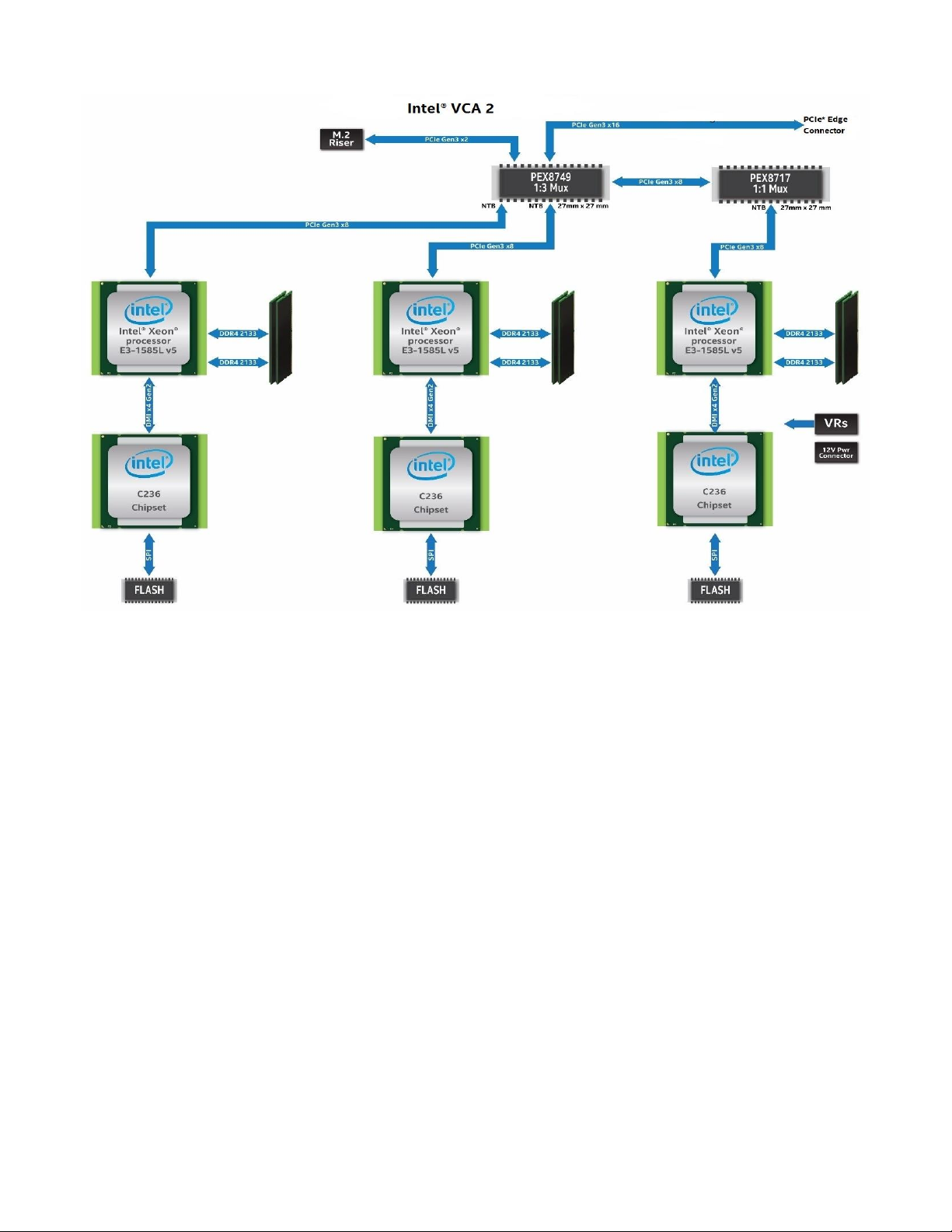
The Intel® Visual Compute Accelerator 2 (Intel® VCA 2) equips Intel® Xeon® Scalable processor and Intel®
Xeon® processor E5-based platforms with Iris® Pro Graphics and Intel® Quick Sync Video media transcode
capabilities. Comprised of three Intel Xeon processors E3 1585L v5, this PCIe* add-in card delivers
outstanding total cost of ownership and is supported by a rich ecosystem of server OEMs, ISVs, and
solutions. Applications include:
Broadcast – Ultra-high channel density with high visual quality.
Remotely rendered graphics – High video quality, low latency graphics for enterprise productivity and
anytime anywhere gaming.
Multi-party communication – Video-enabled B2B, B2C, and C2C communication with massive scaling
2.1 Order Information
Table 1. Order information
2.2 Feature Set
8
Table 2. Board feature set
Table 3. Processor feature set
Page 9

Intel® VCA 2 Product Specification and Hardware Guide
Feature
Description
Max turbo frequency
3.7 GHz
TDP
45 W
Max memory size (dependent on memory type)
64 GB
Max # of memory channels
2
ECC memory supported
Yes
Processor graphics
Iris® Pro graphics P580
Graphics base frequency
350 MHz
Graphics max dynamic frequency
1.0 GHz (capped in BIOS)
Graphics video max memory
32 GB
Execution units
72
Intel® Quick Sync Video
Yes
2.3 Host System Required BIOS Features
The host system BIOS must be configured to enable large memory-mapped input/output (MMIO), and allow
for large per-device base address register (BAR) allocations. BAR must have 64-bit address enabled.
The minimum requirements for BAR and MMIO are:
MMIO mapping above 4 GB is enabled
Minimum MMIO size is 4 GB/CPU (node)
For example, on Intel® Server Board S2600WT based systems, this can be enabled in BIOS setup by
configuring the following two options on the PCI Configuration screen.
Set Memory Mapped Above 4 GB to Enabled
Set Memory Mapped IO size to 256 GB
2.4 Host System Minimum Memory Requirements
The host system must have sufficient free RAM (after accounting for operating system, running services, and
applications) to load the bootable image for each node to be simultaneously booted. (For example, if a 2 GB
bootable image would be booted simultaneously on four cards (12 nodes), there must be at least 24 GB (2
GB x 12 nodes) of free RAM when the boot command is issued.)
9
Page 10
Intel® VCA 2 Product Specification and Hardware Guide
2.5 Architecture Block Diagram
Figure 1. Product architectural block diagram
10
Page 11
Intel® VCA 2 Product Specification and Hardware Guide
3. Board Specifications and Support Requirements
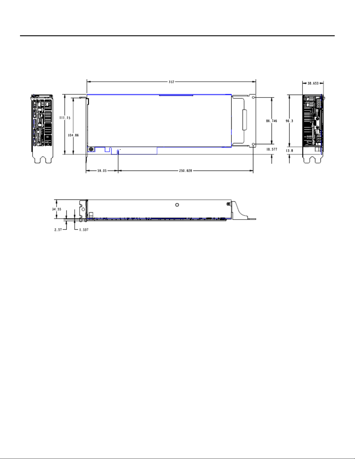
3.1 Mechanical Specification
Intel® VCA 2 is a “near” full-length, full-height, double-width PCIe* 3.0 x16 add-in card. It includes a bracket
that extends the card to full length for systems that fully support the PCIe specification.
Figure 2. Intel® VCA 2 dimensions
11
Page 12
Intel® VCA 2 Product Specification and Hardware Guide
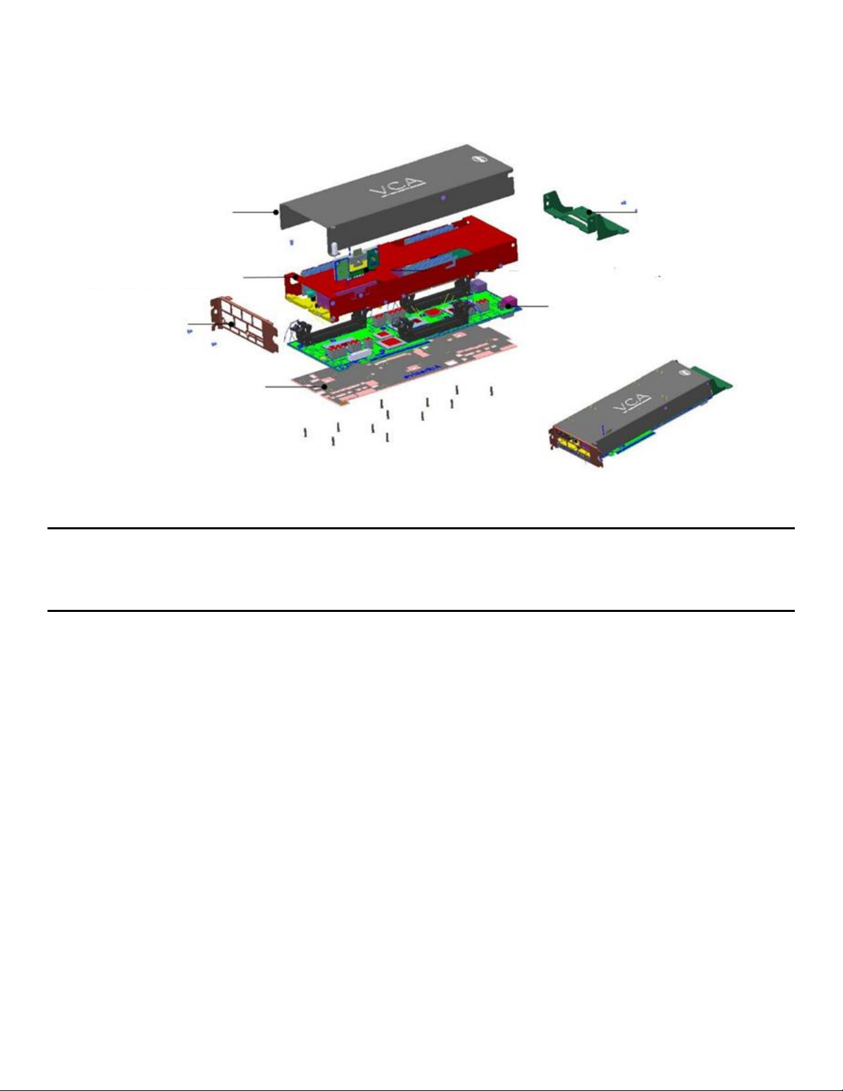
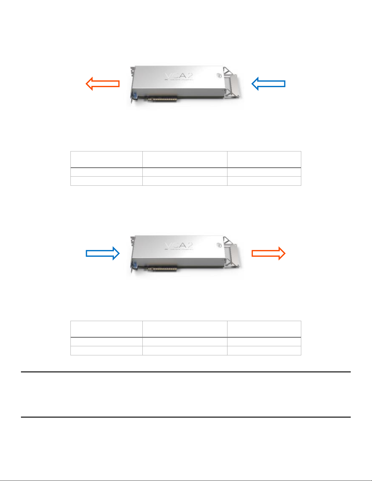
Backplate and insulator
PCIe* extender
bracket
3.2 Card Assembly
The Intel VCA 2 assembly consists of several detachable components to allow for card configuration and
serviceability. Figure 3 displays the full card assembly.
Figure 3. Intel® VCA 2 detachable components
Advisory Note: Intel VCA 2 must have the provided mechanical support bracket (or other custom support
bracket) mounted to the card to ensure proper support when installed in the system. Failure to properly
support the installed card may cause serious damage should the system be exposed to any level of shock or
vibration or is transported to the end user location.
When in operation, the card temperature will rise. The cosmetic cover, thermal module, and duct must be in
place to allow for proper airflow over and through the card assembly. Failure to have the card covers
installed results in overheating which may impact performance or proper operation of the card.
12
Page 13
Intel® VCA 2 Product Specification and Hardware Guide
Card Inlet Temperature
Flow Rate
(Cubic Feet per Minute (CFM))
Pressure Drop
(Inches of Water (“H2O))
45° C
25.5 CFM
0.476 “H2O
35° C
18.0 CFM
0.246 “H2O
Card Inlet Temperature
Flow Rate
(Cubic Feet per Minute (CFM))
Pressure Drop
(Inches of Water (“H2O))
35 °C
24.1 CFM
0.208 “H2O
25 °C
19.0 CFM
0.196 “H2O
Airflow in
Airflow out
Airflow out
Airflow in
3.3 Thermal and Airflow Specification
Figure 4 and Table 4 identify the thermal, airflow, and air pressure requirements that must be met by a
chassis following the front-to-back air flow pattern of a common system.
Figure 4. Standard airflow pattern
Table 4. Requirements for standard airflow pattern
Some custom chassis configurations may orient the card such that the airflow is reversed from the standard
airflow pattern shown above. In these non-standard system configurations, the thermal, airflow, and air
pressure boundary conditions must meet the following requirements.
Figure 5. Non-standard airflow pattern
Table 5. Requirements for non-standard airflow pattern
Note: Intel VCA 2 CPU core temperatures must remain at or below 96 °C (204.8 °F). CPUs begin to throttle
once they reach 100 °C (216 °F), impacting card performance. Should CPU temperatures continue to rise, the
card may shut down due to a CPU Thermal Trip event. Should such events occur, adjustments must be made
to the system fan speed controls to ensure increased airflow to the card. The vcactl temp command of the
vcactl utility may be used to monitor card CPU core temperatures.
13
Page 14
Intel® VCA 2 Product Specification and Hardware Guide
Pin #
Description
1
12 V
2
12 V
3
12 V
4
GND
5
GND
6
GND
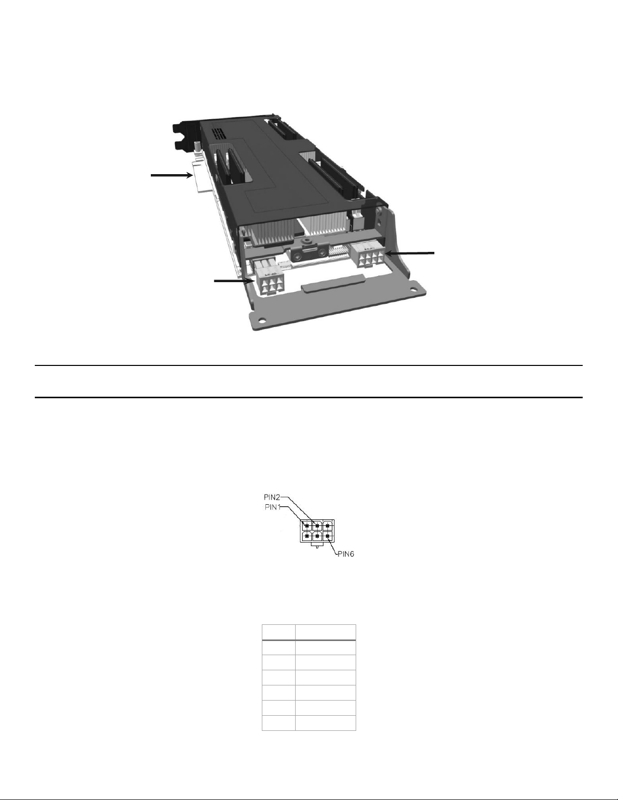
(2 x 3) Pin 12V AUX
up to 75W
(2 x 4) Pin 12V AUX
up to 150W
PCIe* Edge
up to 75W
3.4 Power Specification
Intel VCA 2 has a maximum TDP of 235 W. Per the PCIe specification, the PCIe x16 connector can support up
to 75 W. The remaining power to the card must be supplied via the 2x3 (75 W) and 2x4 (150 W) 12 V AUX
power connectors on the card as shown in Figure 6.
Connector
Figure 6. Intel® VCA 2 card power connectors
Note: Intel VCA 2 does not ship with cables. Contact the system supplier for 12 V AUX power cables
appropriate for the system to which the card is being installed. See 6 for Intel® Server System support.
3.4.1 12 V AUX Power Connector Specification and Pinout
3.4.1.1 2x3 Pin 12 V AUX Power Connector
Vendor – Lotes*
Vendor Part # - APOW0001-P001C01
Figure 7. 2x3 pin 12 V AUX power connector pin diagram
Table 6. 2x3 pin 12 V AUX power connector pinout
14
Page 15

Intel® VCA 2 Product Specification and Hardware Guide
Pin #
Description
1
12 V
2
12 V
3
12 V
4
GND
5
GND
6
GND
7
GND
8
GND
3.4.1.2 2x4 Pin 12 V AUX Power Connector
Vendor – Lotes
Vendor Part # - APOW0002-P001C01
Figure 8. 2x4 pin 12 V AUX power connector pin diagram
Table 7. 2x4 pin 12 V AUX power connector pinout
15
Page 16

Intel® VCA 2 Product Specification and Hardware Guide
4. Host Server Validation Guidelines
4.1 Quick Validation Guide for OEMs
For this section, the following example configuration is assumed:
Host
o System: 2U x 2 GPU server
o CPU: 2x Intel® Xeon® E5-2630 v4
o Memory: 16 GB per socket (2x DDR4 8 GB 2400 MHz DIMMs)
o Fans set to meet CFM requirements defined in Section 3.3 at card inlet temperature 35 °C.
Intel® VCA
o System: 2x Intel VCA 2
o Memory: 32 GB per node (2x DDR4 16 GB 2133 MHz DIMMs)
o Firmware: VCA_EXT_2.0.283
4.1.1 PCIe* Device Discovery and Enumeration
When recognized, each Intel VCA 2 lists the set of PCIe* devices shown in Figure 9. B/D/F may change based
on the system setup, but the number of devices (13) and names should match. To display the device list, use
the following command:
lspci | grep “(rev ca)”
Figure 9. PCIe* device discovery
For a quick check on PCIe link health, check the link status properties for each device. For a full example
dump refer to Appendix A. Link speed should be Gen 3 8 Gt/s. Lane count for the main PLX 8749 device
depends on host configuration; x16 is the highest available lane count interfacing with the host. Individual
nodes are expected to be Gen 3 8 GT/s x8 links. Not every port from PLX 8746 is used, so expect one link to
be 0 lanes Gen 1.
16
Page 17

Intel® VCA 2 Product Specification and Hardware Guide
For the node, use the following command:
lspci –s 84:00.0 –vv
Figure 10. Node PCIe* link health
17
Page 18

Intel® VCA 2 Product Specification and Hardware Guide
For the edge connector PLX, use the following command:
lspci –s 82:00.0 –vv
Figure 11. PLX PCIe* link health
4.1.2 Node Availability
To quickly verify that each node is up, run a status command from the Intel VCA utility. Return data is
expected to be a list of CPUs per card and each individual state. It is expected that there are three CPUs
listed per card and all are in the same status after a successful boot. To display CPU status, use the following
command:
vcactl status
Right after host reset, it is expected to see the status shown in Figure 12.
After booting the node’s operating system and network services are up, it is expected to see the status
shown in Figure 13.
Figure 12. CPU status after host reset
18
Page 19

Intel® VCA 2 Product Specification and Hardware Guide
Node
Run #
Host to Node
Node to Host
Data Sent
(GBytes)
Data Received
(GBytes)
Bandwidth
(Gbits/sec)
Data Sent
(GBytes)
Data Received
(GBytes)
Bandwidth
(Gbits/sec)
1
1
500
500
14.3
472
472
13.5 2 501
501
14.3
465
465
13.3 3 501
501
14.3
471
471
13.5 4 505
505
14.5
473
473
13.6 5 500
500
14.3
470
470
13.5
2
1
499
499
14.3
544
544
15.6
2
499
499
14.3
544
544
15.6 3 500
500
14.3
544
544
15.6 4 499
499
14.3
545
545
15.6
5
499
499
14.3
543
543
15.6
3
1
495
495
14.2
566
566
16.2 2 496
496
14.2
561
561
16.1 3 495
495
14.2
566
566
16.2 4 498
498
14.3
569
569
16.3 5 495
495
14.2
563
563
16.1
Average
14.28667
15.08667
Total Average
14.68667
Figure 13. CPU status after booting operating system
4.1.3 Ethernet Over PCIe* Network Performance
This test is a bidirectional bandwidth measurement. Both node and server are listening to each other. There
are five runs for each load.
Tool: iperf3, default parameters, 5 loops by 300 s each, TCP
Environment: 3 nodes bidirectional MTU-64k on x16 slot, bare metal-bare metal
Server setup on host: iperf3 –s
Server setup on node: iperf3 –s
iperf run in host: iperf3 –t 300 –c 172.31.x.1
iperf run in node: iperf3 –t 300 –c 172.31.x.254
Target: Total average bandwidth > 14 Gbits/sec per node
Results: See Table 8
Table 8. Bidirectional bandwidth measurement results
19
Page 20

Intel® VCA 2 Product Specification and Hardware Guide
Node
FPS
Maximum Transcodes
Node 0-1
30.23
17
Node 0-2
30.32
17
Node 0-3
30.31
17
Node 1-1
30.32
17
Node 1-2
30.26
17
Node 1-3
30.35
17
0
10
20
30
40
50
60
70
80
0 40 80 120 160 200 240 280 320 360 400 440 480 520 560
Temperature (
°C)
Time (seconds)
4.1.4 Transcoding Benchmark for Simultaneous AVC-AVC Transcodes
This test attempts to extract the maximum number of simultaneous AVC transcodes while maintaining a
minimum of 30 FPS using Intel® Media Server Studio and a web-available video sample.
Target: Most number of simultaneous AVC transcodes achieved while keeping 30 FPS (real-time)
Test configuration: 2x Intel VCA 2 with all 6 nodes running simultaneous transcoding
Environment: Bare metal, non-persistent image
Transcoding software: Intel Media Server Studio 2017 (available at https://software.intel.com/
en-us/intel-media-server-studio)
Input file: blue_sky_1080p25_3min.h264 (available at https://media.xiph.org/ldv/pub/
test_sequences/1080p/)
PAR file details:
-async 3 -hw -u 7 -cqp -qpi 24 -qpp 26 -qpb 28 -gop_size 61 -dist 3 -i::h264
/input/blue_sky_1080p25_3min_18.h264 -o::h264 /dev/null
Results: See Table 9
Table 9. Transcoding benchmark results
4.1.5 Temperature Profile
The temperature while booted in idle mode is ~35 °C. Temperature during workload is expected to reach
~60 °C. During transcoding workload, the script runs the load twice to ensure frame rate achieved is correct,
hence the temperature curve between runs is expected.
20
Figure 14. Temperature profile while transcoding
Page 21

Intel® VCA 2 Product Specification and Hardware Guide
4.2 Validating Hardware Compatibility
Mechanical, thermal, and power supply – Refer to chapters in this guide on mechanical, airflow, and
power supply specifications.
Shock and vibration – There are no special requirements for testing shock and vibration. Use the
standard testing procedure for PCIe* devices.
Power cycling – AC, DC, reset. Recommend minimum of ten boards (20 preferred) cycled 700 times
each at expected production ambient temperature with not failures.
4.3 Host Server BIOS Guidelines
BIOS enumerates and recognizes PCIe add-in cards, x16 Gen3
BIOS supports large MMIO regions ≥ 256 GB
BIOS must support BAR up to 64 GB per device
4.4 Host Server PCIe* Reset Guidelines
Signal – PERST_N, which is the PCIe reset signal coming from host
Duration – Not relevant, but 10 ms is suggested
Number of resets – Not limited, but strongly suggested two as maximum
Time between resets – Recommended to be at least three seconds
21
Page 22

Intel® VCA 2 Product Specification and Hardware Guide
Memory Type
Memory Size
Speed
Ranks per DIMM
SODIMM DDR4L ECC
8GB, 16GB
2133
Single-rank, dual-rank
SODIMM DDR4L Non-ECC
4GB, 8GB, 16GB
2133
Single-rank, dual-rank
5. Memory Support
Intel® VCA 2 includes three processors identified as CPU 1-3. Each of the three processors includes two
memory channels identified as A and B. Each memory channel supports one SODIMM socket. Each processor
can support up to 64 GB of memory. Figure 15 below identifies the SODIMM sockets for each processor.
Figure 15. Intel® VCA 2 card DIMM slots
5.1 Memory Population Rules
Note: Although mixed DIMM configurations may be functional, Intel only supports and performs validation
with cards that are configured with identical DIMMs installed across all CPUs
All DIMMs must be DDR4 DIMMs.
Only Error Correction Code (ECC) enabled DIMMs are supported.
All processors must have at least one DIMM installed.
DIMM slots for each processor must be installed in order, beginning with DIMM Slot A.
When only one DIMM is installed for any given processor, it must be populated in the DIMM A slot.
5.2 Supported Memory
Intel VCA 2 has support for the following memory types:
Table 10. Supported memory types
22
Page 23

Intel® VCA 2 Product Specification and Hardware Guide
Vendor
8 GB
16 GB
Micron*
MTA18ASF1G72HZ-2G3B1
MTA18ASF2G72HZ-2G3B1
SK-Hynix*
HMA41GS7AFR8N-TF
HMA82GS7MFR8N-TF
Samsung*
M474A1G43DB1-CRC
M474A2K43BB1-CRC
Crucial*
CT16G4TFD824A
Vendor
4 GB
8 GB
16 GB
HyperX*
HX421S13IB/4
HX421S13IB/8
HX421S13IB/16
Crucial*
CT4G4SFS8213
CT8G4SFS8213
CT16G4SFD8213
5.3 Memory Compatibility List
The following lists of memory have been validated for use on Intel VCA 2. This list will be updated as
additional DIMMs are tested.
Table 11. ECC memory compatibility list
Table 12. Non-ECC memory compatibility list
23
Page 24

Intel® VCA 2 Product Specification and Hardware Guide
6. Operating System Support
Note: All utility software and boot images referenced in this section can be downloaded at
https://downloadcenter.intel.com/product/98092.
Note: Supported operating systems and instructions for bringing up Intel® VCA 2 are provided in the Intel®
Visual Compute Accelerator Family Software Guide:
https://www.intel.com/content/www/us/en/support/server-products/server-accessories/000016708.html.
Intel VCA 2 boots the operating system from the host using a technology known as leverage boot. A vcactl
utility is used to perform all boot operations. The utility loads the operating system into a RAMDisk that the
CPUs boot from.
Users have the option of downloading one of several different boot images available from the Intel website
or creating their own boot image. Refer to the Intel® Visual Compute Accelerator Product Family Software
Guide for instructions on how to build a boot image.
6.1 Supported Hypervisors
Xen
KVM
6.2 Guest Operating System
Intel VCA 2 supports any operating system supported by Iris® Pro graphics, Intel® Graphics Virtualization
Technology (Intel® GVT-d) virtualization, and the Intel® Media Server Studio.
24
Page 25

Intel® VCA 2 Product Specification and Hardware Guide
Appendix A. Full PCIe* Dump
For more information on PCIe* link health for Intel VCA 2, refer to Section 4.1.1.
82:00.0 PCI bridge: PLX Technology, Inc. Device 8749 (rev ca) (prog-if 00
[Normal decode])
Control: I/O+ Mem+ BusMaster+ SpecCycle- MemWINV- VGASnoop- ParErr-
Stepping- SERR- FastB2B- DisINTx+
Status: Cap+ 66MHz- UDF- FastB2B- ParErr- DEVSEL=fast >TAbort- <TAbort-
<MAbort- >SERR- <PERR- INTx-
Latency: 0, Cache Line Size: 32 bytes
Interrupt: pin A routed to IRQ 48
NUMA node: 1
Region 0: Memory at c8400000 (32-bit, non-prefetchable) [size=256K]
Bus: primary=82, secondary=83, subordinate=89, sec-latency=0
I/O behind bridge: 00008000-00009fff
Memory behind bridge: c8000000-c83fffff
Prefetchable memory behind bridge: 000003fd00000000-000003ffffffffff
Secondary status: 66MHz- FastB2B- ParErr- DEVSEL=fast >TAbort- <TAbort-
<MAbort- <SERR- <PERR-
BridgeCtl: Parity+ SERR+ NoISA- VGA- MAbort- >Reset- FastB2B PriDiscTmr- SecDiscTmr- DiscTmrStat- DiscTmrSERREn Capabilities: [40] Power Management version 3
Flags: PMEClk- DSI- D1- D2- AuxCurrent=0mA PME(D0+,D1-,D2-
,D3hot+,D3cold+)
Status: D0 NoSoftRst+ PME-Enable- DSel=0 DScale=0 PME Capabilities: [48] MSI: Enable+ Count=1/8 Maskable+ 64bit+
Address: 00000000fee000d8 Data: 0000
Masking: 000000ff Pending: 00000000
Capabilities: [68] Express (v2) Upstream Port, MSI 00
DevCap: MaxPayload 2048 bytes, PhantFunc 0
ExtTag- AttnBtn- AttnInd- PwrInd- RBE+ SlotPowerLimit 25.000W
DevCtl: Report errors: Correctable- Non-Fatal+ Fatal+ Unsupported+
RlxdOrd+ ExtTag- PhantFunc- AuxPwr- NoSnoop+
MaxPayload 512 bytes, MaxReadReq 128 bytes
DevSta: CorrErr+ UncorrErr- FatalErr- UnsuppReq+ AuxPwr- TransPend LnkCap: Port #0, Speed 8GT/s, Width x16, ASPM L1, Exit Latency L0s
<4us, L1 <4us
ClockPM- Surprise- LLActRep- BwNot- ASPMOptComp+
LnkCtl: ASPM Disabled; Disabled- CommClk ExtSynch- ClockPM- AutWidDis- BWInt- AutBWInt LnkSta: Speed 8GT/s, Width x16, TrErr- Train- SlotClk- DLActive-
BWMgmt- ABWMgmt-
DevCap2: Completion Timeout: Not Supported, TimeoutDis-, LTR+, OBFF
Via message
DevCtl2: Completion Timeout: 50us to 50ms, TimeoutDis-, LTR-, OBFF
Disabled
LnkCtl2: Target Link Speed: 8GT/s, EnterCompliance- SpeedDis Transmit Margin: Normal Operating Range,
EnterModifiedCompliance- ComplianceSOS-
Compliance De-emphasis: -6dB
25
Page 26

Intel® VCA 2 Product Specification and Hardware Guide
LnkSta2: Current De-emphasis Level: -6dB, EqualizationComplete+,
EqualizationPhase1+
EqualizationPhase2+, EqualizationPhase3+,
LinkEqualizationRequest-
Capabilities: [a4] Subsystem: PLX Technology, Inc. Device 8749
Capabilities: [100 v1] Device Serial Number ca-87-00-10-b5-df-0e-00
Capabilities: [fb4 v1] Advanced Error Reporting
UESta: DLP- SDES- TLP- FCP- CmpltTO- CmpltAbrt- UnxCmplt- RxOF-
MalfTLP- ECRC- UnsupReq- ACSViol-
UEMsk: DLP- SDES- TLP- FCP- CmpltTO- CmpltAbrt+ UnxCmplt+ RxOF-
MalfTLP- ECRC- UnsupReq- ACSViol-
UESvrt: DLP+ SDES+ TLP+ FCP+ CmpltTO- CmpltAbrt- UnxCmplt- RxOF+
MalfTLP+ ECRC+ UnsupReq- ACSViol-
CESta: RxErr- BadTLP- BadDLLP- Rollover- Timeout- NonFatalErr+
CEMsk: RxErr+ BadTLP+ BadDLLP+ Rollover+ Timeout+ NonFatalErr+
AERCap: First Error Pointer: 1f, GenCap+ CGenEn+ ChkCap+ ChkEn+
Capabilities: [138 v1] Power Budgeting <?>
Capabilities: [10c v1] #19
Capabilities: [148 v1] Virtual Channel
Caps: LPEVC=0 RefClk=100ns PATEntryBits=8
Arb: Fixed- WRR32- WRR64- WRR128 Ctrl: ArbSelect=Fixed
Status: InProgress VC0: Caps: PATOffset=03 MaxTimeSlots=1 RejSnoopTrans Arb: Fixed- WRR32- WRR64+ WRR128- TWRR128- WRR256 Ctrl: Enable+ ID=0 ArbSelect=WRR64 TC/VC=ff
Status: NegoPending- InProgress Port Arbitration Table <?>
Capabilities: [e00 v1] #12
Capabilities: [b00 v1] Latency Tolerance Reporting
Max snoop latency: 0ns
Max no snoop latency: 0ns
Capabilities: [b70 v1] Vendor Specific Information: ID=0001 Rev=0 Len=010
<?>
Kernel driver in use: pcieport
Kernel modules: shpchp
82:00.2 System peripheral: Intel Corporation Device 2952 (rev ca)
Subsystem: PLX Technology, Inc. Device 87d0
Control: I/O+ Mem+ BusMaster+ SpecCycle- MemWINV- VGASnoop- ParErr-
Stepping- SERR- FastB2B- DisINTx+
Status: Cap+ 66MHz- UDF- FastB2B- ParErr- DEVSEL=fast >TAbort- <TAbort-
<MAbort- >SERR- <PERR- INTx-
Latency: 0, Cache Line Size: 32 bytes
Interrupt: pin B routed to IRQ 146
NUMA node: 1
Region 0: Memory at c8442000 (32-bit, non-prefetchable) [size=8K]
Capabilities: [40] Power Management version 3
Flags: PMEClk- DSI- D1- D2- AuxCurrent=0mA PME(D0-,D1-,D2-,D3hot-
,D3cold-)
Status: D0 NoSoftRst+ PME-Enable- DSel=0 DScale=0 PME-
26
Page 27

Intel® VCA 2 Product Specification and Hardware Guide
Capabilities: [48] MSI: Enable+ Count=1/8 Maskable+ 64bit+
Address: 00000000fee001f8 Data: 0000
Masking: 000000fe Pending: 00000000
Capabilities: [68] Express (v2) Endpoint, MSI 00
DevCap: MaxPayload 2048 bytes, PhantFunc 0, Latency L0s unlimited,
L1 unlimited
ExtTag+ AttnBtn- AttnInd- PwrInd- RBE+ FLReset+ SlotPowerLimit
0.000W
DevCtl: Report errors: Correctable- Non-Fatal+ Fatal+ Unsupported+
RlxdOrd+ ExtTag- PhantFunc- AuxPwr- NoSnoop+ FLReset MaxPayload 512 bytes, MaxReadReq 512 bytes
DevSta: CorrErr+ UncorrErr- FatalErr- UnsuppReq+ AuxPwr- TransPend LnkCap: Port #0, Speed 8GT/s, Width x16, ASPM L1, Exit Latency L0s
<4us, L1 <4us
ClockPM- Surprise- LLActRep- BwNot- ASPMOptComp+
LnkCtl: ASPM Disabled; RCB 64 bytes Disabled- CommClk ExtSynch- ClockPM- AutWidDis- BWInt- AutBWInt LnkSta: Speed 8GT/s, Width x16, TrErr- Train- SlotClk- DLActive-
BWMgmt- ABWMgmt-
DevCap2: Completion Timeout: Range ABCD, TimeoutDis+, LTR+, OBFF Via
message
DevCtl2: Completion Timeout: 50us to 50ms, TimeoutDis+, LTR-, OBFF
Disabled
LnkSta2: Current De-emphasis Level: -6dB, EqualizationComplete-,
EqualizationPhase1-
EqualizationPhase2-, EqualizationPhase3-,
LinkEqualizationRequest-
Capabilities: [100 v1] Device Serial Number ca-87-00-10-b5-df-0e-00
Capabilities: [fb4 v1] Advanced Error Reporting
UESta: DLP- SDES- TLP- FCP- CmpltTO- CmpltAbrt- UnxCmplt- RxOF-
MalfTLP- ECRC- UnsupReq- ACSViol-
UEMsk: DLP- SDES- TLP- FCP- CmpltTO- CmpltAbrt+ UnxCmplt+ RxOF-
MalfTLP- ECRC- UnsupReq- ACSViol-
UESvrt: DLP+ SDES+ TLP+ FCP+ CmpltTO+ CmpltAbrt- UnxCmplt- RxOF+
MalfTLP+ ECRC+ UnsupReq- ACSViol-
CESta: RxErr- BadTLP- BadDLLP- Rollover- Timeout- NonFatalErr CEMsk: RxErr+ BadTLP+ BadDLLP+ Rollover+ Timeout+ NonFatalErr+
AERCap: First Error Pointer: 1f, GenCap+ CGenEn+ ChkCap+ ChkEn+
Capabilities: [1f0 v1] Vendor Specific Information: ID=0010 Rev=0 Len=0c4
<?>
Capabilities: [b70 v1] Vendor Specific Information: ID=0001 Rev=0 Len=010
<?>
Kernel driver in use: plx87xx_dma
Kernel modules: plx87xx_dma
82:00.4 System peripheral: Intel Corporation Device 2952 (rev ca)
Subsystem: PLX Technology, Inc. Device 87d0
Control: I/O+ Mem+ BusMaster+ SpecCycle- MemWINV- VGASnoop- ParErr-
Stepping- SERR- FastB2B- DisINTx+
Status: Cap+ 66MHz- UDF- FastB2B- ParErr- DEVSEL=fast >TAbort- <TAbort-
<MAbort- >SERR- <PERR- INTx-
Latency: 0, Cache Line Size: 32 bytes
27
Page 28

Intel® VCA 2 Product Specification and Hardware Guide
Interrupt: pin B routed to IRQ 147
NUMA node: 1
Region 0: Memory at c8440000 (32-bit, non-prefetchable) [size=8K]
Capabilities: [40] Power Management version 3
Flags: PMEClk- DSI- D1- D2- AuxCurrent=0mA PME(D0-,D1-,D2-,D3hot-
,D3cold-)
Status: D0 NoSoftRst+ PME-Enable- DSel=0 DScale=0 PME Capabilities: [48] MSI: Enable+ Count=1/8 Maskable+ 64bit+
Address: 00000000fee00218 Data: 0000
Masking: 000000fe Pending: 00000000
Capabilities: [68] Express (v2) Endpoint, MSI 00
DevCap: MaxPayload 2048 bytes, PhantFunc 0, Latency L0s unlimited,
L1 unlimited
ExtTag+ AttnBtn- AttnInd- PwrInd- RBE+ FLReset+ SlotPowerLimit
0.000W
DevCtl: Report errors: Correctable- Non-Fatal+ Fatal+ Unsupported+
RlxdOrd+ ExtTag- PhantFunc- AuxPwr- NoSnoop+ FLReset MaxPayload 512 bytes, MaxReadReq 512 bytes
DevSta: CorrErr+ UncorrErr- FatalErr- UnsuppReq+ AuxPwr- TransPend LnkCap: Port #0, Speed 8GT/s, Width x16, ASPM L1, Exit Latency L0s
<4us, L1 <4us
ClockPM- Surprise- LLActRep- BwNot- ASPMOptComp+
LnkCtl: ASPM Disabled; RCB 64 bytes Disabled- CommClk ExtSynch- ClockPM- AutWidDis- BWInt- AutBWInt LnkSta: Speed 8GT/s, Width x16, TrErr- Train- SlotClk- DLActive-
BWMgmt- ABWMgmt-
DevCap2: Completion Timeout: Range ABCD, TimeoutDis+, LTR+, OBFF Via
message
DevCtl2: Completion Timeout: 50us to 50ms, TimeoutDis+, LTR-, OBFF
Disabled
LnkSta2: Current De-emphasis Level: -6dB, EqualizationComplete-,
EqualizationPhase1-
EqualizationPhase2-, EqualizationPhase3-,
LinkEqualizationRequest-
Capabilities: [100 v1] Device Serial Number ca-87-00-10-b5-df-0e-00
Capabilities: [fb4 v1] Advanced Error Reporting
UESta: DLP- SDES- TLP- FCP- CmpltTO- CmpltAbrt- UnxCmplt- RxOF-
MalfTLP- ECRC- UnsupReq- ACSViol-
UEMsk: DLP- SDES- TLP- FCP- CmpltTO- CmpltAbrt+ UnxCmplt+ RxOF-
MalfTLP- ECRC- UnsupReq- ACSViol-
UESvrt: DLP+ SDES+ TLP+ FCP+ CmpltTO+ CmpltAbrt- UnxCmplt- RxOF+
MalfTLP+ ECRC+ UnsupReq- ACSViol-
CESta: RxErr- BadTLP- BadDLLP- Rollover- Timeout- NonFatalErr CEMsk: RxErr+ BadTLP+ BadDLLP+ Rollover+ Timeout+ NonFatalErr+
AERCap: First Error Pointer: 1f, GenCap+ CGenEn+ ChkCap+ ChkEn+
Capabilities: [1f0 v1] Vendor Specific Information: ID=0010 Rev=0 Len=0c4
<?>
Capabilities: [b70 v1] Vendor Specific Information: ID=0001 Rev=0 Len=010
<?>
Kernel driver in use: plx87xx_dma
Kernel modules: plx87xx_dma
28
Page 29

Intel® VCA 2 Product Specification and Hardware Guide
83:08.0 PCI bridge: PLX Technology, Inc. Device 8749 (rev ca) (prog-if 00
[Normal decode])
Control: I/O+ Mem+ BusMaster+ SpecCycle- MemWINV- VGASnoop- ParErr-
Stepping- SERR- FastB2B- DisINTx+
Status: Cap+ 66MHz- UDF- FastB2B- ParErr- DEVSEL=fast >TAbort- <TAbort-
<MAbort- >SERR- <PERR- INTx-
Latency: 0, Cache Line Size: 32 bytes
Interrupt: pin A routed to IRQ 49
NUMA node: 1
Bus: primary=83, secondary=84, subordinate=84, sec-latency=0
I/O behind bridge: 0000f000-00000fff
Memory behind bridge: c8300000-c83fffff
Prefetchable memory behind bridge: 000003ff00000000-000003ffffffffff
Secondary status: 66MHz- FastB2B- ParErr- DEVSEL=fast >TAbort- <TAbort-
<MAbort- <SERR- <PERR-
BridgeCtl: Parity+ SERR+ NoISA- VGA- MAbort- >Reset- FastB2B PriDiscTmr- SecDiscTmr- DiscTmrStat- DiscTmrSERREn Capabilities: [40] Power Management version 3
Flags: PMEClk- DSI- D1- D2- AuxCurrent=0mA PME(D0+,D1-,D2-
,D3hot+,D3cold+)
Status: D0 NoSoftRst+ PME-Enable- DSel=0 DScale=0 PME Capabilities: [48] MSI: Enable+ Count=1/8 Maskable+ 64bit+
Address: 00000000fee000f8 Data: 0000
Masking: 000000ff Pending: 00000000
Capabilities: [68] Express (v2) Downstream Port (Slot-), MSI 00
DevCap: MaxPayload 2048 bytes, PhantFunc 0
ExtTag- RBE+
DevCtl: Report errors: Correctable- Non-Fatal+ Fatal+ Unsupported+
RlxdOrd+ ExtTag- PhantFunc- AuxPwr- NoSnoop+
MaxPayload 512 bytes, MaxReadReq 128 bytes
DevSta: CorrErr+ UncorrErr- FatalErr- UnsuppReq+ AuxPwr- TransPend LnkCap: Port #8, Speed 8GT/s, Width x8, ASPM L1, Exit Latency L0s
<4us, L1 <4us
ClockPM- Surprise- LLActRep- BwNot+ ASPMOptComp+
LnkCtl: ASPM Disabled; Disabled- CommClk ExtSynch- ClockPM- AutWidDis- BWInt- AutBWInt LnkSta: Speed 8GT/s, Width x8, TrErr- Train- SlotClk- DLActive-
BWMgmt- ABWMgmt+
DevCap2: Completion Timeout: Not Supported, TimeoutDis-, LTR+, OBFF
Via message ARIFwd+
DevCtl2: Completion Timeout: 50us to 50ms, TimeoutDis-, LTR-, OBFF
Disabled ARIFwd-
LnkCtl2: Target Link Speed: 8GT/s, EnterCompliance- SpeedDis-,
Selectable De-emphasis: -6dB
Transmit Margin: Normal Operating Range,
EnterModifiedCompliance- ComplianceSOS-
Compliance De-emphasis: -6dB
LnkSta2: Current De-emphasis Level: -6dB, EqualizationComplete-,
EqualizationPhase1-
EqualizationPhase2-, EqualizationPhase3-,
LinkEqualizationRequest-
Capabilities: [a4] Subsystem: PLX Technology, Inc. Device 8749
29
Page 30

Intel® VCA 2 Product Specification and Hardware Guide
Capabilities: [100 v1] Device Serial Number ca-87-00-10-b5-df-0e-00
Capabilities: [fb4 v1] Advanced Error Reporting
UESta: DLP- SDES- TLP- FCP- CmpltTO- CmpltAbrt- UnxCmplt- RxOF-
MalfTLP- ECRC- UnsupReq- ACSViol-
UEMsk: DLP- SDES- TLP- FCP- CmpltTO- CmpltAbrt+ UnxCmplt+ RxOF-
MalfTLP- ECRC- UnsupReq- ACSViol+
UESvrt: DLP+ SDES+ TLP+ FCP+ CmpltTO- CmpltAbrt- UnxCmplt- RxOF+
MalfTLP+ ECRC+ UnsupReq- ACSViol-
CESta: RxErr- BadTLP- BadDLLP- Rollover- Timeout- NonFatalErr+
CEMsk: RxErr+ BadTLP+ BadDLLP+ Rollover+ Timeout+ NonFatalErr+
AERCap: First Error Pointer: 1f, GenCap+ CGenEn+ ChkCap+ ChkEn+
Capabilities: [138 v1] Power Budgeting <?>
Capabilities: [10c v1] #19
Capabilities: [148 v1] Virtual Channel
Caps: LPEVC=0 RefClk=100ns PATEntryBits=8
Arb: Fixed- WRR32- WRR64- WRR128 Ctrl: ArbSelect=Fixed
Status: InProgress VC0: Caps: PATOffset=03 MaxTimeSlots=1 RejSnoopTrans Arb: Fixed- WRR32- WRR64+ WRR128- TWRR128- WRR256 Ctrl: Enable+ ID=0 ArbSelect=WRR64 TC/VC=ff
Status: NegoPending- InProgress Port Arbitration Table <?>
Capabilities: [e00 v1] #12
Capabilities: [f24 v1] Access Control Services
ACSCap: SrcValid+ TransBlk+ ReqRedir+ CmpltRedir+ UpstreamFwd+
EgressCtrl+ DirectTrans+
ACSCtl: SrcValid- TransBlk- ReqRedir- CmpltRedir- UpstreamFwd-
EgressCtrl- DirectTrans-
Capabilities: [b70 v1] Vendor Specific Information: ID=0001 Rev=0 Len=010
<?>
Kernel driver in use: pcieport
Kernel modules: shpchp
83:09.0 PCI bridge: PLX Technology, Inc. Device 8749 (rev ca) (prog-if 00
[Normal decode])
Control: I/O+ Mem+ BusMaster+ SpecCycle- MemWINV- VGASnoop- ParErr-
Stepping- SERR- FastB2B- DisINTx+
Status: Cap+ 66MHz- UDF- FastB2B- ParErr- DEVSEL=fast >TAbort- <TAbort-
<MAbort- >SERR- <PERR- INTx-
Latency: 0, Cache Line Size: 32 bytes
Interrupt: pin A routed to IRQ 51
NUMA node: 1
Bus: primary=83, secondary=85, subordinate=85, sec-latency=0
I/O behind bridge: 00008000-00008fff
Memory behind bridge: fff00000-000fffff
Prefetchable memory behind bridge: 00000000fff00000-00000000000fffff
Secondary status: 66MHz- FastB2B- ParErr- DEVSEL=fast >TAbort- <TAbort-
<MAbort- <SERR- <PERR-
BridgeCtl: Parity+ SERR+ NoISA- VGA- MAbort- >Reset- FastB2B PriDiscTmr- SecDiscTmr- DiscTmrStat- DiscTmrSERREn Capabilities: [40] Power Management version 3
30
Page 31

Intel® VCA 2 Product Specification and Hardware Guide
Flags: PMEClk- DSI- D1- D2- AuxCurrent=0mA PME(D0+,D1-,D2-
,D3hot+,D3cold+)
Status: D0 NoSoftRst+ PME-Enable- DSel=0 DScale=0 PME Capabilities: [48] MSI: Enable+ Count=1/8 Maskable+ 64bit+
Address: 00000000fee00138 Data: 0000
Masking: 000000fe Pending: 00000000
Capabilities: [68] Express (v2) Downstream Port (Slot+), MSI 00
DevCap: MaxPayload 2048 bytes, PhantFunc 0
ExtTag- RBE+
DevCtl: Report errors: Correctable- Non-Fatal+ Fatal+ Unsupported+
RlxdOrd+ ExtTag- PhantFunc- AuxPwr- NoSnoop+
MaxPayload 512 bytes, MaxReadReq 128 bytes
DevSta: CorrErr+ UncorrErr- FatalErr- UnsuppReq+ AuxPwr- TransPend LnkCap: Port #9, Speed 8GT/s, Width x8, ASPM L1, Exit Latency L0s
<4us, L1 <4us
ClockPM- Surprise+ LLActRep+ BwNot+ ASPMOptComp+
LnkCtl: ASPM Disabled; Disabled- CommClk ExtSynch- ClockPM- AutWidDis- BWInt- AutBWInt LnkSta: Speed 2.5GT/s, Width x0, TrErr- Train- SlotClk- DLActive-
BWMgmt- ABWMgmt-
SltCap: AttnBtn+ PwrCtrl+ MRL+ AttnInd+ PwrInd+ HotPlug+ Surprise Slot #73, PowerLimit 25.000W; Interlock- NoCompl SltCtl: Enable: AttnBtn+ PwrFlt- MRL+ PresDet- CmdCplt+ HPIrq+
LinkChg+
Control: AttnInd Off, PwrInd Off, Power+ Interlock SltSta: Status: AttnBtn- PowerFlt- MRL+ CmdCplt- PresDet-
Interlock-
Changed: MRL- PresDet- LinkState DevCap2: Completion Timeout: Not Supported, TimeoutDis-, LTR+, OBFF
Via message ARIFwd+
DevCtl2: Completion Timeout: 50us to 50ms, TimeoutDis-, LTR-, OBFF
Disabled ARIFwd-
LnkCtl2: Target Link Speed: 8GT/s, EnterCompliance- SpeedDis-,
Selectable De-emphasis: -6dB
Transmit Margin: Normal Operating Range,
EnterModifiedCompliance- ComplianceSOS-
Compliance De-emphasis: -6dB
LnkSta2: Current De-emphasis Level: -3.5dB, EqualizationComplete-,
EqualizationPhase1-
EqualizationPhase2-, EqualizationPhase3-,
LinkEqualizationRequest-
Capabilities: [a4] Subsystem: PLX Technology, Inc. Device 8749
Capabilities: [100 v1] Device Serial Number ca-87-00-10-b5-df-0e-00
Capabilities: [fb4 v1] Advanced Error Reporting
UESta: DLP- SDES- TLP- FCP- CmpltTO- CmpltAbrt- UnxCmplt- RxOF-
MalfTLP- ECRC- UnsupReq- ACSViol-
UEMsk: DLP- SDES- TLP- FCP- CmpltTO- CmpltAbrt+ UnxCmplt+ RxOF-
MalfTLP- ECRC- UnsupReq- ACSViol+
UESvrt: DLP+ SDES+ TLP+ FCP+ CmpltTO- CmpltAbrt- UnxCmplt- RxOF+
MalfTLP+ ECRC+ UnsupReq- ACSViol-
CESta: RxErr- BadTLP- BadDLLP- Rollover- Timeout- NonFatalErr+
CEMsk: RxErr+ BadTLP+ BadDLLP+ Rollover+ Timeout+ NonFatalErr+
31
Page 32

Intel® VCA 2 Product Specification and Hardware Guide
AERCap: First Error Pointer: 1f, GenCap+ CGenEn+ ChkCap+ ChkEn+
Capabilities: [138 v1] Power Budgeting <?>
Capabilities: [10c v1] #19
Capabilities: [148 v1] Virtual Channel
Caps: LPEVC=0 RefClk=100ns PATEntryBits=8
Arb: Fixed- WRR32- WRR64- WRR128 Ctrl: ArbSelect=Fixed
Status: InProgress VC0: Caps: PATOffset=03 MaxTimeSlots=1 RejSnoopTrans Arb: Fixed- WRR32- WRR64+ WRR128- TWRR128- WRR256 Ctrl: Enable+ ID=0 ArbSelect=WRR64 TC/VC=ff
Status: NegoPending+ InProgress Port Arbitration Table <?>
Capabilities: [e00 v1] #12
Capabilities: [f24 v1] Access Control Services
ACSCap: SrcValid+ TransBlk+ ReqRedir+ CmpltRedir+ UpstreamFwd+
EgressCtrl+ DirectTrans+
ACSCtl: SrcValid- TransBlk- ReqRedir- CmpltRedir- UpstreamFwd-
EgressCtrl- DirectTrans-
Capabilities: [b70 v1] Vendor Specific Information: ID=0001 Rev=0 Len=010
<?>
Kernel driver in use: pcieport
Kernel modules: shpchp
83:10.0 PCI bridge: PLX Technology, Inc. Device 8749 (rev ca) (prog-if 00
[Normal decode])
Control: I/O+ Mem+ BusMaster+ SpecCycle- MemWINV- VGASnoop- ParErr-
Stepping- SERR- FastB2B- DisINTx+
Status: Cap+ 66MHz- UDF- FastB2B- ParErr- DEVSEL=fast >TAbort- <TAbort-
<MAbort- >SERR- <PERR- INTx-
Latency: 0, Cache Line Size: 32 bytes
Interrupt: pin A routed to IRQ 52
NUMA node: 1
Bus: primary=83, secondary=86, subordinate=86, sec-latency=0
I/O behind bridge: 0000f000-00000fff
Memory behind bridge: c8200000-c82fffff
Prefetchable memory behind bridge: 000003fe00000000-000003feffffffff
Secondary status: 66MHz- FastB2B- ParErr- DEVSEL=fast >TAbort- <TAbort-
<MAbort- <SERR- <PERR-
BridgeCtl: Parity+ SERR+ NoISA- VGA- MAbort- >Reset- FastB2B PriDiscTmr- SecDiscTmr- DiscTmrStat- DiscTmrSERREn Capabilities: [40] Power Management version 3
Flags: PMEClk- DSI- D1- D2- AuxCurrent=0mA PME(D0+,D1-,D2-
,D3hot+,D3cold+)
Status: D0 NoSoftRst+ PME-Enable- DSel=0 DScale=0 PME Capabilities: [48] MSI: Enable+ Count=1/8 Maskable+ 64bit+
Address: 00000000fee00158 Data: 0000
Masking: 000000ff Pending: 00000000
Capabilities: [68] Express (v2) Downstream Port (Slot-), MSI 00
DevCap: MaxPayload 2048 bytes, PhantFunc 0
ExtTag- RBE+
DevCtl: Report errors: Correctable- Non-Fatal+ Fatal+ Unsupported+
32
Page 33

Intel® VCA 2 Product Specification and Hardware Guide
RlxdOrd+ ExtTag- PhantFunc- AuxPwr- NoSnoop+
MaxPayload 512 bytes, MaxReadReq 128 bytes
DevSta: CorrErr+ UncorrErr- FatalErr- UnsuppReq+ AuxPwr- TransPend LnkCap: Port #16, Speed 8GT/s, Width x8, ASPM L1, Exit Latency L0s
<4us, L1 <4us
ClockPM- Surprise- LLActRep- BwNot+ ASPMOptComp+
LnkCtl: ASPM Disabled; Disabled- CommClk ExtSynch- ClockPM- AutWidDis- BWInt- AutBWInt LnkSta: Speed 8GT/s, Width x8, TrErr- Train- SlotClk- DLActive-
BWMgmt- ABWMgmt+
DevCap2: Completion Timeout: Not Supported, TimeoutDis-, LTR+, OBFF
Via message ARIFwd+
DevCtl2: Completion Timeout: 50us to 50ms, TimeoutDis-, LTR-, OBFF
Disabled ARIFwd-
LnkCtl2: Target Link Speed: 8GT/s, EnterCompliance- SpeedDis-,
Selectable De-emphasis: -6dB
Transmit Margin: Normal Operating Range,
EnterModifiedCompliance- ComplianceSOS-
Compliance De-emphasis: -6dB
LnkSta2: Current De-emphasis Level: -6dB, EqualizationComplete-,
EqualizationPhase1-
EqualizationPhase2-, EqualizationPhase3-,
LinkEqualizationRequest-
Capabilities: [a4] Subsystem: PLX Technology, Inc. Device 8749
Capabilities: [100 v1] Device Serial Number ca-87-00-10-b5-df-0e-00
Capabilities: [fb4 v1] Advanced Error Reporting
UESta: DLP- SDES- TLP- FCP- CmpltTO- CmpltAbrt- UnxCmplt- RxOF-
MalfTLP- ECRC- UnsupReq- ACSViol-
UEMsk: DLP- SDES- TLP- FCP- CmpltTO- CmpltAbrt+ UnxCmplt+ RxOF-
MalfTLP- ECRC- UnsupReq- ACSViol+
UESvrt: DLP+ SDES+ TLP+ FCP+ CmpltTO- CmpltAbrt- UnxCmplt- RxOF+
MalfTLP+ ECRC+ UnsupReq- ACSViol-
CESta: RxErr- BadTLP- BadDLLP- Rollover- Timeout- NonFatalErr+
CEMsk: RxErr+ BadTLP+ BadDLLP+ Rollover+ Timeout+ NonFatalErr+
AERCap: First Error Pointer: 1f, GenCap+ CGenEn+ ChkCap+ ChkEn+
Capabilities: [138 v1] Power Budgeting <?>
Capabilities: [10c v1] #19
Capabilities: [148 v1] Virtual Channel
Caps: LPEVC=0 RefClk=100ns PATEntryBits=8
Arb: Fixed- WRR32- WRR64- WRR128 Ctrl: ArbSelect=Fixed
Status: InProgress VC0: Caps: PATOffset=03 MaxTimeSlots=1 RejSnoopTrans Arb: Fixed- WRR32- WRR64+ WRR128- TWRR128- WRR256 Ctrl: Enable+ ID=0 ArbSelect=WRR64 TC/VC=ff
Status: NegoPending- InProgress Port Arbitration Table <?>
Capabilities: [e00 v1] #12
Capabilities: [f24 v1] Access Control Services
ACSCap: SrcValid+ TransBlk+ ReqRedir+ CmpltRedir+ UpstreamFwd+
EgressCtrl+ DirectTrans+
33
Page 34

Intel® VCA 2 Product Specification and Hardware Guide
ACSCtl: SrcValid- TransBlk- ReqRedir- CmpltRedir- UpstreamFwd-
EgressCtrl- DirectTrans-
Capabilities: [b70 v1] Vendor Specific Information: ID=0001 Rev=0 Len=010
<?>
Kernel driver in use: pcieport
Kernel modules: shpchp
83:11.0 PCI bridge: PLX Technology, Inc. Device 8749 (rev ca) (prog-if 00
[Normal decode])
Control: I/O+ Mem+ BusMaster+ SpecCycle- MemWINV- VGASnoop- ParErr-
Stepping- SERR- FastB2B- DisINTx+
Status: Cap+ 66MHz- UDF- FastB2B- ParErr- DEVSEL=fast >TAbort- <TAbort-
<MAbort- >SERR- <PERR- INTx-
Latency: 0, Cache Line Size: 32 bytes
Interrupt: pin A routed to IRQ 53
NUMA node: 1
Bus: primary=83, secondary=87, subordinate=89, sec-latency=0
I/O behind bridge: 00009000-00009fff
Memory behind bridge: c8000000-c81fffff
Prefetchable memory behind bridge: 000003fd00000000-000003fdffffffff
Secondary status: 66MHz- FastB2B- ParErr- DEVSEL=fast >TAbort- <TAbort-
<MAbort- <SERR- <PERR-
BridgeCtl: Parity+ SERR+ NoISA- VGA- MAbort- >Reset- FastB2B PriDiscTmr- SecDiscTmr- DiscTmrStat- DiscTmrSERREn Capabilities: [40] Power Management version 3
Flags: PMEClk- DSI- D1- D2- AuxCurrent=0mA PME(D0+,D1-,D2-
,D3hot+,D3cold+)
Status: D0 NoSoftRst+ PME-Enable- DSel=0 DScale=0 PME Capabilities: [48] MSI: Enable+ Count=1/8 Maskable+ 64bit+
Address: 00000000fee00178 Data: 0000
Masking: 000000fe Pending: 00000000
Capabilities: [68] Express (v2) Downstream Port (Slot+), MSI 00
DevCap: MaxPayload 2048 bytes, PhantFunc 0
ExtTag- RBE+
DevCtl: Report errors: Correctable- Non-Fatal+ Fatal+ Unsupported+
RlxdOrd+ ExtTag- PhantFunc- AuxPwr- NoSnoop+
MaxPayload 512 bytes, MaxReadReq 128 bytes
DevSta: CorrErr+ UncorrErr- FatalErr- UnsuppReq+ AuxPwr- TransPend LnkCap: Port #17, Speed 8GT/s, Width x8, ASPM L1, Exit Latency L0s
<4us, L1 <4us
ClockPM- Surprise+ LLActRep+ BwNot+ ASPMOptComp+
LnkCtl: ASPM Disabled; Disabled- CommClk ExtSynch- ClockPM- AutWidDis- BWInt- AutBWInt LnkSta: Speed 8GT/s, Width x8, TrErr- Train- SlotClk- DLActive+
BWMgmt+ ABWMgmt-
SltCap: AttnBtn+ PwrCtrl+ MRL+ AttnInd+ PwrInd+ HotPlug+ Surprise Slot #81, PowerLimit 25.000W; Interlock- NoCompl SltCtl: Enable: AttnBtn+ PwrFlt- MRL+ PresDet- CmdCplt+ HPIrq+
LinkChg+
Control: AttnInd Off, PwrInd Off, Power+ Interlock SltSta: Status: AttnBtn- PowerFlt- MRL+ CmdCplt- PresDet+
Interlock-
34
Page 35

Intel® VCA 2 Product Specification and Hardware Guide
Changed: MRL- PresDet- LinkState DevCap2: Completion Timeout: Not Supported, TimeoutDis-, LTR+, OBFF
Via message ARIFwd+
DevCtl2: Completion Timeout: 50us to 50ms, TimeoutDis-, LTR-, OBFF
Disabled ARIFwd-
LnkCtl2: Target Link Speed: 8GT/s, EnterCompliance- SpeedDis-,
Selectable De-emphasis: -6dB
Transmit Margin: Normal Operating Range,
EnterModifiedCompliance- ComplianceSOS-
Compliance De-emphasis: -6dB
LnkSta2: Current De-emphasis Level: -6dB, EqualizationComplete+,
EqualizationPhase1+
EqualizationPhase2+, EqualizationPhase3+,
LinkEqualizationRequest-
Capabilities: [a4] Subsystem: PLX Technology, Inc. Device 8749
Capabilities: [100 v1] Device Serial Number ca-87-00-10-b5-df-0e-00
Capabilities: [fb4 v1] Advanced Error Reporting
UESta: DLP- SDES- TLP- FCP- CmpltTO- CmpltAbrt- UnxCmplt- RxOF-
MalfTLP- ECRC- UnsupReq- ACSViol-
UEMsk: DLP- SDES- TLP- FCP- CmpltTO- CmpltAbrt+ UnxCmplt+ RxOF-
MalfTLP- ECRC- UnsupReq- ACSViol+
UESvrt: DLP+ SDES+ TLP+ FCP+ CmpltTO- CmpltAbrt- UnxCmplt- RxOF+
MalfTLP+ ECRC+ UnsupReq- ACSViol-
CESta: RxErr- BadTLP- BadDLLP- Rollover- Timeout- NonFatalErr+
CEMsk: RxErr+ BadTLP+ BadDLLP+ Rollover+ Timeout+ NonFatalErr+
AERCap: First Error Pointer: 1f, GenCap+ CGenEn+ ChkCap+ ChkEn+
Capabilities: [138 v1] Power Budgeting <?>
Capabilities: [10c v1] #19
Capabilities: [148 v1] Virtual Channel
Caps: LPEVC=0 RefClk=100ns PATEntryBits=8
Arb: Fixed- WRR32- WRR64- WRR128 Ctrl: ArbSelect=Fixed
Status: InProgress VC0: Caps: PATOffset=03 MaxTimeSlots=1 RejSnoopTrans Arb: Fixed- WRR32- WRR64+ WRR128- TWRR128- WRR256 Ctrl: Enable+ ID=0 ArbSelect=WRR64 TC/VC=ff
Status: NegoPending- InProgress Port Arbitration Table <?>
Capabilities: [e00 v1] #12
Capabilities: [f24 v1] Access Control Services
ACSCap: SrcValid+ TransBlk+ ReqRedir+ CmpltRedir+ UpstreamFwd+
EgressCtrl+ DirectTrans+
ACSCtl: SrcValid- TransBlk- ReqRedir- CmpltRedir- UpstreamFwd-
EgressCtrl- DirectTrans-
Capabilities: [b70 v1] Vendor Specific Information: ID=0001 Rev=0 Len=010
<?>
Kernel driver in use: pcieport
Kernel modules: shpchp
84:00.0 Bridge: Intel Corporation Device 2954 (rev ca)
Subsystem: Intel Corporation Device 1004
35
Page 36

Intel® VCA 2 Product Specification and Hardware Guide
Control: I/O+ Mem+ BusMaster+ SpecCycle- MemWINV- VGASnoop- ParErr-
Stepping- SERR- FastB2B- DisINTx-
Status: Cap+ 66MHz- UDF- FastB2B- ParErr- DEVSEL=fast >TAbort- <TAbort-
<MAbort- >SERR- <PERR- INTx-
Latency: 0, Cache Line Size: 32 bytes
Interrupt: pin A routed to IRQ 47
NUMA node: 1
Region 0: Memory at c8300000 (32-bit, non-prefetchable) [size=256K]
Region 2: Memory at 3ff00000000 (64-bit, prefetchable) [size=4G]
Capabilities: [40] Power Management version 3
Flags: PMEClk- DSI- D1- D2- AuxCurrent=0mA PME(D0-,D1-,D2-,D3hot-
,D3cold-)
Status: D0 NoSoftRst+ PME-Enable- DSel=0 DScale=0 PME Capabilities: [48] MSI: Enable- Count=1/8 Maskable+ 64bit+
Address: 0000000000000000 Data: 0000
Masking: 00000000 Pending: 00000000
Capabilities: [68] Express (v2) Endpoint, MSI 00
DevCap: MaxPayload 2048 bytes, PhantFunc 0, Latency L0s unlimited,
L1 unlimited
ExtTag- AttnBtn- AttnInd- PwrInd- RBE+ FLReset- SlotPowerLimit
0.000W
DevCtl: Report errors: Correctable- Non-Fatal+ Fatal+ Unsupported+
RlxdOrd+ ExtTag- PhantFunc- AuxPwr- NoSnoop+
MaxPayload 512 bytes, MaxReadReq 128 bytes
DevSta: CorrErr+ UncorrErr- FatalErr- UnsuppReq+ AuxPwr- TransPend LnkCap: Port #8, Speed 8GT/s, Width x8, ASPM L0s L1, Exit Latency
L0s <2us, L1 <4us
ClockPM- Surprise- LLActRep- BwNot- ASPMOptComp+
LnkCtl: ASPM Disabled; RCB 64 bytes Disabled- CommClk ExtSynch- ClockPM- AutWidDis- BWInt- AutBWInt LnkSta: Speed 8GT/s, Width x8, TrErr- Train- SlotClk- DLActive-
BWMgmt- ABWMgmt-
DevCap2: Completion Timeout: Not Supported, TimeoutDis-, LTR-, OBFF
Not Supported
DevCtl2: Completion Timeout: 50us to 50ms, TimeoutDis-, LTR-, OBFF
Disabled
LnkCtl2: Target Link Speed: 8GT/s, EnterCompliance- SpeedDis Transmit Margin: Normal Operating Range,
EnterModifiedCompliance- ComplianceSOS-
Compliance De-emphasis: -6dB
LnkSta2: Current De-emphasis Level: -6dB, EqualizationComplete-,
EqualizationPhase1-
EqualizationPhase2-, EqualizationPhase3-,
LinkEqualizationRequest-
Capabilities: [c8] Vendor Specific Information: Len=00 <?>
Capabilities: [100 v1] Device Serial Number ca-87-00-10-b5-df-0e-00
Capabilities: [fb4 v1] Advanced Error Reporting
UESta: DLP- SDES- TLP- FCP- CmpltTO- CmpltAbrt- UnxCmplt- RxOF-
MalfTLP- ECRC- UnsupReq- ACSViol-
UEMsk: DLP- SDES- TLP- FCP- CmpltTO- CmpltAbrt+ UnxCmplt+ RxOF-
MalfTLP- ECRC- UnsupReq- ACSViol-
36
Page 37

Intel® VCA 2 Product Specification and Hardware Guide
UESvrt: DLP+ SDES+ TLP+ FCP+ CmpltTO+ CmpltAbrt- UnxCmplt- RxOF+
MalfTLP+ ECRC+ UnsupReq- ACSViol-
CESta: RxErr- BadTLP- BadDLLP- Rollover- Timeout- NonFatalErr CEMsk: RxErr+ BadTLP+ BadDLLP+ Rollover+ Timeout+ NonFatalErr+
AERCap: First Error Pointer: 1f, GenCap+ CGenEn+ ChkCap+ ChkEn+
Capabilities: [148 v1] Virtual Channel
Caps: LPEVC=0 RefClk=100ns PATEntryBits=1
Arb: Fixed- WRR32- WRR64- WRR128 Ctrl: ArbSelect=Fixed
Status: InProgress VC0: Caps: PATOffset=00 MaxTimeSlots=1 RejSnoopTrans Arb: Fixed- WRR32- WRR64- WRR128- TWRR128- WRR256 Ctrl: Enable+ ID=0 ArbSelect=Fixed TC/VC=ff
Status: NegoPending- InProgress Capabilities: [c34 v1] Vendor Specific Information: ID=0003 Rev=0 Len=078
<?>
Capabilities: [b70 v1] Vendor Specific Information: ID=0001 Rev=0 Len=010
<?>
Kernel driver in use: plx87xx_vca
Kernel modules: plx87xx
86:00.0 Bridge: Intel Corporation Device 2955 (rev ca)
Subsystem: Intel Corporation Device 1004
Control: I/O+ Mem+ BusMaster+ SpecCycle- MemWINV- VGASnoop- ParErr-
Stepping- SERR- FastB2B- DisINTx-
Status: Cap+ 66MHz- UDF- FastB2B- ParErr- DEVSEL=fast >TAbort- <TAbort-
<MAbort- >SERR- <PERR- INTx-
Latency: 0, Cache Line Size: 32 bytes
Interrupt: pin A routed to IRQ 47
NUMA node: 1
Region 0: Memory at c8200000 (32-bit, non-prefetchable) [size=256K]
Region 2: Memory at 3fe00000000 (64-bit, prefetchable) [size=4G]
Capabilities: [40] Power Management version 3
Flags: PMEClk- DSI- D1- D2- AuxCurrent=0mA PME(D0-,D1-,D2-,D3hot-
,D3cold-)
Status: D0 NoSoftRst+ PME-Enable- DSel=0 DScale=0 PME Capabilities: [48] MSI: Enable- Count=1/8 Maskable+ 64bit+
Address: 0000000000000000 Data: 0000
Masking: 00000000 Pending: 00000000
Capabilities: [68] Express (v2) Endpoint, MSI 00
DevCap: MaxPayload 2048 bytes, PhantFunc 0, Latency L0s unlimited,
L1 unlimited
ExtTag- AttnBtn- AttnInd- PwrInd- RBE+ FLReset- SlotPowerLimit
0.000W
DevCtl: Report errors: Correctable- Non-Fatal+ Fatal+ Unsupported+
RlxdOrd+ ExtTag- PhantFunc- AuxPwr- NoSnoop+
MaxPayload 512 bytes, MaxReadReq 128 bytes
DevSta: CorrErr+ UncorrErr- FatalErr- UnsuppReq+ AuxPwr- TransPend LnkCap: Port #16, Speed 8GT/s, Width x8, ASPM L0s L1, Exit Latency
L0s <2us, L1 <4us
ClockPM- Surprise- LLActRep- BwNot- ASPMOptComp+
LnkCtl: ASPM Disabled; RCB 64 bytes Disabled- CommClk-
37
Page 38

Intel® VCA 2 Product Specification and Hardware Guide
ExtSynch- ClockPM- AutWidDis- BWInt- AutBWInt LnkSta: Speed 8GT/s, Width x8, TrErr- Train- SlotClk- DLActive-
BWMgmt- ABWMgmt-
DevCap2: Completion Timeout: Not Supported, TimeoutDis-, LTR-, OBFF
Not Supported
DevCtl2: Completion Timeout: 50us to 50ms, TimeoutDis-, LTR-, OBFF
Disabled
LnkCtl2: Target Link Speed: 8GT/s, EnterCompliance- SpeedDis Transmit Margin: Normal Operating Range,
EnterModifiedCompliance- ComplianceSOS-
Compliance De-emphasis: -6dB
LnkSta2: Current De-emphasis Level: -6dB, EqualizationComplete-,
EqualizationPhase1-
EqualizationPhase2-, EqualizationPhase3-,
LinkEqualizationRequest-
Capabilities: [c8] Vendor Specific Information: Len=00 <?>
Capabilities: [100 v1] Device Serial Number ca-87-00-10-b5-df-0e-00
Capabilities: [fb4 v1] Advanced Error Reporting
UESta: DLP- SDES- TLP- FCP- CmpltTO- CmpltAbrt- UnxCmplt- RxOF-
MalfTLP- ECRC- UnsupReq- ACSViol-
UEMsk: DLP- SDES- TLP- FCP- CmpltTO- CmpltAbrt+ UnxCmplt+ RxOF-
MalfTLP- ECRC- UnsupReq- ACSViol-
UESvrt: DLP+ SDES+ TLP+ FCP+ CmpltTO+ CmpltAbrt- UnxCmplt- RxOF+
MalfTLP+ ECRC+ UnsupReq- ACSViol-
CESta: RxErr- BadTLP- BadDLLP- Rollover- Timeout- NonFatalErr CEMsk: RxErr+ BadTLP+ BadDLLP+ Rollover+ Timeout+ NonFatalErr+
AERCap: First Error Pointer: 1f, GenCap+ CGenEn+ ChkCap+ ChkEn+
Capabilities: [148 v1] Virtual Channel
Caps: LPEVC=0 RefClk=100ns PATEntryBits=1
Arb: Fixed- WRR32- WRR64- WRR128 Ctrl: ArbSelect=Fixed
Status: InProgress VC0: Caps: PATOffset=00 MaxTimeSlots=1 RejSnoopTrans Arb: Fixed- WRR32- WRR64- WRR128- TWRR128- WRR256 Ctrl: Enable+ ID=0 ArbSelect=Fixed TC/VC=ff
Status: NegoPending- InProgress Capabilities: [c34 v1] Vendor Specific Information: ID=0003 Rev=0 Len=078
<?>
Capabilities: [b70 v1] Vendor Specific Information: ID=0001 Rev=0 Len=010
<?>
Kernel driver in use: plx87xx_vca
Kernel modules: plx87xx
87:00.0 PCI bridge: PLX Technology, Inc. PEX 8717 16-lane, 8-Port PCI
Express Gen 3 (8.0 GT/s) Switch with DMA (rev ca) (prog-if 00 [Normal
decode])
Physical Slot: 81-1
Control: I/O+ Mem+ BusMaster+ SpecCycle- MemWINV- VGASnoop- ParErr-
Stepping- SERR- FastB2B- DisINTx+
Status: Cap+ 66MHz- UDF- FastB2B- ParErr- DEVSEL=fast >TAbort- <TAbort-
<MAbort- >SERR- <PERR- INTx-
Latency: 0, Cache Line Size: 32 bytes
38
Page 39

Intel® VCA 2 Product Specification and Hardware Guide
Interrupt: pin A routed to IRQ 54
NUMA node: 1
Region 0: Memory at c8100000 (32-bit, non-prefetchable) [size=256K]
Bus: primary=87, secondary=88, subordinate=89, sec-latency=0
I/O behind bridge: 0000f000-00000fff
Memory behind bridge: c8000000-c80fffff
Prefetchable memory behind bridge: 000003fd00000000-000003fdffffffff
Secondary status: 66MHz- FastB2B- ParErr- DEVSEL=fast >TAbort- <TAbort-
<MAbort- <SERR- <PERR-
BridgeCtl: Parity+ SERR+ NoISA- VGA- MAbort- >Reset- FastB2B PriDiscTmr- SecDiscTmr- DiscTmrStat- DiscTmrSERREn Capabilities: [40] Power Management version 3
Flags: PMEClk- DSI- D1- D2- AuxCurrent=0mA PME(D0+,D1-,D2-
,D3hot+,D3cold+)
Status: D0 NoSoftRst+ PME-Enable- DSel=0 DScale=0 PME Capabilities: [48] MSI: Enable+ Count=1/8 Maskable+ 64bit+
Address: 00000000fee00198 Data: 0000
Masking: 000000ff Pending: 00000000
Capabilities: [68] Express (v2) Upstream Port, MSI 00
DevCap: MaxPayload 2048 bytes, PhantFunc 0
ExtTag- AttnBtn- AttnInd- PwrInd- RBE+ SlotPowerLimit 25.000W
DevCtl: Report errors: Correctable- Non-Fatal+ Fatal+ Unsupported+
RlxdOrd+ ExtTag- PhantFunc- AuxPwr- NoSnoop+
MaxPayload 512 bytes, MaxReadReq 128 bytes
DevSta: CorrErr+ UncorrErr- FatalErr- UnsuppReq+ AuxPwr- TransPend LnkCap: Port #0, Speed 8GT/s, Width x8, ASPM L1, Exit Latency L0s
<4us, L1 <4us
ClockPM- Surprise- LLActRep- BwNot- ASPMOptComp+
LnkCtl: ASPM Disabled; Disabled- CommClk ExtSynch- ClockPM- AutWidDis- BWInt- AutBWInt LnkSta: Speed 8GT/s, Width x8, TrErr- Train- SlotClk- DLActive-
BWMgmt- ABWMgmt-
DevCap2: Completion Timeout: Not Supported, TimeoutDis-, LTR+, OBFF
Via message
DevCtl2: Completion Timeout: 50us to 50ms, TimeoutDis-, LTR-, OBFF
Disabled
LnkCtl2: Target Link Speed: 8GT/s, EnterCompliance- SpeedDis Transmit Margin: Normal Operating Range,
EnterModifiedCompliance- ComplianceSOS-
Compliance De-emphasis: -6dB
LnkSta2: Current De-emphasis Level: -6dB, EqualizationComplete+,
EqualizationPhase1+
EqualizationPhase2+, EqualizationPhase3+,
LinkEqualizationRequest-
Capabilities: [a4] Subsystem: PLX Technology, Inc. PEX 8717 16-lane, 8-
Port PCI Express Gen 3 (8.0 GT/s) Switch with DMA
Capabilities: [100 v1] Device Serial Number ca-87-00-10-b5-df-0e-00
Capabilities: [fb4 v1] Advanced Error Reporting
UESta: DLP- SDES- TLP- FCP- CmpltTO- CmpltAbrt- UnxCmplt- RxOF-
MalfTLP- ECRC- UnsupReq- ACSViol-
UEMsk: DLP- SDES- TLP- FCP- CmpltTO- CmpltAbrt+ UnxCmplt+ RxOF-
MalfTLP- ECRC- UnsupReq- ACSViol-
39
Page 40

Intel® VCA 2 Product Specification and Hardware Guide
UESvrt: DLP+ SDES+ TLP+ FCP+ CmpltTO- CmpltAbrt- UnxCmplt- RxOF+
MalfTLP+ ECRC+ UnsupReq- ACSViol-
CESta: RxErr- BadTLP- BadDLLP- Rollover- Timeout- NonFatalErr+
CEMsk: RxErr+ BadTLP+ BadDLLP+ Rollover+ Timeout+ NonFatalErr+
AERCap: First Error Pointer: 1f, GenCap+ CGenEn+ ChkCap+ ChkEn+
Capabilities: [138 v1] Power Budgeting <?>
Capabilities: [10c v1] #19
Capabilities: [148 v1] Virtual Channel
Caps: LPEVC=0 RefClk=100ns PATEntryBits=8
Arb: Fixed- WRR32- WRR64- WRR128 Ctrl: ArbSelect=Fixed
Status: InProgress VC0: Caps: PATOffset=03 MaxTimeSlots=1 RejSnoopTrans Arb: Fixed- WRR32- WRR64+ WRR128- TWRR128- WRR256 Ctrl: Enable+ ID=0 ArbSelect=WRR64 TC/VC=ff
Status: NegoPending- InProgress Port Arbitration Table <?>
Capabilities: [e00 v1] #12
Capabilities: [b00 v1] Latency Tolerance Reporting
Max snoop latency: 0ns
Max no snoop latency: 0ns
Capabilities: [b70 v1] Vendor Specific Information: ID=0001 Rev=0 Len=010
<?>
Kernel driver in use: pcieport
Kernel modules: shpchp
87:00.1 System peripheral: Intel Corporation Device 2952 (rev ca)
Subsystem: PLX Technology, Inc. Device 87d0
Physical Slot: 81-1
Control: I/O+ Mem+ BusMaster+ SpecCycle- MemWINV- VGASnoop- ParErr-
Stepping- SERR- FastB2B- DisINTx+
Status: Cap+ 66MHz- UDF- FastB2B- ParErr- DEVSEL=fast >TAbort- <TAbort-
<MAbort- >SERR- <PERR- INTx-
Latency: 0, Cache Line Size: 32 bytes
Interrupt: pin B routed to IRQ 148
NUMA node: 1
Region 0: Memory at c8140000 (32-bit, non-prefetchable) [size=8K]
Capabilities: [40] Power Management version 3
Flags: PMEClk- DSI- D1- D2- AuxCurrent=0mA PME(D0-,D1-,D2-,D3hot-
,D3cold-)
Status: D0 NoSoftRst+ PME-Enable- DSel=0 DScale=0 PME Capabilities: [48] MSI: Enable+ Count=1/8 Maskable+ 64bit+
Address: 00000000fee00238 Data: 0000
Masking: 000000fe Pending: 00000000
Capabilities: [68] Express (v2) Endpoint, MSI 00
DevCap: MaxPayload 2048 bytes, PhantFunc 0, Latency L0s unlimited,
L1 unlimited
ExtTag+ AttnBtn- AttnInd- PwrInd- RBE+ FLReset+ SlotPowerLimit
0.000W
DevCtl: Report errors: Correctable- Non-Fatal+ Fatal+ Unsupported+
RlxdOrd+ ExtTag- PhantFunc- AuxPwr- NoSnoop+ FLReset MaxPayload 512 bytes, MaxReadReq 512 bytes
40
Page 41

Intel® VCA 2 Product Specification and Hardware Guide
DevSta: CorrErr+ UncorrErr- FatalErr- UnsuppReq+ AuxPwr- TransPend LnkCap: Port #0, Speed 8GT/s, Width x8, ASPM L1, Exit Latency L0s
<4us, L1 <4us
ClockPM- Surprise- LLActRep- BwNot- ASPMOptComp+
LnkCtl: ASPM Disabled; RCB 64 bytes Disabled- CommClk ExtSynch- ClockPM- AutWidDis- BWInt- AutBWInt LnkSta: Speed 8GT/s, Width x8, TrErr- Train- SlotClk- DLActive-
BWMgmt- ABWMgmt-
DevCap2: Completion Timeout: Range ABCD, TimeoutDis+, LTR+, OBFF Via
message
DevCtl2: Completion Timeout: 50us to 50ms, TimeoutDis+, LTR-, OBFF
Disabled
LnkSta2: Current De-emphasis Level: -6dB, EqualizationComplete-,
EqualizationPhase1-
EqualizationPhase2-, EqualizationPhase3-,
LinkEqualizationRequest-
Capabilities: [100 v1] Device Serial Number ca-87-00-10-b5-df-0e-00
Capabilities: [fb4 v1] Advanced Error Reporting
UESta: DLP- SDES- TLP- FCP- CmpltTO- CmpltAbrt- UnxCmplt- RxOF-
MalfTLP- ECRC- UnsupReq- ACSViol-
UEMsk: DLP- SDES- TLP- FCP- CmpltTO- CmpltAbrt+ UnxCmplt+ RxOF-
MalfTLP- ECRC- UnsupReq- ACSViol-
UESvrt: DLP+ SDES+ TLP+ FCP+ CmpltTO+ CmpltAbrt- UnxCmplt- RxOF+
MalfTLP+ ECRC+ UnsupReq- ACSViol-
CESta: RxErr- BadTLP- BadDLLP- Rollover- Timeout- NonFatalErr CEMsk: RxErr+ BadTLP+ BadDLLP+ Rollover+ Timeout+ NonFatalErr+
AERCap: First Error Pointer: 1f, GenCap+ CGenEn+ ChkCap+ ChkEn+
Capabilities: [1f0 v1] Vendor Specific Information: ID=0010 Rev=0 Len=0c4
<?>
Capabilities: [b70 v1] Vendor Specific Information: ID=0001 Rev=0 Len=010
<?>
Kernel driver in use: plx87xx_dma
Kernel modules: plx87xx_dma
88:01.0 PCI bridge: PLX Technology, Inc. PEX 8717 16-lane, 8-Port PCI
Express Gen 3 (8.0 GT/s) Switch with DMA (rev ca) (prog-if 00 [Normal
decode])
Control: I/O+ Mem+ BusMaster+ SpecCycle- MemWINV- VGASnoop- ParErr-
Stepping- SERR- FastB2B- DisINTx+
Status: Cap+ 66MHz- UDF- FastB2B- ParErr- DEVSEL=fast >TAbort- <TAbort-
<MAbort- >SERR- <PERR- INTx-
Latency: 0, Cache Line Size: 32 bytes
Interrupt: pin A routed to IRQ 56
NUMA node: 1
Bus: primary=88, secondary=89, subordinate=89, sec-latency=0
I/O behind bridge: 0000f000-00000fff
Memory behind bridge: c8000000-c80fffff
Prefetchable memory behind bridge: 000003fd00000000-000003fdffffffff
Secondary status: 66MHz- FastB2B- ParErr- DEVSEL=fast >TAbort- <TAbort-
<MAbort- <SERR- <PERR-
BridgeCtl: Parity+ SERR+ NoISA- VGA- MAbort- >Reset- FastB2B PriDiscTmr- SecDiscTmr- DiscTmrStat- DiscTmrSERREn-
41
Page 42

Intel® VCA 2 Product Specification and Hardware Guide
Capabilities: [40] Power Management version 3
Flags: PMEClk- DSI- D1- D2- AuxCurrent=0mA PME(D0+,D1-,D2-
,D3hot+,D3cold+)
Status: D0 NoSoftRst+ PME-Enable- DSel=0 DScale=0 PME Capabilities: [48] MSI: Enable+ Count=1/8 Maskable+ 64bit+
Address: 00000000fee001d8 Data: 0000
Masking: 000000ff Pending: 00000000
Capabilities: [68] Express (v2) Downstream Port (Slot-), MSI 00
DevCap: MaxPayload 2048 bytes, PhantFunc 0
ExtTag- RBE+
DevCtl: Report errors: Correctable- Non-Fatal+ Fatal+ Unsupported+
RlxdOrd+ ExtTag- PhantFunc- AuxPwr- NoSnoop+
MaxPayload 256 bytes, MaxReadReq 128 bytes
DevSta: CorrErr+ UncorrErr- FatalErr- UnsuppReq+ AuxPwr- TransPend LnkCap: Port #1, Speed 8GT/s, Width x8, ASPM L1, Exit Latency L0s
<4us, L1 <4us
ClockPM- Surprise- LLActRep- BwNot+ ASPMOptComp+
LnkCtl: ASPM Disabled; Disabled- CommClk ExtSynch- ClockPM- AutWidDis- BWInt- AutBWInt LnkSta: Speed 8GT/s, Width x8, TrErr- Train- SlotClk- DLActive-
BWMgmt- ABWMgmt+
DevCap2: Completion Timeout: Not Supported, TimeoutDis-, LTR+, OBFF
Via message ARIFwd+
DevCtl2: Completion Timeout: 50us to 50ms, TimeoutDis-, LTR-, OBFF
Disabled ARIFwd-
LnkCtl2: Target Link Speed: 8GT/s, EnterCompliance- SpeedDis-,
Selectable De-emphasis: -6dB
Transmit Margin: Normal Operating Range,
EnterModifiedCompliance- ComplianceSOS-
Compliance De-emphasis: -6dB
LnkSta2: Current De-emphasis Level: -6dB, EqualizationComplete-,
EqualizationPhase1-
EqualizationPhase2-, EqualizationPhase3-,
LinkEqualizationRequest-
Capabilities: [a4] Subsystem: PLX Technology, Inc. PEX 8717 16-lane, 8-
Port PCI Express Gen 3 (8.0 GT/s) Switch with DMA
Capabilities: [100 v1] Device Serial Number ca-87-00-10-b5-df-0e-00
Capabilities: [fb4 v1] Advanced Error Reporting
UESta: DLP- SDES- TLP- FCP- CmpltTO- CmpltAbrt- UnxCmplt- RxOF-
MalfTLP- ECRC- UnsupReq- ACSViol-
UEMsk: DLP- SDES- TLP- FCP- CmpltTO- CmpltAbrt+ UnxCmplt+ RxOF-
MalfTLP- ECRC- UnsupReq- ACSViol+
UESvrt: DLP+ SDES+ TLP+ FCP+ CmpltTO- CmpltAbrt- UnxCmplt- RxOF+
MalfTLP+ ECRC+ UnsupReq- ACSViol-
CESta: RxErr- BadTLP- BadDLLP- Rollover- Timeout- NonFatalErr+
CEMsk: RxErr+ BadTLP+ BadDLLP+ Rollover+ Timeout+ NonFatalErr+
AERCap: First Error Pointer: 1f, GenCap+ CGenEn+ ChkCap+ ChkEn+
Capabilities: [138 v1] Power Budgeting <?>
Capabilities: [10c v1] #19
Capabilities: [148 v1] Virtual Channel
Caps: LPEVC=0 RefClk=100ns PATEntryBits=8
Arb: Fixed- WRR32- WRR64- WRR128-
42
Page 43

Intel® VCA 2 Product Specification and Hardware Guide
Ctrl: ArbSelect=Fixed
Status: InProgress VC0: Caps: PATOffset=03 MaxTimeSlots=1 RejSnoopTrans Arb: Fixed- WRR32- WRR64+ WRR128- TWRR128- WRR256 Ctrl: Enable+ ID=0 ArbSelect=WRR64 TC/VC=ff
Status: NegoPending- InProgress Port Arbitration Table <?>
Capabilities: [e00 v1] #12
Capabilities: [f24 v1] Access Control Services
ACSCap: SrcValid+ TransBlk+ ReqRedir+ CmpltRedir+ UpstreamFwd+
EgressCtrl+ DirectTrans+
ACSCtl: SrcValid- TransBlk- ReqRedir- CmpltRedir- UpstreamFwd-
EgressCtrl- DirectTrans-
Capabilities: [b70 v1] Vendor Specific Information: ID=0001 Rev=0 Len=010
<?>
Kernel driver in use: pcieport
Kernel modules: shpchp
89:00.0 Bridge: Intel Corporation Device 2956 (rev ca)
Subsystem: Intel Corporation Device 1004
Control: I/O+ Mem+ BusMaster+ SpecCycle- MemWINV- VGASnoop- ParErr-
Stepping- SERR- FastB2B- DisINTx-
Status: Cap+ 66MHz- UDF- FastB2B- ParErr- DEVSEL=fast >TAbort- <TAbort-
<MAbort- >SERR- <PERR- INTx-
Latency: 0, Cache Line Size: 32 bytes
Interrupt: pin A routed to IRQ 55
NUMA node: 1
Region 0: Memory at c8000000 (32-bit, non-prefetchable) [size=256K]
Region 2: Memory at 3fd00000000 (64-bit, prefetchable) [size=4G]
Capabilities: [40] Power Management version 3
Flags: PMEClk- DSI- D1- D2- AuxCurrent=0mA PME(D0-,D1-,D2-,D3hot-
,D3cold-)
Status: D0 NoSoftRst+ PME-Enable- DSel=0 DScale=0 PME Capabilities: [48] MSI: Enable- Count=1/8 Maskable+ 64bit+
Address: 0000000000000000 Data: 0000
Masking: 00000000 Pending: 00000000
Capabilities: [68] Express (v2) Endpoint, MSI 00
DevCap: MaxPayload 2048 bytes, PhantFunc 0, Latency L0s unlimited,
L1 unlimited
ExtTag- AttnBtn- AttnInd- PwrInd- RBE+ FLReset- SlotPowerLimit
0.000W
DevCtl: Report errors: Correctable- Non-Fatal+ Fatal+ Unsupported+
RlxdOrd+ ExtTag- PhantFunc- AuxPwr- NoSnoop+
MaxPayload 512 bytes, MaxReadReq 128 bytes
DevSta: CorrErr+ UncorrErr- FatalErr- UnsuppReq+ AuxPwr- TransPend LnkCap: Port #1, Speed 8GT/s, Width x8, ASPM L0s L1, Exit Latency
L0s <2us, L1 <4us
ClockPM- Surprise- LLActRep- BwNot- ASPMOptComp+
LnkCtl: ASPM Disabled; RCB 64 bytes Disabled- CommClk ExtSynch- ClockPM- AutWidDis- BWInt- AutBWInt LnkSta: Speed 8GT/s, Width x8, TrErr- Train- SlotClk- DLActive-
BWMgmt- ABWMgmt-
43
Page 44

Intel® VCA 2 Product Specification and Hardware Guide
DevCap2: Completion Timeout: Not Supported, TimeoutDis-, LTR-, OBFF
Not Supported
DevCtl2: Completion Timeout: 50us to 50ms, TimeoutDis-, LTR-, OBFF
Disabled
LnkCtl2: Target Link Speed: 8GT/s, EnterCompliance- SpeedDis Transmit Margin: Normal Operating Range,
EnterModifiedCompliance- ComplianceSOS-
Compliance De-emphasis: -6dB
LnkSta2: Current De-emphasis Level: -6dB, EqualizationComplete-,
EqualizationPhase1-
EqualizationPhase2-, EqualizationPhase3-,
LinkEqualizationRequest-
Capabilities: [c8] Vendor Specific Information: Len=00 <?>
Capabilities: [100 v1] Device Serial Number ca-87-00-10-b5-df-0e-00
Capabilities: [fb4 v1] Advanced Error Reporting
UESta: DLP- SDES- TLP- FCP- CmpltTO- CmpltAbrt- UnxCmplt- RxOF-
MalfTLP- ECRC- UnsupReq- ACSViol-
UEMsk: DLP- SDES- TLP- FCP- CmpltTO- CmpltAbrt+ UnxCmplt+ RxOF-
MalfTLP- ECRC- UnsupReq- ACSViol-
UESvrt: DLP+ SDES+ TLP+ FCP+ CmpltTO+ CmpltAbrt- UnxCmplt- RxOF+
MalfTLP+ ECRC+ UnsupReq- ACSViol-
CESta: RxErr- BadTLP- BadDLLP- Rollover- Timeout- NonFatalErr CEMsk: RxErr+ BadTLP+ BadDLLP+ Rollover+ Timeout+ NonFatalErr+
AERCap: First Error Pointer: 1f, GenCap+ CGenEn+ ChkCap+ ChkEn+
Capabilities: [148 v1] Virtual Channel
Caps: LPEVC=0 RefClk=100ns PATEntryBits=1
Arb: Fixed- WRR32- WRR64- WRR128 Ctrl: ArbSelect=Fixed
Status: InProgress VC0: Caps: PATOffset=00 MaxTimeSlots=1 RejSnoopTrans Arb: Fixed- WRR32- WRR64- WRR128- TWRR128- WRR256 Ctrl: Enable+ ID=0 ArbSelect=Fixed TC/VC=ff
Status: NegoPending- InProgress Capabilities: [c34 v1] Vendor Specific Information: ID=0003 Rev=0 Len=078
<?>
Capabilities: [b70 v1] Vendor Specific Information: ID=0001 Rev=0 Len=010
<?>
Kernel driver in use: plx87xx_vca
Kernel modules: plx87xx
44
Page 45

Intel® VCA 2 Product Specification and Hardware Guide
Term
Definition
AVC
Advanced Video Coding
BAR
Base Address Register
BIOS
Basic Input/Output System
ECC
Error Correction Code
HEVC
High Efficiency Video Coding
iPC
Intel Product Code
KVM
Keyboard, video, mouse
MMIO
Memory-Mapped Input/Output
NFS
Network File System
NVMe*
NVM Express*
PCH
Platform Controller Hub
PCIe*
PCI Express*
SPI
Serial Peripheral Interface
Intel® VCA
Intel® Visual Compute Accelerator
Appendix B. Glossary
45
Page 46

Intel® VCA 2 Product Specification and Hardware Guide
Appendix C. Additional Collateral
Intel® VCA 2 Product Brief: https://www.intel.com/content/www/us/en/servers/accelerators/vca2-
product-brief.html
Intel® VCA Product Family Software Guide:
https://www.intel.com/content/www/us/en/support/server-products/serveraccessories/000016708.html
46
 Loading...