

Intel Embedded Intel486, Intel486 Series, IntelDX4, IntelDX2, Ultra-Low Power Intel486 SX Hardware Reference Manual
...Page 1

Embedded Intel486™ Processor
Hardware Reference Manual
Release Date: July 1997
Order Number: 273025-001
The embedded Intel486™ proc essors m ay contain design defects known as errata which may
cause the prod ucts to deviate fr om published sp ecifications. Currently characterized errata are
available on request.
Page 2

Information in this document is provided in connection with Intel products. No license, express or implied, by estoppel or oth-
erwise, to any intellectua l proper ty rights is grante d by this docum ent. Exce pt as prov ided in Intel’s Terms and Conditions of
Sale for such products, Intel assumes no liability whatsoever, and Intel disclaims any express or implied warranty, relating to
sale and/or use of Intel products including liability or warranties relating to fitness for a particular purpose, merchantability, or
infringement of any patent, copyright or other intellectual property right. Intel products are not intended for use in medical, life
saving, or life sustaining applications. Intel retains the right to make changes to specifications and product descriptions at any
time, without notice. Contact your local Intel sales office or your distributor to obtain the latest specifications and before placing
your product order.
Copies of d ocuments whi ch have a n or deri ng nu mber a nd are re ference d i n this doc umen t, or o ther Inte l lite ratur e, ma y be
obtained from:
Intel Corporation
P.O. Box 7641
Mt. Prospect, IL 60056-7641
or call 1-800-879-4683
or visit Intel’s web site at http:\\www.intel.com
Copyright © INTEL CORPORATION, July 1997
*Third-party brands and names are the property of their respective owners.
Page 3

CONTENTS
CHAPTER 1
GUIDE TO THIS MANUAL
1.1 MANUAL CONTENTS................................................................................................... 1-1
1.2 NOTATIONAL CONVENTIONS..................................................................................... 1-3
1.3 SPECIAL TERMINOLOGY...................... .. .. ............... .. ............. .. .. ............. .... ............. .. 1-4
1.4 ELECTRONIC SUPPORT SYSTEMS.......... .. .... ............. .. ............. .. .. ............... .. .......... 1-5
1.4.1 FaxBa c k S e rv ic e .. ... ....... ....... ... ....... .. ........ .. ....... ........ .. ....... ... ....... ....... ... ....... ... ....... ..1-5
1.4.2 World Wide Web ........................................................................................................1-5
1.5 TECHNI CAL SUPPORT.................... ............... .. ............. .. ............. .. ............... .. .. .......... 1-5
1.6 PRODUCT LIT ERATURE........................ .. .. ............. .... ............. .. .. ............. .. ............... .. 1-6
1.6.1 Related Documents ...................................................................................................1-6
CHAPTER 2
INTRODUCTION
2.1 PROCESSOR FEATURES.......... .... .. ............. .. .. ............. ............... .. .. ............. .. .. .......... 2-2
2.2 Intel486™ PROCESSOR PRODUCT FAMILY.............................................................. 2-4
2.2.1 Operatin g Mod es and Com patibility......................... .......... ................... .......... ...........2-5
2.2.2 Memory Management.......... ................... .......... ................... ........................... .......... .2-5
2.2.3 On-chip Cache ...........................................................................................................2-6
2.2.4 Floating-Point Unit .....................................................................................................2-6
2.2.5 Upgrade Power Down Mode......................................................................................2-7
2.3 SYSTEM COMPONENTS........ ............... .. .. ............. .. .. ............... .. ............. .. .. ............. .. 2-7
2.4 SYSTEM ARCHITECTURE. .. ............. .. ............... .. .. ............. .. .. ............... .. ............. .. .. ... 2-7
2.4.1 Single Processor System...........................................................................................2-8
2.4.2 Loosely Coupled M ulti-Processor System ..................................... ........................... .2-9
2.4.3 External Cache ........................................................................................................2-10
2.5 SYSTEMS APPLICATIONS........................................... .. ............ .. ....................... .. ..... 2-11
2.5.1 Embedded Personal Computers.................. ........................... .. ........................... ....2-12
2.5.2 Embedded Control lers ......... ................... .......... ................... ........................... .........2-12
iii
Page 4

EMBEDDED Intel486™ PROCESSOR HARDWARE REFERENCE MANUAL
CHAPTER 3
INTERNAL ARCHITECTURE
3.1 INSTRUCTION PIPELINING...... ............. .. .. ............... .. ............. .. .. ............... .. ............. .. 3-6
3.2 BUS INTERFACE UNIT................................................................................................. 3-7
3.2.1 Data Transfers ...........................................................................................................3-8
3.2.2 Write Bu f fe rs ............. .. ........ ....... .. ........ .. ....... ........ .. ........ .. ....... ... ....... ....... ... ....... .. ..... 3- 8
3.2.3 Locke d C y cl es...... ... ....... .. ........ ....... .. ........ .. ....... ........ .. ....... ... ....... ....... ... ....... ... ....... ..3-9
3.2.4 I/O Transfers..............................................................................................................3-9
3.3 CACHE UNIT............................................................................................................... 3-10
3.3.1 Cache Structure .......................................................................................................3-10
3.3.2 Cache Updatin g.... .......... ................... .......... ........................... ................... .......... ....3-12
3.3.3 Cache Replacement ................................................................................................3-12
3.3.4 Cache Configuration ................................................................................................3-12
3.4 INSTRUCTION PREFETCH UNIT................................. .. .. ........................ ........... .. .. .. . 3-13
3.5 INSTRUCTION DECODE UNIT................................................................................... 3-14
3.6 CONTROL UNIT.......................................................................................................... 3-14
3.7 INTEGER (DATAPATH) UNIT. .................................................................................... 3-14
3.8 FLOATING-POINT UNIT ............................................................................................. 3-15
3.8.1 IntelDX2™ and Intel DX4™ Processor On-Chip Flo ati ng-Point Unit. .. .. .......... .........3-15
3.9 SEGME N T A T IO N U NIT........... ....... .. ........ .. ....... ........ .. ........ .. ....... ........ .. ....... ... ....... .... 3-1 5
3.10 PAGIN G U N IT ... ....... ... ....... ....... ... ....... .. ........ ....... .. ........ .. ....... ........ .. ....... ... ....... ... ...... 3 -1 6
CHAPTER 4
BUS OPERATION
4.1 DATA TRANSFER MECHANISM.................................................................................. 4-1
4.1.1 Memory and I/O Spaces.............................. ........................... .. ........................... ......4-1
4.1.1.1 Memory and I/O Space Organization........ ........................... .................. ........... ....4-2
4.1.2 Dynamic Data Bus Sizing ..........................................................................................4-3
4.1.3 Interfacing with 8-, 16-, and 32-Bit Memories ............................................................4-5
4.1.4 Dynam i c B u s Sizing Du ri n g C a ch e Li ne F ills ..... ........ ....... .. ........ .. ....... ........ .. ....... ... ..4- 9
4.1.5 Opera n d A lig n ment.......... ... ....... ....... ... ....... .. ........ .. ........ ....... .. ........ .. ....... ........ .. ..... 4 -1 0
4.2 BUS ARBITRATION LOGIC........................................................................................ 4-12
4.3 BUS FUNCTIONAL DESCRIPTION ............................................................................ 4-15
4.3.1 Non-Cacheabl e Non-Burst Single Cycle...................................... .. .................... .. .. ..4-16
4.3.1.1 No Wait States ....................................................................................................4-16
4.3.1.2 Inserting Wait States...........................................................................................4-17
4.3.2 Multiple and Burst Cycle Bus Transfers ...................................................................4-17
4.3.2.1 Burst Cycle s .. .. ....... ... ....... ....... ... ....... ... ....... ....... ... ....... .. ........ ....... .. ........ .. ....... ...4-1 8
4.3.2.2 Terminat ing Multiple and Burst Cyc le Tr ansfers ......... ................... .. ...................4-19
4.3.2.3 Non-Cacheable, Non-Burst, Multiple Cycle Transfers.........................................4-19
4.3.2.4 Non-Cacheable Burst Cycles.................. .................. ........... ........................... .. ..4-20
4.3.3 Cacheable Cycl es............................ ................... .......... ........................... .......... ......4-21
4.3.3.1 Byte Enables during a Cache Line Fill................ .......... ................... ...................4-22
iv
Page 5

CONTENTS
4.3.3.2 Non-Burst Cacheable Cycles..............................................................................4-23
4.3.3.3 Burst Cacheable Cycles......................................................................................4-24
4.3.3.4 Effect of Changing KEN# during a Cache Line Fill.......... .......... ..........................4-25
4.3.4 Burst M o de D et a ils...... ... ....... ... ....... ....... ... ....... .. ........ .. ....... ........ .. ....... ... ....... ....... ...4-2 6
4.3.4.1 Adding Wait States to Burst Cycles ....................................................................4-26
4.3.4.2 Burst and Cache Line Fill Order..........................................................................4-27
4.3.4.3 Interrupted Burst Cycles......................................................................................4-28
4.3.5 8- and 16-Bit Cycles...... ................... ................... .......... ........................... .. ..............4-29
4.3.6 Locke d C y cl es...... ... ....... .. ........ ....... .. ........ .. ....... ........ .. ....... ... ....... ....... ... ....... ... .......4-3 1
4.3.7 Pseudo-Locked Cycles........ ................... .................. ........... ........................... .........4-32
4.3.7.1 Floating-Point Read and Write Cycle s............................... ................... .......... ....4-33
4.3.8 Invalidate Cycles......................................................................................................4-33
4.3.8.1 Rate of Invalidate Cycles ....................................................................................4-35
4.3.8.2 Running Invalidate Cycles Concurrently with Line Fills.......................................4-35
4.3.9 Bus Ho ld .... ........ .. ....... ... ....... ....... ... ....... ... ....... .. ........ ....... .. ........ .. ....... ........ .. ....... ...4-3 8
4.3.10 Inter ru p t A ck n o wledge .......... ....... ........ .. ....... ... ....... ........ .. ....... ... ....... .. ........ ....... .. ...4 -4 0
4.3.11 Special Bus Cycles ..................................................................................................4-41
4.3.11 .1 HALT In d ic a tio n C yc le...... ... ....... ....... ... ....... .. ........ ....... .. ........ .. ....... ... ....... ....... ...4-4 1
4.3.11.2 Shutdown Indication Cycle..................................................................................4-41
4.3.11.3 Stop Grant Indication Cycle ................................................................................4-41
4.3.12 Bus Cyc le R e st a rt ............... .. ....... ... ....... ... ....... ....... ... ....... .. ........ ....... .. ........ .. ....... ...4-4 3
4.3.13 Bus Sta te s....... ... ....... ....... ... ....... .. ........ ....... .. ........ .. ........ ....... .. ........ .. ....... ... ....... ..... 4 -4 5
4.3.14 Floating-Point Error Handli ng for the IntelDX2™ and IntelDX4™ Processors.........4-46
4.3.14.1 Floating-Point Exceptions ...................................................................................4-46
4.3.15 IntelDX2™ and IntelDX4™ Processors Floating-Point Error Handling
in AT-Compatible Systems.......................................................................................4-47
4.4 ENHANCED BUS MODE OPERATION (WRITE-BACK MODE)
FOR THE WRITE-BACK ENHANCED IntelDX4™ PROCESSOR4-50
4.4.1 Summary of Bus Differences ...................................................................................4-50
4.4.2 Burst C yc le s....... ....... .. ........ .. ....... ........ .. ....... ... ....... ... ....... ....... ... ....... .. ........ ....... .. ...4 -5 0
4.4.2.1 Non-Cacheable Burst Operation........... .. ........................... .. ........................... ....4-51
4.4.2.2 Burst Cycle Signal Protocol.................................................................................4-51
4.4.3 Cache Consistency Cycles ......................................................................................4-52
4.4.3.1 Snoop Collision with a Current Cache Line Operation........................................4-54
4.4.3.2 Snoop under AHOLD.... .. ................... ........................... .. ........................... .........4-54
4.4.3.3 Snoop During Replacement Write-Back..............................................................4-59
4.4.3.4 Snoop under BOFF#............ ................... ........................... .. ........................... ....4-61
4.4.3.5 Snoop under HOLD....... ........... .......... ........................... ................... .......... .........4-64
4.4.3.6 Snoop under HOLD duri ng Re placement Write-Back...................... ...................4-66
4.4.4 Locke d C y cl es...... ... ....... .. ........ ....... .. ........ .. ....... ........ .. ....... ... ....... ....... ... ....... ... .......4-6 7
4.4.4.1 Snoop/Lo c k C o lli si o n. .. ........ .. ....... ... ....... ....... ... ....... ... ....... .. ........ ....... .. ........ .. ..... 4 -6 8
4.4.5 Flush O p er a tio n ... ....... ... ....... ....... ... ....... ... ....... ....... ... ....... .. ........ .. ....... ........ .. ....... ...4-6 9
4.4.6 Pseudo Locked Cycles .................... ................... .......... ........................... .. ..............4-70
4.4.6.1 Snoop under AHOLD duri ng Pseudo-Locked Cycles......... ................... .......... ....4-70
4.4.6.2 Snoop under Hold dur ing Pseudo-Locked Cycles....... .. ................... ...................4-71
4.4.6.3 Snoop under BOFF# Ove rl aying a Pseudo-Locked Cycle............. ................... ..4-72
v
Page 6

EMBEDDED Intel486™ PROCESSOR HARDWARE REFERENCE MANUAL
CHAPTER 5
MEMORY SUBSYSTEM DESIGN
5.1 INTRODUCTION ........................................................................................................... 5-1
5.2 PROCESSOR AND CACHE FEATURE OVERVIEW.................................................... 5-1
5.2.1 The Burst Cycle .........................................................................................................5-1
5.2.2 The KEN# Input .........................................................................................................5-2
5.2.3 Bus Ch ar a ct e ris tics.......... ... ....... .. ........ ....... .. ........ .. ........ ....... .. ........ .. ....... ... ....... .......5-4
5.2.4 Improving Write Cycle Latency ..................................................................................5-5
5.2.4.1 Interleaving............................................................................................................5-5
5.2.4.2 Write Posti n g........ ....... ... ....... ....... ... ....... .. ........ .. ........ ....... .. ........ .. ....... ........ .. .......5-5
5.2.5 Second-Level Cache............ ................... .......... ................... ........................... .......... .5-6
CHAPTER 6
CACHE SUBSYSTEM
6.1 INTRODUCTION ........................................................................................................... 6-1
6.2 CACHE MEMORY ......................................................................................................... 6-1
6.2.1 What is a Cache?.......................................................................................................6-1
6.2.2 Why Add an External Cache?....................................................................................6-2
6.3 CACHE TRADE-OFFS .................................................................................................. 6-2
6.3.1 Cache Size and Performance....................................................................................6-3
6.3.2 Associat ivity and Performance Issues.................................... .. ........................... ......6-5
6.3.3 Block/ Line Siz e .... ....... ... ....... ... ....... ....... ... ....... .. ........ ....... .. ........ .. ....... ... ....... ....... ...6-1 0
6.3.4 Repla ce m e n t P o lic y ......... ........ ....... .. ........ .. ....... ........ .. ....... ... ....... ....... ... ....... ... .......6-1 1
6.4 UPDA T IN G M A IN ME M O R Y ........ .. ....... ........ .. ....... ... ....... ....... ... ....... ... ....... .. ........ ...... 6 -1 1
6.4.1 Write-T hrough and Buffered Write- Through Systems.......... .......... ..........................6-12
6.4.2 Write-Back System ..................................................................................................6-13
6.4.3 Cache Consistency..................................................................................................6-13
6.5 NON-CACHEABLE MEMORY LOCATIONS............................................................... 6-15
6.6 CACHE AND DMA OPERATIONS.............................................................................. 6-16
6.7 CACHE FOR SINGLE VERSUS MULTIPLE PROCESSOR SYSTEMS.................. ... 6-16
6.7.1 Cache in Single Processor Systems........................................................................6-16
6.7.2 Cache in Multiple Processor Systems......................................................................6-16
6.8 AN Inte l486™ PROCESSOR SYSTEM EXAMPLE............ .. .. .. ............... .. ............. .. .. . 6-18
6.8.1 The Memory Hierarchy and Advantages of a Second-level Cache.........................6-19
vi
Page 7

CONTENTS
CHAPTER 7
PERIPHERAL SUBSYSTEM
7.1 PERIPHERAL/PROCESSOR BUS INTERFACE ..................... ............. .. .. ............... .. ... 7-1
7.1.1 Mapping Techniques..................................................................................................7-1
7.1.2 Dynam i c B u s Sizing .... ........ ....... .. ........ .. ....... ........ .. ........ .. ....... ........ .. ....... ... ....... .. ..... 7- 3
7.1.3 Address Decoding for I/O Devices.............................................................................7-5
7.1.3.1 Address Bus Interface...........................................................................................7-6
7.1.3.2 8-Bit I/O Interface ..................................................................................................7-7
7.1.3.3 16-Bit I/O Interface ..............................................................................................7-10
7.1.3.4 32-Bit I/O Interface ..............................................................................................7-14
7.2 BASIC PERIPHERAL SUBSYSTEM........................................................................... 7-17
7.2.1 Bus Control and Ready Logic..................................................................................7-20
7.2.2 Bus Control Signal Description................................................................................7-21
7.2.2.1 Processo r In te rface ... .. ........ ....... .. ........ .. ....... ........ .. ....... ... ....... ....... ... ....... ... .......7-2 1
7.2.2.2 Wait State Generation Signals............................................................................7-22
7.2.3 Wait State Generator Logic......................................................................................7-22
7.2.4 Address Decoder............................. ................... .......... ........................... ................7-23
7.2.5 Data Transceivers....................................................................................................7-26
7.2.6 Recovery and Bus Contention....... ................... .. ........................... .......... ................7-26
7.2.7 Write Buffers and I/O Cycles....................................................................................7-27
7.2.7.1 Write Buffers and Recovery Time .......................................................................7-27
7.2.8 Non-Cacheability of Memory-Mapped I/O Devices........ ........... .......... ................... ..7-27
7.2.9 Intel486™ Processor On-Chip Cache Consistency.................................................7-28
7.3 I/O CYCLES................................................................................................................. 7-29
7.3.1 Read C yc le T imi n g.. ....... ....... ... ....... .. ........ .. ....... ........ .. ....... ... ....... ....... ... ....... ... .......7-2 9
7.3.2 Write C yc le Ti m in g s .. ....... ... ....... .. ........ ....... .. ........ .. ........ .. ....... ........ .. ....... ... ....... ..... 7 -3 1
7.4 DIFFERENCE BETWEEN THE Intel486™ DX PROCESSOR FAMILY
AND Intel386™ PROCESSORS........ ................................. .. .. .. ....................................7-33
7.5 INTERFACING TO
x
86 PERIPHERALS...................................................................... 7-34
7.5.1 Universal Peripheral Interface..................................................................................7-34
7.5.2 82C59A Interface.....................................................................................................7-35
7.5.2.1 Single Interrupt Controller ...................................................................................7-35
7.5.2.2 Cascaded Interrupt Controllers...........................................................................7-37
7.5.2.3 Handling Mor e than 64 Interrupts................. .. ........................... ..........................7-38
7.6 Intel486™ PROCESSOR LAN CONTROLLER INTERFACE...................................... 7-38
7.6.1 82596CA Coprocessor...... ........................... .................. ........... ........................... .. ..7-38
7.6.1.1 Hardware Interface..............................................................................................7-41
7.6.1.2 Processor and Coprocessor Interaction..............................................................7-44
7.6.1.3 Memory Structure................................................................................................7-46
7.6.1.4 Media Access......................................................................................................7-46
7.6.1.5 Transmit and Receive Operation ........................................................................7-47
7.6.1.6 Bus Throttle Timers.............................................................................................7-47
7.6.1.7 Design Co ns id e r at io n s ... ....... .. ........ .. ....... ........ .. ........ .. ....... ... ....... ....... ... ....... .. ...7 -4 8
7.6.1.8 82596 Co-proc essor Performance...................... ........................... .. ...................7-49
vii
Page 8

EMBEDDED Intel486™ PROCESSOR HARDWARE REFERENCE MANUAL
7.6.2 82557 High Speed LAN Control ler Interface............ .................... .. .................... .. ....7-50
7.6.2.1 82557 Overview ..................... ................... ........................... .......... ................... ..7-50
7.6.2.2 Features and Enhancements ..............................................................................7-51
7.6.2.3 PCI Bus Inte rf a ce . .. ... ....... ....... ... ....... ... ....... ....... ... ....... .. ........ ....... .. ........ .. ....... ...7-5 2
7.6.2.4 82557 Bus Operati ons ....... .. ................... ........................... .. ........................... .. ..7-52
7.6.2.5 Initializing the 82557 ...........................................................................................7-52
7.6.2.6 Control li ng the 82557......... .. ................... ........................... .. ........................... ....7-53
CHAPTER 8
SYSTEM BUS DESIGN
8.1 INTRODUCTION ........................................................................................................... 8-1
8.2 SYSTEM BUS INTERFACE.......................................................................................... 8-1
8.3 EISA BUS: SYSTEM DESIGN EXAMPLE..................................................................... 8-2
8.3.1 Introduction to the EISA Architecture.........................................................................8-2
8.3.2 An Example EISA Chip Set........................................................................................8-3
8.3.3 EBC Host Bus Interface.............................................................................................8-9
8.3.3.1 Clock, Control and Status Interface................................... ................... .......... ......8-9
8.3.3.2 Host Local Memory and I/O Interface .................................................................8-10
8.3.3.3 Host Bus Acquisition and Release ......................................................................8-10
8.3.3.4 Lock, Snoop, and Address Greater than 16 Mbytes...........................................8-10
8.3.4 EISA/ISA Bus Interface to the EBC .........................................................................8-11
8.3.4.1 EBC and EISA Bus Interface Signals..................................................................8-11
8.3.4.2 EBC and ISA Bus Interface Signals....................................................................8-12
8.3.5 EBC and ISP Interface.................. .......... ............ .......... .............................. .. .......... .8-13
8.3.6 EBC and EBB Data and Address Buffer Controls....................................................8-14
8.3.6.1 Functions of the ISP............................................................................................8-16
8.3.6.2 ISP-to-Ho s t In te rface. .. ........ .. ....... ... ....... ....... ... ....... ... ....... ....... ... ....... .. ........ .......8-1 7
8.3.7 ISP-to-EISA Interface...............................................................................................8-17
8.4 PCI BUS: SYSTEM DESIGN EXAMPLE..................................................................... 8-19
8.4.1 Introduction to PCI Architecture ...............................................................................8-19
8.4.2 Example PCI System Design...................................................................................8-19
8.4.3 Host CPU Interface..................................................................................................8-24
8.4.3.1 Host Bus Slave Device........................................................................................8-24
8.4.3.2 L1 Cache Support...............................................................................................8-24
8.4.3.3 Control and Status Interface ...............................................................................8-24
8.4.3.4 PCI Bus Cycles Support......................................................................................8-26
8.4.3.5 Host to PCI Cycles ..............................................................................................8-27
8.4.3.6 Exclusive Cycles .................................................................................................8-27
8.4.3.7 Status and Cont rol Interface ............................... .......... ................... ...................8-28
8.4.4 System Controll er/ISA Bridge Link Inter face..................................... .. .. .......... .........8-29
8.4.4.1 Status and Cont rol Interface ............................... .......... ................... ...................8-29
8.4.5 ISA Inte rface ............... ... ....... ... ....... .. ........ ....... .. ........ .. ....... ........ .. ....... ... ....... ....... ...8-3 0
8.4.5.1 I/O Recovery Support............... .......... ........................... ................... .......... .........8-30
8.4.5.2 SYSCLK Generation.............. .......... .. .................... .. .................... .. .................... .8-30
8.4.5.3 Data Byte Swapping (ISA Master or DMA to ISA Device)...................................8-30
8.4.5.4 Wait-St ate Generation................... .......... ........................... .......... ................... ....8-31
viii
Page 9

CONTENTS
8.4.5.5 Cycle Shor te n in g.. ....... ........ .. ....... ... ....... .. ........ ....... ... ....... .. ........ ....... .. ........ .. ..... 8 -3 1
8.4.5.6 Status and Cont rol Interface ............................... .......... ................... ...................8-32
8.4.6 DMA Controller ........................................................................................................8-33
8.4.6.1 DMA Status and Control Interface ......................................................................8-34
CHAPTER 9
PERFORMANCE CONSIDERATIONS
9.1 INTRODUCTION ........................................................................................................... 9-1
9.1.1 Memory Performance Factors....................................................................................9-1
9.2 INSTRUCTION EXECUTION PERFORMANCE . .. .. ............. .. .. ............. .. ............... .. .. ... 9-2
9.2.1 Intel 48 6 ™ P ro c e ss o r E x ec u ti on T im e s.. ....... ........ .. ........ .. ....... ... ....... ....... ... ....... .. ..... 9- 2
9.2.2 Application Programs Used in Analysis .....................................................................9-4
9.3 INTERNAL CACHE PERFORMANCE ISSUES ............................................................ 9-4
9.3.1 On-Chip Cache Organization Issues..........................................................................9-4
9.3.2 Performance Effects of the On-Chip Cache...............................................................9-5
9.3.3 Bus Cycle Mix with and without On-Chip Cache....................... .......... .. .................... .9-6
9.4 ON-CHIP WRITE BUFFERS ......................................................................................... 9-7
9.5 EXTE R N A L ME MO R Y C ON S ID E R A T I O N S ........ .. ........ .. ....... ........ .. ....... ... ....... ....... ... . 9-8
9.5.1 Intro ductio n .......... ... ....... ....... ... ....... .. ........ .. ....... ........ .. ....... ... ....... ....... ... ....... ... ....... ..9-8
9.5.2 Wait States in Burst and Non-Burst Modes................................................................9-9
9.5.3 Impact of Wait States on Performance ....................................................................9-10
9.5.4 Bus Utilization and Wait States.................... .. .................... .. .................... .. ..............9-10
9.6 SECOND-LEVEL CACHE PERFORMANCE CONSIDERATIONS............................. 9-11
9.6.1 Advantages of a Second-Level Cache.....................................................................9-11
9.6.2 An Example of a Second- Level Cache .......... ........................... .......... ................... ..9-12
9.6.3 System Performance with a Second-Level Cache...................................................9-12
9.6.4 Impact of Second-Level Cache on Bus Utilization...................................................9-13
9.7 DRAM DESIGN TECHNIQUES............... .. .. ............. .. .. ............. .... ............. .. .. ............. 9-14
9.8 EXTENDED DATA OUTPUT RAM (EDO RAM).......................................................... 9-14
9.8.1 Interleaving ..............................................................................................................9-14
9.8.2 Impact of Performance for Posted Write Cycles ......................................................9-15
9.9 FLOATING-POINT PERFORMANCE.......................................................................... 9-16
9.9.1 Floating-Point Execution Sequences .......................................................................9-16
9.9.2 Performance of the Floating-Point Unit....................................................................9-17
ix
Page 10

EMBEDDED Intel486™ PROCESSOR HARDWARE REFERENCE MANUAL
CHAPTER 10
PHYSICAL DESIGN AND SYSTEM DEBUGGING
10.1 GENERAL SYSTEM GUIDELINES............................................................................. 10-1
10.2 POWER DISSIPATION AND DISTRIBUTION............................................................. 10-1
10.2.1 Power and Ground Planes............ .............................. .. .................... .. .. .......... .........10-2
10.3 HIGH-FREQUENCY DESIGN CONSIDERATIONS.................................................... 10-9
10.3.1 Transmission Line Effects........................................................................................10-9
10.3.1.1 Transmission Line Types ..................................................................................10-10
10.3.1.2 Micro-Strip Lines ...............................................................................................10-10
10.3.1.3 Strip Lines .........................................................................................................10-11
10.3.2 Impedance Mismatch........... ................. ................. ........ ......... .. ........ ......... ........ .. ..10-12
10.3.2.1 Impedance Matching.......... ........... ........................... .......... ................... ............10-18
10.3.2 .2 Daisy C h ai n in g ... ....... .. ........ .. ....... ........ .. ....... ... ....... ... ....... ....... ... ....... .. ........ ..... 1 0 -2 4
10.3.2.3 90-Degree Angles .............................................................................................10-24
10.3.2.4 Vias (Feed-Through Connections )............ .......... ........................... .. .................10-25
10.3.3 Interference............................................................................................................10-25
10.3.3.1 Electromagnetic Interference (EMI)...................................................................10-25
10.3.3.2 Minimizing Electromagnetic Interference ..........................................................10-26
10.3.3.3 Electrostatic Interference ..................................................................................10-28
10.3.4 Propagation Delay ....................................... ........................... .. ........................... ..10- 29
10.4 LATCH-UP................................................................................................................. 10-30
10.5 CLOCK CONSIDERATIONS ..................................................................................... 10-30
10.5.1 Requirements.........................................................................................................10-31
10.5.2 Routing...................................................................................................................10-31
10.6 THERMAL CHARACTERISTICS............................................................................... 10-33
10.7 DERATING CURVE AND ITS EFFECTS .................................................................. 10-36
10.8 BUILDING AND DEBUGGING THE Intel486™ PROCESSOR-BASED SYSTEM.... 10-37
10.8.1 Debugging Features of the Intel486™ Processor............................... ...................10-39
10.8.2 Breakpoint Instruction ............................................................................................10-39
10.8.3 Single-Step T ra p .. ... ....... .. ........ .. ....... ........ .. ....... ... ....... ....... ... ....... ... ....... ....... ... ..... 1 0 -3 9
10.8.4 Debug Registers ....................................................................................................10-39
10.8.5 Debug Control Register (DR7)...............................................................................10-42
10.8.6 Debugging Overview......... ........................... ........................... .. ........................... ..10- 43
INDEX
x
Page 11

CONTENTS
FIGURES
Figure Page
2-1 A Typical In tel486™ Processor System .......................................................................2-8
2-2 Single-Processor System.............................................................................................2-9
2-3 Loosely Coupled M ulti-processor System............................ .. ........................... .........2-10
2-4 External Cache...........................................................................................................2-11
2-5 Embedded Personal Computer and Embedded Contr oller Example.........................2-12
3-1 IntelDX2™ and IntelD X4™ Processors Block Diagram.............. ............ .......... ...........3-2
3-2 Intel486™ SX Processor Block Diagram......................................................................3-3
3-3 Ultra-Low Power Inte l486™ SX and Ultra-Low Power Intel486 GX Processors
Block D ia g ra m . .. ........ .. ....... ... ....... ....... ... ....... .. ........ .. ........ ....... .. ........ .. ....... ........ .. .......3-4
3-4 Internal Pipelining.........................................................................................................3-7
3-5 Cache Organization....................................................................................................3-11
3-6 Segmentati on and Paging Address Format s.......................... .......... ..........................3-16
3-7 Translation Lookaside Buffer..... ........... .......... ........................... .. ........................... ....3-17
4-1 Physical Memor y and I/O Spaces ......... ........... .......... ........................... ................... ....4-2
4-2 Physical Memor y and I/O Space Organization....... ................... ................... .......... ......4-3
4-3 Intel 48 6 ™ P ro c e ss o r w it h 3 2- B it Me mo ry..... .. ... ....... ........ .. ....... ... ....... ....... ... ....... .. ..... 4- 5
4-4 Addressing 16- and 8-Bit Memories .............................................................................4-6
4-5 Logic to Generate A1, BHE# and BLE# for 16-Bit Buses.............................................4-8
4-6 Data Bus Interface to 16- and 8-Bit Memorie s..................... ................... .....................4-9
4-7 Single Master Intel486™ Processor System..............................................................4-12
4-8 Single Intel486™ Processor with DMA.......................................................................4-13
4-9 Single Intel 486™ Processor with Mult iple Secondary Masters........... ................... ....4-14
4-10 Basic 2-2 Bus Cycle ...................................................................................................4-16
4-11 Basic 3-3 Bus Cycle ...................................................................................................4-17
4-12 Non-Cacheable, Non-Burst, Multiple-Cycle Transfers................................................4-20
4-13 Non-Cacheable Burst Cycle................. .......... ........................... ................... .......... ....4-21
4-14 Non-Burst, Cacheable Cycles ....................................................................................4-23
4-15 Burst Cacheable Cycle ...............................................................................................4-24
4-16 Effect of Changing KEN# ...........................................................................................4-25
4-17 Slow Burst Cycle ........................................................................................................4-26
4-18 Burst Cycle Showing Order of Addresses ..................................................................4-27
4-19 Interrupted Burst Cycle...............................................................................................4-28
4-20 Interrupted Burst Cycle with Non-Obvious Order of Addresses .................................4-29
4-21 8-Bit Bus Size Cycle...................................................................................................4-30
4-22 Burst Write as a Result of BS8# or BS16#.................................................................4-31
4-23 Locke d B u s Cycle... ... ....... ....... ... ....... .. ........ ....... .. ........ .. ....... ... ....... ....... ... ....... ... .......4-3 2
4-24 Pseudo Lock Timing....................................... .................. ........... ........................... .. ..4-33
4-25 Fast Internal Cache Invalidation Cycle.......................................................................4-34
4-26 Typical Internal Cache Invalidation Cycle...................................................................4-35
4-27 System with Second-Level Cache..............................................................................4-36
4-28 Cache Invalidation Cycle Concurrent with Line Fill ....................................................4-37
4-29 HOLD/HLDA Cycles...................................................................................................4-38
4-30 HOLD Request Acknowledged during BOFF#......... .. .................... .. .................... .. ....4-39
4-31 Inter ru p t A ck n o wledge C ycles.... .. ....... ... ....... .. ........ ....... ... ....... .. ........ ....... .. ........ .. ..... 4 -4 0
xi
Page 12

EMBEDDED Intel486™ PROCESSOR HARDWARE REFERENCE MANUAL
FIGURES
Figure Page
4-32 Stop Grant Bus Cycle.................................................................................................4-42
4-33 Restarted Read Cycle ................................................................................................4-43
4-34 Restarted Write Cycle.................................................................................................4-44
4-35 Bus Sta te D ia g ra m .... ....... ....... ... ....... .. ........ ....... .. ........ .. ....... ... ....... ....... ... ....... ... .......4-4 5
4-36 DOS-Compatible Numerics Error Circuit....................................................................4-49
4-37 Basic Burst Read Cycle..............................................................................................4-51
4-38 Snoop Cycle Invalidating a Modified Line...................................................................4-55
4-39 Snoop Cycle Overlaying a Line-Fill Cycle ..................................................................4-57
4-40 Snoop Cycle Overlaying a Non-Burst Cycle...............................................................4-58
4-41 Snoop to the Line that is Being Replaced ..................................................................4-60
4-42 Snoop under BOFF # duri ng a Cache Line-Fill Cycl e............. ........................... .........4-62
4-43 Snoop under BOFF # to the Line that is Being Replaced............................ .. ..............4-63
4-44 Snoop under HOLD duri ng Line Fill.................. .............................. .. .......... .. ..............4-65
4-45 Snoop using HOLD duri ng a Non-Cacheable, Non-Burstable Code Prefetch............4-66
4-46 Locke d C y cl es (B a c k- to -Back ) ... .. .. ........ ....... .. ........ .. ........ ....... .. ........ .. ....... ... ....... ..... 4 -6 8
4-47 Snoop Cycle Overlaying a Locked Cycle ...................................................................4-69
4-48 Flush C yc le...... .. ........ ....... .. ........ .. ....... ........ .. ....... ... ....... ... ....... ....... ... ....... .. ........ .......4-7 0
4-49 Snoop under AHOLD Overlaying Pseudo-Lo cked Cycle .......... .. ........................... .. ..4-71
4-50 Snoop under HOLD Overlaying Pseudo-Lo cked Cycle............. .. ........................... ....4-72
4-51 Snoop under BOFF # Overlaying a Pseudo-Locked Cycle.................... ................... ..4-73
5-1 Typica l B u rs t C yc le........... .. ........ .. ....... ... ....... ....... ... ....... ... ....... ....... ... ....... .. ........ ....... ..5-3
5-2 Burst Cycle: KEN# Normally Active..............................................................................5-4
5-3 Intel386™ Processor Bus Cycle Mix/Intel486™ Processor Bus Cycle Mix ..................5-5
6-1 A Fully Associative Cache Organization.......................................................................6-5
6-2 Direct Mappe d Cache O rganization............. ................... .......... ................... .......... ......6-7
6-3 Two-Way Set Associative Cache Organization............................................................6-8
6-4 Sector Buffer Cache Organization................................................................................6-9
6-5 The Cache Data Organi zation for the Intel486™ Processor’s On-Chip Cache...... .. ..6-10
6-6 Stale Data Problem in the Cache/Main Memory ........................................................6-12
6-7 Bus Watching/Snooping for Shared Memory Systems...............................................6-14
6-8 Hardware Transparency.............................................................................................6-14
6-9 Non-Cacheable Share Memory........................... .. ........................... .......... ................6-15
6-10 Intel486™ Processor System Arbitration....................................................................6-17
6-11 A Typical Intel486™ Processor System.....................................................................6-18
6-12 Intel486™ Processor System Memory Hierarchy.......................................................6-19
7-1 Mappi n g S ch e me ........ .. ........ .. ....... ........ .. ....... ... ....... ........ .. ....... ... ....... ....... ... ....... .. ..... 7- 2
7-2 Intel486™ Processor Interface to I/O Devices .............................................................7-6
7-3 Logic to Generate A1, BHE# and BLE# for 16-Bit Buses.............................................7-7
7-4 Intel486™ Processor Interface to 8-Bit Device.............................................................7-8
7-5 Bus Sw app ing 16- B it In te r fa ce............ ........ .. ....... ... ....... ... ....... ....... ... ....... .. ........ .......7-1 1
7-6 Bus Swapping and Low Addre ss Bit Ge nerating Control Logi c.................. ................7-14
7-7 32-Bit I/O Interface .....................................................................................................7-15
7-8 System Block Diagram ...............................................................................................7-17
7-9 Basic I/O Interface Block Diagram..............................................................................7-19
xii
Page 13

CONTENTS
FIGURES
Figure Page
7-10 PLD Equations f or Basi c I/O Control Logic.......... .. ........................... .................. ........7-23
7-11 I/O Address Example .................................................................................................7-24
7-12 Internal Logic and Truth Table of 74S138..................................................................7-25
7-13 I/O Read Timing Analysis.......... .. ................... ........................... .. ........................... ....7-29
7-14 I/O Read Timing s........... ........................... .......... ................... .................. ..................7-30
7-15 I/O Write Cycle Timings..............................................................................................7-31
7-16 I/O Write Cycle Timing Analysis .................................................................................7-32
7-17 Posted Write Circuit....................................................................................................7-32
7-18 Timing of a Posted Write ............................................................................................7-33
7-19 Intel486™ Processor Interface to the 82C59A...........................................................7-36
7-20 Casca d ed In te r ru p t C on t ro ller ........... .. ........ .. ....... ........ .. ....... ... ....... ... ....... ....... ... .......7-3 7
7-21 82596CA Coprocessor Block Diagram........... .................... .. .................... .. .......... .. .. ..7-40
7-22 82596CA Applic ation Example........... .. .................... .. .................... .. .................... .. ....7-41
7-23 82596-to- P rocessor Interfacing........................... .. ........................... .......... ................7-44
7-24 82596 Shared Me mory.............................. .......... ................... .......... ..........................7-45
7-25 Bus Throttle Timers ....................................................................................................7-48
7-26 596RESET, CA, and PORT# Equations.....................................................................7-49
7-27 Intel 82557 Block Diagram .........................................................................................7-52
8-1 Intel 48 6 ™ P ro c e ss o r S y st em............ .. ........ ....... .. ........ .. ....... ........ .. ....... ... ....... ....... ... ..8- 4
8-2 Block Diagram of EISA Bus Controller (EBC) ..............................................................8-6
8-3 Block Diagram of Integrated System Peripheral (ISP).................................................8-8
8-4 EBB Byte Transfer.................. .. .................... .. .................... .. .......... .. .................... .. .. ..8-15
8-5 Example System Block Diagram ................................................................................8-20
8-6 System Controller Block Diagram...............................................................................8-22
8-7 ISA Bridge Block Diagram............... .............................. .. .................... .. .. .......... .........8-23
8-8 Internal DMA Controller..............................................................................................8-34
9-1 Cache Hit Rate for Various Programs ..........................................................................9-6
9-2 Intel486™ Processor Bus Cycle Mix with On-Chip Cache...........................................9-7
9-3 Effect of Wait States on Performance ........................................................................9-10
9-4 Effect of External Bus Utilization versus Wait States .................................................9-11
9-5 L2 Cache Performance Data with One Write Buffer...................................................9-13
9-6 Performance in Interleaved and Non-Interleaved Systems........................................9-15
9-7 Performance in Systems with and without Posted Writes..........................................9-16
10-1 Reduction in Impedance.............................................................................................10-3
10-2 Typical Power and Ground Trace Layout for Double-Layer Boards.................. .........10-5
10-3 Decoupli ng Capacitors........ ........................... .. ........................... ........................... .. ..10-6
10-4 Circuit without Decoupling..........................................................................................10-7
10-5 Decoupling Chip Capacitors.......................................................................................10-8
10-6 Decoupli ng Leaded Capacitors....................................... .......... ................... .......... ....10-9
10-7 Micro-Strip Lines ......................................................................................................10-11
10-8 Strip Lines ................................................................................................................10-12
10-9 Overshoot and Undershoot Effects..........................................................................10-13
10-10 Loaded Transmission Li ne.......... .. ................... ........................... .......... ...................10-13
10-11 Lattice Diagram ........................................................................................................10-16
xiii
Page 14

EMBEDDED Intel486™ PROCESSOR HARDWARE REFERENCE MANUAL
FIGURES
Figure Page
10-12 Lattice Diagram Example .........................................................................................10-17
10-13 Series Termination ...................................................................................................10-19
10-14 Parallel Termination .................................................................................................10-19
10-15 Thevenin’s Equivalent Circuit...................................................................................10-20
10-16 AC Termination ........................................................................................................10-21
10-17 Active Termination....................................................................................................10-22
10-18 Impedance Mismatch Example.......... ................... .......... ........................... ..............10-23
10-19 Use of Series Termination to Avoid Impedance Mismatch.......................................10-24
10-20 “Daisy” Ch ai n in g... ....... .. ........ ....... .. ........ .. ....... ........ .. ........ .. ....... ... ....... ....... ... ....... .. .10-2 4
10-21 Avoiding 90-Degree Angles......................................................................................10-25
10-22 Typical Lay o u t ........... ....... .. ........ .. ....... ........ .. ....... ... ....... ... ....... ....... ... ....... .. ........ ..... 1 0 -2 6
10-23 Removing Closed Loop Signal Paths.......................................................................10-28
10-24 Typical Clo c k T imin gs.. .. ... ....... ....... ... ....... ... ....... .. ........ ....... .. ........ .. ....... ........ .. ....... . 1 0-31
10-25 Clock Routin g .. ....... ... ....... ....... ... ....... .. ........ .. ....... ........ .. ....... ... ....... ....... ... ....... ... ..... 1 0 -3 2
10-26 Star Connec tion.... ....... .. ........ .. ....... ........ .. ....... ... ....... ... ....... ....... ... ....... .. ........ ....... .. .10-3 2
10-27 Typical Heat Sinks....................................................................................................10-35
10-28 Heat Sink Dimensions..............................................................................................10-36
10-29 Derating Curves for the Intel486™ Processor..........................................................10-37
10-30 Typical Intel486™ Processor-Based System ...........................................................10-38
10-31 Debug Registers.......................................................................................................10-41
xiv
Page 15

CONTENTS
TABLES
Table Page
2-1 Product Options... .. ................... .......... ................... ........................... .......... ..................2-4
3-1 Intel486™ Processor Family Functional Units..............................................................3-1
3-2 Cache Configuration Options .....................................................................................3-13
4-1 Byte Enables and Associated Data and Operand Bytes..............................................4-1
4-2 Generating A31–A0 from BE3#–BE0# and A31–A2........ .. .......... .. .. .......... .. ................4-2
4-3 Next Byte Enable Valu es for BS
4-4 Data Pins Read with Different Bus Sizes .....................................................................4-5
4-5 Generati ng A1, BHE# and BLE# fo r Addressing 16-Bit Devi ces...... ........................... .4-7
4-6 Generating A0, A1 and BHE# from the In tel 486™ Processor Byte Enables..............4-10
4-7 Transfer Bus Cy cles for Bytes, Words and Dwords.................... .......... ................... ..4-11
4-8 Burst Order (Both Read and Write Bursts).................................................................4-27
4-9 Special Bus Cycle Encoding ......................................................................................4-42
4-10 Bus Sta te D es c ri pt io n....... .. ........ .. ....... ........ .. ....... ... ....... ....... ... ....... ... ....... ....... ... .......4-4 6
4-11 Snoop Cycles under AHOLD, BOFF#, or HOLD......................... .................... .. .........4-52
4-12 Various Scenarios of a Snoop Write-Back Cycle Colliding with
an On-Going Cache Fill or Replacement Cycle..........................................................4-54
5-1 Access Length of Typical CPU Functions ....................................................................5-2
5-2 Clock Latencies for DRAM Functions...........................................................................5-6
6-1 Level-1 Cache Hit Rates ..............................................................................................6-3
7-1 Next Byte-Enable Values for the BS
7-2 Valid Data Lines for Valid Byte Enable Combinations..................................................7-5
7-3 PLD Input Signals....... .. .......... .. .................... .. .. .......... ............ .......... ............ .......... .. ....7-9
7-4 Equations .....................................................................................................................7-9
7-5 32-Bit to 8-Bit Steering .................................................................................................7-9
7-6 PLD Input Signals....... .. .......... .. .................... .. .. .......... ............ .......... ............ .......... .. ..7-12
7-7 PLD Output Signals...... .. .................... .. .................... .. .......... .. .................... .. ..............7-12
7-8 Equation .....................................................................................................................7-12
7-9 32-Bit to 16-Bit Bus Swapping Logic Truth Table.......................................................7-12
7-10 32-Bit to 32-Bit Bus Swapping Logic Truth Table.......................................................7-16
7-11 Bus Cyc le D e fin it io n s ......... ........ .. ....... ... ....... ....... ... ....... ... ....... ....... ... ....... .. ........ .. ..... 7 -2 1
7-12 82596 Signals...... ........... ........................... .......... ................... .......... ..........................7-42
7-13 82596 Bus Bandwidt h Uti li zation........... ......................................... .. .................... .. .. ..7-50
8-1 AEN
8-2 Supported PCI Bus Commands .................................................................................8-27
8-3 DMA Data Swap.........................................................................................................8-31
8-4 16-bit Master to 8-bit Slave Data Swap......................................................................8-31
9-1 Typical Instruction Mix and Execution Times for the Intel486™ Processor..................9-3
9-2 Programs Used ............................................................................................................9-6
9-3 Floating-Point Instruction Execution...........................................................................9-17
10-1 Comparison of Various Termination Techniques....... .................. ........... .................10-22
10-2 LEN
x
Decode Table...................................................................................................8-11
i
Fields...............................................................................................................10-42
x
# Cycles ...................................................................4-4
x
# Cycles.............................................................7-4
xv
Page 16

Page 17

GUIDE TO THIS
MANUAL
Chapter Contents
1.1 Manual Contents ........... .. ... ....... .. ........ .. ....... ... ....... ... ....... .. ...1- 1
1.2 Text C on v en t io n s ....... ... ....... .. ........ .. ....... ... ....... ... ....... .. ... .....1-3
1.3 Special Terminology .............................................................1-4
1
1.4 Elect ro n i c S u ppo r t S y st ems ........ ... ....... .. ........ .. ........ .. .. ........1-5
1.5 Techn i cal Supp o rt .... .. ........ .. .. ........ .. ....... ... ....... ... ....... .. ........1-5
1.6 Product Literature .................................................................1-6
Page 18

Page 19

CHAPTER 1
GUIDE TO THIS MANUAL
This manual describes the embedded Intel486™ processors. It is intended for use by hardware
designers familiar with the principles of embedded microprocessors and with the Intel486 processor archit ecture.
1.1 MANUAL CONTENTS
This manual contains 10 chapters and an index. This section summarizes the contents of the remaining chapters. The remainder of this chapter describes conventions and special terminology
used throughout the manual and provides references to related documentat ion.
Chapter 2:
“Introduction”
Chapter 3:
“Internal
Architecture”
Chapter 4:
“Bus O p erat ion”
Chapter 5:
“Memory Subsystem
Design”
Chapter 6:
“Cache Subsystem”
This chapter provides an overview of the current embedded Intel486
processor family, including product features, system components,
system architecture, and applications. This chapter also lists product
frequency, voltage and package offerings.
This chapter de s cribes the Intel486 processor internal architecture, wit h
a descripti on of the processor’s functi onal units.
This chapter describes the features of the processor bus, including bus
cycle handling, interrupt and reset signals, cache control, and floatingpoint error control.
This chapter designing a memory subsystem that supports features of
the Intel4 86 processor such as burst cycles and cache. This chapter also
discusses using write-posting and interleaving to reduce bus cycle
latency.
This chapter di scusses cache theory and the impact of caches on performance. This cha pter de tails di fferent cache con figur at ions, inc lud ing direct-mapped, set associative, and fully associative. In addition, writeback and write-through methods for updating main memory are described.
1-1
Page 20

EMBEDDED Intel486™ PROCESSOR HARDWARE REFERENCE MANUAL
Chapter 7:
“Peripheral
Subsystem”
Chapter 8:
“System Bus Design”
Chapter 9:
“Performance
Considerations”
Chapter 10:
“Physical Design and
System Debugging”
This chapter describes the connection of peripheral devices to the
Intel486 processor bus. Design techniques are discussed for interfacing
a variety of devices, including a LAN controller and an interrupt
controller.
This chapter provides an overview of s ystem bus design considerations,
includi ng implementing of the EISA and PCI s yst em buses.
This chapter focuses on the system parameters that affect performance.
External (L2) caches are also examined as a means of improving
memory system performance.
The higher clock speeds of Intel486 processor systems require design
guidelines. This chapter outlines basic design considerations, including
power and ground, thermal environment, and system debugging issues.
1-2
Page 21

GUIDE TO THIS MANUAL
1.2 TEXT CONVENTIONS
The following notations are used throughout this manual.
# The pound symbol (#) appe nded to a signal name i ndicates that the signal
is ac ti v e lo w .
Variables Variables are shown in italics. Variables must be replaced with correct
values.
New Terms New terms are shown in italics. See the Glossary for a brief definition of
commonly u sed term s.
Instructions Instruction mnemonics are shown in uppercase. When you are
programming, instructions are not case-sensitive. You may use either
upper- or lowercase.
Numbers Hexadecimal numbers are represented by a string of hexadecimal digits
followed by the character H. A zero prefix is added to numbers that begin
with A through F. (For example, FF is shown as 0FFH.) Decimal and
binary numbers are represented by their customary notations. (That is,
255 is a decimal number and 1111 1111 is a binary number. In some
cases, the letter B is adde d for clarity.)
Units of Measure The following abbreviations are used to represent units of measure:
Aamps, amperes
Gbyte gigabytes
Kbyte kilobytes
KΩ kilo-ohms
mA milliamps, milliamperes
Mbyte megabytes
MHz megahertz
ms milliseconds
mW milliwatts
ns nanoseconds
pF picofarads
Wwatts
V volts
µA micro am p s , mi cr o amperes
µF microfarads
µs microseconds
µWmicrowatts
1-3
Page 22

EMBEDDED Intel486™ PROCESSOR HARDWARE REFERENCE MANUAL
Register Bits When the text refers to more that one bit, the range of bits is represented
by the highest and lowest numbered bits, separated by a long dash
(example: A15–A8). The first bit shown (15 in the example) is the mostsignificant bit and the second bit shown (8) is the least-si gnificant bit.
Register Names Register names are shown in uppercase. If a register name contains a
lowercase italic character, it represents more than one register. For
example, PnCFG represent s three registers: P1CFG, P2CFG, a nd P3CFG.
Signal Names Signal names are shown in uppercase. When several signals share a
common name, an individual signal is represented by the signal name
followed by a number, while the group is represented by the signal name
followed by a variable (n). For exa mp l e, t h e l o w er c hi p -s el ec t s ign al s a r e
named CS0#, CS1#, CS2#, and so on; they are collectively called CSn#.
A pound symbol (#) appended to a signal name identifies an active-low
signal. Port pins are represented by the port abbreviation, a period, and
the pin number (e. g., P1.0, P1.1).
1.3 SPECIAL TERMINOLOGY
The following terms have special meanings in this manual.
Assert and Deasse rt The terms assert and deassert refer to the acts of making a signal
active and ina ctive, respectively. The active pol arity (high/low) is
defined b y the signal name. Active-low signals are designated by the
pound symbol (#) suffix; active-high signals have no suffix. To
assert RD# is to dr ive it low; to ass ert HOLD is to drive it high; to
deas sert RD # is to dr ive it hi gh ; to dea ss ert HO L D is to dr ive it lo w .
DOS I/O Address Peripherals that are compatible with PC/AT system architecture can
be mapped into DOS (or PC/AT) ad dres ses 0H–03FFH. In this
manual, the ter ms DOS address and PC/AT address are s ynonymous.
Expanded I/O Address All peripheral registers reside at I/O addresses 0F000H–0FFFFH.
PC/AT-compat ible integrated peripherals can also be mappe d into
DOS (or PC/AT) address space (0H–03FFH).
PC/AT Address In tegrated pe rip h er als tha t ar e co mpati b le wi t h P C /A T sy st em
architect ure c an be mapped into PC/AT (or DOS) addresses 0H–
03FFH. In th is manual, the terms DOS address and PC/AT addres s
are synonymous.
Set and Clear The terms set and clear refer to the value of a bit or the ac t of giving
it a value. If a bit is set, its value is “1”; setting a bi t g i v es it a “1”
value. If a bit is clear, its value is “0” ; clearing a bit give s it a “0”
value.
1-4
Page 23

GUIDE TO THIS MANUAL
1.4 ELECTRONIC SUPPORT SYSTEMS
Intel’s FaxBac k* service provides up-to-date technic al information. Intel also offers a variety of
information on th e World Wide Web. These syst ems are availabl e 24 hours a day, 7 days a week,
providing technical information whenever you need it.
1.4.1 FaxBack Service
FaxBack is an on -demand publ ishi ng s ystem t hat sends document s to yo ur fax machine. You can
get product announcements, change notifications, product literature, device characteristics, design recommendations, and quality and reliability information from FaxBack 24 hours a day, 7
days a week.
1-800-525-3019 ( US or Canada)
+44-1793-496646 (Europe)
+65-256-5350 (Singapore)
+852-2-844-4448 (Hong Kong)
+886-2-514-0815 (Tai wan)
+822-767-2594 (Korea)
+61-2-975-3922 (Australia)
1-503-264-6835 (Worldwide)
Think of the FaxBack service as a library of technical documents that you can access with your
phone. Just dia l th e tel ephone nu mber a nd resp ond to the sys tem prompt s. Aft er you s elect a d ocument, the system sends a copy to your fax machine.
1.4.2 World W i de Web
Intel offers a variety of information through the World Wide Web (http://www.intel.com/).
1.5 TECHNICAL SUPPORT
In the U.S. and Canada , te chnical support re presentative s ar e available to answe r your questions
between 5 a. m. and 5 p .m. PST. You can also fax your que stion s to u s. (Pl ease i ncl ude your voic e
telephone number and indicate whether you prefer a response by phone or by fax). Outside the
U.S. and Canada, pleas e contact your local distributor.
1-800-628-8686 U.S. and Canada
916-356-7599 U.S. and Canada
916-356-6100 (fax) U.S. and Canada
1-5
Page 24
EMBEDDED Intel486™ PROCESSOR HARDWARE REFERENCE MANUAL
1.6 P RO DUCT LITERATURE
You can order product literature from the following Intel literature centers.
1-800-548-4725 U.S. and Canada
708-296-9333 U.S. (from overseas)
44(0)1793-431155 Europe (U.K.)
44(0)1793-421333 Germany
44(0)1793-421777 France
81(0)120-47-88-32 Japan (fax only)
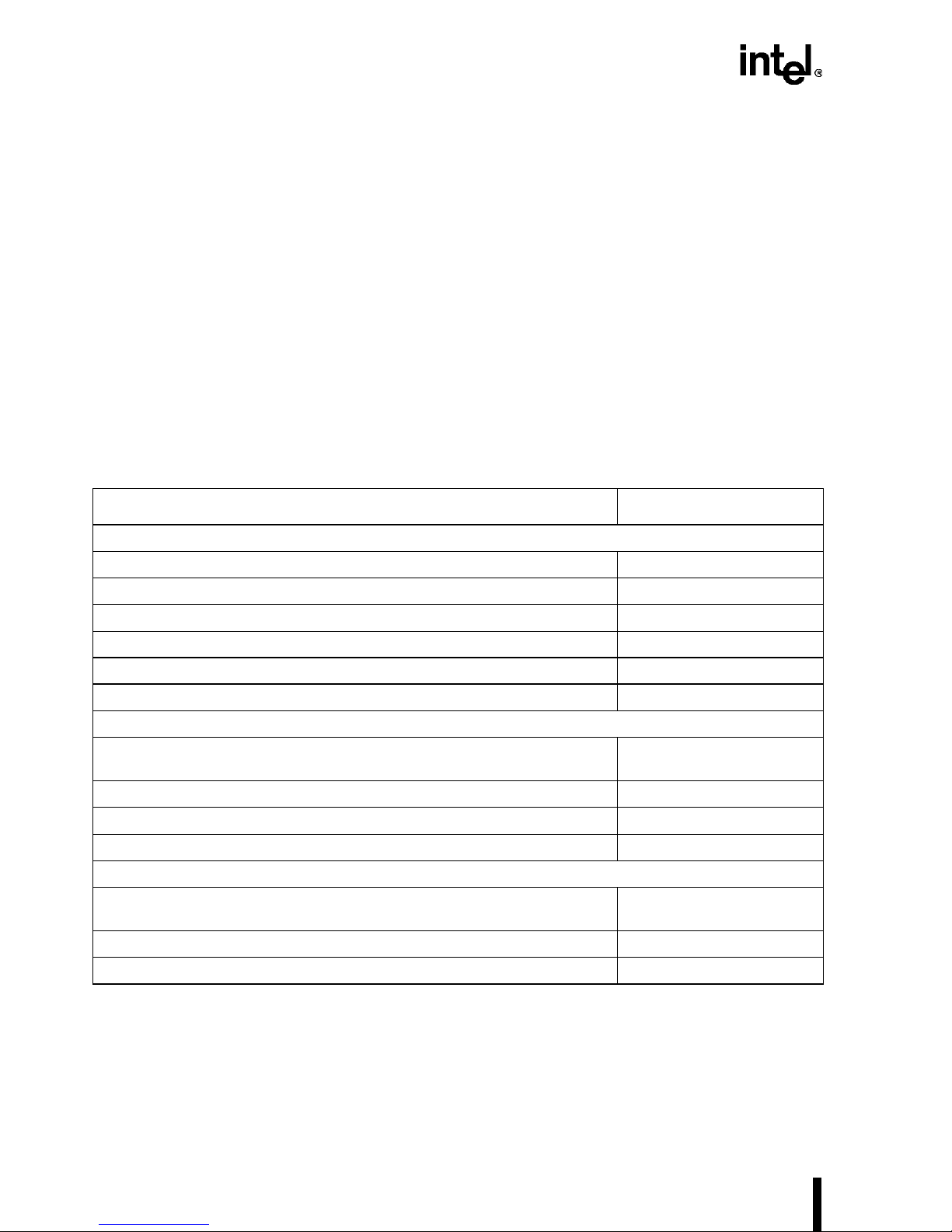
1.6.1 Related Documents
The following Intel documents contain additional information on designing systems that incorporate the Intel 486 processors.
Intel Document Name Intel Order Number
Datasheets
Embedded Intel486™ SX Processor
Embedded IntelDX2™ Processor
Embedd ed Ultra-L ow Power Inte l4 86 ™ S X Pr oc es s or
Embedded Ultra Low-Power Intel486™ GX Processor
Embedded Write-Back Enhanced IntelDX4™ Processor
MultiProcessor Specification
Intel Architecture Software Deve loper's Manual
Embedded Intel486™ Process or Family Develo per’s Manual
Ultra-Low Power Int el486™ SX Processor Evaluation Board Manual
Intel486™ Processor Family Programmer’s Reference Manual
AP-505–Picking Up the Pace: Designing the IntelDX4™ Processor into
Intel486™ Processo r-Base d Designs
Intel486™ Microp rocess or Performa nc e Brief
IntelDX4™ Processor Performance Brief
datasheet 272769-001
datasheet 272770-001
datas heet 27273 1- 0 01
datasheet 272755-001
datasheet 272771-001
Manuals
, Volu mes 1 and 2 243190-001
Application Notes/Performance Briefs
242016-005
243191-001
273021.001
272815-001
240486-003
242034-001
241254-002
242446-001
1-6
Page 25
GUIDE TO THIS MANUAL
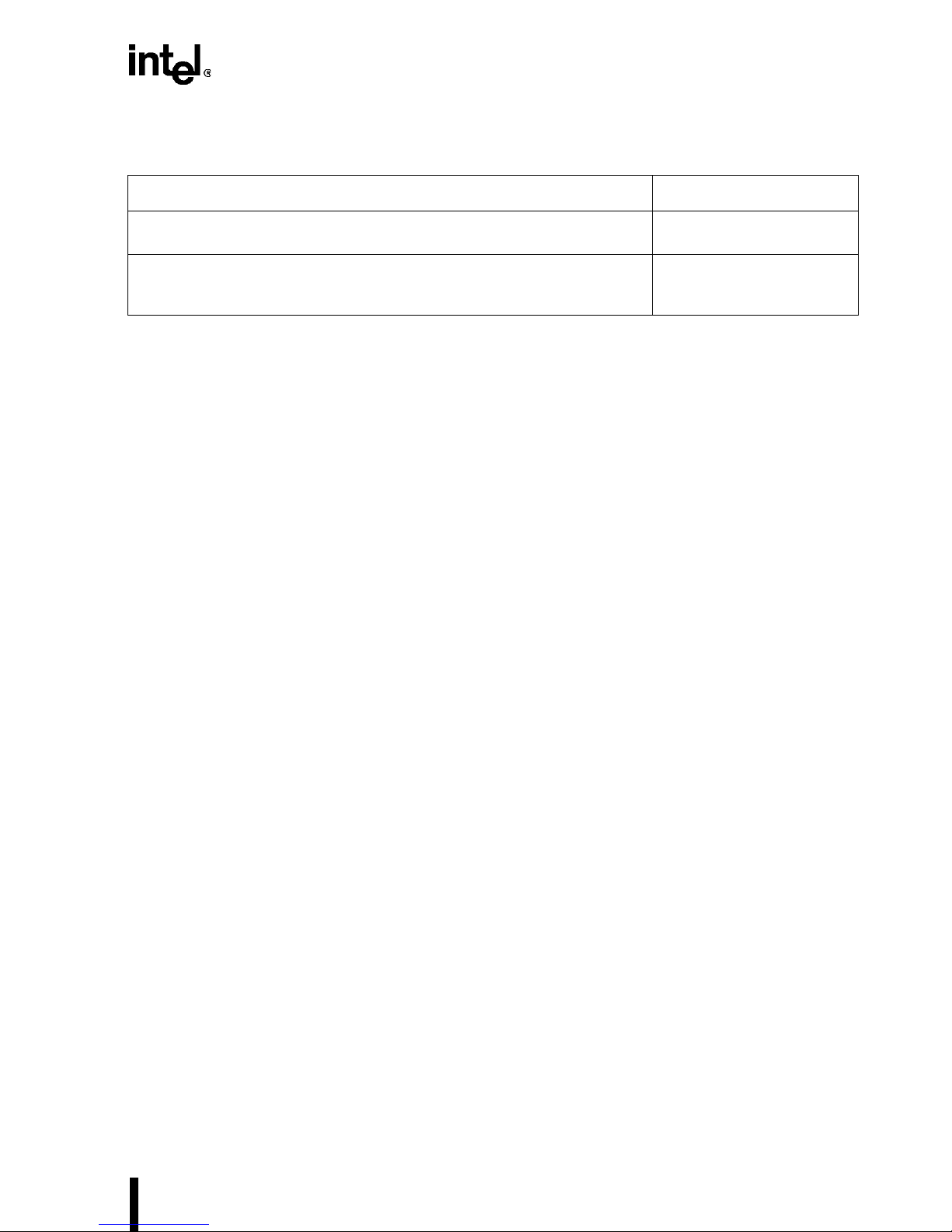
You can obtain the following resources from the Word Wide Web at the s ites listed.
Document Name Web Site
Standard 1149.1—1990, IEEE Standard Test Access Port and BoundaryScan Architecture
PCI Loc al B us Spe ci fic ation
and its supplement,
, Revi sions 2.0 and 2.1 Contact the PCI Specia l
Standard 1149.1a—1993
Contact the IEEE at
http://www.ieee.org.
Interest Group at
http://www.pcisig.com
1-7
Page 26

Page 27

Introduction
Chapter Contents
2.1 Processor Features.................................................................2-2
2.2 Intel486™ Processor Product Family................ ...................2-4
2.3 System Component s............................................ ......... ........ .2-7
2
2.4 System Architecture..............................................................2-7
2.5 Systems Applications..........................................................2-11
Page 28

Page 29

CHAPTER 2
INTRODUCTION
The Intel486™ processor family enables a range of low-cost, high-performance embedded system designs cap able of runni ng the e ntire i nstalle d base o f DOS *, Win dows*, OS/2 *, and UNIX*
applications written for the Intel architecture. This family includes the following processors:
•The IntelDX4™ processor is the fastest Intel486 processor (up to 50% faste r than an
IntelDX2™ processor). The IntelDX4 processor int egrates a 16-Kbyte unifie d ca che and
floating-poi nt hardware on-chip for improved performance.
The IntelDX4 processor is also available with a write-back on-chip cache for improved
entry-level performance.
•The IntelDX2™ processor integrates an 8-Kbyte unified cache and floating-point
hardware on-chip.
The IntelDX4 and IntelDX2 processors use Intel’s speed-multiplying technology, allowing
the p roc es sor core to op erate at fre q u en c ie s hi g h er th an th e ex t er n al m emory bus .
• Th e Int el486 SX processor offers the features of the IntelDX2 processor without floating-
point hardware and clock multiplying.
•The Ultra-Low Power Ultra-Low Power Intel486 SX and Ultra-Low Power
Intel486 GX processors provide additional power-saving features for use in batteryoperated and hand-held embedded designs . Th e Ultra-Low Power Intel486 SX processor,
like the other Intel486 processors, supports dynamic data bus sizing for 8-, 16-, or 32-bit
bus sizes, whereas the Ultra-Low Power Intel486 GX processor has a 16-bit external data
bus.
The entire Intel486 processor family incorporates energy efficient “SL Technology” for mobile
and fixed embedded comput ing . SL Tec hnol ogy ena bles syste m de signs t hat exceed th e Envi ronmental Protection Agency’s (EPA) Energy Star program guidelines without compromising performance. It also increases system design flexibility and improves battery life in all Intel486
processor-bas ed hand-held applications. S L Technology allows system de signers to di fferentiate
their power management schemes with a variety of energy efficient, battery life enhancing features.
Intel486 processors provide power management features that are transparent to application and
operating system software. Stop Clock, Auto HALT Power Down, and Auto Idle Power Down
allow software-transpare nt co ntrol over processor power management.
Equally important is the capability of the processor to manage system power consumption.
Intel486 processor System Management Mode (SMM) incorporates a non-maskable System
Management Interrupt (SMI#), a corresponding Resume (RSM) instruction and a new memory
space for sys tem m anage ment code. Althou gh t ran sparent to an y appl icati on or opera ti ng sy stem,
Intel's SMM ensures seamless power control of the processor core, system logic, main memory,
and one or more peripheral devices.
2-1
Page 30

EMBEDDED Intel486™ PROCESSOR HARDWARE REFERENCE MANUAL
Intel486 p rocessors are availa ble in a f ull range o f speeds (16 MHz to 100 MHz), package s (PGA,
SQFP, PQFP, TQFP), and voltages (5 V, 3.3 V, 3.0 V and 2.0 V) to meet many system design
requirements.
2.1 PROCESSOR FEATURES
All Intel 486 processors consist of a 32-bit int eger processing unit, an on -chip cache, and a memory management unit. Th ese ensure full binary compa ti bility with t he 8086, 808 8, 80 186, 80286,
Intel386™ SX, and Intel386 DX processors, and with all versions of Intel486 processors. All
Intel486 processors offer the following features:
• 32-bit RISC integer core — The Intel486 processor performs a complete set of arithmetic
and logical operations on 8-, 16-, and 32-bit data types using a full-width ALU and eight
general pur pose registers.
• Single Cycle Execution — Many instructions exec u te in a single clock cycle.
• Instruction Pipelining — The fet ching, decoding, address translation, and execution of
instructions are overlapped within the Intel486 processor.
• On-Chip Floating-Point Unit — The IntelDX2 and Intel DX4 processors support the 32-,
64-, and 80-bit formats sp ecified in IEEE standard 754. The unit is binary compatible wit h
®
the 8087, Intel287, and Intel387 coprocessors, and with the Intel OverDrive
processor.
• On-Chip Cache wi th Cach e Cons iste ncy Sup port — An 8-Kbyt e (16-Kbyt e on the Int elDX4
processor) int ern al ca che is u sed fo r bot h da ta and inst ru ction s. Ca che hi ts pro vide zero wait
state access times for data within the cache. Bus activity is tracked to det ect alterations in
the memory repre sented by the internal cach e. The internal cache can be in v alidated or
flushed so that an ex ternal cache controller can maintain ca che cons istency.
• External Cache Cont rol — Writ e- ba ck an d fl us h c ontr o ls fo r an ext er nal ca ch e a re pro vi de d
so the proces sor can maintain cach e consistency.
• On-Chip Memory Management Unit — Add ress m anagement a nd memory s pace protec tio n
mechanisms maintain the integrity of memory in a multi-tasking and virtual memory
environment. The memory management unit supports both segmentatio n and paging.
• Burst Cycles — Burst transfers all ow a new doubl eword to be read from memory on each
bus clock cycle. This capability is especially useful for instruction prefetch and for filling
the internal cache.
• Write Buffers — The processor contains four write buffers to enhance the performance of
consecuti ve writes to memory. The processor can continue internal operations after a write
to these buffers, without waiting for the write to be completed on the external bus.
• Bus Backoff — If another bus master nee ds c ontrol of the bus during a process or-initiated
bus cyc le, the In tel486 processo r floats its bus sign als, then restarts the cy cle when th e b u s
becomes avai lable again.
• Instructi on Restart — Programs can continue execution following an exception that is
generated by an uns uccessful at tempt to access memory. This feature is important for
supporti ng demand-paged virtual memory applications.
2-2
Page 31

INTRODUCTION
• Dynamic Bus Sizing — External controllers ca n dynamically alter the effective width of the
data bus. Bu s widths of 8, 16, or 32 bits c an be used (the 8-bit and 32-bit bus widths a re not
available on the Ultra-Low Power Intel486 GX processor).
• Boundary Scan (JTAG) — Boundary Scan provides in-circuit tes ting of components on
printed circuit boards. The Intel Boundary Scan implementation conforms with the IEEE
Standard Test Access Po rt and Boundary Scan Architec ture.
SL Technology provides the following features:
• Intel System Management Mode — A unique Intel architecture operating mode provides a
dedicated special purpose interrupt and address space that ca n be us ed to implement
intelligent power manag em ent and other enhanced functions in a manner that is comple tely
transparent to the operating system and applications software.
• I/O Restart — An I/O instruction interrupted by a System Man age me nt Interrupt (SMI#)
can automatically be restarted following the execution of the RSM instruction.
• Stop Clock — The Intel 486 proc essor ha s a stop c lock con trol mecha nism tha t provi des two
low-power states: a “f as t wake-up” St op Grant state and a “slow wake-up” Stop Clock state
with CLK frequency at 0 MHz.
• Auto HALT Power Down — After the execution of a HALT instruction, the Intel486
processor issues a normal Halt bus cycle and the clock input to the Int el486 processor core
is automatically stopped, causing the processor to enter the Auto HALT Power Down state.
• Upgrade Power Down Mode — When an Intel486 processor upgrade is installed, the
Upgrade Power Down Mode detects the prese nce of the upgrade, powers down the core,
and three-states all outputs of the original processor, so t he Intel486 processor enters a very
low current mode.
• Auto Idle Power Down — This function allows the processor to reduce the core frequency
to the bus frequency when both the core and bus are idle. Auto Idle Power Down is
software-transparent and does not affect processor performance. Auto Idle Po wer Down
provides an avera ge power savings of 10% and is only applicable to clock-multiplied
processors.
Enhanced Bus Mode Features (for the Write-Back Enhanced Intel DX4 processor only):
• Write Back Internal Cache — The Write-Bac k Enhanced IntelDX4 proces sor adds write-
back support to the unified cache. The on-chip cac he is configurable to be write - back or
write-through on a line-by-line basis. The internal cache implements a modified MESI
protocol, which is most applicable to single processor systems.
• Enhanced Bus Mode — The definitions of some signals have been changed to support the
new Enhanced Bus Mode (Write-Back Mode).
• Write Bursting — Data written from the proces s or to memo ry can be burst to provide zero
wait state transfers.
2-3
Page 32

EMBEDDED Intel486™ PROCESSOR HARDWARE REFERENCE MANUAL
2.2 Intel486™ PROCESSOR PRODUCT FAMILY
Table 2-1 shows the I ntel48 6 proces sors available by clock mode, suppl y volt age, maximum fre-
quency, and package. An individual product has either a 5 V supply voltage or a 3.3 V supply
voltage, but not both. Likewis e, an individual product may have 1x, 2x, or 3x clock. Please contact Intel for the latest product availability and specifications.
Table 2-1. Product Opti ons
Intel486™ Processor
1x Clock
Intel486 SX
Processor
Ultra-Low Power
Intel48 6 SX
Processor
Ultra-Low Power
Intel48 6 GX
Processor
2x Clock
IntelDX2™ Processor
3x Clock
V
CC
V
CCP
3.3 V ✓✓ ✓
5V ✓✓ ✓ ✓
2.4-3.3 ✓✓
2.7-3.3 ✓✓
2.0-3.3 ✓✓
2.2-3.3 ✓✓
2.4-3.3 ✓✓
2.7-3.3 ✓✓
3.3 ✓✓
16 20 25 33 40 50 66 75 100
5 ✓✓ ✓
Processor
Frequency (MHz)
168-
Pin
PGA
208-
Lead
SQFP
196-
Lead
PQFP
176-
Lead
TQFP
Write- B ac k Enha nc ed
IntelDX4™ Processor
2-4
3.3 ✓✓ ✓ ✓
Page 33

INTRODUCTION
2.2.1 Operating Modes an d Co m p a tib il i ty
The Intel486 p rocessor can ru n in modes t hat give it object-co de compatibi lity with software written for the 8086, 80286, and Intel386 processor families. The operating mode is set in software
as one of the fo llowing:
• Real Mode: When the processor is powered up or reset, it is initialized in Real Mode. This
mode has the same base architecture as the 8086 processor but allows access to the 32-bit
register set of the Intel486 processor. The address mec hanism, maximum memory size
(1 Mbyte), and interrup t handling are identic al to the Real Mode of the 80286 process or.
Nearly all Intel486 processor instructions are available, but the default operand size is 16
bits; in order to us e the 32-bit regist ers and addressing modes, override instruc tion prefixes
must be used. The primary purpose of Real Mode is to set up the processor for Protected
Mode operation.
• Protected Mode (als o call ed Prot ected Virtua l Addre ss Mode): The compl et e capabili ti es of
the Intel486 processor become available when programs are run in Prot ec ted Mode. In
addition to segm entation protection, paging can be us ed in Protected Mode. The linear
address space is four gigabytes and virtual memory programs of up to 64 terabytes can be
run. All existing 8086, 80286, and Intel386 processor software can be run under the
Intel486 processor’s hardware-assisted protection mechanism. The addressing mechanism
is more sophisticated in Protected Mode than in Real Mode.
• Virtual 8086 Mode, a sub-mode of Protected Mode, allows 8086 programs to be run with
the segmentation and paging protect ion mechanisms of Protected Mode. This mode offers
more flexibili ty than the Real Mode for running 8086 pr ograms. Using this mode, the
Intel486 processor can execute 8086 operating systems and applications simultaneously
with an Intel486 operating system and both 80286 and Intel486 processor applications.
The hardware offers additional modes, which are described in greater detail in the Embedde d
Intel486™ Processor Family Developer’s Manual.
2.2.2 Memory Management
The memory management unit supports both segmentation and paging. Segmentation provides
several independ ent, prot ecte d addr ess spaces . This s ecurit y feature limit s the damage a program
error can cause. For example, a program’s stack space should be preve nted from growing into its
code space. The segmentation unit maps the separate address spaces seen by programmers into
one unsegmented, linear address space.
Paging provide s access t o data struct ures larger t han the ava ilable me mory space by kee ping them
partly in memory and part ly on disk. Pagin g breaks the li near addres s space into units of 4 Kbytes
called pages . When a program m akes i ts fi rst r eferen ce to a page, the pr ogram can be s topped, the
new page copied from disk, and the program restart ed. Programs tend to use only a few pages at
a time, so a processor with paging can simulate a large address space in RAM using a small
amount of RAM plus storage on a disk.
2-5
Page 34

EMBEDDED Intel486™ PROCESSOR HARDWARE REFERENCE MANUAL
2.2.3 On-chip Cache
A software-transparent 8-Kbyte cache (16-Kbyte on the IntelDX4 processor) stores recently accessed information on the processor. Both instructions and data can be cached. If the processor
needs to rea d data t hat is avail abl e in the cache , the c ache re sponds, the reby avoidin g a ti me-consuming external memory cycle. This allows the processor to complete transfers faster and reduces
traffic on the processor bus.
The internal cache on all members of the Intel 486 processor fami ly uses a write-th rough protoc ol.
The IntelDX4 proc essor can also be con figured t o implement a write -back protocol. With a writethrough protocol, all writes to the cache are immediately writt en to the external me mory that the
cache represents. With a write-back protocol, writes to the cache are stored for future memory
updating. To reduce the impact of writes on performance, the processor can buffer its write cycles; an operation that writes data to memory can finish before the write cycle is actually performed on the processor bus.
The pro cesso r perfo rms a c ache li ne fill to place n ew inf ormat ion int o the o n-chip cache . This
operation reads four doublewords into a cache line, the smallest unit of storage that can be allocated in the cache. Most read cycles on the processor bus result from cache misse s, which cause
cache line fills.
The Intel486 processor provides mechanisms to maintain cache consistency between memory
and cached data in multiple bus master environments. These mechanisms protect the Intel486
processor from reading invalid data from its own internal cache or from external caches . For example, when the Intel 486 pro cessor att empts to read an operan d from memory that is also held in
the cache of another bus master, the other bus master is forced to write its cached data back to
memory before t he Intel486 processor can complete its read from memory. This is done bec ause
the cached versi on of t he dat a may have been up dated, an d so may no w be diffe rent from the ve rsion stored in memory .
Most memo ry sys te ms op ti mize t he sp ee d of ac ce s s on a re ad cy cle . Th is i s bec au se t he la rg e ma jority o f al l m e m o ry access es in a typical sy st em are re ad a ccesses . Th e Intel 4 8 6 p ro c e ss o r’s internal cache changes this ratio. Most read requests result in cache hits, so most memory accesses
on the processor bus are write cycles. Memory optimization should be done with this in mind.
2.2.4 Floating-Poin t Unit
The internal floating-point unit performs floating-point operations on the 32-, 64- and 80-bit
arithmetic formats as specified in IEEE Standard 754. Like the i nteger processing unit, the floating-point unit architecture is binary-compatible with the 8087 and 80287 coprocessors. The architecture is 100% compatible with the Intel387 DX and Intel387 SX coprocessors.
Floating-point instructions execute fastest when they are entirely internal to the processor. This
occurs when all operands are in the internal registers or cache. When data needs to be read from
or written to external locations, burst transfers minimize the time required and a bus locking
mechanism ensures that the bus is not relinquished to other bus masters during the transfer. Bus
signals are provided to monitor errors in floating-point operations and to control the processor’s
response to such errors.
2-6
Page 35

2.2.5 Upgrade Power Down Mo de
INTRODUCTION
Upgrade Power Down Mode on the Intel486 processor is initiated by the Intel OverDrive
®
pro-
cessor using the UP# (Upgrade Present) pin. Upon sensing the presence of the Intel OverDrive
Processor, the Intel486 processor three-states its outputs and enters the “Upgrade Power Down
Mode,” lowering its power consumption. The UP# pin of the Intel486 processor is driven active
(low) by the UP# pi n of t he Inte l OverDriv e pr ocessor. (I n the embedd ed Inte l486 proc essor fa mily, the UP# pin has been renamed Reserved, with no changes in functionality.)
2.3 SYSTEM COMPONENTS
Intel offers several chips that are highly compatible with the Intel486 processor. These components can be used to design high-performance embedded systems with a minimum of effort and
cost. For components not directly connectable to the Intel486 processor bus, industry-standard
interfaces can be used.
The Intel486 processor provides all integer and floating-point CPU functions plus many of the
peripheral functions required in a typical computer system. It executes the complete instruction
set of the Intel38 6 pr ocessor and Intel387 DX numerics coprocessor, with s om e extensions. The
proce sso r eli min ates t he n eed for an e xtern al m emor y m anag eme nt u nit, a nd th e on -chi p ca che
mini mi zes the need for ext er n al cac h e an d ass o ci at ed co n tro l log i c.
The remaining chapters of this manual detail the Intel486 processor’s architecture, hardware
functions, and interfacing. For more information on the architecture and software interface, see
the Embedded In tel 486™ Processor Family Devel oper’s Manual an d th e In te l Arc hite ctu re Sof t-
ware Developer’ s Manual, Volumes 1 and 2.
2.4 SYSTEM ARCHITECTURE
The Intel486 processor can be the foundation for single-processor or multi-processor embedded
systems. A singl e-processor s ystem might be a n embedded persona l computer des igned to use t he
Intel486 processor. A system design of this type offers higher performance through the integration of floating-point processing, memory management, and caching. More complex embedded
systems may use multiple processors that provide, at chip-level, the equivalent of board-level
functions. Designs of this type are typic ally used in multi-user machines , scientific workstations,
and engineering works tations.
A typical Intel486 design is shown in Figure 2-1. This example uses a single Intel486 processor
with external cache. Other examples of system design are illustrated in the figures that follow.
2-7
Page 36

EMBEDDED Intel486™ PROCESSOR HARDWARE REFERENCE MANUAL
Intel486™
Process or
Processor Bus
External Cache
Optional
Memory
Figure 2-1. A Typical Intel486™ Processor System
2.4.1 Single Processor System
System Bus
Bus
Controller
External Bus
Bus
Processor
LAN
Coprocessor
In single-processor system s, the processor handles all peri pheral resources a nd intelligen t devices, and executes all software. The Intel486 processor does this in a more efficient way and for a
wider range of task c omplexity tha n earli er processors . Singl e-pr ocesso r systems of fer small s ize
and low cost in exchange for flexibility in upgrading or expanding the system. Typical applications include personal computers, small desktop workstations, and embedded controllers. Such
applications are implemented as a single board, usually called a motherboard; the processor bus
does not extend beyond the board occupied by the Intel486 processor.
Figure 2-2 shows an ex ampl e of such a sys tem. I n a si ng le- proc essor syst e m, de v ices that shar e
the pr ocessor bus must be selected carefull y. All co mponents must interact directly with the processor bus or ha ve interface logic tha t allows them to d o so. The tota l bus bandwi dth requirem ents
2-8
Page 37

INTRODUCTION
of other componen ts should be no more than 50% of th e available processor-bu s bandwidth. Traffic above 50% degrades performance of the processor.
Intel486™
Processor
Peripheral
Controller
Memory
Level-2
Cache
Processor Bus
DMA
Controller
Figure 2-2. Single -Processor System
Two basic design approaches are used to ela borate the single-processor s ys tem into a more complex system. The first approach is to add more devic es to the process or bus. This can be don e up
to the limit mentioned above: no more than 50% of the processor-bus bandwidth should be used
by devices other than the Intel486 processor. The second design approach is to add more buses
to the system. By addi ng buses, greate r bus bandwidt h is crea ted in the syste m as a whole, which
in turn allows more devices to be added to the system. The two approaches go hand-in-hand to
expand the capabilities of a system. The sections below give only a few examples of the great
variety of designs that are possible with Intel486 processor-compatible devices.
2.4.2 Loosely Coupled Multi-Processor System
Loosely coupled multi-processor systems include board-level products that communicate with
one another through a standard system bus. In this architecture, each board contains a processor
and associated logic. There is typically only one processor per board. Components within each
board communicat e on eit her a processor bu s or on the buff ered s yste m bus. The s yste m bus usually provides extr a bandwidth beyond the processor bus.
A typical system is show n in Figure 2-3. Such system-bus boards typically occur in higher-end
personal computers and embedded systems that allow for modular expansion. A typical design
would include a c oprocessor or LAN interf ace board in a personal computer, or a network-interface board in a file server or gateway. Systems built from thes e boa rds can contain a mix of processor types. Devices attached to the processor bus on a given board make demands that may
affect system performance . For example, a typical sys tem may use up to 3% of the bus bandwidth
to handle 10-Mbit/second Ethernet traffic.
2-9
Page 38

EMBEDDED Intel486™ PROCESSOR HARDWARE REFERENCE MANUAL
I/O
Intel486™
Processor
Processor Bus
Bus
Controller
Memory
Memory
System Bus
Intel486™
Processor
Processor Bus
Bus
Controller
I/O
Figure 2-3. Loose ly Coupl ed M ulti-processor System
2.4.3 External Cache
External cache allows a system to achieve maximum performance. This cache is essential in
tightly c oupled multi-pr ocesso r embedded system s. The external cache consi sts of cache memory
(usually fast SRAM) and cac he co ntrol logic.
External c ache systems typic al ly provi de acces s to the c ache from bot h t he proc essor a nd the s ystem buses. This is shown in Figure 2-4. These caches typically monitor processor memory accesses, processor acce ss time, and consistency between cache and memory. The cache controller
is responsible for maintaining an optimal mix of data and instructions in cache.
2-10
Page 39

External
Cache
Controller
i486™
Intel486™
Processor
Processor
Processor Bus
SRAM
System Bus
INTRODUCTION
DRAM
Controller
DRAM
Array
A5131-01
Figure 2-4. External Cache
2.5 SYSTEMS APPLICATIONS
Most Intel486 processor systems can be grouped as one of these types:
• Embedded Personal Computer
• Embedded Controller
Each type of system has distinct design goals and constraints, as described in the following sections. Software runn ing on th e process or, even in stand-al one embedde d applic at ions, sho uld use
a standard operating system such as DOS *, Windows 95*, Windows NT*, OS/2*, or UNIX Sy stem V/386*, to faci litate debuggi ng, documentation, and transporta bility.
2-11
Page 40

EMBEDDED Intel486™ PROCESSOR HARDWARE REFERENCE MANUAL
2.5.1 Embedded Personal Computers
In single-processor embedded systems, the processor interacts directly with I/O devices and
DRAM memory. Other bus masters such as a LAN coprocessor typically reside on the system
bus; conventional personal computer architecture puts most peripherals on separate plug-in
boards. Expansion is typically limited to memory boards and I/O boards. A standard I/O architecture such as MCA or EISA is used. Syste m cost and siz e are ve ry important . Figu re 2-5 shows
an example of an embedde d personal computer or an embedd ed con troller application.
Optional Local
Level-2 Cache
Intel486™
Processor
Processor Bus
Local
Peripheral
Controller
System Bus
“Slow”
Memory
Memory
Bus
Controller
Other
Peripheral
Figure 2-5. Embedded Personal Computer and Embedded Controller Example
External cache is optional in such envir onments, particular ly if system perfor ma n ce is not a critical p aramet er. Wh ere an e xter nal ca che is u sed, m emory- acces s spee ds im prove only if the ca che
is desig n ed as a w rite-bac k sys t em and me mo r y access has zero to on e wa it states.
2.5.2 Embedded Controllers
Most embedded controllers perform real-time tasks. The performance of the Intel486 processor
and its compat ibility wi th the exte nsive inst alled base of Intel386 pro cessors a re important fa ctors
in its choic e. Embedde d controlle rs are us ually imple mented as s tand-alon e systems, with less e x-
2-12
Page 41

INTRODUCTION
pansion capability than other applications because they are tailored specifically to a single environment.
If code must be stored in EPROM, ROM, or Flash for non-volatility, but performance is also a
critical issue, then the code should be copied into RAM provided specifically for this purpose.
Frequently used routines and variables, such as interrupt handlers and interrupt stacks, can be
locked in the proc essor’s inte rnal cache so they are always av ailable quickly.
Embedded controll er s usuall y requir e le ss me mory than ot her applic ations , an d control progr ams
are usually tightly written machine-level routines that need optimal performance in a limi ted variety of tasks. The processor typically interacts directly with I/O devices and DRAM memory.
Other peripherals connect to the system bus.
2-13
Page 42

Page 43

Internal Architecture
Chapter Contents
3.1 Instru ctio n Pi pe li n in g. ........ .. ....... ... .. ....... ... ....... ... ....... .. ........3-6
3.2 Bus Interface Unit .................................................................3-7
3.3 Cache Unit...........................................................................3-10
3
3.4 Instruction Prefetch unit......................................................3-13
3.5 Instruction Decode Unit ......................................................3-14
3.6 Contr o l U n it ........ .. ........ .. ....... ... ....... ... ....... .. ........ .. ... ....... .. .3-1 4
3.7 Integer (Datapath) Unit .......................................................3-14
3.8 Floating-Point Unit .............................................................3-15
3.9 Segmentation Unit...............................................................3-15
3.10 Paging Unit .........................................................................3-16
Page 44

Page 45

CHAPTER 3
INTERNAL ARCHITECTURE
The Intel486™ SX processor has a 32-bit architecture with on-chip memory management and
leve l- 1 ca ch e.
The IntelDX2™ and IntelDX4™ processors also have a 32-bit architec ture with on-chi p memory
management and cache, but add clock multiplier and floating-point units. The Intel486 SX and
Intel486 DX processors support dynamic bus sizing for the ext ernal data bus; that is, the bus size
can be specified as 8-, 16-, or 32-bi ts wide.
Internally, the ultra-low power processors are similar to the Intel486 SX processor, but add a
clock control unit. Althou gh the Ultra-Low Powe r Intel486 SX supports d ynam ic bus sizing, the
Ultra-Low Power Intel486 GX supports only a 16-bit external data bus. The Ultra-Low Power
Intel486 GX also has advanced power management features.
Table 3-1 lis ts the functional units of the embedded Int el486 processors.
Table 3-1. Intel486™ Processor Family Functi onal Units
Ultra-Low Power
Functional Unit
IntelDX2™ and
IntelDX4™ Processors
Intel486™ SX
Processor
Intel486 SX and
Ultra-Low Power
Intel486 GX Proc es so rs
Bus Interface ✓✓✓
Cache (L1) ✓✓✓
Instruction Prefetch ✓✓✓
Instruction Decode ✓✓✓
Control ✓✓✓
Integer and Datapath ✓✓✓
Segmentation ✓✓✓
Paging ✓✓✓
Floating-Point ✓
Cloc k Mu ltiplie r ✓
Clock Control ✓
Figure 3-1 is a block diagram of the embedded IntelDX2 and Inte lDX4 processors. Note that the
cache unit is 8-Kbytes for the IntelDX2 processor and 16 Kbytes for the IntelDX4 processor.
Figure 3-2 is a block diagram of the embedded Intel486 SX processor and Figure 3-3 is a block
diagram of the Ultra-Lo w P ower Intel486 SX and the Ultra-Low Power Intel486 GX processors.
3-1
Page 46

EMBEDDED Intel486™ PROCESSOR HARDWARE REFERENCE MANUAL
64-Bit Interunit Transfer Bus
Core
Clock
32
32
32
Clock
Multiplier
Bus Interface
Address
Drivers
Write Buffers
4 x 32
Data Bus
Transceivers
Barrel
Shifter
Register
File
ALU
Base/
Index
Bus
32
Segmentation
Unit
Descriptor
Registers
Limit and
Attribute PLA
32-Bit Data Bus
32-Bit Data Bus
Linear Address
Paging
Unit
Translation
Lookaside
Buffer
32
PCD
PWT
2
20
Physical
Address
Cache Unit
8 Kbyte Cache
(DX2)
16 Kbyte Cache
(DX4)
CLK
A31-A2
BE3#- BE0#
D31-D0
128
Bus Control
Displacement Bus
Micro-
Instruction
32
Prefetcher
Sequencer
32-Byte Code
Queue
2x16 Bytes
Floating
Point Unit
Floating
Point
Register File
Control &
Protection
Test Unit
Control
ROM
Decoded
Instruction
Path
Instruction
Decode
Code
Stream
24
Generation
and Control
Figure 3-1. IntelDX2™ and IntelDX4™ Processors Block Diagram
Request
Burst Bus
Control
Bus Size
Control
Cache
Control
Parity
Boundary
Scan
Control
ADS# W/R# D/C# M/IO#
PCD PWT RDY# LOCK#
PLOCK# BOFF# A20M#
BREQ HOLD HLDA
RESET SRESET INTR
NMI SMI# SMIACT#
FERR# IGNNE#
STPCLK#
BRDY# BLAST#
BS16# BS8#
KEN# FLUSH#
AHOLD EADS#
DP3-DP0 PCHK#
TCK TMS
TDI TD0
A5439-01
3-2
Page 47

Barrel
Shifter
Register
File
ALU
Base/
Index
Bus
32
64-Bit Interunit Transfer Bus
32-Bit Data Bus
32-Bit Data Bus
Linear Address
Segmentation
Unit
Descriptor
Registers
Limit and
Attribute PLA
Paging
Unit
Translation
Lookaside
Buffer
32
PCD
PWT
2
20
Physical
Address
Cache Unit
8 Kbyte
Cache
INTERNAL ARCHITECTURE
32
32
32
Bus Interface
Address
Drivers
Write Buffers
4 x 32
Data Bus
Transceivers
A31-A2
BE3#- BE0#
D31-D0
Micro-
Instruction
128
Displacement Bus
32
Prefetcher
32-Byte Code
Queue
2x16 Bytes
Control &
Protection
Test Unit
Control
ROM
Decoded
Instruction
Path
Instruction
Decode
Code
Stream
24
Figure 3-2. Intel486™ SX Processor Block Diagram
Bus Control
Request
Sequencer
Burst Bus
Control
Bus Size
Control
Cache
Control
Parity
Generation
and Control
Boundary
Scan
Control
ADS# W/R# D/C# M/IO#
PCD PWT RDY# LOCK#
PLOCK# BOFF# A20M#
BREQ HOLD HLDA
RESET SRESET INTR
NMI SMI# SMIACT#
FERR# IGNNE#
STPCLK#
BRDY# BLAST#
BS16# BS8#
KEN# FLUSH#
AHOLD EADS#
DP3-DP0 PCHK#
TCK TMS
TDI TD0
A5443-01
3-3
Page 48

EMBEDDED Intel486™ PROCESSOR HARDWARE REFERENCE MANUAL
64-Bit Interunit Transfer Bus
Core
Clock
32
32
32
Clock
Control
Bus Interface
Address
Drivers
Write Buffers
4 x 32
Data Bus
Transceivers
Barrel
Shifter
Register
File
ALU
Base/
Index
Bus
32
Segmentation
Unit
Descriptor
Registers
Limit and
Attribute PLA
32-Bit Data Bus
32-Bit Data Bus
Linear Address
Paging
Unit
Translation
Lookaside
Buffer
32
PCD
PWT
2
20
Physical
Address
Cache Unit
8 Kbyte
Cache
CLK
A31-A2
BE3#- BE0#
D31-D0 on ULP486™ SX
D15-D0 on ULP486™ GX
ADS# W/R# D/C# M/IO#
PCD PWT RDY# LOCK#
PLOCK# BOFF# A20M#
BREQ HOLD HLDA
RESET SRESET INTR
NMI SMI# SMIACT#
FERR# IGNNE#
STPCLK#
BRDY# BLAST#
BS16# BS8# (not present
on ULP486 GX)
KEN# FLUSH#
AHOLD EADS#
DP3-DP0 PCHK# on
ULP486 SX
DP1-DP0 PCHK# on
ULP486 GX
TCK TMS
TDI TD0
A5440-01
Micro-
Instruction
Control &
Protection
Test Unit
Control
ROM
Displacement Bus
Decoded
Instruction
Path
Instruction
Decode
32
Code
Stream
24
128
Prefetcher
32-Byte Code
Queue
2x16 Bytes
Bus Control
Request
Sequencer
Burst Bus
Control
Bus Size
Control (on
ULP486 SX
only)
Cache
Control
Parity
Generation
and Control
Boundary
Scan
Control
Figure 3-3. Ultr a-Low Power Intel486™ SX and Ultra-Low Power Int el486 GX Processors
Block Diagram
Signals from the external 32-bit processor bus reach the internal units through the bus interface
unit. On the internal side, the bus interface unit and cache unit pass addresses bi-directionally
through a 32-bit bus. Data is pas sed from the cache to the bus int erface unit on a 32-bit data bus.
The closely coupled cache and instruction prefetch units simultaneously receive instruction
prefetches from the bus interface unit over a shared 32-bit data bus, which the cache also uses to
receive operands and other types of data. Instructions in the cache are accessible to the instruction
prefetch unit, which contains a 32-byte queue of instructions waiting to be executed.
The on-chip cache is 16 Kbytes for the IntelDX4 processor and 8 Kbytes for all other members
of the Intel486 processor family. It is 4-way set associative and follows a write-through policy.
The Write-Ba ck Enhanced Int elDX4 proc essor ca n be se t t o use an on- chi p write -back c a che pol -
3-4
Page 49

INTERNAL ARCHITECTURE
icy. The on-chip cache includes features to provide flexibility in external memory system design.
Individual pages can be designated as ca che able or non-cachea ble by software or hardware. The
cache can also be enabled and disabled by software or hardware.
Internal cache memory allows frequently used data and code to be stored on-chip, reducing accesses to the external bus. RISC design techniques reduce instruction cycle times. A burst bus
feature enables fast cache fills.
When internal requests for data or instructions can be satisfied from the cache, time-consuming
cycles on the exte rnal proc essor bus are av oided. The bus inte rface unit is only invol ved whe n an
operation needs access to the processor bus. Many internal operations are therefore transparent
to the external system.
The instruction decode unit translates instructions into low-level control signals and microcode
entry points. The control unit executes microcode and controls the integer, floating-point, and
segmentation units. Computation results are placed in internal registers within the integer or
floating-point units, or in the cache. Internal storage locations (datapaths) are kept in the integer
unit.
The cache shares two 32-bit data buses with the segmentation, integer, and floating-point units.
These two buses can be used together as a 64-bit inter-unit transfer bus. When 64-bit segment
descriptors are passed from the cache to the segmentation unit, 32 bits are passed directly over
one data bus and the other 32 bits are pas sed through t he integer unit, so that a ll 64 bits reach the
segmentation unit simultane ously.
The memory management unit (MMU) consists of a segmentation unit and a paging unit which
perform address generation. The segmentation unit translates logical addresses and passes them
to the paging and cache units on a 32-bit linear address bus. Segmentation allows management
of the logical address space by providing easy relocation of data and code and efficient sharing
of global resources.
The paging mechanism operates beneath segmentation and is transparent to the segmentation
process. The paging unit translates linear addresses into physical addresses, which are passed to
the cache on a 20-bit bus. Paging is optional and can be disabled by system software. To implement a virtual memory system, the Intel486 processor supports full restartability for a ll page and
segment faults.
The Intel486 processor ins tr uction set includes the comple te Intel 386™ process or instru ction set
along with extensio ns to serve new applications and increase performance. The on- chip memory
MMU is completely co mpatible with t he Intel386 pro cessor MMU. Software writ ten for previou s
members of the Intel architecture family runs on the Intel486 processor without modification.
Memory is organized into one or more variable length segments, each up to four Gbytes
32
bytes). A segment can have attributes associated with it that include its location, size, type
(2
(i.e., stack, code, or data), and protection characteristics. Each task on an Intel486 processor can
have a maximum of 16,381 segments and each are up to four Gbytes in size. Thus, each ta s k has
a maximum of 64 terabytes (trillion bytes) of virtual memory.
The segmentation uni t prov ides four level s of prote ction for i solat ing and prot ecti ng applic at ions
and the operating system from each other. The hardware-enforced protection allows the design
of systems with a high degre e of s oftware integrity.
3-5
Page 50

EMBEDDED Intel486™ PROCESSOR HARDWARE REFERENCE MANUAL
The Intel486 pro cessor ha s four modes of opera tion: Re al Address Mode (Real Mode), Pr otec ted
Mode, Virtual Mode (within Protected Mode), and System Management Mode (SMM). In Real
Mode the Int el486 processor operates as a very fast 8086. Real Mode is required primarily to s et
up the Intel486 processor for Protected Mode operation.
Protected Mode provides access to the sophisticated memory management paging and privilege
capabilit ies of the proce sso r. Within Protecte d Mode , software can per form a ta sk switc h to ente r
into task s designated as Virt ual 8086 Mode tasks. Ea ch Virtual 8086 task behaves with 8086 semantics, allowing 8086 processor software (an application program or an entire operating system) to ex ecute .
System Management Mode (SMM) provides system designers with a m eans of adding new software-controlled features to their computer products that always operate transparently to the operating system (OS) and software applications. SMM is intended for use only by system
firmware, not by applications software or gene ral purpose systems software.
The Intel486 processor also has features that facilitate high-performance hardware designs. The
1X bus clock input eases high-frequency board-level designs. The clock multiplier on IntelDX2
and IntelDX4 proce ssors improve s execut ion perfo rmance wit hout inc reas ing board d esign complexity. The clock multiplier enhances all operations operating out of the cache that are not
blocked by ext ernal bus accesses. The bu rst bus f eature enables fast cache fills.
3.1 I NSTRUC TION PIPELINING
Not every instruction involves all internal units. When an instruction needs the participation of
several units, each unit operates in parallel with others on instructions at different stages of execution. Although each instruction is processed sequentially, several instructions are at varying
stages of execution in the processor at any given time. This is called instruction pipelining. In-
struction prefetch, instruction decode, microcode execution, integer operations, floating-point
operations, segmentation, paging, cache management, and bus interface operations are all performed simultaneous ly. Figure 3-4 shows some of th is par all el ism for a si ngle in st ruc tion: t he i nstruction fe tch, two-stage decode, exec ution, and regis ter write-ba ck of the executi on result. Each
stage in this pipeline can occur in one clock cycle.
3-6
Page 51

CLK
INTERNAL ARCHITECTURE
Instruction
Fetch
Stage-1
Decode
Stage-2
Decode
Execution
Register
Write-back
A5140-01
Figure 3-4. Internal Pipelining
The internal pipe linin g on the Intel486 processor offe rs an import ant performanc e advantage o ver
many single-cl ock RI SC process ors: i n the Int el 486 proce ssor, da ta ca n be load ed from t he cache
with one instruction and used by the next instruction in the next clock. This performance advantage resul ts fro m the st age-1 d ec ode step , whic h init iat es m em ory ac ce sse s befo re the exec uti on
cycle. Because most compilers and application programs follow load instructions with instructions that operate on the load ed data, this method opti mizes the execution of existing bina ry code.
The method has a performance trade-off: an instruction sequence that changes register contents
and then uses that regist er in the next instruc tion to acces s memory takes thre e clock s rather than
two. This trade-off is only a minor disadvantage, however, since most instructions that access
memory use the stable contents of the stack pointer or frame pointer, and the additional clock is
not used very often. Comp ilers often place an unrelated instruction between one that chan ges an
addressing register and one that uses th e re gister. Such code is compatible with the Intel386 processor, and the Intel486 processor provides special stack increment/decrement hardware and an
extra register port to execute back-to-back stack push/pop instructions in a single clock.
3.2 BUS INTERFACE UNIT
The bus interface unit prioritizes and coordinates data transfers, instruction prefetches, and control functions between the processor’s internal units and the outside system. Internally, the bus
interface unit communicates with the cache and the instruction prefetch units through three 32bit buses, as shown in Figure 3-1. Externally, the bus interface unit provides the processor bus
signals, descri bed in Chapter 3. Except for cy cl e definit ion signal s, al l external bus cycle s, memory reads, instruction prefetches, cache line fills, etc., look like conventional microproces sor cycles to external hardware, with all cycles having the same bus timing.
3-7
Page 52

EMBEDDED Intel486™ PROCESSOR HARDWARE REFERENCE MANUAL
The bus interface unit contains the fol lowing architectural features:
• Address Transceivers and Drivers — The A31–A2 address signals are driven on the
processor bus, together with their corresponding byte-enable signals, BE3# –BE0#. The
high-order 28 add res s signals are bidire ctional, allowing external logic to drive cache
invalidation addresses into the processor.
• Data Bus Transceivers — The D31–D0 data signals are driven onto and received from the
processor bus (for the Ultra-L ow Power Intel486 GX processor, signals D15–D0 comprise
the data bus transceivers).
• Bus Size Control — Three sizes of external data bus can be used: 32, 16, and 8 bits wide.
Two inputs from external logic specify the width to be used. Bus size can be changed on a
cycle-by-cycle basis. The Ultra-Low Power Intel486 GX does not support dynamic bus
sizing; its external data bus is 16 bits wide.
• Write Buffering — Up to four write requests can be buffered , al lowing many internal
operations to continue without waiting for write cycles to be completed on the processor
bus.
• Bus Cycles and Bus Control — A large select ion of bus cycles and control functions are
supported, including burst transfers, non-burst transfers (single- and multiple-cycle), bus
arbitration (bus request, bus hold, bus hold acknowled ge, bus locking, bus pseudo-locking,
and bus backoff), floating-point error signalling, interrupts, and reset. Two softwarecontrolle d outputs e nable page ca ching on a cycle-by-cycle ba sis. One inp ut and one output
are provided for controlling burst read transfers.
• Parity Generation and Control — Even parity is generated on writes to the processor and
checked on reads. An error signal indicates a read parity error.
• Cache Control — Cache control and consis tency operations are supported. Three inp uts
allow t he e xter nal sy stem to co ntrol th e con sis ten cy o f dat a sto r ed in the i nte rnal ca che unit .
Two special bus cycles allow the processor to control the consistency of external cache.
3.2.1 Data Transfers
To support the cache, the bus interface unit reads 16-byte cacheable transfers of operands, instructions, and other data on the processor bus and passes them to the cache unit. When cache
contents are updated from an internal source, such as a register, the bus interface unit writes the
updated cache information to the external system. Non-cacheable read transfers are passed
through the cache to the integer or floating-point units .
During instruction prefetch, the bus interface unit reads instructions on the processor bus and
passe s th em to b ot h the ins truc ti on pref et ch u ni t and the ca ch e. The ins truc ti on p ref et ch un i t may
then obtain its in p uts directly from t h e cache.
3.2.2 Write Buffers
The bus interface unit has temporary storage for buffering up to four 32-bit write transfers to
memory. Addresses, data, or control information can be buffered. Single I/O-mapped writes are
not buffered, although multiple I/O writes may be buffered. The buffers can accept memory
3-8
Page 53

INTERNAL ARCHITECTURE
writes as fast as one per clock. Once a write request is buffered, the internal unit that generated
the request is free to continue processing. If no higher-priority request is pending and the bus is
fre e, the t ran sfer is pr opa ga ted as an im me dia te wr ite cyc le to the pr oce sso r bus . Wh en al l fo ur
write buffers are ful l, any subs equent write tra nsfer s talls ins i de the proces sor unt il a write buffer
beco me s av ai l ab le .
The bus in terfac e uni t can re-orde r p ending reads in front of buffere d wri tes. This is done be cause
pending reads can prevent an internal unit from continuing, whereas buffered writes need not
have a detrimental effect on processing speed.
Writes are propagat ed to the process or bus in th e first-in-firs t-out order in which they are received
from the internal unit. However, a su bsequently gener ated read request (data or instruction) may
be re-ordered in front of buffered writes. As a protection against reading invalid data, this re-ordering of reads in front of buffered writes occurs only if all buffered writes are cache hits. Because an external read is generated only for a cache miss, and is re-ordered in front of buffered
writes onl y if all such buffe red writes are c ac he hits, any re ad generated on the external bu s with
this protection never reads a location that is about to be written by a buffered write. This re-ordering can only happen once for a given set of buffered writes, because the data returned by the
read cycle could otherwise replace data about to be written from the write buffers.
To ensure that no more than one such re-ordering is done for a given set of buffered writes, all
buffered writes are re-flagged as cache misses when a read request is re-ordered ahead of them.
Buffered writes thus marked are propagated to the processor bus before the next read request is
acted upon. Invalidation of data in t he internal ca che also cause s all pending wri tes to be flag ged
as cache misses. Disabling the cache unit disables the write buffers, which el iminates any possibility of re-ordering bus cycles.
3.2.3 Locked Cycles
The processor can generate signals to lock a contiguous series of bus cycles. These cycles can
then be performed without interference from other bus masters, if external logic observes these
lock signals. One example of a locke d operation is a semaphor read-modify-write update, where
a resource control register is updated. No other opera tions should be allowed on the bus until t he
entire locked semaphor update is completed.
Wh en a lo cked rea d cycl e is gene rat ed, t he i ntern al c ache is not re ad. All pend ing writ es in the
buffer are completed first. Only then is the read part of the locked operation performed, the data
modified, the result placed in a write buffer, and a write cycle performed on the processor bus.
This sequence of operation s ensures tha t all write s are performed in the order in which the y were
generated.
3.2.4 I/O Transfers
Transfers to and from I/O loca tions have some restric tions to ensure data integrity:
• Caching — I/O reads are never cached.
• Read Re-ordering — I/O reads are never re-ordered ahead of buffered writes to memory.
This ensures tha t the proc essor ha s co mplet ed upda tin g all me mory loc ation s befor e read ing
status from a device.
3-9
Page 54

EMBEDDED Intel486™ PROCESSOR HARDWARE REFERENCE MANUAL
• Writes — Single I/O writes are never buffered. When processing an OUT instru cti on,
internal exe cution stops until all buffered writes and the I/O write are completed on the
processor bus. This allows time for external logic to drive a cache invalidate cycle or mask
interrupts before the processor exec utes the next instruction. The processor completes
updating all memory locations before writing to the I/O locati on. Repeated OUT
instructions may be buffered.
The write buffers and the cache unit determine I/O device recovery time. In the Intel386 processor, back-to-back write recovery time could be guaranteed to exceed a certain value by inserting
a jump to the next instruction that writes to the I/O device. This forced an instruction prefetch
cycle that cou ld only be performed after the preceding write was compl eted. This te chnique is not
used in the Intel486 processor bec aus e a prefetch can be satis f ied internally by the cache and recovery t im e may be too short. The same effect is achieve d in the Intel486 processor by expl icitly
generating a rea d to an area of memory that is not cacheabl e. Because the Intel4 86 process or does
not buffer single I/O write s, such a read is not done until the I/O write is completed.
3.3 CACHE UNIT
The cache unit stores copies of r ecently re ad instr uctions, operan ds, and other d ata. When the p rocessor requests information already in the cache, called a cache hit, no processor-bus cycle is required. When the processor requests information not in the cache, called a cache miss, the
infor mation i s r e ad i n to t h e cach e in o ne o r more 1 6 -b yt e cach e ab l e d ata t r an sf e rs , call ed c ache
line fills. An internal write request to an area currently in the cac h e causes two distinct a ctions if
the cache is using a write-through policy: the cache is updated, and the write is also passed
through the cache to memory. If the cache is using a write-back policy, then the internal write
request only causes the cache to be updated and the write is stored for future main memory updating.
The cache transfers data to other units on two 32-bit buses, as shown in Figure 3-1. The cache
receives linear addresses on a 32-bit bus and the corresponding physical addresses on a 20-bit
bus. The cache and instruction pre f etch units are clos ely coupled. 16-Byte blocks of instructions
in the cache can be passed quickly to the instruction prefetch unit . Both units read information i n
16-byte blocks.
The cache can be accessed as often as once each clock. The cache acts on physical addresses,
which minimizes the number of times the cache must be flushed. When both the cache and the
cache write-t hrough functions are dis abled, the cache may be used a s a high-speed RAM.
3.3.1 Cache Structure
The cache h as a fo u r-way s et associativ e organization. There are four p o ssible cache locations to
stor e data from a gi ven area o f memor y. Fo ur-way associ atio n is a c ompr omise b etween the speed
of a direct-mapped cache during cache hits and the high cache-hit ratio of a fully associative
cache . A s sh own in Figure 3-5, the 8-Kbyte data block is divided into four data ways, each containing 128 16-b yte sets, or cach e lines (the DX4 processor ha s 256 16-byte sets). Each cache line
holds data from 16 successive byte addresses in memory, beginning with an address divisible
by 16.
3-10
Page 55

INTERNAL ARCHITECTURE
Valid/LRU
Block
Way 0
Tag
Block
Set 0
Set 1
Set 2
Set N
Set 126
Set 127
Data
Block
Way 0Way 3Way 2Way 1
Way 3Way 2Way 1
ValidLRU Data - 16 bytesTag - 21 bits
X 1 X X
line is valid
31 011 4
†
20 bits for the IntelDX4™ processor
Match
†
Physical Address
Index
is N
Selects
byte
xxxxIndex FieldTag Field
A5141-02
Figure 3-5. Cache Organization
Cache addressing is performed by dividing the high-order 28 bits of the physical address into
three parts, as shown in Figure 3-5. The 7 bits of the index field specify the set number, one of
128, within the cache. The high-order 21 bits (20 on the IntelDX4 processor) are the tag field;
these bits are compared with tags for each cache line in the indexed set, and they indicate whether
a 16-byte cache line is stored for that physical address. The low-order 4 bits of the physical address select the byte within the cache line. Finally, a 4-bit valid field, one for each way within a
given set, indicates whether the cached data at that physical address is currently valid.
3-11
Page 56

EMBEDDED Intel486™ PROCESSOR HARDWARE REFERENCE MANUAL
3.3.2 Cache Updating
When a cache miss occurs on a read, the 16-byte block containing the requested information is
written into the cache. Data in the neighborhood of the required data is also read into the cache,
but the exact position of da ta with in the cache li ne depends on its locati on in memory wi th respect
to addresses divisible by 16.
Any area of memory can be cacheable, but any page of memory can be declared not cacheable
by setting a bit in its page table entry. The I/O region of memory is non-cacheable. When a read
from memory is initiated on the bus, external logic can indicate whether the data may be placed
in cache , as d iscu ssed in Chapter 4, “Bus Operation.” If the read is cacheable, the processor at-
tempts to r ead an entir e 16- byte cache line.
The cache unit follows a write-through ca che policy. The unit on the Inte lDX4 processor can be
configured to be a write -thr ough or write -back cac he. C ache line fill s are perform ed onl y for read
misses, never for write misses. When the processor is enabled for normal caching and writethrough operation, every internal write to the cache (cache hit) not only updates the cache but is
also passe d along to the bus inte rface unit and propagated through the processor bus to memory.
The only condit ions under whi ch data in the ca che differs from the correspondi ng data in memory
occur when a processor write cycle to memory is delayed by buffering in the bus interface unit,
or wh e n an ex t er n al b u s m a s t er a l ters t h e memor y area mapped to th e int ern al cac h e. W h e n the
IntelDX4 processor is enabled for normal caching and write-back operation, an internal write
only causes the cache to be updated. The modified data is stored for the future update of main
memory and is not immediately written to memory.
3.3.3 Cache Replacement
Replacement in the cache is handled by a pseudo-LRU (least recently used) mechanism. This
mechanis m maintai ns three bits for ea ch set in the valid/L RU bloc k, as shown in Figure 3-5. The
LRU bit s a re u pda ted on ea ch ca ch e hit or ca ch e li ne f il l. Ea ch ca ch e l in e (f ou r pe r set ) al so ha s
an associated valid bit that indicates whether the line contains valid data. When the cache is
flushed or the proce ssor is reset, all of the valid bits are cleared. When a cache line is to be fill ed,
a location for the fill is selected by simply finding any cache line that is invalid. If no cache line
is invalid, the LRU bits select the line to be overwritten. Valid bits are not set for lines that are
only partia lly valid.
Cache lines can be invalidated individual ly by a cache line inva lidation opera tion on the processor bus. When s uch an operatio n is ini tiated, the cache uni t compares t he address to be invalida ted
with tags for the lines curre ntly i n ca che and c lears the v alid bi t i f a ma tch is fo und. A cach e flus h
operation is also available. This invalidates the entire contents of the internal cache unit.
3.3.4 Cache Configuration
Configur ation of the cache unit is controll ed by two bits in the proc essor’s machi ne status registe r
(CR0). One of these bits enables caching (cache line fills). The other bit enables memory writethrough. Table 3-2 shows the four configuration options. Chapter 4, “Bus Operation,” gives de-
tails.
3-12
Page 57

INTERNAL ARCHITECTURE
Table 3-2. Cache Configur ation Options
Cach e Enable d
no no Cache line fills, cache write-throughs, and cache invalidations are
no yes Cache line fills are disabled, and cache write-throughs and cache
yes no INVALID
yes yes Cache line fills, cache write-throughs, and cache invalidations are
Write-through
Enabled
Operat ing M ode
disabled. This configuration allows the internal ca che to be used as
high-speed st atic RAM .
invalidations are enabled. This con figuration allows so ftware to
disable the cache for a short time, then re-enable it without flushing
the original contents.
enabled. This is the normal operating configuration.
When caching is enabled, memory reads and instruction prefetches are cacheable. These transfers
are cached if ex ter nal l ogic asse rts the c ache enabl e input i n t hat bu s cyc le, and i f t he curr ent page
table entry allows caching. During cycles in which caching is disabled, cache lines are not filled
on cache misses. However, t he cache remains active even though it is disabled for further filling.
Data already in the cache is used if it is still valid. When all data in the cache is flagged invalid,
as happens in a cache flush, all internal read requests ar e propagated a s bus cycles to the extern al
system.
When cache write-through is enabled, all writes, including those that are cache hits, are written
through to memory. Invalidation operations remove a line from cache if the invalidate address
maps to a cache line. When cache write-throughs are disabled, an internal write request that is a
cache hit does not cause a write-through to memory, and cache invalidation operations are disabled. With both ca ching and cache write-throug h disable d, the cache can be used as a high-speed
static RAM. In this configuration, the only write cycles that are propagated to the processor bus
are cache misses, and cache invalidation operations are ignored.
The IntelDX4 process or can also be configure d to use a write-ba ck cach e policy. For detail ed information on the Intel486 processor cache feature, and on the Write-Back Enhanced IntelDX4
processor, refer to Chap ter 6, “Cache S u bs ystem .”
3.4 INSTRUCTION PREFETCH UNIT
When the bus int erface unit i s not perfo rming bu s cyc les to e xecut e an in struc tio n, the instr uct ion
prefetch unit uses the bus interface unit to prefetch instructions. By reading instructions before
they are needed, the processor rarely needs to wait for an instruction prefetch cycle on the processor bus.
Instruction prefetch cycles read 16-byte blocks of instructions, starting at addresses numerically
greater than the last-fetched instruction. The prefetch unit, which has a direct connection (not
shown in Figure 3-1) to the paging unit, generates the starting address. The 16-byte prefetched
blocks are read into both the prefetch and cache units simultaneously. The prefetch queue in the
prefetch unit stores 32 bytes of instructions. As each instruction is fetched from the queue, the
code part is sent to the instruction decode unit and (depending on the instruction) the displacement part is sent to the segmentation unit, where it is used for address calculation. If loops are
3-13
Page 58

EMBEDDED Intel486™ PROCESSOR HARDWARE REFERENCE MANUAL
encountered in the program being executed, the prefetch unit gets copies of previously executed
instructions from the cache.
The prefetch uni t has th e lowest prior ity for pr ocessor bus a ccess. Assuming zero wait-st ate memory access, prefetch act ivity neve r delays exe cution. Howe ver, if the re is no pendi ng data transfer,
prefetching may use bus cycles that would otherwise be idle. The prefetch unit is flushed whenever the next instruction needed is not in numerical sequence with the previous instruction; for
example, dur ing jumps, task switches, exceptions, and interrupts.
The prefetch unit never accesses beyond the end of a code segment and it never accesses a page
that is not present. However, prefetching may cause problems for some hardware mechanisms.
For example, pr efetc hing may cause an i nterrupt when pro gram execu tion nea rs the end of memory. To keep prefetching from reading past a given address, instructions should come no closer
to that address than one byte plus one aligned 16-byte block.
3.5 I NSTRUC TION DECODE UNIT
The instruction deco de unit receives in struct io n s from the ins truction pref etch unit and translates
them in a two-stage process into low-level control signals and microcode entry points, as shown
in F igure 3-1. Most instructions can b e decoded at a rate of one per clock. S tage 1 of the decode,
shown in Figure 3-4, initia te s a me mo ry a cc ess. This a llo ws e x ecu tio n o f a tw o- inst ru ctio n s equence that loa ds and operates on data in just two clocks, as describe d in Section 3.2.
The decode unit simult aneously pro cesses instr uction prefix bytes, opcode s, modR/M bytes, and
displace ments. The out puts incl ude hardwired mi croinstru ctions to the segmentat ion, integer , and
floating- poin t units . The ins tructi on decode unit is flushe d wheneve r the ins truct ion prefetc h unit
is flushed.
3.6 CONTROL UNIT
The control unit inte rprets the ins truction word a nd m icrocode entry points received from the i nstruction decode uni t. Th e cont rol unit ha s out puts wi th which i t c ontrols the int eger a nd f loatin gpoint processing units . It also controls segmentation be cause segment s election may be specifie d
by instructions.
The control unit co ntains the proces sor’s microcode. Many instructi ons have only one line of microcod e , s o t h ey c an ex e cu t e i n an av e r ag e o f o n e c lo c k cy cl e. F i gure 3- 4 shows how execution
fits into the internal pipelining mechanism.
3.7 INTEGER (DATAPATH) UNIT
The integer and datapath unit identifies where data is stored and performs all of the arithmetic
and logical op erations available in the Intel386 processor’s instructio n set, plus a few new instructions. It has eight 32-bit general-purpose registers, several specialized registers, an ALU, and a
barrel shift er. Singl e load, store, additi on, subtract ion, logi c, and shif t inst ructio ns execut e in one
clock.
Two 32-bit bidire ction al buses co nnect the inte ger and floa ti ng-point uni ts. Th ese buses are use d
together for transferring 64-bit operands. The same buses also connect the processing units with
3-14
Page 59

INTERNAL ARCHITECTURE
the cache unit. The contents of the general pur pose registers are sent to the segm entation unit on
a separate 32-bit bus for gen eration of effective addre sses.
3.8 FLOATING-POINT UNIT
The floating-point unit executes the same instruction set as the 387 math coprocessor. The unit
contains a push-down register s tack and ded icated har dware for int erp reting t he 32-, 64-, and 80bit formats as specified in IEEE Standard 754. An output signal passed through to the processor
bus indicate s floating-point errors to the external system, which in turn can ass ert an input to t he
processor indic ating tha t the process or should i gnore these error s and cont inue normal o perations.
3.8 .1 Int el DX 2™ and IntelDX4 ™ P rocessor On- Chi p Fl oating-Po i nt Unit
The IntelDX2 and IntelDX4 processors incorporate the basic Intel486 processor 32-bit architecture, with on-chip memory management and cache memory units. They also have an on-chip
floating-poi nt unit (F PU) that opera tes in paral lel with t he arithm etic and logi c unit. Th e FPU provides arithmetic instructions for a variety of numeric data types and executes numerous built-in
transcendental functions (e.g., tangent, sine, cosine, and log functions). The floating-point unit
fully conforms to the ANSI/IEEE standard 754-1 985 for floating-point arithmetic.
All software written fo r the Intel386 proce ssor, Intel 387 math coprocessor a nd previous members
of the 86/87 architectural family runs on th es e processors without modifications.
3.9 SEGMENTATION UNIT
A segment is a protected, independent address space. Segmentation is used to enforce isolation
among application programs, to invoke recovery procedures, and to isolate the effects of programming errors.
The se gm ent ati on un it t rans lat es a s eg ment ed a ddre ss i ssued by a pro gr am, ca lle d a l ogi cal a ddress, into an unsegmented address, called a linear address. The lo cations o f segmen ts in the linear address space ar e stored in data structures called segment descriptors. The segmentation unit
performs its addr ess c alcul ations u sing segment des cripto rs an d di spla cements ( offs ets) extra cted
from instruc tions. Linear addresses are sen t to the paging and cache units. When a segment i s accessed for the first t ime, its s egment desc riptor is copie d into a proc essor regis ter. A program can
have as many as 16,383 segments. Up to six segment descriptors can be held in processor registers at a time. Figure 3-6 shows the relationships between logica l, linear, and physical addresses.
3-15
Page 60

EMBEDDED Intel486™ PROCESSOR HARDWARE REFERENCE MANUAL
Segment
Logical Address
Figure 3-6. Segmentati on and Paging Address Formats
3.10 PAGING UNIT
Selector
31
Physical Address
31
Page Directory
Offset
Linear Address
11
Page OffsetPage Base Address
Translated by the paging unit
1112
Page Table
Offset
Translated by the segmentation unit
Segment
Offset
Page Offset
012
02122
047 3231
A5142-01
The pag ing un it al lo ws ac ce ss to d ata s tru ct u res la r ger than th e av ai lab l e memo ry spa c e by kee ping them partly in memory and partly on disk. Paging divides the linear address space into
4-Kbyte blocks called pages. Paging uses data structures in memory called page tables for mapping a linear address to a physical address. The cache uses physical addresses and puts them on
the processor bus. The paging unit also identifies problems , such as acc esses to a page that is not
resident in memory, and raises exceptions called page faults. When a p age fault occ urs , the ope rating syst em has a chance to bring the required page into memory from disk. If necessary, it can
free space in memory by sending another page out to disk. If paging is not enabled, the physical
address is identica l to the linear address.
The paging unit includes a translation lookaside buffer (TLB) that stores the 32 most recently
used page table entries. Figure 3-7 shows the TLB data structure s. The paging unit looks up li near
addresses in the TLB. If the paging unit does not find a linear address in the TLB, the unit generates re quests to fill t he TL B with the correc t phys ical addre ss cont ai ned in a p age tabl e i n memory. Only whe n the correct page table en try is in the T LB does t he bus cycl e take plac e. When the
paging unit maps a page in the linear address space to a page in physical memory, it maps only
the upper 20 bit s of the linear addre ss. The lowest 12 bits of the phy sical address co me unchanged
from the linear address.
3-16
Page 61

INTERNAL ARCHITECTURE
LRU
Block
Valid
Way 0
Valid Attribute
and Tag Block
TagAttribute
17 Bits3 Bits1 Bit
Linear Address
Set Select
3 Bits
Set 0
Set 1
Set 2
Set 3
Set 4
Set 5
Set 6
Set 7
Data
Block
Way 0Way 3Way 2Way 1
Data
20 Bits
31 1231 121514
Physical Address
Way 3Way 2Way 1
A5174-01
Figure 3-7. Translation Lookaside Buffer
Most programs access only a small number of pages during any short span of tim e. When this is
true, the page s stay in memory a nd the addre ss trans lation info rmation sta ys in the TLB. In typic al
systems, t he TLB sati s fies 9 9% of the r eques ts to acce ss t he page table s. The T LB us es a pse udoLRU algorithm, similar to the cache, as a content-replacement strategy.
The TLB is flushed whenever the page directory base register (CR3) is loaded. Page faults can
occur during either a page directory read or a page table read. The cache can be used to supply
data for the TLB, although t his may not be desirable when ex ternal logic mon itors TLB updat es .
Unlike segmentation, paging is invisible to application programs and does not provide the same
kind of protection against programs altering data outside a restricted part of memory. Paging is
visible to the operating system, which uses it to satisfy application program memory requirements. For more information on paging and segmentation, see the Embedded Intel486™ Devel-
oper’s Manual.
3-17
Page 62

Page 63

Bus Operation
Chapter Contents
4.1 Data Transfer Mechanism.....................................................4-1
4.2 Bus Arbitration Logic .........................................................4-12
4.3 Bus Functional Description.................................................4-15
4
4.4 Enhanced Bus Mode Operation (Write-Back Mode)
for the Wr ite-Back Enhanced IntelDX4™ Pr ocessor.........4-50
Page 64

Page 65

CHAPTER 4
BUS OPERATION
All Intel486™ processors operat e in Standard Bus (write-t hrough ) mode. However, when the internal cache of the Write-Back Enhanced IntelDX4™ processor is configured in write-back
mode, the processor bus operates in the Enhanced Bus mode, which is described in Section 4.4.
When the internal ca che of the Wri t e-Back Enhanc ed IntelDX 4 processor is configured in writethrough mode, the process or bus ope rates i n Stan dard Bus mode, ide nti cal to t he othe r embedded
Intel486 processors.
4.1 DATA TRANSFER MECHANISM
All data tran sfers oc cur as a re sult of one o r more bus c ycles. Logical data oper ands of byte, word
and doubleword lengths may be transferred without restrictions on physical address alignment.
Data may be acces sed a t any byt e boundary but t wo or thre e cyc les may be re quir ed for una ligned
data transfers. (See Section 4.1.2, “Dynamic Data Bus Sizing,” and Section 4.1.5, “Operand
Alignment.”)
The Intel486 proces sor a ddress signa ls a re s plit i nto two compon ents . High-or der address bi ts ar e
provided by the address lines, A31–A2. The byte enables, BE3#–BE0#, form the low-order address and provide line ar selects for the four bytes of the 32-bit address bus.
The byte enable outputs are asserted when their associated data bus bytes are involved with the
present bus cycle, as listed in Table 4-1. B y te enabl e p at te r ns th at ha v e a d easse rte d by t e en able
separating two or three asserted byte enables never occur (see Table 4-5 on page 4-7). All other
byte enable patterns are possible.
Table 4-1. Byte Enabl es and Associated Data and Operand Bytes
Byte Enable Signal Associated Data Bus Signals
BE0# D7–D0 (byte 0–least significant)
BE1# D15–D8 (byte 1)
BE2# D23–D16 (byte 2)
BE3# D31–D24 (byte 3–most significant)
Address bits A0 and A1 of the physical operand's base address can be created when necessary.
Use of the byte enables to create A0 and A1 is shown in Table 4-2. The byte enables can a l so be
decoded to generate BLE# (byte low enable) and BHE# (byte high enable). These signals are
needed to a ddre ss 16-b it me mo ry syst em s. (Se e Section 4.1.3, “Interfacing with 8-, 16-, and 32-
Bit Memories.”)
4.1.1 Memory and I/O Spaces
Bus cycle s may ac ce s s ph ysic al m emor y spac e or I/ O sp ac e. P eri ph er al devi ce s in th e s ys te m can
be either memory-mapped, I/O-mapped, or both. Physical memory addresses range from
4-1
Page 66

EMBEDDED Intel486™ PROCESSOR HARDWARE REFERENCE MANUAL
00000000H to FFFFFFFFH (4 gigabytes). I/O addresses range from 00000000H to 0000FFFFH
(64 Kbytes) for programmed I/O. (See Figure 4-1.)
Table 4-2. Generating A31–A0 from BE3#–BE0# and A31–A2
Int el486™ Processor Addr ess Signals
A31 through A2
BE3# BE2# BE1# BE0#
Physical Address
A31 ... A2 A1 A0
A31...A200XXX0
A31...A201XX01
A31...A210X011
A31...A2110111
FFFFFFFFH
Physical
Memory
4 Gbyte
0000FFFFH
00000000H
Physical Memory
Space
00000000H
Figure 4-1. Physical Memory and I/O Spaces
4.1.1.1 Memory and I/O Space Orga nization
Not
Accessible
Not
Accessible
64 Kbyte
I/O Space
{
Accessible
Programmed
I/O Space
The Intel486 proc essor dat apath to memory and input /output (I/O) sp aces can be 32, 16, or 8 bits
wide. The byte enabl e signals, BE3#– BE0#, allow byt e granularity wh en addressing any memory
or I/O structure, whether 8, 16, or 32 bits wide.
4-2
Page 67

BUS OPERATION
The Intel486 processor includes bus control pins, BS16# and BS8#, which allow direct connection to 16- and 8-bit memories and I/O devices. Cycles of 32-, 16- and 8-bits may occur in any
sequence, sinc e the BS8# and BS16# signa ls are sampled during ea ch bus cycle.
NOTE
The Ultra-Low Power Intel486 GX processor has a 16-bit external data bus.
All data transfe r s are done on the low order data bits (D15-D0) and parity is
generated and checked on pins DP0 and DP1. For this reaso n, dynamic data
bus sizing (using pins BS16# and BS8#) is not supported.
Memory and I/O spaces that are 32-b it wi de are or ganized as a rray s of four byt es each. E ach four
bytes consists of four individually addressable bytes at consecutive byte addresses (see
Figure 4-2). The lowest addressed byte is associated with data signals D7–D0; the highest-ad-
dressed byte with D31–D24. Each 4 bytes begin at an address that is divisible by four.
32-Bit Wide Organization
FFFFFFFFH FFFFFFFCH
00000003H
{
{
BE3#
BE2# BE1# BE0#
16-Bit Wide Organization
FFFFFFFFH
00000001H
BHE# BLE#
Figure 4-2. Physical Memor y and I/ O Spac e Organization
{
{
00000000H
{
FFFFFFFEH
00000000H
{
16-bit memories are organized as arrays of two bytes each. Each two bytes begins at addresses
divisibl e by two. The byte enables B E3#–BE0#, must be decoded to A1, BLE# and BHE# to address 16-bit memories.
To address 8-bit memories, the two low order address bits A0 and A1 must be decoded from
BE3#–BE0#. The s ame logic can be used for 8- and 16 -bit memorie s, beca use t he dec oding log ic
for BLE# and A0 are the same. (See Section 4.1.3, “Interfacing with 8-, 16-, and 32-Bit Memo-
ries.”)
4.1.2 Dynamic Data Bus Sizing
Dynamic data bus sizing is a feature that allows processor connection to 32-, 16- or 8-bit buses
for memory or I/O. The Intel486 processors can connect to all three bus sizes , ex cept for the Ultra-Low Power Intel486 GX processor, uses a 16-bit data bus. T rans fers to or fr om 32-, 16- or 8bit devices are supported by dynamically determining the bus width during each bus cycle. Address decoding circuitry may assert BS16# for 16-bit devices or BS8# for 8-bit devices during
4-3
Page 68

EMBEDDED Intel486™ PROCESSOR HARDWARE REFERENCE MANUAL
each bus cycle. BS8# and BS16# must be deasserted when addressing 32-bit devices. An 8-bit
bus width is selected if both BS16# and BS8# are asserted.
BS16# and BS8# force the Intel486 processor to run additional bus cycles to complete requests
larger than 16 or 8 bits. A 32-bit transfer is converted into two 16-bit transfers (or 3 transfers if
the data is misaligned) when BS16# is asserted. Asserting BS8# converts a 32-bit transfer into
four 8-bit transfers.
Extra cycles forced by BS16# or BS8# should be viewed as independent bus cycles. BS16# or
BS8# must be asserted during each of the extra cycles un less the addressed device has the ability
to change the number of bytes it can return between cycles.
The Intel486 processor d r ives the byte e nables appropriately during extra cycles forced by BS8#
and BS16#. A31–A2 d oes no t cha nge if a ccess es are to a 32-bit a ligne d a rea. Ta ble 4-3 s hows the
set of byte enabl es t hat is gene rated on t he next cycl e for e ach of t he valid poss ibili tie s of t he byte
enables on the current cycle.
The dynamic bus sizing feature of t he Inte l486 process or is s ignifi cantl y di fferent tha n that of the
Intel386™ processor. Unlike the Intel386 processor, the Intel486 processor requires that data
bytes be driven on the addressed data pins. The simplest example of this function is a 32-bit
aligned, BS16# read. When the Intel486 processor reads the two high order bytes, they must be
driven on the data bus pin s D31–D16. T he Inte l486 pr ocesso r expects the two low orde r byt es on
D15–D0. The Intel386 processor expects both the high and low order bytes on D15–D0. The
Intel386 processor always reads or writes data on the lower 16 bits of the data bus when BS16#
is asserted.
The external system must contain buffers to enable th e Intel486 processor to read and write data
on the appr opri ate da ta bus pins. Tabl e 4- 4 shows the data bus li nes t o which t he In tel486 proc es-
sor expects da ta to be returne d for e ach valid combin at ion of byte enable s and bus si zing opt ion s.
Table 4-3. Next Byte Enable Values for BSx# Cycles
Current Next with Next with BS16#
BE3# BE2# BE1# BE0# BE3# BE2# BE1# BE0# BE3# BE2# BE1# BE0#
1110NNNNNNNN
11001101NNNN
100010011011
000000010011
1101NNNNNNNN
100110111011
000100110011
1011NNNNNNNN
00110111NNNN
0111NNNNNNNN
NOTE: “N” means that another bus cycle is not required to satisfy the request.
4-4
Page 69

BUS OPERATION
Table 4-4. Data Pins Read with Different Bus Sizes
BE3# BE2# BE 1# BE0# w/o BS 8#/BS16# w BS8# w BS16#
1110 D7–D0 D7–D0 D7–D0
1 1 0 0 D15–D 0 D7–D0 D15–D0
1 0 0 0 D23–D 0 D7–D0 D15–D0
0 0 0 0 D31–D 0 D7–D0 D15–D0
1 1 0 1 D15–D8 D15–D8 D15–D8
1 0 0 1 D23–D8 D15–D8 D15–D8
0 0 0 1 D31–D8 D15–D8 D15–D8
1 0 1 1 D23–D16 D23–D16 D23–D16
0 0 1 1 D31–D16 D23–D16 D31–D16
0 1 1 1 D31–D24 D31–D24 D31–D24
Valid data is only driven onto data bus pins corresponding to asserted byte enables during write
cycles. Other pins in the data bus are driven but they contain no valid data. Unlike the Intel386
processor, the Intel486 processor does not duplicate write data onto parts of the data bus for
which the corresponding byte enable is deasserted.
4.1.3 Interfacing with 8-, 16-, and 32-Bit Memories
In 32-bit physical memories, such as the one shown in Figure 4-3 , each 4-byte word begins at a
byte address that is a multipl e of four. A31–A2 are used as a 4-byte word sele ct. BE 3#–BE0# select individual bytes within the 4-byte word. BS8# and BS16# are deasserted for all bus cycles
involving the 32-bit array.
For 16- and 8-bit memories, byte swapping logic is required for routing data to the appropriate
data lines and logic is required for generating BHE#, BLE# and A1. In systems where mixed
memory widths are used, extra address decoding logic is necessary to assert BS16# or BS8#.
32
Data Bus (D31–D0)
Intel486™
Processor
Address Bus
(BE3#–BE0#, A31–A2)
32-Bit
Memory
BS8#
“HIGH” “HIGH”
Figure 4-3. Intel486™ Processor with 32-Bit Memory
BS16#
4-5
Page 70

EMBEDDED Intel486™ PROCESSOR HARDWARE REFERENCE MANUAL
Figure 4-4 shows the Intel4 86 proc essor ad dress bus interf ace to 32 -, 16- and 8-bit m emories . To
address 16-bit m emories the byte enables must be decoded to pr oduce A1, BHE# and BLE# (A0).
For 8-bit wide mem ories th e b yte en ables must be deco ded to p roduc e A0 and A1. The same byte
select logic can be used in 16- and 8-bit systems, because BLE# is exactly the same as A0 (see
Table 4-5).
Address Bus (A31–A2, BE3#–BE0#)
A31–A2
BHE#, BLE#, A1
Byte
Select Logic
A0 (BLE#), A1
A31–A2
32-Bit Memory
16-Bit Memory
8-Bit Memory
BS8#
Intel486™
Processor
BS16#
Address
Decode
BE3#–BE0#
Figure 4-4. Addre ssing 16- and 8-Bit Memories
BE3#–BE0# can be decoded as shown in Table 4-5. Th e b y t e selec t l ogi c neces sa r y to g en e ra t e
BHE# and BLE# is shown in Figu re 4-5.
4-6
Page 71

BUS OPERATION
Table 4-5. Generati ng A1, BHE# and BLE# for Addressing 16-Bit Devices
Intel486™ Processor 8-, 16-Bit Bus Signals
Comments
BE3# BE2# BE1# BE0# A1
†
1
†
1
†
1
†
1
3
xx x x–no asserted bytes
BHE#
2
BLE# (A0)
1
11100 1 0
11010 0 1
11000 0 0
10111 1 0
†
1
†
0
†
1
†
0
xx x x–not contiguous bytes
10010 0 1
10000 0 0
01111 0 1
†
0
†
0
†
0
†
1
†
1
†
1
†
1
†
0
†
0
†
0
†
1
†
0
xx x x–not contiguous bytes
xx x x–not contiguous bytes
xx x x–not contiguous bytes
011100
†
0
†
0
†
1
†
0
xx x x–not contiguous bytes
00010 0 1
00000 0 0
NOTES:
1. BLE# asserted when D7–D0 of 16-bit bus is asserted.
2. BHE# asserted when D15–D8 of 16-bit bus is asserted.
3. A1 low for all even words; A1 high for all odd words.
KEY:
x = don't care
†
= a non-occurring pattern of byte enables; either none are asserted or the pattern has byte
enables asserted for non-contiguous bytes
4-7
Page 72

EMBEDDED Intel486™ PROCESSOR HARDWARE REFERENCE MANUAL
240950–42
240950–43
240950–44
Figure 4-5. Logic to Generate A1, BHE# and BLE# for 16-Bit Buses
Combinations of BE3#–BE0# that never occur are those in which two or three asserted byte enables are separated by one or more deasserted byte enables. The s e combinations are “don't care”
conditio ns in the decoder. A decoder can use the non-occurring BE3#–B E0# c ombinations to i ts
best advant age .
Figure 4-6 shows an Intel486 processor data bus interface to 16- and 8-bit wide memories. Ex-
ternal byt e swapping logic is needed on the data lines so that data is supplie d to and receiv ed from
the Intel486 processor on the correct data pins (see Table 4-4).
4-8
Page 73

BUS OPERATION
BS8#
Intel486™
Processor
BS16#
Address
Decode
D7–D0
D15–D8
D23–D16
D31–D24
(A31–A2, BE3#–BE0#)
8
8
8
8
Byte Swap
Logic
Byte Swap
Logic
Figure 4-6. Data Bus In terface to 16- and 8-Bit Memories
4.1.4 Dynamic Bus Sizing During Cache Line Fills
16
8
32-Bit
Memory
16-Bit Memory
8-Bit Memory
BS8# and BS16# can be driven during cache line fil ls . The Intel486 processor generates enough
8- or 16-bit cycle s to fill the cache lin e. This can be up to sixteen 8-bit cycles.
The external system should assume that all byte enables are asserted for the first cycle of a cache
line fill. The Intel486 processor generates proper byte enables for subsequent cycles in the line
fill. Table 4-6 shows the appropriate A0 (BLE#), A1 and BHE# for the various combinations of
the Intel486 processor byte enables on both the first and subsequent cycles of the cache line fill.
†
The “
” marks all combinations of byte enables that are generated by the Intel486 processor dur-
ing a cache line fil l.
4-9
Page 74

EMBEDDED Intel486™ PROCESSOR HARDWARE REFERENCE MANUAL
Table 4-6. Generating A0, A1 and BHE# from the Intel486™ Processor Byte Enables
First Cache Fill Cycle Any Other Cycle
BE3# BE2# BE1# BE0#
A0 A1 BHE# A0 A1 BHE#
1 1 10000001
1 1 00000000
1 0 00000000
†
0 000000000
1 1 01000100
1 0 01000100
†
0 001000100
1 0 11000011
†
0 011000010
†
0 111000110
KEY:
†
= a non-occurring patt ern of Byte Enables; either none are asserted or the patt ern has byte
enables asserted for non-contiguous bytes
4.1.5 Operand Alignment
Physical 4-b yte words be gin at addre sses that a re multiple s of fo ur. It is poss ible to t ransf er a lo gical operand that spans more than one physical 4-byte word of memory or I/O at the expense of
extra cycles. Examples are 4-byte operands beginning at addresses that are not evenly divisible
by 4, or 2- byte words spli t betwe en two phys ical 4-by te words . T hese are refe rred to as un al igned
transfers.
Operand al ig n ment and dat a b u s s iz e d ict ate w hen mul ti ple bus cy cle s are re quired. Table 4-7 describes the transfer cycles generated for all combinations of logical operand lengths, alignment,
and data bus sizing. When multiple cycles are required to transfer a multibyte logical operand,
the highest-order bytes are transferred first. For example, when the processor executes a 4-byte
unaligned read beginning at byte location 11 in the 4-byte aligned space, the three high-order
bytes are read in the first bus cycle. The low byte is read in a subsequent bus cy cle.
4-10
Page 75

BUS OPERATION
Table 4-7. Transfer Bus Cycles for Bytes, Words and Dwords
Byte-Length of Logical Operand
12 4
Physical Byte Address in
xx 00 01 10 11 00 01 10 11
Memory (Low Order Bits)
Tran sfer Cycles over 32-Bit
Bus
Tran sfer Cycles over 16-Bit
Bus
†
(
= BS#16 as se r te d)
Transfer Cycles over 8-Bit
Bus
‡
(
= BS8# Asserted)
bwwwhblbdhbl3hw
lw
hb
lb
hb
†
†
‡
‡
bwlb
hb
‡
‡
blb
whblblw
‡
lb
hb
hb
‡
lb
hw
lb
mlb
mhb
hb
†
hb
†
lb
mw
‡
hb
‡
lb
‡
mlb
‡
mhb
hw
†
lw
†
mhb
‡
hb
‡
lb
‡
mlb
h3
lb
†
mw
†
hb
lb
‡
‡
‡
‡
mlb
mhb
hb
lb
‡
‡
KEY:
b = byte transfer h = high-order portion 4-Byte Operand
w = 2-byte transfer l = low-order portion
3 = 3-byte transfer m = mid-order portion
d = 4-byte transfer
lb mlb mhb hb
↑ byte wit h
lowe st ad dress
↑byte with
highest address
The function of unaligned transfers with dynamic bus sizing is not obvious. When the external
systems asserts BS16# or BS8#, forcing extra cycles, low-order bytes or words are transferred
first (opposit e t o the ex ample abo ve). When t he I ntel486 proc essor re quests a 4-byte re ad and t he
external syste m asserts BS16#, the lower two bytes are read first fol lowed by the uppe r two bytes.
In the unaligned transfer described above, the processor requested three bytes on the first cycle.
When the extern al sys tem ass erts BS 16# duri ng t his 3- byte transf er, the l ower word is transfe rred
first followed by the upper byte. In the final cycle, the lower byte of the 4-byte operand is transferred, as shown in the 32-bit example above.
‡
4-11
Page 76

EMBEDDED Intel486™ PROCESSOR HARDWARE REFERENCE MANUAL
4.2 BUS ARBITRATION LOGIC
Bus arbitr atio n logi c is needed with multi ple bus mas ters. Ha rdwar e implemen tation s r ange from
single-master designs to those with multiple masters and DMA devices.
Figure 4-7 shows a simple system in wh ich only one master controls the bus and accesse s the
memory and I/O devices. Here, no arbitration is required.
Intel486™
Processor
Address Bus
Data Bus
I/O MEM
Figure 4-7. Single Master Intel486™ Processor System
Control Bus
4-12
Page 77

BUS OPERATION
Figure 4-8 shows a single proces sor and a DMA device. Here, arbit ration is required to dete rmine
whether the processor, which acts as a master most of the time, or a DMA controlle r has control
of the bus . When th e DMA want s co nt ro l o f t he bus , it ass er ts t he HOLD r equ est to th e p roce s sor .
The processor then re sponds with a HLDA out put when it is rea dy to re li nquish bus c ontrol t o t he
DMA device. Once the DMA device c ompletes its bus activi ty cycle s, it negat es the HOLD sign al
to relinquish the bus and ret urn control to the processor.
Intel486™
Processor
I/O
DMA
MEM
Figure 4-8. Single Intel486™ Processor with DMA
Address Bus
Data Bus
Control Bus
4-13
Page 78

EMBEDDED Intel486™ PROCESSOR HARDWARE REFERENCE MANUAL
Figure 4-9 shows more than one primary bus master and two s econdary masters, and the arbitra-
tion logic is more complex. The arbitration logic resolves bus contention by ensuring that all device requests are serviced one at a time using either a fixed or a rotating scheme. The arbitration
logic then passes information to the Intel486 processor, which ultimately releases the bus. The
arbitrat ion log ic rec eives b us con trol s tatus i nformat ion via t he HOLD and HL DA signa ls and re lays it to the requesting devic es .
HLDA 0
Intel486™
Processor
HOLD 0
BREQ
Arbitration
Logic
BDCK
ACK
ACQ
DRQ
DMA
DACK
Address Bus
Data Bus
Control Bus
I/O
Figure 4-9. Single I ntel486™ Processor with Multiple Secondary Mast ers
As systems be come more complex and include mul tiple bus master s, hardware must be added to
arbitrate and assign the management of bus time to each master. The second master may be a
DMA controller that requires bus time to perform memory transfers or it may be a second processor that requires the bus to perform memory or I/O cycles. Any of these devices may act as a
bus maste r. The arbitra tion logi c must a ssign only one bus mast er at a tim e so that t here i s no co ntention be twee n devices when accessing main memory.
4-14
MEM
Page 79

BUS OPERATION
The arbitration logic may be implemented in several different ways. The first technique is to
“round-robin” or to “time slice” each master. Each master is given a block of time on the bus to
match their prior ity and need for the bus.
Another method of a r bitration is to assign the bus to a master when the bus is needed. Assigning
the bus requires the arbitration logic to sample the BREQ or HOLD outputs from the potential
masters and to assign th e bus to the reques tor. A priority sche me must be included to han dle cases
where more than one devic e is requesting the bus. The arbitration logic must assert HOLD to the
device that must relinquish the bus. Once HLDA is asserted by all of these devices, the arbitration
logic may assert HLDA or BACK# to the device requesting the bus. The requestor remains the
bus master until a nother device needs the bus.
These two arbitration techniques can be combin ed to cre ate a more elaborate arbitration scheme
that is drive n by a devic e th at need s the bus bu t guaran te es th at eve ry devic e g ets tim e on the bus.
It is i mportant that a n arbitration scheme be selected to best fit the needs of ea ch system's implementation.
The Intel486 processor asserts BREQ when it requires control of the bus. BREQ notifies the arbitration logic that the processor has pending bus activity and requests the bus. When its HOLD
input is inactive and its HLDA signal is deasserted, the Intel486 processor can acquire the bus.
Otherwise if HOLD is asse rte d, th en the I ntel4 86 proc ess or has to wait f or HOLD to be dea sser ted before ac quir ing the bu s. If th e Inte l48 6 pro cessor does not ha ve the b us, t hen i ts a ddress, data ,
and status pins are 3-stated. However, the processor can execute instructions out of the internal
cache or instruction queue, and does not need control of the bus to remain active.
The address buses shown in Figure 4-8 and Figure 4-9 are bidirectional to allow ca che invalida-
tions to the processors during memory writes on the bus.
4.3 BUS FUNCTIONAL DESCRIPTION
The Intel486 processor supports a wide variety of bus transfers to meet the needs of high performance systems. Bus tra nsfers can be singl e cycl e or multiple cycle , burst or non-burst, ca cheab le
or non-cachea ble, 8-, 1 6- or 32-bit , and pseudo-locked. Cache invalidation cycles and locked cycles provide support for multiprocessor systems.
This section explains basic non-cacheable, non-burst si ngle cycle transfe r s. It also details multiple cycle transfers and introduces the burst mode. Cacheability is introduced in Section 4.3.3,
“Cacheable Cycles.” The remaining sections describe locked, pseudo-locked, invalidate, bus
hold, and interrupt cycles.
Bus cycles and data cycles are discussed in this section. A bus cycle is at least two clocks long
and begins with ADS# assert ed in the first clock and RDY# or BRDY# asserte d in the last clock.
Data is tr ansfe rred t o or from t he Int el486 proc essor d uring a data c ycle. A bus c ycle conta ins one
or mo r e da ta c y cl es.
Refer to Section 4.3.13, “Bus States,” for a description of the bus states shown in the timi ng dia-
grams.
4-15
Page 80

EMBEDDED Intel486™ PROCESSOR HARDWARE REFERENCE MANUAL
4.3.1 Non-Cacheable Non-Burst Single Cycle
4.3.1.1 No Wait States
The fastest non-burst bus cycle that the Intel486 processor supports is two clocks. These cycles
are called 2-2 cycles because reads and writes take two cycles each. The first “2” refers to reads
and the second “2” to writes. If a wait state needs to be added to the write, the cyc le is called “2-
3.”
Basic two-clo ck read and write cycles are shown in Figure 4-10. The Intel486 processor initiates
a cycle by asserting the address status signal (ADS#) at the rising edge of the first clock. The
ADS# output indicates that a valid bus cycle definition and address is available on the cycle definition lines and address bus.
Ti T1 T2 T1 T2 T1 T2 T1 T2 Ti
CLK
ADS#
A31–A2
M/IO#
D/C#
BE3#–BE0#
W/R#
RDY#
BLAST#
DATA
PCHK#
†
To Processor
‡
From Processor
†
Read Write Read Write
†
‡‡
242202-031
Figure 4-10. Basic 2-2 Bus Cycle
The non-bur st ready input (R DY# ) is asserted by the external system in the se cond clock. RDY#
indicates that the external system has presented valid data on the data pins in response to a read
or the external sys tem has accepted data in res pons e to a write.
The Intel486 processor samples RDY# at the end of the second clock. The cycle is complete if
RDY# is asserte d ( LOW) when sampled. Note that RDY# is ignore d at the end of the first clock
of the bus cycle.
The burst last signal (BLAST#) is asserted (LOW) by the Intel486 processor during the second
clock of the first cycle in all bus transfers illustrated in Figure 4-10. This i ndica te s t hat e ac h tran s-
4-16
Page 81

BUS OPERATION
fer is complete after a single cycle. The Intel486 processor asserts BLAST# in the last cycle,
“T2 ”, of a bu s tr ansf er.
The timing of the parity check output (PCHK#) is shown in Figure 4-10. The Intel486 pro ce ssor
drives the PCHK# output one clock after RDY# or BRDY# terminates a read cycle. PCHK# indicates t he parity stat us for the data sampled at the end of the previous clo ck. The PCHK# sign al
can be used by the external system. The Intel486 processor does nothing in response to the
PCHK# output.
4.3.1.2 Inserting Wait States
The external system can insert wait states into the basic 2-2 cycle by deasserting RDY# at the end
of the second clock. RDY# must b e deass er ted to i nsert a wait sta te. Figure 4-11 illustrates a si mple non-burst, non-cacheable signal with one wai t state added. Any num ber of wait states ca n be
added to an Intel486 proc essor bus cycle by maintaining RDY# deasserted.
CLK
ADS#
A31–A2
M/IO#
D/C#
BE3#–BE0#
W/R#
RDY#
BLAST#
DATA
†
To Processor
‡
From Processor
Ti T1 T2 Ti
Read Write
T2 T1 T2 T2
†
‡
242202-032
Figure 4-11. Basic 3-3 Bus Cycle
The burst ready in put ( BRDY#) mus t be de assert ed on al l cloc k edges where R DY# is de assert ed
for proper operation of the se simple non-burst cycles.
4.3.2 Multiple and Burst Cycle Bus Transfers
Multiple cycle bus transfers can be caused by internal requests from the Intel486 processor or by
the external memory system. An internal request for a 128-bit pre-fetch requires more than one
cycle. Inte rnal requests for unaligned data may also require multiple bus cycles. A cache line fill
require s mu ltiple cycles to complete.
4-17
Page 82

EMBEDDED Intel486™ PROCESSOR HARDWARE REFERENCE MANUAL
The external system can caus e a multiple cycle transfe r when it can only supply 8- or 16-bits per
cycle.
Only m u ltip le c ycl e tr ansf ers caus ed b y in ter nal requ es ts ar e co nsid er ed i n th is s ecti on . Cac heable cycles an d 8- and 16-bit transf ers are covered in Sec tion 4.3. 3, “ Cache able Cy cles ,” a nd Sec-
tion 4.3.5, “8- and 16-Bit Cycle s. ”
Internal Requests from IntelDX2 and IntelDX4 Processors
An internal request by an IntelDX2 or IntelDX4 processor for a 64-bit floating-point load must
take more than one internal cycle.
4.3.2.1 Burst Cycles
The Intel486 processor c an accept burs t cycles fo r any bus reque sts that require more t han a single
data cycle. During burs t cycles, a new data item is strob ed into the Intel486 pr ocessor every clock
rather than every other clock as in non-burst cycles. The fastest burst cycle requires two clocks
for the first data item, with subsequent data items returned every clock.
The Intel486 processor is capable of bursting a maximum of 32 bits during a write. Burst writes
can onl y occur if BS8# or BS16# is asserted. For e xample, the Intel486 proc es sor can burs t write
four 8-bit o pera nds or two 16-bit op era nds i n a si ngle b urst c ycle. Bu t the Intel48 6 pro cessor cannot burst multi ple 32-bit writes in a single burst cycle.
Burst cycle s be gin with the Intel486 processor driving out an address and asserting ADS # in the
same manner as non-burst cycles. T he Intel486 proces sor indicates that it is willing to perform a
burst cycl e by hol ding the bur st las t si gnal (B LAST#) de ass erted in the sec ond clo ck o f the c ycle.
The externa l system indi cates its wil lingnes s to do a burst cycle by asse rting t he burst ready si gnal
(BRDY#).
The addresses of t he data items in a burs t cycle all fal l within th e same 16-b yte ali gned are a (corresponding to a n internal Intel486 proc essor cac he line). A 16-byt e aligned area begins a t location
XXXXXXX0 and ends at location XXXXXXXF. During a burst cycle, only BE3#–BE0#, A2,
and A3 may change. A31–A4, M/IO#, D/C#, a nd W/R# remain stable throughout a burst. Given
the first ad dress i n a bu rst, exte rnal ha rdware can e asily c alcu late the a ddres s of sub seque nt tra nsfers in adva nce. An exte rnal memory system can b e designed t o quickly fi ll th e Intel486 processor
intern al cache lines.
Burst cycles are not limited to cache line fills. Any multiple cycle read request by the Intel486
processor can be converted into a burst cycle. The Intel486 processor only bursts the number of
bytes needed to complete a transfer. For example, the IntelDX2 and Write-Back Enhanced
IntelDX4 processors burst eight bytes for a 64-bit floating-point non-cacheable read.
The exte rna l syst em con vert s a mul tiple cycle req uest in to a burst c ycle by ass erti ng BRDY# rat her than RDY# (non-burst ready) in the first cycle of a transfer. For cycles that cannot be burst,
such as interru pt acknowledge a nd halt, BRDY# has the same e ffect as RDY#. BRDY# is ignore d
if both BRD Y # an d RDY# are as serted in the same clock. Memory areas and periph eral devi ces
that cannot perform bursting must terminate cycles with RDY#.
4-18
Page 83

BUS OPERATION
4.3.2.2 Terminating Multiple and Burst Cycle Transfers
The Intel486 processor deasserts BLAST# for all but the last cycle in a multiple cycle transfer.
BLAST# is deasserte d in the first cycle to info r m the exte r n al syste m that the transfer could take
additiona l cycle s. BLAST# i s assert ed in the last cyc le of the transf er to in dicate th at the n ext time
BRDY# or RDY# is asserted the transfer is complete.
BLAST# is not vali d in th e first clock of a bus cyc le. It should be sample d only i n the se cond and
subsequent clocks when RDY# or BRDY# is asserted.
The number of cycles in a transfer is a function of several factors including the number of bytes
the Intel48 6 process or needs to comple te an i nterna l reques t (1, 2 , 4, 8, o r 16), the st ate of t he bus
size inputs (BS8# and BS16#), the state of the cache enable input (KEN#) and the alignment of
the data to be transferred.
When the Intel486 processor initiates a request, it knows how many bytes are transferred and if
the data is aligned. The external system must indicate whether the data is cacheable (if the transfer
is a read) and the width of the bus by returning the state of the KEN#, BS8# and BS16# inputs
one clock before RDY# or BR DY# is ass erted . The Inte l486 p rocess or deter mines how man y cycles a transfer will take based on its internal information and inputs from the external system.
BLAST# is not valid in the first clock of a bus cycle because the Intel486 processor cannot determ ine the n umb e r of cy cle s a tr ansf er wi ll ta k e unti l th e ext ern al sy stem ass er ts KE N# , BS8 #
and BS16#. BLAST# s hould only be sampled in the sec ond T2 state and subsequent T2 states of
a cycle when the external system asserts RDY# or BRDY#.
The system may terminate a burst cycle by asserting RDY# instead of BRDY#. BLAST# remains
deasserted until the last transfer. However, any transfers required to complete a cache line fill follow the burst order; for example, if bur st order was 4, 0, C, 8 and RDY# was asserted afte r 0, the
next transfers are from C and 8.
4.3.2.3 Non-Cacheable, Non-Burst, Multipl e Cycle Transfers
Figure 4-12 illustrates a two-cycle, non-burst, non-cacheable read. This transfer is simply a se-
quence of two single cycl e transfers. The Intel486 processor indi cates to the external sys tem that
this is a multi ple c ycle t ra nsfer b y deass ertin g BL AST# during the second cl ock of t he firs t cycle.
The external system asserts RDY# to indicate that i t will not burst the d ata. The external system
also indicates that the data is not cacheable by deasserting KEN# one clock before it asserts
RDY#. When the Intel486 proc es s or sa mples RDY# asserted, it ignores BRDY#.
4-19
Page 84

EMBEDDED Intel486™ PROCESSOR HARDWARE REFERENCE MANUAL
CLK
ADS#
A31–A2
M/IO#
D/C#
W/R#
BE3#–BE0#
RDY#
BRDY#
KEN#
BLAST #
TiT2T1T2T1Ti
DATA
†
To Processor
1st Data
†
2nd Data
†
242202-033
Figure 4-12. Non -Cacheable, Non-Burst, Multiple-Cycle Transfers
Each cycle in the transfer begins when ADS# is asserted and the cycle is complete when the external system asserts RDY#.
The Intel486 processor indicates the last cycle of the transfer by asserting BLAST#. The next
RDY# asserted by the external system terminates the transfer.
4.3.2.4 Non-Cacheable Burst Cycles
The exte rna l syst em con vert s a mul tiple cycle req uest in to a burst c ycle by ass erti ng BRDY# rat her tha n R D Y # in th e fi rst cycl e o f the tr an sf er. Th is is illu s trated in Figu r e 4 -13.
There are several features to note in the burst read. ADS# is asserted only during the first cycle
of the transfer. RDY# must be deasserted when BRDY# is asserted.
BLAST# behaves exactly as it does in the non-burst read. BLAST# is deasserted in the second
clock of the first cycle of the transfer, indicating more cycles to follow. In the last cycle, BLAST#
is asserted, prompting the external memory system to end the burst after asserting the next
BRDY#.
4-20
Page 85

CLK
ADS#
A31–A2
M/IO#
D/C#
W/R#
BE3#–BE0#
RDY#
BRDY#
KEN#
BLAST#
BUS OPERATION
TiT2T1T2T1Ti
DATA
†
To Processor
†
†
242202-034
Figure 4-13. Non-Cacheable Burst Cycle
4.3.3 Cacheable Cycles
Any m emo ry read c an b ecom e a cach e fill ope rat ion. T he exter nal mem ory sys tem ca n al low a
read request to fill a cache line by ass ertin g KEN# one cloc k before RDY# or BRDY# during the
first cycle of the transfer on the external bus. Once KEN# is asserted and the remaining three requirements described below are met, the Intel486 processor fetches an entire cache line regardless of the state of KEN#. KEN# must be asserted in the last cycle of the transfer for the data to
be written into the internal cache. The Intel486 processor converts only memory reads or
prefetches into a cache fill.
KEN# is ignored during write or I/O cycles. Memory writes a r e stored only in the on-chip cache
if there is a cache hi t. I/O space is nev er cached in the internal cac h e.
To transform a read or a prefetch into a cache line fill, the following conditions must be met:
1. The KEN# pin must be assert ed one clock prior to RDY# or B RDY# being assert ed for t he
first data cycle.
2. The cycle must be of a type that can be internally cached. (Loc ked reads, I/O reads, and
interrupt acknowl edge cycles are never cached.)
3. The page table entry must have the page cache disable bit (PCD) set t o 0. To cache a page
tabl e en t ry, th e pa g e di rectory mu st h av e PCD=0. To ca ch e r ea ds or prefe tc h es w h en
4-21
Page 86

EMBEDDED Intel486™ PROCESSOR HARDWARE REFERENCE MANUAL
paging is di sable d, or t o cache th e page direct ory entry , cont rol re gist er 3 (CR3) must have
PCD=0.
4. The cache disable (CD) bit in control register 0 (CR0) must be clear.
External hardware can determine when the Intel486 processor has transformed a read or prefetch
into a cache fill by examining the KEN#, M/IO#, D/C#, W/R#, LOCK#, and PCD pins. These
pins convey to the system the outcome of conditions 1–3 in the above list. In addition, the
Intel486 proce ssor dr ives PCD hi gh wheneve r the CD bit i n CR0 is s et, s o that e xterna l hardware
can evaluate condition 4.
Cacheable cycl es can be burst or non-burst.
4.3.3.1 Byte Enables during a Cache Line Fill
For the first cyc le in the line fill, the state of the byte ena bles should be igno red. In a non-cacheable me mo ry re ad, the by te en abl es ind ica te th e byte s ac tual ly re qui red by the memo ry o r cod e
fetch.
The Intel486 proc essor expec ts to rec eive va lid data on its entire bus (32 bits) in the first cy cl e of
a cache line fill. Data shou ld be returned with the assumption that all the b yt e enabl e pins are asserted. However i f BS8# is ass erted, onl y one byte should be returne d on data l ines D7–D0. Similarly if BS16# is asserted, two bytes should be ret urned on D15–D0.
The Intel486 processor generates the addresses and byte enables for all subsequent cycles in the
line fill. The order in which data is read during a line fill depends on the address of the first item
read. Byte or dering is discusse d in Section 4.3.4, “Burst Mode Details.”
4-22
Page 87

BUS OPERATION
4.3.3.2 Non-Burst Cacheable Cycles
Figure 4-14 shows a non -burs t cach eable cycle. The cycl e becom es a cache fill whe n the In tel486
processor samples KEN# asserted at the end of the first clock. The Intel486 processor deasserts
BLAST# in the second clock in response to KEN#. BLAST# is deasserted because a cache fill
requires three additional cycles to complete. BLAST# remains deasserted until the last transfer
in the cache line fill. KEN# must be asserted in the last cycle of the transfer for the data to be
written into the int ern al cache.
Note that this cycle would be a single bus cycle if KEN# was not sampled asserted at the end of
the first clock. The subsequent three reads would not have happened since a cache fill was not
requested.
The BLAST# output is invalid in the first clock of a cycle. BLAST# may be asserted during the
first clock due to earlier inputs. Ignore BLAST# until the second cloc k.
During the first cycle of the cache line fill the external system should treat the byte enables as if
they are all asserted. In subsequent cycles in the burs t, the Intel486 processor drives the address
lines and byte enables. (See Section 4.3. 4.2, “Burst and Cache Line Fill Order.”)
CLK
ADS#
A31–A2
M/IO#
D/C#
W/R#
BE3#–BE0#
RDY#
BRDY#
KEN#
BLAST#
DATA
Ti T1 T2 T1 T2 T1 T2 T1 T2 Ti
†
†
To Processor
†
††
242202-035
Figure 4-14. Non-Burst, Cacheable Cycles
4-23
Page 88

EMBEDDED Intel486™ PROCESSOR HARDWARE REFERENCE MANUAL
4.3.3.3 Burst Cacheable Cycles
Figure 4-15 illustrates a burst mode cache fill. As in Figure 4-14, the transfer becomes a cache
line fill when the external system asserts KEN# at the end of the first clock in the cycle.
The external system informs the Intel486 processor that it will burst the line in by asserting
BRDY# at the end of the first cycle in the transfer.
Note that during a burst cycle, ADS# is only drive n with the first address.
CLK
ADS#
A31–A4
M/IO#
D/C#
W/R#
A3–A2
BE3#–BE0#
RDY#
BRDY#
KEN#
BLAST#
DATA
PCHK#
Ti
T1 T2 T2 T2 T2 Ti
†
††
†
†
To Processor
Figure 4-15. Burst Cacheable Cycle
4-24
242202-036
Page 89

BUS OPERATION
4.3.3.4 Effect of Changing KEN# during a Cache Line Fill
KEN# can change multi ple times as long as it arrives at its final value in the clock before RDY#
or BRDY# is asserted. This is illustrated in Figure 4-16. Note tha t the t iming of BLAS T# foll ows
that of KEN# by one clock. The Inte l486 processor samples KEN# every cloc k and uses the value
returned in the clock before BRDY# or RDY# to determine if a bus cycle would be a cache line
fill. Similarly, it uses the value of KEN# in the last cycle before early RDY# to load the line just
retrieved from memory int o the cache. KEN# is s ampled every clock and it must satisf y setup and
hold times.
KEN# can also change multiple times before a burst cycle, as long as it arrives at its final value
one clock before BRDY# or RDY# is asserted.
CLK
ADS#
A31–A2
M/IO#
D/C#
W/R#
A3–A2
BE3#–BE0#
RDY#
KEN#
BLAST#
DATA
†
To Proc essor
Ti T1 T2 T2
T2 T2 T1 T2
††
242202-037
Figure 4-16. Effect of Changing KEN#
4-25
Page 90

EMBEDDED Intel486™ PROCESSOR HARDWARE REFERENCE MANUAL
4.3.4 Burst Mode Details
4.3.4.1 Adding Wait States to Burst Cycles
Burst cycles need n ot return d ata on every c lock. The I ntel486 p roces sor strobe s d ata int o the chip
only when either RDY# or BRDY# is asserted. Deass erting BRDY# and RDY# adds a wait state
to the trans fer. A burst cycle where two clocks are required for every burst item is shown in
Figure 4-17.
Ti T1 T2 T2 T2 T2 T2 T2 T2 T2
CLK
ADS#
A31–A2
M/IO#
D/C#
W/R#
A3–A2
BE3#–BE0#
RDY#
BRDY#
KEN#
BLAST#
DATA
†
To Processor
†
Figure 4-17. Slow Burst Cycle
††
†
242202-038
4-26
Page 91

BUS OPERATION
4.3.4.2 Burst and Cache Line Fill Order
The burst o rder used by th e I ntel48 6 pro cessor is s hown i n Table 4-8 . Thi s bur st or der is foll owed
by any burst cycle (cache or not ), cache line fill (burst or not) or code pr efetch.
The Intel486 processor presents each request for data in an order determine d by the first address
in the transfer. For ex ample, if the first ad d r ess was 1 04 the next three addr esses i n the burst will
be 100, 10C and 108. An example of burst address sequencing is shown in Figure 4-18.
Table 4-8. Burst Order (Both Read and Write Bursts)
First Address Second Address Third Address Fourth Address
048C
40C8
8C04
C840
CLK
ADS#
A31–A2
RDY#
BRDY#
KEN#
BLAST#
DATA
†
To Processor
Ti
T1 T2 T2 T2 T2 Ti
104 100 10C 108
†
††
†
242202-039
Figure 4-18. Burst Cycle Showing Order of Addresses
The sequences shown in Table 4-8 accommodate systems with 64-bit buses as well as systems
with 32-bit data buses. The sequence applies to all bursts, regardless of whether the purpose of
the burst is to fill a cache line, perform a 64-bit read, or perform a pre-fetch. If either BS8# or
BS16# is asse rte d, the Int el486 p roces sor c ompletes the tr ansfe r of the c urrent 3 2-bit word before
4-27
Page 92

EMBEDDED Intel486™ PROCESSOR HARDWARE REFERENCE MANUAL
progressing to the next 32-bit word. For example, a BS16# burst to address 4 has the following
order: 4-6-0-2-C-E-8-A.
4.3.4.3 Interrup ted Burst Cycles
Some memory sy stems may no t be able to r espond with burst cycles in t he orde r define d in Tab le
4-8. To suppo rt t hese s ystems, the Int el 486 pr ocesso r allows a burst cyc le to be int erru pted a t any
time. The Intel486 processor a utomatically generates anot her normal bus cycle after being i nterrupted to complete the data transfer. This is called an interrupted burst cycle. The external system
can respond to an interrupted burst cycl e with another burst cycle.
The external syste m can interrupt a burst cycle by ass erting RDY# instead of BRDY#. RDY# can
be asserted after a ny numb er of dat a cy cles terminated with BRDY#.
An example of an interrupt ed burst cycle is shown in Figure 4-19. The Intel486 processor immediate ly a ssert s AD S# t o in itia te a n ew bu s cyc le af ter RD Y# is a sser ted . BL AST# is de as sert ed
one clock after ADS# begins the second bus cycle, indicating that the transfer is not complete.
CLK
ADS#
A31–A2
RDY#
BRDY#
KEN#
BLAST#
DATA
†
To Processor
Ti T1 T2 Ti
104 100 10C 108
T2 T1 T2 T2
†
††
†
242202-067
Figure 4-19. Interrupted Burst Cycle
KEN# need not be asserted in the first data cycle of the second part of the transfer shown in
Figure 4-20. The cycle had been converted to a cache fill in the first part of the transfer and the
Intel486 processor expects the cache fill to be completed. Note that the first half and second half
of the transfer in Figure 4-19 are both two-cycle burst transfers.
4-28
Page 93

BUS OPERATION
The order in which the Intel486 processor requests operands during an interrupted burst transfer
is shown by Table 4-7 on page 4-11. Mixing RDY# and BRDY# does not change the order in
which operand addres ses are requested by the Intel486 processor.
An example of the order in which the Intel486 processor requests operands during a cycle in
which the external system mixes RDY# a nd BRDY# is shown in Figure 4-20. The Intel486 processor initially requests a transfer beginning at location 104. The transfer becomes a cache line
fill when the external system asserts KEN#. The first cycle of the cache fill transfers the contents
of location 104 and is terminated with RDY#. The Intel486 processor drives out a new request
(by asserting ADS#) to address 100. If the external system terminates the second cycle with
BRDY#, the Intel486 processor next requests/expects address 10C. The correct order is determined by the first cycle in the transfer, which may not be the first cycle in the burst if the system
mixes RDY# with BRDY#.
CLK
ADS#
A31–A2
RDY #
BRDY#
KEN#
BLAST#
DATA
†
To Processor
Ti T1 T2 Ti
104 100 10C 10 8
T1 T2 T2 T2
†
†
†
†
242202-068
Figure 4-20. Interrupted Burst Cycle with Non-Obvious Order of Addres ses
4.3.5 8- and 16-Bit Cycles
The Intel486 processor supports both 16- and 8-bit external buses through the BS16# and BS8#
inputs. BS16# and BS8# allow the external s yste m to speci fy, on a cycle-b y-cy cle basi s, whether
the addressed compone nt can supply 8, 16 or 32 bit s. BS16# and BS8# can be used in burst cycles
as well as non-burst cycles. If both BS16# and BS8# are asserted for any bus cycle, the Intel486
processor respon ds a s if only BS8# is asserted.
4-29
Page 94

EMBEDDED Intel486™ PROCESSOR HARDWARE REFERENCE MANUAL
The timing of BS16# and BS8# is the same as that of KEN#. BS16# and BS8# must be asserted
before the first RDY# or BRDY# is asserted. Asserting BS16# and BS8# can force the Intel486
processor to run additional cycles to complete what would have been only a single 32-bit cycle.
BS8# and BS16# may change the state of BLAST# when they force subsequent cycles from the
transfer.
Figure 4-21 shows an example in which BS8# force s t he Intel486 processor to run two extra cy-
cles to c omplet e a tran sfer . The Int el48 6 proces sor is sues a r eques t for 24 bi ts of in format ion . The
external s ystem asse rts BS8#, indi cating th at only e ight bits of data can be s upplied per c ycle. The
Intel486 proces sor issues two extra cyc les to complete the transfer.
CLK
ADS#
A31–A2
M/IO#
D/C#
W/R#
BE3#–BE0#
RDY#
BS8#
BLAST#
DATA
†
To Processor
Ti T1 T2 Ti
T1 T2 T1 T2
†
†
†
242202-069
Extra cycles forced by BS16# and BS8# signals should be viewed as independent bus cycles.
BS16# and BS8# should be asserted for each additional cycle unless the addressed device can
change the number of bytes it can return between cycles. The Intel486 processor deasserts
BLAST# until the last cyc le before the tr ansfer is com plete.
Refer to Section 4.1.2, “Dynamic Data Bus Sizing ,” for the sequencing of addresses when BS8#
or BS16# are asserted.
During burst cycl es, BS8# and BS16# operat e in the same manner as duri ng non-burst cyc les. For
example, a single non-cacheable read could be transf erred by the Intel486 processor a s four 8-bit
burst data cy cles. Similarly, a single 32-bit write could be written as four 8-bit burst data cycles.
An example of a burst write is shown in Figure 4-22. Burst writes can only occur if BS8# or
BS16 # is asser t ed .
4-30
Figure 4-21. 8-Bit Bus Size Cycle
Page 95

BUS OPERATION
CLK
ADS#
ADDR
SPEC
BE3#–BE0#
RDY#
BRDY#
BS8#
BLAST#
DATA
‡
From Processor
Ti
T1 T2 T2 T2 T2 Ti
‡
242202–143
Figure 4-22. Burst Writ e as a Result of BS8# or BS16#
4.3.6 Locked Cycles
Locked cycles are generated i n software for a ny instructi on that per forms a read-mod ify-write operation. During a read-modify-write operation, the Intel486 proc essor can read and modify a va riable in external memor y and ensure that the variable is not accessed be tween the read and write.
Locked cycles are automatically generated during certain bus transfers. The XCHG (exchange)
instruction generates a locked cycle when one of its operands is memory-based. Locked cycles
are generated when a segment or page table entry is updated and during interrupt acknowledge
cycles. Locked cycles are also generated when the LOCK instruction prefix is used with selected
instructions.
Locked cycl es are implemented in hard w are wit h the LOCK# pin. When LOCK# is ass erted, the
Intel486 processor is performing a read-modify-write operation and the external bus should not
be relinquis hed unt il the cy cle is com plete. Multiple reads or writes can be locked. A loc ked cyc le
is shown in F igure 4-23. LOCK# is asserted with the a ddre ss and bu s defi nition pin s at the be ginnin g of th e fi rst re ad cycl e and re ma ins a sse rted unti l RD Y# is ass ert ed for the last w ri te cy cle.
For unaligned 32-bit read-modify-write operations, the LOCK# remains asserted for the entire
duration of the multiple cycle. It deasserts when RDY# is asserted for the last write cycle.
4-31
Page 96

EMBEDDED Intel486™ PROCESSOR HARDWARE REFERENCE MANUAL
When LOCK# is asserted, the Intel486 processor recognizes address hold and backoff but does
not recog nize bus hol d. It is left to the e xterna l sys tem to prop erl y arbit rat e a c entra l bus when the
Intel486 processor generates LOCK#.
TiT2T1T2T1Ti
CLK
ADS#
A31–A2
M/IO#
D/C#
BE3#–BE0#
W/R#
RDY#
DATA
LOCK#
†
To P r ocessor
‡
From Processor
Read Write
†
‡
242202-080
Figure 4-23. Locked Bus Cycle
4.3.7 Pseudo-Locked Cycles
Pseudo-locke d cycles assure tha t no other maste r is given control of the bus during operand tra nsfers that take more than one bus cycle.
For the Intel486 processor, examples include 64-bit description loads and cache line fills.
Pseudo-locked transfers are indicated by the PLOCK# pin. The memory operands must be
aligned for correct operation of a pseudo-locked cycle.
PLOCK# need not be examined during burst reads. A 64-bit aligned operand can be retrieved in
one burst (note that this is only valid in systems that do not interrupt bursts).
The system must examine PLOCK# during 64-bit writes since the Intel486 processor cannot
burst writ e more than 32 bi ts. However, burst can be used within each 32-bit write cycle if BS8#
or BS16# is as sert ed. BLAS T is de-a sserte d i n r esponse to BS 8# or BS16#. A 64-bi t wr ite i s dri ven out as two non-burs t bus c ycles. BLAST # is asse rted durin g b oth 32-b it wri tes, b ecause a bu rst
is not possible. PLOCK# is asserted during the first write to indicate that another write follows.
This behavior is shown in Figure 4-24.
4-32
Page 97

BUS OPERATION
The first cycle of a 64-bit floating-point write is the only case in which both PLOCK# and
BLA S T# ar e assert ed . No r m al l y PLOCK# and BLA ST# are th e in v erse of ea ch ot h er.
During all of the cy cles in which PLOCK# is as serted , HOLD is not acknowledged until the cycle
completes. Th is res ults in a large HOLD late ncy, e spec ially when BS8# or BS16# is assert ed . To
reduce the HOLD latenc y during these cycles , windows are available between transfers to allow
HOLD to be acknowledged during non-cac heable code prefe tches. PLOCK# is ass erted because
BLAST# is deasserted, but PLOCK# is ignored and HOLD is recognized during the prefetch.
PLOCK# can change several times during a cycle, settling to its final value in the c lock in which
RDY # is as s er ted.
4.3.7.1 Floating-Point Read and Write Cycles
For IntelDX2 and Write-Back Enhanced IntelDX4 processors, 64-bit floating-point read and
write cycles are also examples of operand transfers that take more than one bus cycle.
TiT2T1T2T1Ti
CLK
ADS#
A31–A2
M/IO#
D/C#
BE3#–BE0#
W/R#
PLOCK#
RDY#
BLAST#
DATA
‡
From Processor
‡
Write Write
Figure 4-24. Pseudo Lock Timing
‡
242202-144
4.3 .8 Inval i dat e C ycles
Invalidate cycles keep the Intel486 processor internal cache contents consistent with external
memory. The Intel486 pro ce ssor cont ains a mechani sm for monit oring writ es by oth er devic es to
externa l memory . When the I ntel486 process or fin ds a write to a se ction of extern al memory contained in its internal cache, the Intel486 processor’s internal copy is invalidated.
4-33
Page 98

EMBEDDED Intel486™ PROCESSOR HARDWARE REFERENCE MANUAL
Invalida tions use two pins, address hold reque st (AHOLD) and valid ex ternal address (EADS#).
There are two steps in an invalidation cycle. First, the external system asserts the AHOLD input
forcing the Intel486 processor to immediately relinquish its address bus. Next, the external system asserts EADS#, indicating that a valid address is on the Intel486 processor address bus.
Figure 4-25 shows the fastest possible invalidation cycle. The Intel486 processor recognizes
AHOLD on one CLK edge and floats the address bus in response. To allow the address bus to
float and avoid contention, EADS# and the invalidation address should not be driven until the
following CLK edge. The Intel486 processor reads the address over its address lines. If the
Intel486 process or fi nds t his a ddress in its int ernal cache, th e cache entry is inva lid ated. Note t hat
the Intel486 processor address bus is input/output, unlike the Intel386 processor’s bus, which is
output only.
CLK
ADS#
ADDR
AHOLD
EADS#
RDY#
DATA
BREQ
†
To Processor
Ti T1 T2 Ti
Ti Ti T1 T2
†
†
†
242202-091
Figure 4-25. Fast Internal Cache Invalidation Cycle
4-34
Page 99

BUS OPERATION
CLK
ADS#
ADDR
AHOLD
EADS#
RDY#
DATA
BREQ
†
To Processor
Ti T1 T2 T2
Ti Ti T1 T1
†
†
242202-092
Figure 4-26. Typical Internal Cache Invalidation Cycle
4.3.8.1 Rate of Invalidate Cycles
The Intel486 processor can accept one invalidate per clock except in the last clock of a line fill.
One invalidate per clock is pos sible as long as EADS# is deasserted in ONE or BOTH of the following ca ses:
1. I n th e cl o ck in wh i ch RD Y # or B RD Y # is assert ed fo r th e la s t time.
2. In the clock following the clock in which RDY# or BRDY# is asserted for the last time.
This definition allows two system designs. Simple designs can restrict invalidates to one every
other clock. The simple de sign need not tr ack bu s acti vit y. Alt ern ative ly, s ystem s can r eque st one
invalidate per clock provided that the bus is monitored.
4.3.8.2 Running Invalid ate Cycles Concurrently with Line Fills
Precautions a r e necessary to a void caching st ale data in the Intel486 pro ce ssor cache in a s ystem
with a second-level cache. An example of a system with a second-level cache is shown in
Figure 4-27.
An external device can write to main memory over the system bus while the Intel486 processor
is retrievi ng data fro m the second-l evel cache . The Intel 486 process or must i nva lidat e a l ine in it s
internal cache if the external device is writing to a main memory address that is also contained in
the Intel486 proce ssor cache.
4-35
Page 100

EMBEDDED Intel486™ PROCESSOR HARDWARE REFERENCE MANUAL
A potential probl em exists if the external device is writi ng to an address in external memory, and
at the same time the Intel486 processor is reading data from the same address in the second-level
cache. The system must force an invalidation cycle to invalidate the data that the Intel486 processor has requested during the line fill.
Intel486™
Processor
Address, Data and
Control Bus
Second-Level
Cache
Address, Data and
Control Bus
System Bus
External
Memory
External Bus
Master
Figure 4-27. System with Second-Level Cache
4-36
 Loading...