

Page 1

UltraBookIIi
User Guide
431107302A
Page 2

Please contact Tadpole-RDI at:
North America
2300 Faraday Avenue
Carlsbad, CA 92008
Tel: 760-929-0992
Fax: 760-929-9702
Customer Service
7:00 AM to 6:00 PM PST
Tel: 1-800-734-7030
Fax: 760-930-0762
E-mail: support@tadpolerdi.com
Europe
Science Park
Milton Road
Cambridge CB4 0TP
UK
Tel: +44 1223 428200
Fax: +44 1223 428201
Customer Service
9:00 AM to 5:00 PM GMT
Tel: +44 1223 428200
Fax: +44 1223 428201
E-mail: support@tadpolerdi.com
E-mail: info@tadpolerdi.com
http://www.tadpolerdi.com
UltraBookIIi User Guide
Copyright 2000 Tadpole Technology, Inc. All rights reserved.
Tadpole-RDI Part # 431107302, Revision A
Printed in the United States of America
UltraBookIIi is a trademark of Tadpole Technology, Inc.
Sun, Sun Microsystems, NFS, the Sun Logo, DeskSet, Solaris, SunOS,
SunView, OpenWindows, Sun-4, and Sun-5, are trademarks or
registered trademarks of Sun Microsystems, Inc. SPARC trademarks,
including the SCD Compliant Logo, are trademarks or registered
trademarks of SPARC International, Inc. UltraSPARC-IIi is licensed
exclusively to Sun Microsystems, Inc. TurboSPARC is licensed
exclusively to Fujitsu, Microelectronics Inc. Products bearing SPARC
trademarks are based upon the architecture developed by Sun
Microsystems, Inc. UNIX and OpenLook are registered trademarks of
Unix System Laboratories.
Ethernet is a trademark of Xerox Corporation. Apple and PowerBook
is a registered trademark of Apple Corporation. All other product
names mentioned herein are trademarks or registered trademarks of
their respective owners.
UltraBookIIi User Guide ii
Page 3

T
Preface xiii
Conventions in this User Guide . . . . . . . . . . . . . . . . . . . . . . . xiii
Procedures . . . . . . . . . . . . . . . . . . . . . . . . . . . . . . . . . . . . . . xiii
Notes . . . . . . . . . . . . . . . . . . . . . . . . . . . . . . . . . . . . . . . . . . xiii
Warnings and Cautions . . . . . . . . . . . . . . . . . . . . . . . . . . . . xiii
Keyboard Conventions . . . . . . . . . . . . . . . . . . . . . . . . . . . . xiv
Screen Messages . . . . . . . . . . . . . . . . . . . . . . . . . . . . . . . . . xiv
Variables . . . . . . . . . . . . . . . . . . . . . . . . . . . . . . . . . . . . . . . xiv
Supplemental Documentation . . . . . . . . . . . . . . . . . . . . . . . . . xv
Chapter 1 Introducing UltraBook 1–1
Introducing UltraBookIIi Components . . . . . . . . . . . . . . . . . 1–1
Introducing UltraBookIIi Features . . . . . . . . . . . . . . . . . . . . 1–3
Customer Service and Support . . . . . . . . . . . . . . . . . . . . . . . 1–5
Chapter 2 Quick-Start 2–1
Quick-Start . . . . . . . . . . . . . . . . . . . . . . . . . . . . . . . . . . . . . . . 2–1
Check the ambient air temperature. . . . . . . . . . . . . . . . . . 2–1
Open the UltraBookIIi . . . . . . . . . . . . . . . . . . . . . . . . . . . . 2–2
Install the Lithium-Ion battery. . . . . . . . . . . . . . . . . . . . . . 2–2
Plug in the AC power adapter. . . . . . . . . . . . . . . . . . . . . . . 2–3
Open the UltraBookIIi back and side panels. . . . . . . . . . . 2–4
Turn the power switch on. . . . . . . . . . . . . . . . . . . . . . . . . . 2–5
View the initial system screens. . . . . . . . . . . . . . . . . . . . . . 2–5
Log on to the system . . . . . . . . . . . . . . . . . . . . . . . . . . . . . . 2–6
Table of Contents
Chapter 3 Using UltraBookIIi 3–1
Setting Up . . . . . . . . . . . . . . . . . . . . . . . . . . . . . . . . . . . . . . . . 3–1
Opening the Display Cover . . . . . . . . . . . . . . . . . . . . . . . . . 3–1
Providing Power. . . . . . . . . . . . . . . . . . . . . . . . . . . . . . . . . . 3–3
Operating UltraBookIIi. . . . . . . . . . . . . . . . . . . . . . . . . . . . . . 3–7
Starting UltraBookIIi . . . . . . . . . . . . . . . . . . . . . . . . . . . . . 3–7
iii UltraBookIIi User Guide
Page 4

Restarting UltraBookIIi . . . . . . . . . . . . . . . . . . . . . . . . . . . 3–9
Shutting UltraBookIIi Down . . . . . . . . . . . . . . . . . . . . . . 3–10
Moving UltraBookIIi . . . . . . . . . . . . . . . . . . . . . . . . . . . . . 3–12
Using UltraBookIIi Features . . . . . . . . . . . . . . . . . . . . . . . . 3–13
Removing Hard Disk Drives . . . . . . . . . . . . . . . . . . . . . . . 3–13
Recording with the External Microphone . . . . . . . . . . . . 3–15
Ejecting PCMCIA Cards . . . . . . . . . . . . . . . . . . . . . . . . . . 3–15
Using an External Keyboard or Pointing Device . . . . . . 3–16
Using an External Display . . . . . . . . . . . . . . . . . . . . . . . . 3–17
Connecting an Ethernet Cable . . . . . . . . . . . . . . . . . . . . . 3–17
Using the Serial/Parallel Port . . . . . . . . . . . . . . . . . . . . . . 3–18
Using the Ultra/Fast-Wide SCSI Port. . . . . . . . . . . . . . . . 3–19
Upgrading Memory (RAM) . . . . . . . . . . . . . . . . . . . . . . . . 3–21
Chapter 4 Maintaining UltraBookIIi 4–1
Cleaning The UltraBookIIi . . . . . . . . . . . . . . . . . . . . . . . . . . 4–2
Packing and Shipping . . . . . . . . . . . . . . . . . . . . . . . . . . . . . . . 4–3
Storage . . . . . . . . . . . . . . . . . . . . . . . . . . . . . . . . . . . . . . . . . . . 4–4
Low Battery Shutdown . . . . . . . . . . . . . . . . . . . . . . . . . . . . . . 4–5
Battery Pack Maintenance . . . . . . . . . . . . . . . . . . . . . . . . . . . 4–7
Chapter 5 Power Management 5–1
Understanding the PowerTool . . . . . . . . . . . . . . . . . . . . . . . . 5–1
PowerTool Fields . . . . . . . . . . . . . . . . . . . . . . . . . . . . . . . . . 5–3
PowerTool Menus. . . . . . . . . . . . . . . . . . . . . . . . . . . . . . . . . 5–5
The PowerTool Configuration File . . . . . . . . . . . . . . . . . . 5–11
Chapter 6 Troubleshooting 6–1
Starting and Booting . . . . . . . . . . . . . . . . . . . . . . . . . . . . . . . 6–1
Blank LCD Display Panel . . . . . . . . . . . . . . . . . . . . . . . . . . . . 6–4
Battery Operation . . . . . . . . . . . . . . . . . . . . . . . . . . . . . . . . . . 6–4
SCSI Port . . . . . . . . . . . . . . . . . . . . . . . . . . . . . . . . . . . . . . . . 6–5
Ethernet . . . . . . . . . . . . . . . . . . . . . . . . . . . . . . . . . . . . . . . . . 6–6
Serial Ports . . . . . . . . . . . . . . . . . . . . . . . . . . . . . . . . . . . . . . . 6–7
External Video Port . . . . . . . . . . . . . . . . . . . . . . . . . . . . . . . . 6–7
External Keyboard/Mouse Port . . . . . . . . . . . . . . . . . . . . . . . 6–8
Customer Service and Support . . . . . . . . . . . . . . . . . . . . . . . 6–8
UltraBookIIi User Guide iv
Page 5

Appendix A Detailed Hardware Description A–1
Physical Packaging . . . . . . . . . . . . . . . . . . . . . . . . . . . . . . . . .A–1
CPU Technology . . . . . . . . . . . . . . . . . . . . . . . . . . . . . . . . . . .A–1
SPARC Compatibility. . . . . . . . . . . . . . . . . . . . . . . . . . . . . .A–2
UltraBookIIi 400 . . . . . . . . . . . . . . . . . . . . . . . . . . . . . . . . .A–3
Flash Memory . . . . . . . . . . . . . . . . . . . . . . . . . . . . . . . . . . . . .A–3
System Memory . . . . . . . . . . . . . . . . . . . . . . . . . . . . . . . . . . .A–4
Display Technology . . . . . . . . . . . . . . . . . . . . . . . . . . . . . . . .A–5
Standard Display Controller . . . . . . . . . . . . . . . . . . . . . . . .A–5
Creator 3D Display Controller (Optional) . . . . . . . . . . . . .A–7
Status Liquid Crystal Display (LCD) . . . . . . . . . . . . . . . . .A–8
Input-Output Devices . . . . . . . . . . . . . . . . . . . . . . . . . . . . . .A–11
Hard Disk Storage . . . . . . . . . . . . . . . . . . . . . . . . . . . . . . .A–11
External Floppy (Optional) . . . . . . . . . . . . . . . . . . . . . . . .A–12
PCMCIA (PC Card) . . . . . . . . . . . . . . . . . . . . . . . . . . . . . .A–13
Keyboard and Touchpad . . . . . . . . . . . . . . . . . . . . . . . . . . A–13
Onboard Audio . . . . . . . . . . . . . . . . . . . . . . . . . . . . . . . . .A–16
External Connections . . . . . . . . . . . . . . . . . . . . . . . . . . . . . .A–17
Ethernet . . . . . . . . . . . . . . . . . . . . . . . . . . . . . . . . . . . . . . . A–18
Serial and Parallel . . . . . . . . . . . . . . . . . . . . . . . . . . . . . . .A–18
Ultra/Fast-Wide SCSI . . . . . . . . . . . . . . . . . . . . . . . . . . . .A–19
Video . . . . . . . . . . . . . . . . . . . . . . . . . . . . . . . . . . . . . . . . .A–20
DC Power . . . . . . . . . . . . . . . . . . . . . . . . . . . . . . . . . . . . . .A–20
Power Supply. . . . . . . . . . . . . . . . . . . . . . . . . . . . . . . . . . . . .A–20
AC Adapter . . . . . . . . . . . . . . . . . . . . . . . . . . . . . . . . . . . .A–20
Battery Technology . . . . . . . . . . . . . . . . . . . . . . . . . . . . . .A–21
Device Bays and Access Port Locations . . . . . . . . . . . . . . . .A–23
Options. . . . . . . . . . . . . . . . . . . . . . . . . . . . . . . . . . . . . . . . . .A–25
Languages . . . . . . . . . . . . . . . . . . . . . . . . . . . . . . . . . . . . .A–25
Sources . . . . . . . . . . . . . . . . . . . . . . . . . . . . . . . . . . . . . . . .A–25
Appendix B UltraBookIIi Specifications B–1
Appendix C Connector Pin Assignments C–1
Headphones Connector . . . . . . . . . . . . . . . . . . . . . . . . . . . . .C–2
Audio Line In Connector . . . . . . . . . . . . . . . . . . . . . . . . . . . . C–2
Audio Line Out Connector . . . . . . . . . . . . . . . . . . . . . . . . . . .C–3
Microphone Connector . . . . . . . . . . . . . . . . . . . . . . . . . . . . . . C–4
External Floppy Drive Connector . . . . . . . . . . . . . . . . . . . . .C–5
Keyboard/Mouse Connector . . . . . . . . . . . . . . . . . . . . . . . . . .C–6
Dual Serial/Parallel Connector . . . . . . . . . . . . . . . . . . . . . . .C–7
v UltraBookIIi User Guide
Page 6

Serial Port-A Connector . . . . . . . . . . . . . . . . . . . . . . . . . . . . .C–9
Serial Port-B Connector . . . . . . . . . . . . . . . . . . . . . . . . . . . .C–10
Parallel Port Connector . . . . . . . . . . . . . . . . . . . . . . . . . . . .C–11
DC Input Connector . . . . . . . . . . . . . . . . . . . . . . . . . . . . . . .C–12
SCSI Connector . . . . . . . . . . . . . . . . . . . . . . . . . . . . . . . . . . .C–13
External Monitor Connector . . . . . . . . . . . . . . . . . . . . . . . .C–15
Ethernet Twisted-Pair Connector . . . . . . . . . . . . . . . . . . . .C–16
Appendix D NVRAM Settings D–1
Appendix E External Monitor Matrix E–1
UltraBookIIi ATI Display Controller . . . . . . . . . . . . . . . . . . .E–1
Changing Resolutions . . . . . . . . . . . . . . . . . . . . . . . . . . . . .E–4
UltraBookIIi Creator 3D Display and Resolution Control . .E–4
Configuring the Display Automatically. . . . . . . . . . . . . . . .E–5
Configuring the Display Using Boot PROM Commands . .E–6
Configuring the Display Using Window Manager UtilitiesE–7
Changing Display Resolution. . . . . . . . . . . . . . . . . . . . . . . .E–8
Index Index–1
UltraBookIIi User Guide vi
Page 7

Notice Disclaimer of Warranty
Tadpole-RDI makes no representations or warranties with respect to this manual, and shall not
be liable for technical or editorial o missions made herein; n or incidental or conse quential damages
resulting from the furnishing, performance, or use of this manual. Further, Tadpole-RDI reserves
the right to make changes in the specifications of the product described within this manual at any
time without notice and without obligation of Tadpole-RDI to notify any person of such revision
or changes.
Copyright Notice
All rights reserved. No part of this publication may be reproduced, stored in a retrieval system, or
transmitted, in any form or by any means, electronic, mechanical, photocopying, recording, or
otherwise, without the prior written permission of Tadpole-RDI. No patent liability is assumed
with respect to the use of the information contained herein. While every precaution has been
taken in the preparation of this publication, Tadpole-RDI assumes no responsibility for errors or
omissions. Nor is any liability assumed for damages resulting from the use of the information
contained herein. Further, this publication and features described herein are subject to change
without notice.
UltraBookIIi User Guide vii
Page 8

FCC Compliance Statement
This equipment has been tested and found to comply with the limits for a class B digital device,
pursuant to Part 15 of the FCC Rules. These limits are designed to provide reasonable protection
against harmful interference when the equipment is operated in a commercial environment. This
equipment generates, uses, and can radiate radio frequency energy and, if not installed and used
in accordance with the instructions, may cause harmful interference to radio and television
reception. However, there is no guarantee that interference will not occur in a particular
installation.
viii UltraBookIIi User Guide
Page 9

If this equipment does cause interference to radio and television reception, which can be
determined by turning the equipment off and on, the user is encouraged to try to correct the
interference by one or more of the following measures:
• Reorient or relocate the receiving antenna. Increase the separation between the
equipment and receiver.
• Connect the equipment into an outlet on a circuit different from that to which
the receiver is connected.
• Consult the dealer or an experienced radio/TV technician for help.
Shielded Cables
Connections between the UltraBookIIi workstation and peripherals must be made using shielded
cables in order to maintain compliance with FCC radio frequency emission limits.
The connection of nonshielded equipment interface cable to this equipment will invalidate the
FCC Certification of this device and may cause interference levels that exceed the limits
established by the FCC for this equipment. It is the responsibility of the user to obtain and use a
shielded equ ipment interface cable w ith this device. If this equ ipment has more than one interface
connector, do not leave cables connected to unused interfaces.
Changes or modifications not expressly approved by the manufacturer could void the user's
authority to operate the equipment.
Modifications
Modifications to this device not approved by Tadpole-RDI may void the authority granted to the
user by the FCC to operate this equipment.
DOC Class B Notice
This digital apparatus does not exceed Class B limits for radio noise emission for a digital
apparatus as set out in the Radio Interference Regulations of the Canadian Department of
Communications.
Avis
Le present appareil num6rique ne met pas de bruits radioe'lectnques depassant les limites
applicables aux appareils num6riques de la classe B prescrites dans le Reglement sur le brouillage
radio6lectrique edicte' par le ministere des Communications du Canada.
Safety Precautions
WARNING: Hazardous voltages are present inside the
UltraBookIIi workstation. To reduce the risk of electrical shock
and/or personal injury, follow the operating and installation
instructions carefully.
WARNING: Do not attempt to recharge alkaline or other
non-rechargeable batteries with the UltraBookIIi workstation's
AC adapter/charger. Alkaline batteries cannot be recharged.
Attempting to recharge alkaline batteries may cause personal
injury and/or damage to the UltraBookIIi workstation.
WARNING: To prevent fire, shock hazard, or damage to the
equipment, do not expose the UltraBookIIi workstation to rain or
moisture. Do not immerse the UltraBookIIi workstation in water.
If water has entered the UltraBookIIi workstation cabinet, do not
use the workstation until it has been inspected by Tadpole-RDI.
WARNING: Do not dispose of UltraBookIIi batteries in fire.
Disposal of UltraBookIIi batteries in fire may cause personal
injury.
UltraBookIIi User Guide ix
Page 10

WARNING: All service and upgrades to the UltraBookIIi
workstation must be performed by a trained technician only.
Otherwise, you may encounter personal injury and/or damage
your workstation.
Sicherheitshinweise
WARNUNG: Beim Betrieb der UltraBookIIi Workstation treten
hohe Spannungen innerhalb des Gehäuses auf. Bitte befolgen Sie
auf jeden Fall die Bed ienungs- und Installationsanweisungen um
jegliches Risiko einer Verletzung oder eines Personenschadens zu
vermeiden.
WARNUNG: Versuchen Sie auf keinen Fall, Ihre UltraBookIIi
Workstation mit Trockenbatterien (Primärzellen) zu betreiben
oder solche mit dem Netz/Ladegerät zu laden. Versuche dieser Art
können Personen-oder Sachschaden zur Folge haben.
WARNUNG: Betreiben Sie Ihre UltraBookIIi Workstation nicht
bei feuchten oder nassen Umgebungsbedingungen. Falls Wasser
oder Feuchtigkeit in das Gehäuse eingedrungen ist, sollten Sie Ihr
Gerät vor Wiederinbetriebnahme von einem qualifizierten
Servicetechniker überprüfen lassen.
Important Safety Instructions
The following instructions pertain to the risk of fire, electric shock or bodily injury. Please read
all of these instructions carefully.
1. Save these instructions for later use.
2. Follow all of the instructions and warnings marked on this workstation or included in this manual.
3. Do not use this workstation in unstable or unsupported conditions.
4. The workstation may fall, causing serious damage to the workstation and others
around.
5. Slots and openings in the cabinet are for ventilation. To ensure reliable operation
of the workstation, and to protect it from overheating, these openings must not
be blocked or covered. Don't use this workstation on a bed, sofa, rug or other similar surface. This workstation should never be placed near an oven, a radiator, or
heat register. This workstation should not be placed in a built-in installation unless proper ventilation is provided.
6. Never push objects of any kind into the workstation cabinet openings as they
may touch dangerous voltage points or short out parts that could result in a fire
or electrical shock. Keep liquids of any kind away from the workstation.
7. This workstation should only be connected to the AC power source indicated on
your workstation system's information label. If you are not sure of the type of AC
power available, consult your dealer or local power company. Only connect this
workstation to a power outlet matching the power requirements of this workstation.
8. Do not allow anything to rest on the power cord. Do not locate this workstation
where people will walk on the cord.
9. If you have to use an extension cord with this workstation, make sure that the
total amperage rating of all equipment plugged into it does not exceed the amperage rating of the extension cord. Also, make sure that the total of all workstations plugged into the main AC power outlet does not exceed 15 amps.
x UltraBookIIi User Guide
Page 11

10. Unplug your workstation from the main electrical power outlet before cleaning.
Do not use liquid cleaners or aerosol cleaners. Use a damp cloth for cleaning.
11. Do not use this workstation near water.
12. This product is equipped with a 2-wire non-grounded type plug.
Battery Warning Instruction
WARNING: Danger of explosion if battery is incorrectly replaced.
Replace only with the same or equipment type recommended by the
manufacturer. Dispose of used batteries according to the
manufacturer’s instructions.
ATTENTION: Il y a danger d’explosion s’il y a remplacement
incorrect de la batterie. Remplacer uniquement avec une batterie
de meme type ou d’un type recommande par le c onstructeur. Mettre
au rebutles batteries usagees conformement aux instructions du
fablicant.
VORSICHT: Explosionsgefahr bei unsachgemässem Austausch
der Batterie. Ersatz nur durch denselben oder einen vom
Hersteller empfohlenen ähnlichen Typ. Entsorgung gebrauchter
Batterien nach Angaben des Herstellers.
Earthed Socket Instruction
Caution: Only connect this equipment to an earthed socket outlet.
Apparatet ma kun tilkobles jordet stikkontakt. Apparaten skall
anslutas till jordat nätuttag. Laite on liitettävä
suojäkosketipistoraassian.
ATTENTION: Debrancher avant d’ouvrir.
ATENCION: Desconecte fuerza electrica antes del servicio.
Wichtige Sicherheitsvorschriften. Unbedingt beachten.
Die nachfolgenden Anweisungen betreffen die Gefahr von Verletzungen durch elektrische
Spannung, Feuer und mechanische Einwirkung. Bitte lesen sie diese Anweisungen sorgfältig.
1. Beachten Sie alle Hinweise, die am Gerät selbst angebracht oder in den zugehörigen Handbüchern vermerkt sind.
2. Stellen Sie das Gerät an einem sicheren, stabilen Arbeitsplatz auf.
3. Am Gerät angebrachte Öffnungen (Schlitze und sonstige Öffnungen) dienen der
Belüftung des Gerätes. Um ein zuverlässiges Arbeiten des Gerätes zu gewährleisten und um Überhitzung zu vermeiden, müssen diese Öffnungen unbedingt
freigehalten werden. Betreiben Sie das Gerät nie auf Betten, Sofas oder anderen,
weichen Unterlagen.
4. Stecken Sie keine Gegegenstände (Schraubenzieher, Büroklammern, etc.) in die
Öffnungen. Sie würden damit Kurzschlüsse herbeiführen, die zur Zerstörung
des Gerätes führen, sich der Gefahr eines Stromschlages aussetzen oder das
Gerät in Brand setzen.
UltraBookIIi User Guide xi
Page 12

5. Das Gerät darf nur an vorschriftsmässige Steckdosen mit der auf dem Gerät angegebenen Netzspannung angeschlossen werden. Wenn Sie nicht sicher sind,
welche Netzspannung richtig ist, wenden Sie sich an den Lieferanten des
Gerätes oder an das zuständige Elektrizitätswerk.. Bitte nur an genügend stark
abgesicherte Steckdosen anschliessen, die der Leistungsaufnahme des Gerätes
entsprechen.
6. Auf das Netzanschlusskabel dürfen keine Gegenstände gestellt werden.
7. Legen Sie das Netzkabel so, dass niemand darauftreten oder darüber stolpern
kann.
8. Wenn Sie Verlängerungskabel benützen, müssen Sie sicher sein, dass die gesamte Leistungsaufnahme nicht grösser ist, als das Verlängerungskabel zulässt.
Der gesamte Stromverbrauch aller angeschlossenen Geräte darf nicht mehr als
15A betragen.
9. Wenn Sie das Gerät reinigen, muss das Netzkabel aus der Steckdose gezogen
werden.
10. Das Gerät dürfen Sie nicht in der Nähe von Wasserleitungen benutzen.
Wartung der Workstation
Wenn Ihre Workstation nicht ordnungsgemäss arbeitet, dürfen Sie nur die Einstellungen
vornehmen, die im Handbuch genannt werden. Andere Einstellungen oder Veränderungen
können den Rechner beschädigen oder zerstören. Umfangreiche und kostspielige Reparaturen
würden notwendig werden, um das Gerät wieder betriebsfähig zu machen.
Ziehen Sie den Netzstecker aus der Steckdose und verständigen Sie den zuständigen
Kundendienst bei folgenden Störungen:
1. Netzkabel ist defekt oder stark abgenutzt.
2. Flüssigkeit ist in das Gerät gelangt.
3. Das Gerät war Regen oder Leitungswasser ausgesetzt.
4. Das Gerät ist heruntergefallen oder das Gerhäuse ist beschädigt.
5. Das Gerät arbeitet nicht mehr richtig.
Achtung!
Wenn Sie das Gerät öffnen müssen (Abnahme der verschraubten Haube), ist unbedingt folgendes
zu beachten:
1. Das Netzkabel muss aus der Steckdose gezogen werden und zwar bevor Sie das Gerät
öffnen.
2. Die Haube muss wieder montiert und verschraubt werden. Erst dann darf das
Netzkabel wieder eingesteckt werden.
xii UltraBookIIi User Guide
Page 13

P
Welcome to the UltraBookIIi User Guide. This manual contains
valuable information about using your new UltraBookIIi.
Preface
Conventions in this User Guide
The following conventions are used in this Guide:
Procedures
Procedures are numbered.
Example:
1. Turn on your workstation.
Notes
Notes precede information that requires special
attention.
Example:
Preface
For your convenience, you can use your
UltraBookIIi’s on-board LCD or attach an
external monitor.
Warnings and Cautions
Information of a hazardous nature is shown as indented
and preceded by warning/caution icon.
Example:
Warning: Disconnect all AC power and
remove the battery prior to performing any
cleaning and maintenance. Personal injury
and equipment damage could result if a power
source is connected to the UltraBookIIi during
cleaning or maintenance.
UltraBookIIi User Guide xiii
Page 14

Warnings are in italics to highlight conditions of
potential personal injury. Cautions point out possible
equipment damage.
Keyboard Conventions
Keyboard keys are shown in inital upper-case type.
1. Type Search and press the Enter key to have the system search for bootable devices.
Screen Messages
Screen messages appear in type within a
Courier
box.
Example:
After the UltraBookIIi passes its self-test, the following
initial message appears:
UltraBookIIi
ROM Rev. x.xx, xx, Serial #xxxxxxx
xxMB memory installed, Keyboard Present
Ethernet address x:x:xx:x:x:xx, Host ID: xxxxxxxx
Variables
Variables appear as an italicized x. For example, the x’s
in the screen on the previous page are variables because
the values shown for ROM Rev., serial number.
Ethernet address, and host ID will vary from system to
system.
xiv UltraBookIIi User Guide
Page 15

Supplemental Documentation
For more information about the Solaris operating
system, refer to the UltraBookIIi Software Installation
Guide on the Tadpole-RDI Web Site. For more
information on related UltraBookIIi features, refer to
the other documents also on the Tadpole-RDI Web Site
by visiting:
http://www.tadpolerdi.com
Preface
UltraBookIIi User Guide xv
Page 16

Notes
xvi UltraBookIIi User Guide
Page 17
1
1
Introducing UltraBook
Before using your UltraBookIIi portable workstation, it
is important to review the following topics covered in
Chapter 1:
• Unpacking your UltraBookIIi components.
• A list of features for the UltraBookIIi.
• Customer Service and Support.
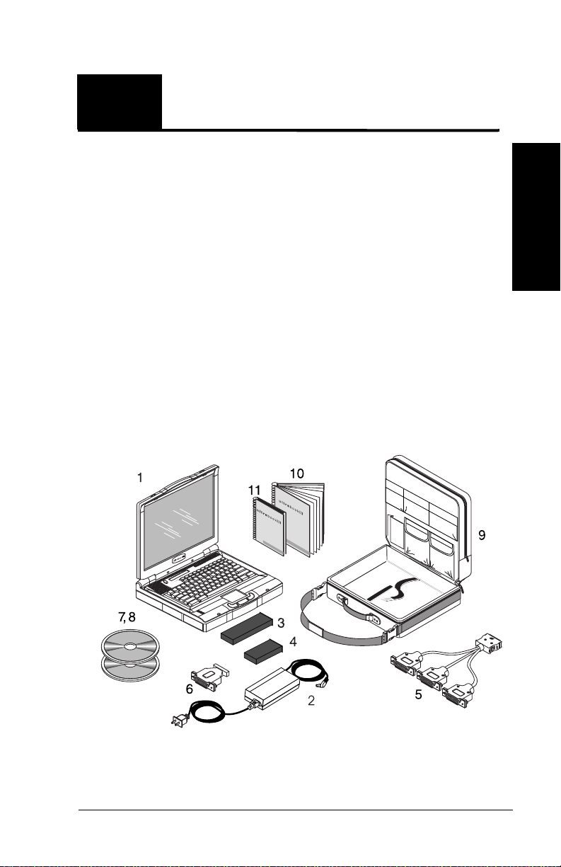
Introducing UltraBookIIi Components
As you unpack your UltraBookIIi, check the shipping
carton and the components inside it for damage. Figure
1-1 shows the items you should find in your shipping
carton.
Introduction
Figure 1-1 UltraBookIIi Components
UltraBookIIi User Guide 1–1
Page 18

If either the shipping carton is damaged or the
UltraBookIIi components are missing or damaged,
please contact your shipper or dealer immediately.
Each carton contains:
1. UltraBookIIi portable workstation
2. AC adapter and power cord
3. Rechargeable battery pack
4. Removable hard drive
5. I/O break-out cable
6. J13W3-to-VGA adapter
7. Solaris 2.x or higher compact disc
8. Tadpole-RDI software compact disc
9. Carrying case
10. UltraBookIIi User Guide (this manual)
11. Solaris Software Installation Guide
Optional UltraBookIIi Accessories:
• Optional external floppy drive (not shown)
• Optional CD-ROM drive (not shown)
• Optional fax/modem PCMCIA card (not
shown)
1–2 UltraBookIIi User Guide
Page 19

Introducing UltraBookIIi Features
Your new UltraBookIIi includes the following features:
• An UltraSPARC-IIi-compatible
motherboard, running at 400 MHz with a
2 MB data and instruction cache
• 256 MB of high-speed RAM, upgradeable to
1 GB
• 14.1 inch display with 1024 x 768 resolution,
supporting a 256K-color palette and 64shades of gray
• A full-size 97-key SUN Type-5 compatible
keyboard with 12 function keys
• An integrated three-button trackpad
• A status LCD that displays system status
icons
• Up to three removable hard disk drives
(HDDs) of varying capacity
Depending on your configuration, you may
have two removable HDDs and one
removable battery.
• Audio input and output jacks that support:
• Stereo headphones, for private listening
• Line Out, for connection to external
stereophonic devices
• Line In, for connection to external
stereo audio sources
Introduction
• Mono/stereo microphone, for
connection to an external microphone
• Internal monophonic speaker
• 2 PCMCIA Type I or Type II cards, or 1
Type III slot
UltraBookIIi User Guide 1–3
Page 20

• A connector for an optional low-profile
external floppy disk drive
• A 68-pin Ultra/Fast-Wide SCSI port
• Two RS-232C serial ports for connecting an
external keyboard or mouse
• A port for connecting an AC power adapter
• A J13W3 port for attaching an optional
external monitor
• A standard RJ45 port that supports both
10-Base T and 100-Base T twisted pair
Ethernet connections
• A single 50-pin port and I/O break-out cable
(supplied) that supports two serial and one
parallel cable for connecting industrystandard TIA/EIA-232-F and Centronics
devices
For more information about the features listed here, see
Appendix A of this guide.
For tips on using the features listed here, see Chapter 3
of this guide.
1–4 UltraBookIIi User Guide
Page 21

Customer Service and Support
If the information presented in this guide does not meet
your needs, or you have questions, you may contact
Tadpole-RDI’s Customer Service and Support staff.
North America
7:00 AM to 6:00 PM PST
Tel: 1-800 734-7030
Fax: (760) 930-0762
E-mail: support@tadpolerdi.com
Europe
9:00 AM to 5:00 PM GMT
Tel: +44 1223 428200
Fax: +44 1223 428201
E-mail: support@tadpolerdi.com
Before you call, have the serial number for your
UltraBookIIi nearby. This number appears on the
bottom of the UltraBook.
If you received an error message, it will also help if you
write down the following information:
1. Serial number of your system.
2. The exact description of the problem.
Introduction
3. The task you were performing when you encountered the problem.
4. The command you typed when the error occurred. You may want to check the command line to make sure you did not make a
mistake.
5. The directory you were in. You can use
“pwd” to obtain this information.
6. The account you were using. You can use
“whoami” to obtain this information.
7. Version of the operating system you are using. You can use “uname -a” or “more /etc/
release” to obtain this information. Refer to
page 6-9 for details about these commands.
UltraBookIIi User Guide 1–5
Page 22

Notes
1–6 UltraBookIIi User Guide
Page 23
2
2
Quick-Start provides a brief, pictorial introduction to get you
started. The next chapter, Using UltraBookIIi, describes more
detailed information about these features. A few minutes spent on
these two chapters will ensure you get the most out of
UltraBookIIi. For more detailed hardware descriptions, see
Appendix A of this manual.
Quick-Start
Quick-Start
By the end of these eight steps, you’ll be ready to start
working with your UltraBookIIi.
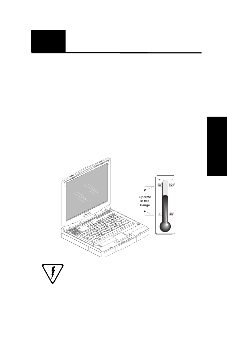
Step 1: Check the ambient air temperature.
Quick-Start
Caution: If your workstation has been
exposed to temperature extremes
(variations of more than 10 degrees of
temperature or 10 percentage points of
humidity), you will need to stabilize the
UltraBookIIi User Guide 2–1
Page 24
workstation’s temperature. Let your
UltraBookIIi adjust to room temperature
before proceeding. As shown in Step 1, the
operating temperature range is 4° to 40° C.
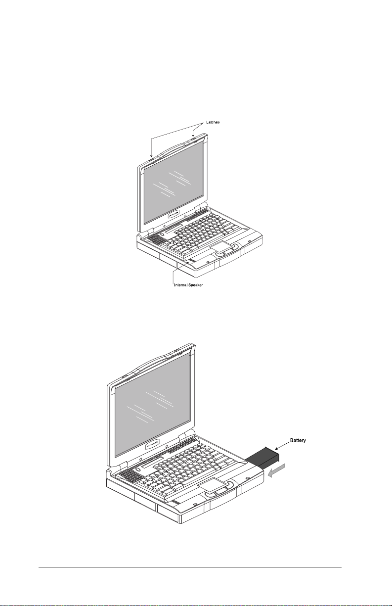
Step 2: Open the UltraBookIIi
Open the UltraBookIIi display screen by sliding the
display cover latches as shown in Step 2.
Step 3: Install the Lithium-Ion battery.
2–2 UltraBookIIi User Guide
Page 25
Insert the battery pack into the bay. Push in until you
hear it click into place. The battery bay is located on
the same side of the unit as the PCMCIA and parallel
and serial ports.
Warning: Never use alkaline batteries
with the UltraBookIIi. Alkaline batteries
cannot be recharged and may explode if you
try to recharge them. Only use the LithiumIon battery supplied with the system.
Warnung: Versuchen sie auf keinen Fall,
Ihre UltraBookIIi workstation mi
Trockenbatterien (Primarzellen) zu
betreiben oder solche mit dem Netz/
Ladegerat zu laden. Versuche dieser Art
konnen Personen-oder Sachsaden zur
Folge Haben.
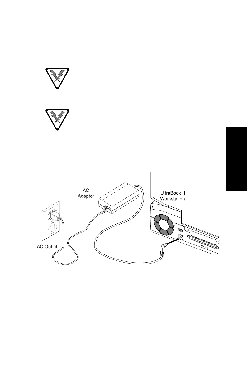
Step 4: Plug in the AC power adapter.
Quick-Start
This shows connecting the AC adapter for AC power
operation. The battery need not be installed for AC
operation. Your AC adapter may look slightly
different than the one pictured here. For more
detailed instructions on plugging in the AC adapter,
see page 3-3.
UltraBookIIi User Guide 2–3
Page 26
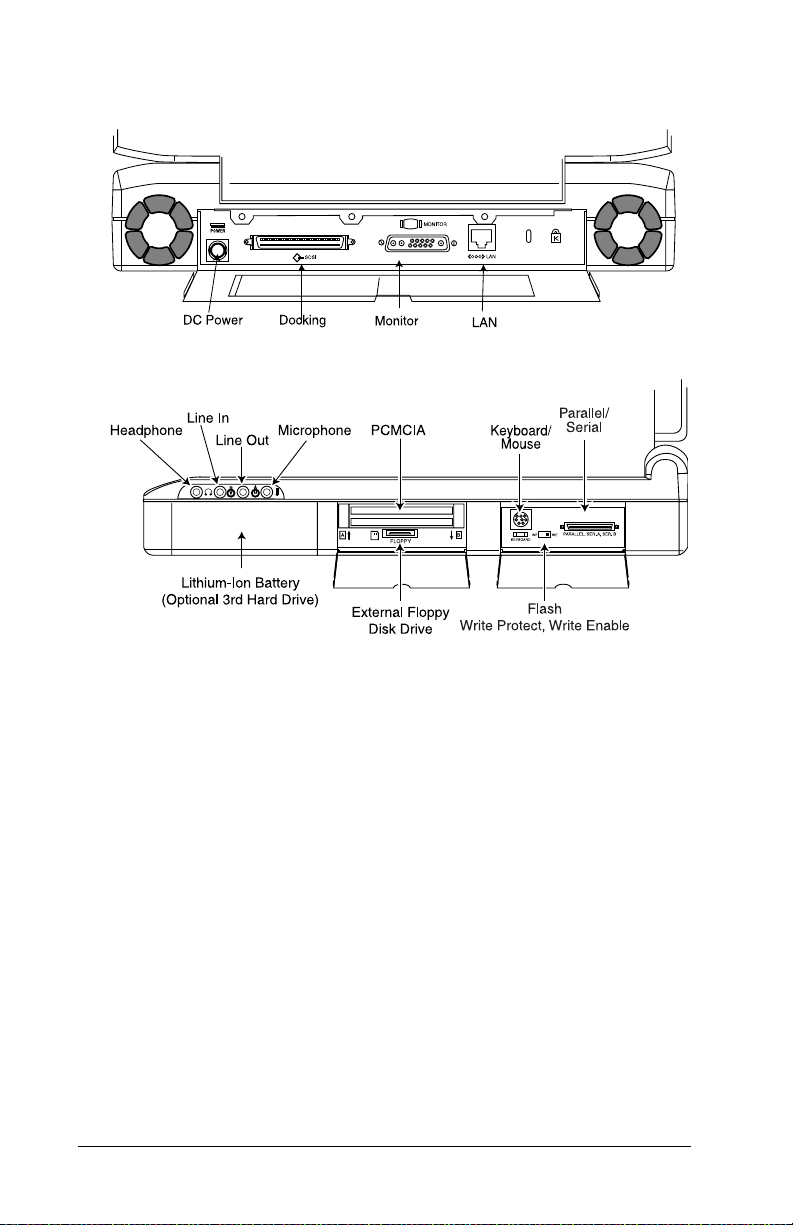
Step 5: Open the UltraBookIIi back and side panels.
Step 5 continued.
Step 5 shows the back panel. Although the UltraBookIIi
is completely self-contained, the back panel provides
access for connecting the workstation to a wide variety
of external devices, including Ethernet networks. Lower
the cover plate and connect the external device to the
appropriate connector. For serial or parallel
connections, use the supplied I/O break-out cable. For
Ultra/Fast-Wide SCSI connections, use the SCSI port
shown in Step 5. See Chapter 2 for more on connections.
Turn on all external devices, then turn on your
UltraBookIIi, as shown in Step 6.
2–4 UltraBookIIi User Guide
Page 27
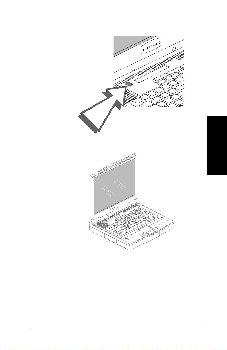
Step 6: Turn the power switch on.
Step 7: View the initial system screens.
Quick-Start
After the self-tests have been successfully completed,
an initial message appears. Then system messages
scroll as the operating system loads.
If the system is booted with the factory software load
intact, the Common Desktop Environment (CDE)
login banner appears. Log on at this time and follow
the prompts.
UltraBookIIi User Guide 2–5
Page 28

Step 8: Log on to the system
If the factory software load is altered, the
CDE may not appear. If this is the case, after
the last system message, the screen displays
the login prompt and you can log into the
system. At this point, you may start your
application.
This concludes Quick-Start. The next chapter, Using
UltraBookIIi, provides more detailed information about
the Quick-Start tasks.
2–6 UltraBookIIi User Guide
Page 29

3
3
This chapter provides more detailed information about the QuickStart tasks described in Chapter 2. A few minutes spent here will
ensure you get the most out of UltraBookIIi.
Using UltraBookIIi
Setting Up
The UltraBookIIi is designed to provide many years of
error-free operation. The workstation will last longer
by following these guidelines:
• Position the UltraBookIIi so you can
easily access the connectors on the back
and side panels.
• The area should be free of obstructions,
allowing you to open the display screen
completely, without hindrance.
• Adequate ventilation is required for the
UltraBookIIi. Do not cover or block the
ventilation slots or fans on the case.
Never spray or directly apply strong
cleaners or solvents to the UltraBookIIi
case or LCD.
Using
Opening the Display Cover
The display is located on the inside of the top cover.
When you are not using the UltraBookIIi, the cover
should remain closed. This protects the display
against damage.
UltraBookIIi User Guide 3–1
Page 30
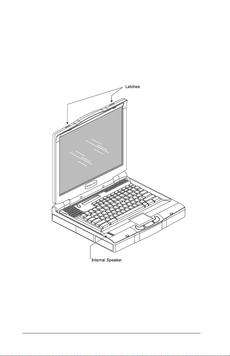
To open the display cover:
1. Slide the two display cover latches outward
to the left and right sides of the unit (see
Figure 3-1).
2. Gently raise the cover to its full, upright position.
Figure 3-1 Raising the Display Cover
You can adjust the screen up to 27 degrees from vertical
for a better viewing angle. Use the backlight intensity
keys on the integral keyboard to adjust the brightness of
the backlight to achieve the best viewing conditions.
3–2 UltraBookIIi User Guide
Page 31

To close the display cover:
1. Gently pull the cover forward and down.
2. Carefully press the back of the cover down
toward the keyboard until both case
latches “click” into their closed positions.
At this point, you can connect the UltraBookIIi to your
selected optional equipment and power up the
workstation.
Providing Power
The UltraBookIIi can operate from an AC power
adapter or a rechargeable Lithium-Ion battery pack.
Using an AC adapter
You may use AC power to operate the UltraBookIIi.
The battery need not be installed for AC operation.
To power the UltraBookIIi from AC power:
1. Locate the UltraBookIIi near a grounded
AC outlet.
2. Make sure the outlet is not controlled by a
wall switch, which can cause the workstation to be turned off accidentally.
Warning: Use only the supplied AC
adapter with the UltraBookIIi. Do not use
an AC adapter designed for use with
another product.
Using
UltraBookIIi User Guide 3–3
Page 32

3. Plug the connector from the AC adapter
into the power input socket on the UltraBookIIi. Then plug the AC cable plug into a
nearby AC outlet.
Figure 3-2 Connecting to AC Power
The AC adapter can be plugged into a
100 – 240-Volt source at 50 – 60 Hz. The AC
adapter will automatically adjust to the AC
input voltage and frequency. The only
requirement is that the AC adapter/charger
must correctly fit the AC outlet.
To unplug the AC Adapter: Unplug the AC cable
from the AC outlet. Then slide the connector from
the AC adapter out of the power input socket on the
UltraBookIIi.
After installing a new battery pack, use the AC adapter
to recharge the battery pack. It takes about 3 hours to
recharge a new battery when the UltraBookIIi is turned
off. After fully charging the battery pack, you can
operate the UltraBookIIi for about 1 hour, depending on
your configuration and application.
3–4 UltraBookIIi User Guide
Page 33

Using Batteries
UltraBookIIi includes three device bays,
which may be occupied by one of several
devices. If the device bay on the right side of
the unit (the same side as the PCMCIA and
parallel and serial ports) is occupied by a
hard disk drive, you will not be able to run
UltraBookIIi on battery power.
To install the battery pack:
The battery can be installed with the
UltraBookIIi powered on or off.
Insert the battery pack in the bay. Push in until you
hear it click into place. The battery bay is located in
the same side of the unit as the PCMCIA and parallel
and serial ports.
Figure 3-3 Installing the Battery Pack
To remove the battery pack:
1. Shut down the UltraBookIIi according to
the instructions on page 3-10.
2. Turn the UltraBookIIi over.
UltraBookIIi User Guide 3–5
Using
Page 34

3. Press the battery latch (see Figure 3-4)
away from the battery.
Figure 3-4 Removing the Battery Pack
4. Grasp the battery’s faceplate and gently
pull it out of the battery bay.
Figure 3-5 Removing the Battery Pack (cont’d)
3–6 UltraBookIIi User Guide
Page 35

Operating UltraBookIIi
Before turning on your UltraBookIIi workstation and
beginning your day, you will need to prepare the
workstation. This includes acclimating the
workstation to its environment and starting its
operating system.
Starting UltraBookIIi
To ensure long life and ease of operation, you need to
follow a few general guidelines when starting up and
shutting down your UltraBookIIi workstation.
Caution: Failure to start up and shut
down the UltraBookIIi workstation
properly can damage important system files
and may affect your product warranty.
To start the UltraBookIIi:
1. Make sure the UltraBookIIi is at room
temperature before powering up. This is
particularly important when the workstation is brought from a very cold environment into a warm room. In such cases,
moisture can condense on and inside the
workstation and cause problems. Allow at
least two hours for the UltraBookIIi’s
temperature to stabilize after bringing it
from a very cold or very warm environment before proceeding.
Using
2. (Optional) If you will be using the UltraBookIIi on an Ethernet network, you will
need to:
a. Contact the person responsible for your com-
puter network (the Network Administrator)
to obtain the following applicable information:
• A host name that does not
duplicate an existing host name
• An IP address
UltraBookIIi User Guide 3–7
Page 36

• An optional Network Information
Service (NIS) domain name
• A user account and password if
using NIS
•An Ethernet cable
• A connection to the desired
Ethernet network
b. Connect the Ethernet cable to the 10-Base T/
100-Base T Ethernet connector.
3. Make sure that all cables attached to peripherals (such as printers, mouse, monitor,
or SCSI devices) are securely plugged into
the correct connectors. Pay particular attention to the two serial ports: check that
th e d ev ic e i nt en ded fo r a tt achm en t t o po rt A
is not accidentally plugged into port B.
4. Make certain that each device is plugged
into an AC outlet or power strip.
5. If you are using SCSI devices, please refer to
Using the Ultra/Fast-Wide SCSI Port later
in this chapter for more information. You
may also need to consult your SCSI device
documentation.
6. Use the UltraBookIIi’s power switch to turn
on your workstation.
The UltraBookIIi begins its self-test diagnostics and
starts to boot. It is normal for the screen to be blank for
up to 20 seconds before displaying the following initial
message:
UltraBookIIi
ROM Rev.x.xx, Serial #xxxxxxx
xx MB memory installed, Keyboard Present
Ethernet address x:x:xx:x:x:xx, Host ID: xxxxxxxx
3–8 UltraBookIIi User Guide
Page 37

A variety of system messages will be displayed on the
screen as Solaris continues to boot. After the last
system message, the screen will display the
“hostname console login” prompt.
hostname console login:
If the UltraBookIIi does not respond when the power
switch is turned on, refer to Chapter 4 of this guide for
troubleshooting suggestions.
After powering-up the UltraBookIIi for the
first time, you are ready to configure your
workstation. Consult your system
administrator for details.
Restarting UltraBookIIi
Restarting an UltraBookIIi that has been halted and
powered down is a simple procedure.
To restart the UltraBookIIi:
1. Verify that cables from all connected peripheral devices, such as SCSI devices or
an external monitor, are connected to the
appropriate connectors on the back of the
UltraBookIIi.
Using
2. Power-up the peripherals before powering-up the UltraBookIIi (see the peripheral manuals for more information).
3. Turn on the UltraBookIIi.
The UltraBookIIi begins its self-test diagnostics
and starts to boot. It is normal for the screen to be
blank for up to 20 seconds before displaying the
following initial message:
UltraBookIIi
ROM Rev.x.xx, Serial #xxxxxxx
xx MB memory installed, Keyboard Present
Ethernet address x:x:xx:x:x:xx, Host ID: xxxxxxxx
UltraBookIIi User Guide 3–9
Page 38

Various system messages will appear on the screen
during the boot process. After the last system message,
the screen will display the “host name console login”
prompt, where “host name” is the one you entered when
you configured the UltraBookIIi:
hostname console login:
4. Enter your user ID at the “hostname console login” prompt and press Enter.
The following prompt appears:
Password:
5. Enter your password at the “Password”
prompt and press Enter.
Shutting UltraBookIIi Down
Before turning off your UltraBookIIi for the day, save
your work, close all programs and databases, and shut
down its operating system. You may also want to power
down any peripheral devices you have connected to the
UltraBookIIi.
Using RDIuts
If you have RDIuts installed on your UltraBookIIi, this
power management software will automatically close
your programs and databases and shut down the
operating system safely.
RDIuts is installed with the other system software at
the factory, but if you have reloaded Solaris or
repartitioned the hard disk drive, you will need to reload
RDIuts or manually shut down your programs and
operating system each time you are finished for the day.
Caution: If you are not certain RDIuts is
installed on your workstation, DO NOT
simply turn off the power to your workstation
as this can damage or destroy critical
operating system files and data. Failing to
3–10 UltraBookIIi User Guide
Page 39

properly shut down the operating system
and workstation can also damage attached
peripheral devices as well as the
workstation itself.
To check if RDIuts is installed:
1. At the “#” prompt, type
pkginfo | grep RDIuts.
2. If RDIuts is present, this command will
return the following information:
system RDIuts Tadpole-RDI UltraBook-IIi Utilities for Solaris 7
3. If RDIuts is not present, the “#” prompt
will return with no response. Contact
your system administrator if you need assistance reloading RDIuts from the VWA
Install CD-ROM or downloading it via
FTP from www.tadpolerdi.com.
To shut down the UltraBookIIi safely if RDIuts
is NOT installed:
1. Save your work and close any application
or database that may have work in
progress.
Using
2. At the “#” prompt, type init 0 to shut
down the operating system.
3. Press the power switch.
4. Power down peripherals as needed.
To shut down the UltraBookIIi with RDIuts
installed (normal shutdown):
1. Save your work.
2. Press the power switch.
3. Power down peripherals as needed.
UltraBookIIi User Guide 3–11
Page 40

Moving UltraBookIIi
1. If you want to move the UltraBookIIi after
shutting down, disconnect all cables and
connectors (including the AC adapter cable)
from the UltraBookIIi.
2. Close and latch the rear panel cover, then
fold the display cover down and close and
latch the case.
3. You can now move the UltraBookIIi to a
new location, reconnect, and restart.
3–12 UltraBookIIi User Guide
Page 41

Using UltraBookIIi Features
This section contains operational tips and other
information unique to the UltraBookIIi feature set. For
more detailed information on a listed feature, refer to
Appendix B, “UltraBookIIi Specifications”.
Removing Hard Disk Drives
The UltraBookIIi comes equipped with up to three
removable hard disk drives.
To remove a hard disk drive:
1. Shut down the UltraBookIIi according to
the instructions on page 3-10.
2. Turn the UltraBookIIi over.
3. Press the hard disk drive latch (see Figure
3-6) away from the drive.
Figure 3-6 Removing the Hard Disk Drive
UltraBookIIi User Guide 3–13
Using
Page 42

4. Grasp the drive’s faceplate and gently pull it
out of the drive bay.
Figure 3-7 Removing the Hard Disk Drive (cont’d)
3–14 UltraBookIIi User Guide
Page 43

To insert a hard disk drive:
1. Shut down the UltraBookIIi according to
the instructions on page 3-10.
2. Insert the drive into the drive bay.
Figure 3-8 Installing a Hard Disk Drive
3. Press gently until you hear the drive click
into place.
Recording with the External Microphone
To use this microphone to record:
1. Make sure the recording source is sufficiently close to the microphone (1 to 2 ft).
2. Unplug any external audio input devices
connected to the UltraBookIIi.
Ejecting PCMCIA Cards
The eject buttons work each slot independently. To
eject a card, push the applicable PCMCIA eject button.
The card will release and slide out.
UltraBookIIi User Guide 3–15
Using
Page 44

Using an External Keyboard or Pointing Device
• When the UltraBookIIi is on and an
external keyboard is connected, the system
returns to OBP. Typing go and pressing
Enter returns you to the Sun operating
system.
• An external keyboard and the on-board
keyboard can both be used for typing, along
with a single pointing device (mouse or
trackpad).
• The integrated trackpad is disabled
whenever an external pointing device is
used.
3–16 UltraBookIIi User Guide
Page 45

Using an External Display
To connect an external monitor:
1. Shut down the UltraBookIIi according to
the instructions on page 3-10.
2. To connect a Sun-type external monitor,
connect it directly to the UltraBookIIi’s
external video port. Refer to Appendix E,
External Monitor Matrix, for more
information.
3. For other monitors, attach a
J13W3-to-VGA adapter to the UltraBookIIi’s external video port. Then connect the external monitor to the other end
of the adapter. Refer to Appendix E, External Monitor Matrix, for more information.
Figure 3-9 UltraBookIIi Rear Access port
Connecting an Ethernet Cable
To connect the UltraBookIIi to an Ethernet
network:
1. Shut down the UltraBookIIi according to
the instructions on page 3-10.
2. Set it on a work surface near the Ethernet
twisted-pair cable or transceiver/MAU.
UltraBookIIi User Guide 3–17
Using
Page 46

3. Attach a twisted-pair cable to the UltraBookIIi’s 10-Base T/100-Base T Ethernet
connector (see Figure 3-9).
Using the Serial/Parallel Port
The UltraBookIIi back panel has a 50-pin connector
housing two serial ports and a parallel port (see Figure
3-10).
To access serial and parallel ports:
1. Shut down the UltraBookIIi according to
the instructions on page 3-10.
2. Turn off the serial devices you will be connecting to it.
3. Connect the male end of the I/O break-out
cable to the UltraBookIIi’s 50-pin connector
on the side panel.
4. The other end of the I/O break-out cable has
two 25-pin connectors for attaching serial
devices and a parallel connector for attaching parallel devices (see Figure 3-10). Make
the appropriate serial and parallel connections.
Figure 3-10 Serial and Parallel Connections
3–18 UltraBookIIi User Guide
Page 47

For a list of pin assignments for the UltraBookIIi
connector and I/O break-out cable, refer to
Appendix C.
The two serial ports are designated A and B on the
I/O break-out cable. When you connect serial devices
to the I/O break-out cable, make sure the device
intended for port A is plugged into the port A
connector and the device for port B is plugged into the
port B connector.
Using the Ultra/Fast-Wide SCSI Port
The UltraBookIIi back panel has an Ultra/Fast-Wide
SCSI port (see Figure 3-11). For more detailed
technical information on the SCSI port, refer to
Appendix A, Hardware, page A-19.
To access the SCSI port:
1. Shut down the UltraBookIIi according to
the instructions on page 3-10.
2. Turn off the SCSI device(s) you will be
connecting to it.
3. Connect the male end of the SCSI cable to
the UltraBookIIi’s SCSI connector on the
rear panel.
Using
Figure 3-11 UltraBookIIi Rear Access port
UltraBookIIi User Guide 3–19
Page 48

4. Make the appropriate connection to your
SCSI device(s), daisy-chaining and terminating as required. See Terminating Devices Attached to the SCSI Port later in this
section.
For a list of pin assignments for the UltraBookIIi Ultra/
Fast-Wide SCSI port, refer to Appendix C.
Terminating Devices Attached to the SCSI Port
Due to termination requirements and bus loading,
follow the configuration guidelines discussed in this
section and in your SCSI device documentation.
Daisy-chained SCSI devices—Termination must
occur after the last SCSI device. Check the SCSI device
manual to see if the device is to be powered on before the
restarting of the UltraBookIIi.
External SCSI devices—Use an active terminator
with the appropriate connector.
SCSI Bus—External devices can have a maximum
SCSI bus length of 2 meters and must have active
termination installed at the last device on the external
bus.
If SCSI devices are connected to the UltraBookIIi,
install an active SCSI bus terminator on the last SCSI
device only; otherwise you may experience erratic
performance/ operation. The UltraBookIIi provides
5 VDC termpwr for SCSI terminators.
Caution: External devices can have a
maximum SCSI bus length of 2 meters and
must have active termination installed at the
last device on the external bus.
Starting Order
Turn on peripherals such as SCSI devices or a monitor
before starting the UltraBookIIi. Refer to the
instructions that came with the peripherals for more
information about starting order.
3–20 UltraBookIIi User Guide
Page 49

Any SCSI devices not turned on when you
start the UltraBookIIi will not be
recognized. If this occurs, shut down the
UltraBookIIi according to the instructions
on page 3-10, then turn on the SCS I devices
and start the UltraBookIIi again.
Upgrading Memory (RAM)
UltraBookIIi can support up to 1 GB of random access
memory (RAM). To upgrade RAM, add or replace
RAM modules, available from Tadpole-RDI or
authorized dealers in 128 MB, 256 MB, and 512 MB
sizes.
Warning: Be sure to wear a grounding
strap when upgrading memory. If you do
not, you may damage the UltraBookIIi and
risk voiding your warranty.
To add a new memory module:
1. Shut down the UltraBookIIi according to
the instructions on page 3-10.
2. Unplug the AC adapter/charger and remove the battery pack from the system.
3. Turn the UltraBookIIi over.
UltraBookIIi User Guide 3–21
Using
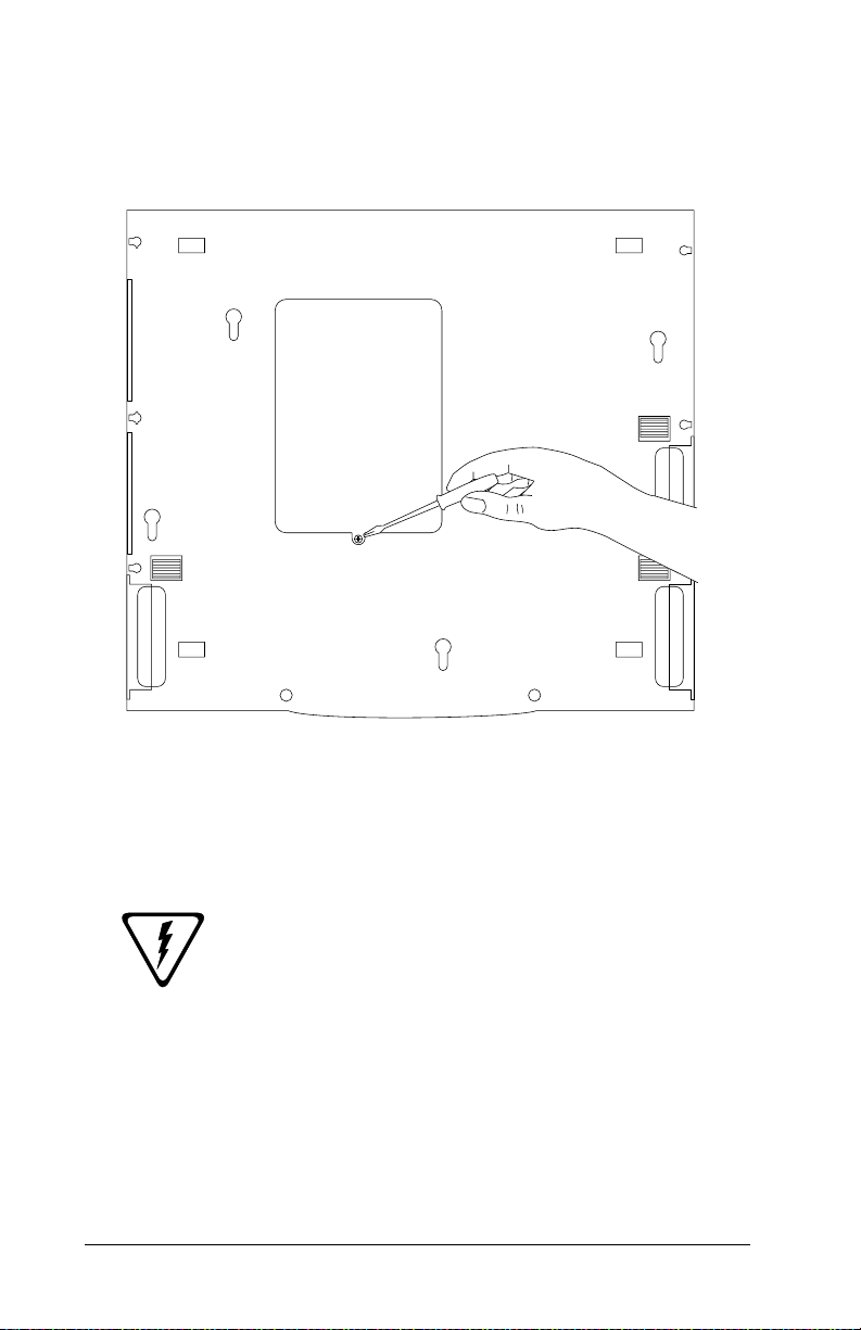
Page 50

4. Using a small Phillips screwdriver, remove
the memory access cover as shown in Figure
3-9.
Figure 3-9 Removing the Memory Cover
5. Using a Phillips screwdriver, remove existing mounting screws before inserting memory board.
6. Insert the new module in the available slot
(as shown in Figure 3-10) pressing gently
but firmly until it is fully seated in the connector.
3–22 UltraBookIIi User Guide
Page 51

7. Using a small Phillips screwdriver, insert
and tighten the mounting screws that
came with the system.
Figure 3-10 Installing the Memory Module
8. Replace the memory access cover and
tighten screw.
To replace or upgrade existing memory
modules:
1. Shut down the UltraBookIIi according to
the instructions on page 3-10.
2. Unplug the AC adapter/charger and remove the battery pack from the system.
3. Turn the UltraBookIIi over.
UltraBookIIi User Guide 3–23
Using
Page 52
4. Using a small Phillips screwdriver, remove
the memory access cover as shown below.
Figure 3-11 Removing the Memory Cover
5. Remove the memory module(s) using one of
the procedures described on the following
pages.
Caution: Do not place the screwdriver
against any printed circuits, individual
memory module chips, or points of contact
other than those shown in the following
illustrations. Prying at other points of contact
may damage your memory modules or the
main system board and void your warranty
with Tadpole-RDI.
a. Using a small Phillips screwdriver, remove the
mounting screws on the memory module(s) you
are replacing.
3–24 UltraBookIIi User Guide
Page 53

b. Using a small flat-tip screwdriver, pry gently
upward against the outer edges of the
system’s memory module, as shown in Figure
3-12.
Figure 3-12 Removing the Secondary Memory Module
c. Grasping the memory module by its outer
edges, carefully lift the memory module away
from its RAM connector and the unit.
Caution: Pry gently upward at the
leverage points shown in Figure 3-12 and
Figure 3-13 or you may damage your
memory modules or the main system board
and void your system warranty. The
leverage points are numbered and you must
pry gently upward in the order shown to
remove the memory modules without
damaging them.
UltraBookIIi User Guide 3–25
Using
Page 54

d. (Optional) Using a small flat-tip screwdriver,
pry gently upward against the outer edges of the
system’s memory module until the memory
module is free of its RAM connector, as shown in
Figure 3-13.
Figure 3-13 Removing the Main Memory Module
e. Grasping the memory module by its outer edges,
carefully lift the memory module away from its
RAM connector and the unit.
f. Replace the memory module(s) as described on
page 3-21.
g. Install the memory mounting screws.
3–26 UltraBookIIi User Guide
Page 55

If you have only one memory module installed,
use this procedure to remove it.
If you are installing or upgrading only one
main memory module, install it in the
position of the memory module shown in
Figure 3-14 (the memory slot closest to the
rear of the unit).
a. Using a small flat-tip screw driver, pry gently
upward against the outer edges of the
system’s memory module until the memory
module is free of its RAM connector, as shown
in Figure 3-14.
Figure 3-14 Removing the Main Memory Module
Caution: Pry gently upward at the
leverage points shown in Figure 3-14 or you
may damage your memory modules or the
main system board and void your system
UltraBookIIi User Guide 3–27
Using
Page 56

warranty. The leverage points are numbered
and you must pry gently upward in the order
shown to remove the memory modules
without damaging them.
b. Grasping the memory module by its outer edges,
carefully lift the memory module away from its
memory connector and the unit.
c. Replace the memory module as described on
page 3-21.
3–28 UltraBookIIi User Guide
Page 57

4
4
It is important to maintain the UltraBookIIi. This chapter provides
information for cleaning, packing, and storing the workstation, and
battery maintenance.
Maintaining UltraBookIIi
Warning: Any service and upgrades to the
UltraBookIIi which require opening and
removing the unit’s case must be performed by
a trained technician only. Otherwise, you may
encounter personal injury, damage the
UltraBookIIi, and void your warranty.
WARNUNG: Das Öffnen des Gehäuses zum
Zwecke der Reparatur oder zum Wechseln/
Hinzufügen von Modulen darf nur von einem
qualifizierten Servicetechniker durchgeführt
werden. Es besteht Gefahr durch
Elektroschock. Durch unsachgemässe
Behandlung kann ihre UltraBookIIi
Workstation beschädigt werden, ausserdem
erlischt dadurch die Garantie.
Caution: Changes or modifications to the
UltraBookIIi not expressly approved by
Tadpole-RDI could void your authority to
operate UltraBookIIi.
If the product does not operate normally, adjust only
those controls that are covered by the operating
instructions. Unplug the UltraBookIIi from the power
outlet and call Customer Service under any of the
following conditions:
• If the power cord or plug is damaged or
frayed.
• If liquid has been spilled into the
workstation or it has been exposed to rain or
water.
UltraBookIIi User Guide 4–1
Maintenance
Page 58

• If the workstation has been dropped or the
case has been damaged.
• If the workstation exhibits a distinct
change in performance for the worse.
• If the display is cracked.
Stop! After your warranty period, if you ever
have to remove the main system unit cover,
observe the following precautions:
The power supply cord must be unplugged
and the battery pack removed from the system
before the main system unit cover is removed.
(Separe le cordon d'alimentation et puls enleve
le couverde.)
Once removed, the cover must be replaced and
screwed in position before the power supply is
plugged back in. (Apres le couverde a encleve,
visse le couverde en place et remettre le cordon
d'alimentation.)
Cleaning The UltraBookIIi
As a portable workstation, the UltraBookIIi may collect
dust and dirt, requiring occasional cleaning.
To clean the UltraBookIIi:
1. Shut down the UltraBookIIi according to
the instructions on page 3-10.
2. Unplug the AC adapter/charger and remove
the battery pack from the system before
cleaning.
3. Once the UltraBookIIi is turned off, you
may clean the cases and key tops with a soft
cloth dampened only with mild soap and water.
4–2 UltraBookIIi User Guide
Page 59

Caution: Never use any water or waterbased products on the display panel. Use only
a dry, soft cloth. Screen damage could result.
4. Avoid getting any liquid directly on the
UltraBookIIi. Moisten a lint-free cloth with
cleaner and use the damp cloth to clean the
case.
5. Use cotton-tipped swabs, moistened with
cleaner, to clean key tops, slots, and recesses. Do not use liquid cleaner on connectors or metal contacts. Use only a
commercial contact cleaning spray on such
parts.
Caution: Never use flammable or organic
cle an in g so lv en ts or ab ra si ve c le an er s t o c le an
the UltraBookIIi. Such cleaners will damage
the case's finish.
6. Use a commercial floppy disk drive cleaning
kit to clean the floppy disk drive. Follow the
kit manufacturer's instructions carefully.
7. Do not use liquid cleaners on the interior of
the UltraBookIIi. Accumulated dust may be
blown out of the interior using dry, lowpressure compressed air. Always wear eye
protection when using compressed air to
blow out dust.
Packing and Shipping
To pack the UltraBookIIi for shipment:
1. Disconnect all cables from connectors on the
UltraBookIIi rear panel. Do not pack the
UltraBookIIi with cables still attached to
connectors.
2. Verify the connector panel on the back of
the UltraBookIIi and the battery compartment are closed.
UltraBookIIi User Guide 4–3
Maintenance
Page 60

Storage
3. Close and lock the display cover.
4. Pack the UltraBookIIi in the original shipping container. Follow the instructions
printed on the container for proper packing
order and configuration.
Caution: Damage caused by shipping the
UltraBookIIi workstation in containers other
than the original shipping container is
NOT COVERED BY THE WARRANTY.
KEEP AND USE THE ORIGINAL
SHIPPING CONTAINER.
If the original materials are unavailable,
contact Tadpole-RDI customer service for a
new container. The original shipping
containers are specifically designed for the
UltraBookIIi workstation.
5. Ship with any commercial carrier.
If you intend to store the UltraBookIIi longer
than 60 days:
1. Make a complete backup copy of the contents of the hard disk(s).
2. Fully discharge and remove the battery
pack (see Battery Pack Maintenance). Do
not store the UltraBookIIi for extended periods with the battery pack installed.
3. Disconnect all cables and pack the UltraBookIIi as described in Packing and Shipping earlier in this guide.
4–4 UltraBookIIi User Guide
Page 61

When you want to start using the UltraBookIIi
again:
1. Give the UltraBookIIi enough time to stabilize at room temperature before operating.
This is particularly important when the
workstation is brought from a very cold environment into a warm room. In such cases,
moisture can condense on and inside the
workstation and can cause problems. Allow
at least two hours for the workstation temperature to stabilize after bringing it from a
very cold or very warm environment before
proceeding.
2. Reinstall the battery pack and charge it for
three hours without operating the UltraBookIIi before attempting to operate the
UltraBookIIi on battery power.
Low Battery Shutdown
The UltraBookIIi's battery is uniquely designed to
provide the longest possible duration. As with any
battery, however, prolonged use will require the battery
to be recharged. Typically, battery power lasts up to
1 hour, depending on the type and number of processes
you are performing.
To prolong battery use, use the brightness push-buttons
(FN Bri+/Bri-) on the integral keyboard to reduce the
brightness of, and the power consumption by, the LCD.
As battery power decreases, the UltraBookIIi performs
a sequence of events, described in the table on the next
page. During this sequence, the UltraBookIIi provides
constant messages and an audible alarm informing you
of the battery's current status. If you have CDE or
OpenWindows running, PowerTool also appears, which
displays the current battery voltage. See the note
regarding user privileges on page 5-3. If you desire, you
can use the PowerTool to turn off the alarm.
UltraBookIIi User Guide 4–5
Maintenance
Page 62

The Duration column in the table on the next
page reflects approximate times during
typical operating activities and conditions.
Battery
Status
Fully
charged
Low
battery
condition
Critical
battery
condition
Power
Shutdown
Duration
(Estimated)
System
Actions
Actions You Can
Perform
Up to 1 hour None None required
10 - 15 Warning mes-
sage displayed
on the Con-
Attach AC adapter, or
save and begin exiting
processes.
sole.
To complete jobs curAudible warning sounds.
rently running, use
dimmer switch to lower
the LCD intensity and
If OpenWin-
save battery power.
dows is running,
PowerTool
window pops
Use the PowerTool to
turn off the alarm, if
desired.
up, displaying
battery capacity.
2 minutes Power man-
agement daemon starts
system shutdown
sequence, after
Solaris shutdown can-
not be interrupted.
Attaching AC adapter
will still require you to
boot the UltraBookIIi
after the shutdown.
which it enters
PROM Monitor (OBP).
1-2 minutes System
remains in
OBP until bat-
Connect the AC adapter
and reboot the Ultra-
BookIIi.
tery power is
exhausted,
causing automatic power
shutdown.
4–6 UltraBookIIi User Guide
Page 63

Battery Pack Maintenance
When operating the UltraBookIIi from battery power,
pay particular attention to:
1. Low battery warning —When the battery
reaches the end of its charge, a “battery
low” message appears, a beeping alarm
sounds, and a PowerTool window appears if
CDE or OpenWindows is running. These indications mean you have approximately
15 minutes to complete your work before
the battery charge is exhausted.
2. When this occurs, follow the proper procedure to shut down the UltraBookIIi quickly
and safely, or connect the AC adapter to
maintain system operation. The UltraBookIIi will continue to remind you about
the low battery status if you continue to use
battery power.
Refer to Chapter 3, Shutting UltraBookIIi Down, for
more information on shutting down the UltraBookIIi.
• Swapping battery packs—One way to
obtain maximum use out of the
UltraBookIIi's portability is to pre-charge
one or more rechargeable battery packs
before operating the workstation from
battery power. For example, you may
purchase additional battery packs, charge
them, and carry them with you into the
field. As each battery pack becomes
discharged, bring the UltraBookIIi to a halt,
then remove the discharged pack and
replace it with one that is fully charged.
If you shut down the UltraBookIIi to swap
batteries, you must follow proper shutdown
procedures; otherwise, important system files
may be corrupted.
UltraBookIIi User Guide 4–7
Maintenance
Page 64

• Replacing battery packs—When lithium-ion
batteries reach the end of their service life,
they indicate their impending failure by
providing shorter and shorter intervals of
service between recharging and finally by
failing to hold a charge. When this occurs,
you must replace the worn out battery pack
with a new one. Replacement battery packs
can be obtained from an UltraBookIIi
representative.
Caution: Worn battery packs should be
discarded in accordance with the disposal
requirements for your area.
4–8 UltraBookIIi User Guide
Page 65

5
5
Power Management
Understanding the PowerTool
The UltraBookIIi PowerTool allows you to control the
power management behavior of your system. The main
program dialog provides an overview of critical power
management areas, including available battery
capacity, estimated battery time remaining, current
processor speed, and LCD status.
UltraBookIIi User Guide 5–1
Power
Page 66

Figure 5-1 shows the main PowerTool dialog.
Figure 5-1 PowerTool GUI
The PowerTool is installed as /usr/openwin/bin/
powertool when you install the power management
utility.
By default, the PowerTool is configured to pop up
automatically when the low battery condition
configured in /etc/pm/pm.cf is reached. However, you
can run the PowerTool at any time using:
• RDI Icon Application Pop Up Menu
• CDE by executing the command /usr/
openwin/bin/powertool
•OpenWindows
5–2 UltraBookIIi User Guide
Page 67

Non-privileged users need to execute the
command xhost + after OpenWindows has
started for the PowerTool to pop up
automatically during low battery conditions.
This command grants other utilities (such as
the PowerTool) access to the screen. Refer to
the xhost(1) man page for more information.
Caution: If power to the UltraBookIIi is
suddenly turned off and there is no available
battery power, the unit’s power management
features will not be able to perform a graceful
shutdown, which may damage important
system files. For more information on
shutting UltraBookIIi down, see page 3-10.
PowerTool Fields
The main PowerTool dialog, shown in Figure 5-1,
provides access to all PowerTool power management
features. The system displays this dialog if you invoke
the PowerTool under OpenWindows or if the system
reaches a low-power condition.
This dialog includes the following power management
features:
• Fuel Gauge
• Status
• Time Remaining
•CPU Speed
•LCD Off
Fuel Gauge
Capacity shows remaining battery power available to
the system. Capacity displays in cumulative increments
of 100%. This field is for reference only.
Status
Status displays the current status of the system, AC
Power, Battery, Calibration, or Failure. This field
is for reference only.
UltraBookIIi User Guide 5–3
Power
Page 68

Time Remaining
Time Remaining displays the estimated battery time
available to the system. The system estimates time
remaining in minutes. This field is for reference only.
If the system is on AC and a battery is
present, then the time remaining is an
estimation of how much time the system
would have if it switched to battery at the
current capacity. This estimation is based on
the last time the system was used with the
battery.
CPU Speed
CPU Speed displays the current processor speed.
LCD Off
Pressing LCD Off blanks (turns off) the main LCD
display panel and locks the keyboard. Press this button
to reduce power consumption by turning off the main
LCD display panel during critical computations. This
feature also prevents you from inadvertently
interrupting a lengthy process by blocking unwanted
keyboard input. Press one of the buttons of your
pointing device to turn the LCD display panel back on.
The LCD display panel will not power up
again until user input is detected from one of
the buttons of your pointing device. Normal
keyboard input and mouse movement will not
power up the display panel. This functionality
is designed to conserve critical computational
resources where screen display is not
immediately required and prevent
interruptions to critical computations.
Exit
Pressing Exit allows you to quit or halt the PowerTool
dialog.
5–4 UltraBookIIi User Guide
Page 69

After installing a new battery pack, use the AC adapter
to recharge the battery pack. It takes about 3 hours to
recharge a new battery when the UltraBookIIi is turned
off. After fully charging the battery pack, you can
operate the UltraBookIIi for about 1 hour with a single
battery, depending on your configuration and
applications.
PowerTool Menus
The PowerTool menus provide access to additional
power management features.
• Battery
•System
• Profile
Battery
The Battery menu provides access to the battery
management, battery priority, and calibration features.
Battery Management
The Battery Management dialog indicates if the battery
is installed, including capacity, state and availability to
the system. Battery capacity is shown in bargraph and
numerical form by the indicator displayed.
If a battery is not being discharged or charged, the
battery state is shown as Idle, unless a battery requires
calibration. If a battery requires calibration, the word
Calibrate is displayed beneath the battery indicator.
Batteries requiring calibration should be
recalibrated at your earliest opportunity.
Battery calibration requires connection to AC
power. Refer to page 5-8 for instructions.
The Battery Management dialog also allows you to
immediately query the system to update existing
battery management information by pressing
Reprobe. The PowerTool continually monitors and
queries the workstation for the most up to date battery
information.
UltraBookIIi User Guide 5–5
Power
Page 70

You can reach this dialog by opening the main Battery
pull-down menu and selecting Battery Management
from the PowerTool dialog.
Figure 5-2 shows the Battery Management dialog.
Figure 5-2 Battery Management
5–6 UltraBookIIi User Guide
Page 71

Battery Priority
The Battery Priority dialog allows you to establish a
first choice priority of use for the battery modules
installed in your system. Making a selection here directs
the system to use a specific battery module before all
others when running on battery power. You can reach
this dialog by opening the main Battery menu and
selecting Battery Priority from the PowerTool dialog.
Figure 5-3 shows the Battery Priority dialog.
Figure 5-3 Battery Priority
UltraBookIIi User Guide 5–7
Power
Page 72

Calibration
The Calibration dialog allows you to calibrate a specific
battery for use with the Power Tool Fuel Gauge shown
in Figure 5-1. You can calibrate the main system battery
by pressing Calibrate at the Calibration dialog. You
can reach this dialog by opening the main Battery menu
and selecting Calibration from the PowerTool dialog.
Figure 5-4 shows the Calibration dialog.
Figure 5-4 Calibration
5–8 UltraBookIIi User Guide
Page 73

System
The System menu provides access to PowerTool system
control features, including audible warnings, screen
blanking, powering down and system suspension
behavior, and system speaker settings. You can also
restore system control defaults at this dialog by pressing
Restore Defaults. You can reach this dialog by
opening the System menu and selecting System Control
from the PowerTool dialog.
Figure 5-5 shows the System Control dialog.
Figure 5-5 System Control
UltraBookIIi User Guide 5–9
Power
Page 74

Profile
The PowerTool Profile menu provides access to the
system power management profile. The power
management profile is easily reviewed or changed by
using the Power Management Profile dialog. Pressing
Details allows you to set details specific to your power
management profile and the section of that profile you
want to change. Pressing Restore Defaults allows you
to restore the system defaults to your power
management profile. You can reach this dialog by
opening the Profile menu and selecting Power
Management Profile from the PowerTool dialog.
Figure 5-6 shows the Power Management Profile dialog.
Figure 5-6 Power Management Profile
5–10 UltraBookIIi User Guide
Page 75

Figure 5-7 shows the details dialog for the Low Power
section of the Power Management Profile dialog.
Figure 5-7 Low Battery Profile Definition
Power Conservation Delays are not
supported at this time. This feature will be
supported in future releases of the PowerTool
software. Contact your authorized TadpoleRDI representative for current updates and
related product information.
The PowerTool Configuration File
The following shows the contents of the Power
Management Configuration file distributed on the
VWA CD.
UltraBookIIi User Guide 5–11
Power
Page 76

Caution: Tadpole-RDI does not recommend
modifying or changing the PowerTool
Configuration file. Modifying this file can
seriously degrade workstation performance.
Power Management Configuration File
# SCCS ID “@(#)pm.cf 1.12 -- MODIFIED 12 Apr 1995 11:45:05”
# Configuration file for the RDI 'pmd' (Power Management Daemon)
# and Powertool GUI interface.
#
# Legend:1 = ON/ENABLED, 0 = OFF/DISABLED
#
# Battery Operation Mode Settings
#
# Disk SCrn Idle
# MHZ Timer Doze Suspend Blank Loop
#
E_DEF 200 3 5 10 3 1
M_DEF 300 5 10 30 5 1
P_DEF 440 10 30 60 10 0
C_DEF XXX X X XX X X
LC_DEF XXX X X XX X X
#
# = System Control
#
# - Low Power Audible Warning
#
AUDIO 1
#
# - Screen Blank Utility
#
SCREEN_BLANK 1
#
# - Power Switch Action
# - Exhausted Battery Action (uses same button action)
# Valid are POWER_DOWN, SCREEN_BLANK and SUSPEND
# for BUTTON_ACTION and LID_ACTION
#
BUTTON_ACTIONPOWER_DOWN
#
# - Lid Close Action
#
LID_ACTIONPOWER_DOWN
#
# - Volume to play the audible file at (0 to 120):
#
VOLUME 80
#
# - Delay between Audible Warnings
#
AUDIBLE_TIMER5
#
# - File to use for audible warning
#
5–12 UltraBookIIi User Guide
Page 77

Power Management Configuration File
SOUNDFILE/etc/pm/sound/male.au
#
# - Action Definitions
#
SUSPEND /usr/openwin/bin/rdi-suspend
POWER_DOWN /etc/pm/power-off
#
# = Power Management Profile
#
# - AC Power Conservation Measures
#
POWER_CONSERVATION 0
#
# - AC Power Conservation Parameters
#
AC_OP 440 10 30 60 10 0
AC_SAVE_OP 200 10 30 60 10 0
#
# - Battery Operation
# Choices: E- Economy, M - Moderate, P - Performance
#
BATTERY_OPERATION E
LOW_BATTERY_OPERATION E
#
# --- Noconfigurable Parameters --#
# The remaining options below can not be set via the PowerTool
# and must be changed by hand. CAUTION: These settings are
# not recommended to be changed.
#
# Battery levels in percentage (%):
# Warning Shutdown
#
BLEVELS 15 5
#
# Intervals to sample available battery power
#
# Normal Warning
BATTERY_TIMER 15 5
#
# When power gets into the Low Battery Interval execute:
#
WARN_ACTION/usr/openwin/bin/powertool -iconic
UltraBookIIi User Guide 5–13
Power
Page 78

Notes
5–14 UltraBookIIi User Guide
Page 79

6
6
Use the suggestions in this chapter to diagnose and correct typical
problems you may encounter.
If You Have a Problem with ... See
Starting and Booting 6-1
Battery Operation 6-4
SCSI port 6-5
Ethernet 6-6
Serial Ports 6-7
External video port 6-7
External keyboard/mouse port 6-8
Troubleshooting
To help you find the relevant information quickly, refer
to the following Quick Fix Table.
Starting and Booting
Symptom: The UltraBookIIi will not power up from the AC
adapter.
Troubleshooting
Make sure that:
• The power-on icon is displayed on
the Status LCD after pushing the power
button.
• The AC adapter is securely plugged into
the UltraBookIIi’s power input socket,
and the AC adapter’s power cord is
securely plugged into both the
AC adapter and the AC outlet.
• Power is available at the outlet (use a
lamp to test it).
UltraBookIIi User Guide 6–1
Page 80

Symptom: The UltraBookIIi will not power-up from the
battery.
Make sure that:
• The power-on icon is displayed on
the Status LCD after pushing the power
button.
• The battery pack is correctly installed
in the battery compartment. Refer to
pages 3-5, 4-7, and A-21 for complete
information.
• The battery pack is fully charged.
Symptom: The UltraBookIIi will not access the Ethernet.
Make sure that:
• The server is properly operating and the
Ethernet link is functioning.
• The RJ45 or twisted-pair cable is
securely plugged into the UltraBookIIi
connector.
• The workstation’s operating system is
correctly configured for the network, if
this is a new network node.
Symptom: The UltraBookIIi will not boot from the hard disk
drive.
If the hard drive activity icon :
• Does not display, indicating a hard disk
problem exists, contact Tadpole-RDI
Customer Service and Support.
• Displays, but the UltraBookIIi fails to
boot, boot from the Solaris CD-ROM
and restore the boot file. If this fails the
boot files may be corrupted and you may
have to reload the operating system.
• Displays, but the UltraBookIIi fails to
boot, boot from the CD-ROM for further
diagnostics.
6–2 UltraBookIIi User Guide
Page 81

Symptom: The UltraBookIIi halts during boot and displays the
following messages:
boot device:/PCI Bus/le@0,00000 File andargs:
lost carrier (transceiver cable problem?)
ARP/RARP send failed.
Check Ethernet cable and transceiver.
Lost carrier (transceiver cable problem?)
ARP/RARP send failed.
Check Ethernet cable and transceiver.
a. The UltraBookIIi is trying to boot from an
Ethernet server that is either not connected or
unavailable. Hold down the Stop key and
press A.
b. At the “OK” prompt, type: boot disk.
c. If Step b above fails, type: set-defaults to set
the workstation to the default, then try step B
once more.
Symptom: The UltraBookIIi stops booting for several minutes
and displays the following message:
Starting RPC and net services:
The system then displays one of the following error
messages:
Troubleshooting
hme0: no carrier transceiver cable problem
-OR-
NIS: server not responding to domain “???”; still trying
a. The UltraBookIIi is configured to use an NIS
server that is not connected or is unavailable.
Hold down the Stop key and press A.
b. At the “OK” prompt, type: boot -s. Several
system messages appear, followed by the “#”
prompt (the single user prompt).
UltraBookIIi User Guide 6–3
Page 82

c. At the “#” prompt, type
mv /var/yp /var/yp-
or
mv /var/nis /var/nis-
and
cp /etc/nsswitch.files /etc/nsswitch.conf
d. At the “#” prompt, type exit and press Enter.
Blank LCD Display Panel
Symptom: The LCD display panel goes blank and the system
will not respond to the keyboard or to moving the
pointing device.
• If the LCD Off feature has been
activated in the PowerTool power
management system, press one of the
buttons of your pointing device to
reactivate the LCD display panel. Refer
to page 5-4 for more information about
LCD Off.
• The LCD display will also be blank if the
UltraBook has shut down automatically
due to low battery capacity or user
inactivity. Refer to Chapter 5 for more
information on Power Management.
• A blank LCD display may also indicate a
system failure if the system does not
behave normally after shutting down
and restarting.
Battery Operation
Symptom: Low battery warning occurs when the workstation
is started or shortly after power-up.
a. Connect the AC adapter, shut down the system
according to the instructions on page 3-10, and
recharge the battery for 3 hours, then try using
the UltraBookIIi again.
6–4 UltraBookIIi User Guide
Page 83

b. If recharging fails to correct the problem, test
the AC adapter by removing the battery pack
from the UltraBookIIi and trying to operate
from the adapter only.
c. Try to calibrate the battery. For more informa-
tion about battery calibration, see “Calibration,” on page 5-8.
d. If the AC adapter is working and the battery
still fails to hold a charge, replace the battery
pack.
Replacement battery packs can be obtained from an
UltraBookIIi representative.
Caution: Never use alkaline batteries in the
UltraBookIIi. This can be very hazardous and
severe damage may occur to the workstation.
Warnung: UltraBookIIi wird mit einem
aufladbaren nickel cadmium akku
ausgelifert. Versuchen sie auf keinen fall, ihre
UltraBookIIi workstation mit
trockenbatterien (primarzellen) zu betreiben
oder solche mit dem konnen personen-oder
sachsaden zur folge haben.
Troubleshooting
SCSI Port
Symptom: External SCSI device fails to function.
Make sure that:
• Active termination is installed on the last
connected SCSI device. Otherwise, you may
experience erratic performance/operation.
• The SCSI device is connected to an AC
outlet and energized.
• The SCSI cable is properly connected and
functioning.
• The SCSI device can be probed
ok probe-scsi
UltraBookIIi User Guide 6–5
Page 84

Ethernet
Symptom: The UltraBookIIi fails to access Ethernet.
1. Check for the Ethernet icon in the status
LCD display.
2. If you have the “console” window active,
the Ethernet cable can be removed or
inserted any time. When inserted, the
speed and duplex conditions of the connection are displayed.
3. If you access the twisted-pair connector,
make sure the twisted-pair cable is securely connected to the UltraBookIIi
connector.
4. At the “#” prompt, type ifconfig -a
and look for hme0 and press Enter to
verify the Ethernet connection. Your
display should show a list of active flags,
one of which must be “up”. You should
also see your Internet address.
If hme0 does not appear, try typing the
following commands at the “#” prompt:
ifconfig hme0 plumb
ifconfig hme0 IPADDR up
5. Type ping -s <hostname> and press
Enter to verify your connection to the
host. The display should show the following information continuously:
• “64 bytes returned”
• Your Internet address
• One ICMP sequence number
• The round-trip time it takes data to
travel from the workstation to the
host and back
6–6 UltraBookIIi User Guide
Page 85

If <hostname>is not in your host file,
use an IP address.
To stop this information from scrolling,
hold down the Ctrl key and press C.
6. Run watch-net at OBP as low level
hardware port check.
Serial Ports
Symptom: Serial device fails to function.
• Check that the device is connected to the
correct serial port. Verify the port
assignment by connecting the device cable
to the other serial port and retrying the
serial port.
• Port parameters may be configured
incorrectly for the application or attached
device. Refer to the manual that came with
your application or device for more
information.
External Video Port
Troubleshooting
Symptom: External monitor display remains blank.
• Check the monitor connection to the
UltraBookIIi. If you use an external
monitor, be sure that your monitor cable
uses a Sun 13W3 type connector. A J13W3to-VGA adapter is required to connect non
Sun-type external monitors to the
UltraBookIIi.
• Check Appendix E for the correct
combination of external monitor and OBP
commands. UltraBookIIi will support only
selected monitor resolution and refresh
rates. Check the external monitor manual
to make sure the monitor is compatible with
the UltraBookIIi output.
UltraBookIIi User Guide 6–7
Page 86

• Be sure to provide the correct OBP-PCIBus-probe-list parameters to enable or
disable the external monitor. Refer to
Appendix E.
External Keyboard/Mouse Port
Symptom: The external keyboard or mouse fails to work.
• Make sure that the external keyboard or
mouse is securely plugged into the
appropriate UltraBookIIi connector.
Customer Service and Support
If the troubleshooting information in this chapter does
not resolve the problem, you may contact Tadpole-RDI’s
Customer Service and Support staff.
North America
7:00 AM to 6:00 PM PST
Phone (800) 734-7030
Fax (760) 930-0762
Email: support@tadpolerdi.com
Europe
9:00 AM to 5:00 PM GMT
Tel: +44 1223 428200
Fax: +44 1223 428201
E-mail: support@tadpolerdi.com
Before you call, have the UltraBookIIi serial number
nearby. This number appears on the bottom of the
UltraBookIIi.
If you received an error message, it will also help if you
write down the following information:
1. Serial number of your system.
2. The exact description of the problem.
6–8 UltraBookIIi User Guide
Page 87

3. The task you were performing when you encountered the problem.
4. The command you typed when the error occurred.
You may want to check the command line to make
sure you did not make a mistake.
5. The directory you were in. You can use “pwd” to obtain this information.
6. The account you were using. You can use “whoami”
to obtain this information.
7. Version of the operating system you are using. You
can use one or both of the two following commands
to obtain different types of version information.
•Use uname -a to obtain release
information including the exact patch.
SunOS xxxxxxx x.x Generic_xxxxxx-xx sun4u SUNW,Ultra-x_x
•Use more /etc/release to obtain
release information including the
release date on the install CD.
Solaris 7 x/xx xxxxx_xx_xxxxx_xx SPARC
Copyright xxxx Sun Microsystems, Inc. All Rights Reserved.
Assembled xx xxxxx xxxx
Troubleshooting
UltraBookIIi User Guide 6–9
Page 88

Notes
6–10 UltraBookIIi User Guide
Page 89

A Detailed Hardware
A
This chapter provides a detailed description of the UltraBookIIi
hardware.
Description
Physical Packaging
The UltraBookIIi provides a slim, clamshell-style
package, while maintaining full workstation capability.
The UltraBookIIi laptop form-factor weighs 7.5 pounds
and has a footprint of 11 inches deep by 13 inches wide.
The keyboard is forward mounted in the base section of
the UltraBookIIi and the base section is sloped to
provide a comfortable palm rest for wrist support during
extended use. The center positioning of the 66 mm x
55 mm integrated touchpad allows right- or left-handed
usage.
The textured case of the UltraBookIIi provides non-slip
carrying and scratch resistance. The hinged lid
assembly allows 120° swivel for various viewing
positions. The UltraBookIIi may operate with the lid
closed when an external monitor and keyboard are
attached.
Hardware
CPU Technology
The system motherboard is a dual-sided, 12.4-inch by
10.6-inch PCBA. This PCBA contains the processor
complex, and several embedded I/O controllers. Dualsided surface mount technology and BGA (Ball Grid
Array) packaging reduce physical requirements and
improve reliability.
UltraBookIIi User Guide A–1
Page 90

The basic motherboard architecture is based on the Sun
Ultra AXi reference design. The Sun Ultra AXi
reference design consists of a Sun UltraSPARC-IIi
processor and processor complex. The processor
complex includes an external cache RAM, system data
buffers, and clock generator.
The processor complex supports the system processor
and administers the UPA (UltraSPARC-IIi Port
Architecture) bus. Joining the UPA bus to the system's
dual PCI buses is the APB chip. This makes the Sun
Ultra AXi architecture unique among Sun architecture
by allowing it to use the PCI bus as its main I/O bus.
A PCIO connects the PCI bus to low-level I/O
functionality, including the E-bus and the Ethernet
media access layer. The Ethernet media access layer
bridges the Ethernet MDO layer with the Media
Independent Interface (MII) layer.
The E-bus is a low-level peripheral interface providing
connection to the flash boot memory, NVRAM, and PSM
bus interface. The PSM bus provides connection to the
system's intelligent power supply module.
A RIC chip (Reset Interrupt Controller) handles the
timing necessary to support power-on reset of the
motherboard. The RIC chip also manages the interrupts
generated on the motherboard for further processing by
the UPA bus and the system processor.
An embedded EIDE controller provides all hard disk
capability and access.
SPARC Compatibility
The 400 series UltraBookIIi uses a SPARC-compatible
motherboard, based on the Sun UltraSPARC-IIi
processor, and runs at 400 MHz, depending on your
configuration. The 400 series UltraBookIIi also uses the
Sun LSI chipsets for compatibility. As a result, any
hardware or peripheral device compatible with Sun
workstations is fully compatible with the UltraBookIIi.
A–2 UltraBookIIi User Guide
Page 91

UltraBookIIi 400
The UltraBookIIi 400 CPU uses the Sun
UltraSPARC-IIi processor operating at 400 MHz. The
521-pin BGA device resides on the motherboard.
The UltraSPARC-IIi processor chip houses both the IU
and FPU functions, as well as first level caches. These
caches contain 16 KB for data and 16 KB for
instructions. The UltraBookIIi includes an integrated
2 MB external cache.
The processor interfaces directly with the memory
subsystem and the PCI Bus.
At 400 Mhz, the CPU delivers 17.9 SPECint95 and
20.6 SPECfP95.
Flash Memory
The UltraBookIIi includes 1 MB of flash memory for use
during system bootup. Also included is a Flash
Write-Protect and Write-Enable (WP/WE) switch
located between the external keyboard/mouse connector
and the parallel/serial port. This enables you to write
enable or write protect the system boot memory, for
system updates as needed.
Hardware
Caution: Tadpole-RDI suggests that you
keep this switch in the Write-Protect (WP)
position during normal operation
UltraBookIIi User Guide A–3
Page 92

System Memory
Memory on the UltraBookIIi is accessed through a 288bit data path. UltraBookIIi memory includes ECC
protection. The memory subsystem supports memory of
60 ns access time.
The UltraBookIIi accepts 128 MB, 256 MB, and 512 MB
expansion modules using the following 64 MBit DRAM
configurations:
•4Mx16
•8Mx8
•8Mx16
The UltraBookIIi comes with a minimum memory
configuration of 256 MB. System main memory is
provided through plug-in expansion modules.
Additional memory upgrades provide a maximum
configuration of 1 GB.
Three versions of the main memory module are
available, each providing a different amount of system
memory. Memory modules are user-installable and
must be installed in equivalent pairs.
Valid Memory
Configuration
256 MB 2 x 128 or 1 x 256
512 MB 2 x 256 or 1 x 512
1GB 2x512
All memory modules must be installed in
equivalent pairs. If you attempt to mix
128 MB modules with 256 MB or 512 MB
modules, the UltraBookIIi will not function.
A–4 UltraBookIIi User Guide
Memory Modules Required
Page 93

Display Technology
The UltraBookIIi 400 series workstations support high
resolution 1024 x 768 LCD panels. The UltraBookIIi can
also come equipped with the Creator 3D graphics
options. The Creator 3D graphics options support
refresh rates of 120 Mhz or higher and require an
external monitor for display resolutions greater than
1024 x 768 pixels.
Standard Display Controller
The standard UltraBookIIi display controller is a PCI
controller based on the ATI 3D RAGE LT with a 4 MB
frame buffer. The standard controller conforms to the
ATI MACH 64 architecture standard. This controller is
a multi-functional and multi-resolution display. The
display controller drives the internal display panel first
and then provides output to an attached external
monitor, supporting a maximum color density of 256K
or 64 shades of gray at 1024 x 768 pixels. The standard
display controller supports a maximum refresh rate of
76 Hz.
Active Matrix Display
The UltraBookIIi is configured with one of two display
screens:
•ATI
•Creator 3D Graphics
Both are 14.1 inch 1024 x 768 active matrix color LCD.
This display type supports 256 colors from a palette of
262,144 colors plus 64 shades of gray scale. It has a 60
Hz refresh rate.
The display has a response time of 80 ms and also makes
use of two brightness push buttons to optimize display
viewing. The brightness push button, FN Bri- and
Bri+ , are located on the UltraBookIIi's keyboard. Both
display panels use active matrix TFT technology. The
LCD draws approximately 3 watts.
Hardware
UltraBookIIi User Guide A–5
Page 94

As an added convenience, the UltraBookIIi
provides a J13W3 port on the back panel for
attaching an external monitor, as shown in
Figure A-8.
External Monitor Support
Sun-type or other self-sensing monitors with J13W3
connectors plug directly into the external video port on
the UltraBookIIi back panel, as shown in Figure A-8.
If you have a different type of monitor, check your
monitor manual and Appendix E for compatibility and
use the included adaptor to connect the monitor.
When using the internal LCD, an external syncing
monitor can also be attached, allowing simultaneous
LCD and monitor operation. For non-Sun or
non-self-sensing monitors you will need a J13W3-toVGA adapter. If external non-syncing monitors are
used, the internal LCD will not operate during external
monitor operation (it will be blanked).
The UltraBookIIi supports simultaneous
on-board and external video device display
using VESA standard 1024 x 768 x 60Hz
mode and timing.
The UltraBookIIi supports the following external
monitor standards:
• SVGA (800 x 600)
• XGA (1024 x 768)
• Sun (1152 x 900)
• SXGA (1280 x 1024)
• Frame rates, 60 Hz, 72 Hz, 76 Hz
For more information on using external monitors, see
Appendix E.
A–6 UltraBookIIi User Guide
Page 95

Creator 3D Display Controller (Optional)
The UltraBookIIi can be configured with a Sun Creator
3D display controller for two or three dimensional
computer aided drawing or modeling (CAD/CAM). The
Sun Creator 3D graphics options provide accelerated 24bit color. The UltraBookIIi provides a high-performance
output jack for 3-D glasses in place of a hard disk device
bay, if the Creator 3D Graphics option is installed.
The Sun Creator 3D Graphics option requires the use of
a high-performance, high-resolution external monitor
for display resolutions greater than 1024 x 768. You can
use the Creator graphics option with the attached LCD
panel for display resolutions of 1024 x 768.
If the Creator 3D Graphics option is installed,
you can equip the UltraBookIIi with a
maximum of two hard disk drives or one hard
disk drive and one battery module.
Hardware
UltraBookIIi User Guide A–7
Page 96

Status Liquid Crystal Display (LCD)
A single LCD panel below the main display shows
current system status and activity. The status LCD
indicator uses symbols to show the state of various
system functions and conditions as described in the
following table.
Figure A-1 Status LCD
The Status LCD provides a running status on the
following items and conditions:
• Hard disk
•Floppy disk
•Network
• External Monitor
•Caps Lock
•Compose
•Battery
•AC cord
• Power Button
• Over temperature indicator
A–8 UltraBookIIi User Guide
Page 97
Symbol Condition
Hard disk
The hard disk activity symbol displays during
hard disk use, e.g., during read/write operations
and other conditions where hard disk activity is
required.
Floppy disk
The floppy disk activity symbol displays during
floppy disk use, e.g., during read/write operations
and other conditions where floppy disk activity is
required.
Network
The network activity symbol displays during network use. This symbol continues to display as
long as you are connected to a networked environment.
External Monitor
The external monitor symbol displays after you
have connected the workstation to an external
monitor or other display device, e.g., LCD projection panel. This symbol continues to display as
long as you are connected to an external display
device.
Key Lock Status
Hardware
This symbol displays after you press the
Caps Lock key on the keyboard. It continues
to display until the key is pressed again and
released.
This symbol displays after you press the
Compose key on the keyboard. It continues
to display until the key is pressed again and
released.
UltraBookIIi User Guide A–9
Page 98

Symbol Condition
Power Status
This symbol appears during normal bat-
tery use and operating conditions. During
normal battery use, the battery symbol displays
percentage of available capacity in percentile segments of 20% each. It continues to display as long
as battery power is in use or until the current
battery process terminates.
When the battery is charging, the outer edges of
the symbol blink to indicate a charging state.
This symbol appears when AC power is in
use, e.g., when using the workstation’s
AC adapter.
This symbol appears after you push the
power button to turn on the workstation. It
continues to display until the power button
is pressed again to turn off the workstation.
Over Temperature
This symbol appears during two operating conditions, over temperature and critical high temperature. When the operating temperature is outside
of acceptable parameters, the symbol displays
and flashes to warn you of this condition. If the
temperature continues to exceed acceptable
parameters, the over temperature symbol turns a
solid color and the workstation shuts down.
Caution: Do not allow the UltraBookIIi
to reach a state of critical high
temperature—this will damage the
unit.
A–10 UltraBookIIi User Guide
Page 99

Input-Output Devices
Input-output devices are supported through device bays
and access panels. The UltraBookIIi has three device
bays and three access panels.
Device bays are cavities in the unit into which you can
install modular devices such as a hard disk drive or a
single lithium-ion battery. Two device bays are located
on the left side of the unit and are reserved for hard disk
drive modules. The third device bay is located on the
right side of the unit and is configured at the factory to
accept either a lithium-ion battery module or a hard
disk drive. Empty disk modules are available for empty
or unused device bays.
Access panels consist of ports, connectors, and switches
hidden behind three fold-down panel doors. Two access
panels are located along the right side of the unit. The
third access panel is located to the rear of the unit.
Audio devices are supported through a series of input
and output jacks located directly above the third device
bay.
The UltraBookIIi accepts the following removable
device modules:
• Removable hard disk drives
Hardware
• Lithium-ion battery module
Hard Disk Storage
The UltraBookIIi uses low-profile, high performance,
2.5-inch removable hard drive modules with an
integrated EIDE controller conforming to ATA-4 PIO
mode 4 and multi-word DMA modes 0, 1, and 2
specifications. These drives require a 5V input and
dissipate approximately 2 Watts of power.
Hard disk modules can be installed in either of the two
left-side device bays if the unit is not configured for the
Sun Creator 3D graphics options.
UltraBookIIi User Guide A–11
Page 100

If the UltraBookIIi is configured at the
factory to support a hard disk drive in the
front-most, right-side device bay, this hard
disk drive replaces the unit’s removable
battery module and you cannot use battery
power.
Of the two left-side device bays, the device
bay closest to the front of the workstation is
reserved for the system's primary boot device.
If you have only one hard disk, install it in
this slot.
You cannot install a hard disk drive in the
rear-most, left-side device bay if your
configuration supports the Creator 3D
graphics display option. A ventilation
faceplate covers the secondary device bay on
the left side of the workstation, allowing a
maximum of two hard disk drives.
External Floppy (Optional)
The UltraBookIIi supports an optional 3.5-inch 720 KB/
1.44 MB external floppy disk drive via a standard 15-pin
floppy drive connector. The external floppy drive
provides media ejection via a manual push button. It
does not provide software eject.
The floppy drive supports both 720 KB, Double-Sided,
Double-Density (DSDD) and 1.44 MB, Double-Sided,
High-Density (DSHD) diskettes.
The floppy drive connector is located beneath the
PCMCIA slot, as shown in Figure A-9. The external
floppy is powered by the unit through the standard 15pin floppy drive connector.
A–12 UltraBookIIi User Guide
 Loading...