

Page 1

Intel® SR2300 Chassis Subassembly
Product Guide
A Guide for Technically Qualified Assemblers of Intel® Identified Subassemblies/Products
Order Number: A86100-002
Page 2

Disclaimer
Information in this document is provided in connection with Intel® products. No license, express or implied, by estoppel or
otherwise, to any intellectual property rights is granted by this document. Except as provided in Intel’s Terms and Conditions
of Sale for such products, Intel assumes no liability whatsoever, and Intel disclaims any express or implied warranty, relating
to sale and/or use of Intel products including liability or warranties relating to fitness f or a particul ar purpose, merchantability,
or infringement of any patent, copyright or other intellectual property right. Intel products are not designed, intended or
authorized for use in any medical, life saving, or life sustaining applications or for any other application in which the failure of
the Intel product could create a situation where personal injury or death may occur. Intel may make changes to
specifications and product descriptions at any time, without notice.
Intel, Intel Xeon and Pentium are trademarks or registered trademarks of Intel Corporation or its subsidiaries i n the United
States and other countries.
†
Other names and brands may be claimed as the property of others.
Copyright © 2002, Intel Corporation. All Rights Reserved.
Page 3

Contents
1 Chassis Description
What Your Kit Includes......................................................................................................... 7
Items You Must Purchase Separately................................................................................... 7
Feature Summary.................................................................................................................8
System Components.................................................................................................... 8
Chassis Front Panel and Peripheral Bays.................................................................... 9
Chassis Back I/O Ports and Features........................................................................ 10
Front Panel Controls and Indicators........................................................................... 11
Peripherals.................................................................................................................... ..... 13
Hot Swappable SCSI Hard Drives..............................................................................13
Flex Bay..................................................................................................................... 14
500 Watt Redundant Power Supply.................................................................................... 14
480 Watt Power Supply...................................................................................................... 14
System Cooling..................................................................................................................14
Chassis Security................................................................................................................. 15
Locking and Unlocking the Front Bezel...................................................................... 15
2 Assembling the System
Before You Begin............................................................................................................... 17
Supplies Needed....................................................................................................... 17
Installation/Assembly Safety Instructions............................................................................ 18
Use Only for Intended Applications............................................................................ 18
Checking the Power Cord.......................................................................................... 19
Warnings and Cautions.............................................................................................. 19
Installing System Components........................................................................................... 21
Remove the Cove r..................................................................................................... 21
Remove the Processor Air Duct................................................................................. 22
Remove the Riser Cards............................................................................................ 23
Remove the Fan mo d u le............................................................................................ 24
Install the Server Board............................................................................................. 25
Routing Cables.......................................................................................................... 28
Installing Peripherals......................................................................................................... .34
Installing a PCI Card on a Riser Card........................................................................ 35
Installing the Riser Cards on the Server Board.......................................................... 37
Installing a Hard Drive................................................................................................38
Installing a DVD drive/FDD or CD-ROM drive/FDD Module....................................... 40
Finishing Installation ......................................................................................................... .. 41
Installing a Serial A port in the Rear I/O..................................................................... 41
Install the Cove r......................................................................................................... 41
Installing the Power Cord and Strain Relief Strap ...................................................... 41
Install the Bezel......................................................................................................... 42
iii
Page 4

3 Installing the System in a Rack
Equipment Rack Precautions ............................................................................................. 43
4 Working Inside Your Server
Tools and Supplies Needed................................................................................................ 45
Safety: Before You Remove the Cover.............................................................................. 45
Warnings and Cautions...................................................................................................... 46
Lithium Battery Replacement..................................................................................... 46
Replacing Components...................................................................................................... 47
Replacing a Hard Drive.............................................................................................. 47
Replacing a DVD/CD-ROM drive/FDD Module.......................................................... 49
Replacing a PCI Add-in Card..................................................................................... 50
Replacing a 480 Watt Power Supply Module............................................................. 53
Replacing a Power Supply Cage ...............................................................................54
Installing a Redundant Fan........................................................................................ 56
Replacing the Fan Module......................................................................................... 58
Replacing a Backplane Board.................................................................................... 59
Replacing a Front Panel Board.................................................................................. 60
Replacing a Server Board.......................................................................................... 61
A Regulatory and Certification Information
Product Regulatory Compliance......................................................................................... 63
Product Safety Compliance........................................................................................ 63
Product EMC Compliance.......................................................................................... 63
Product Regulatory Compliance Markings................................................................. 64
Electromagnetic Compatibility Notices................................................................................ 65
FCC Verification Statement (USA)............................................................................. 65
ICES-003 (Canada)................................................................................................... 66
Europe (CE Declaration of Conformity)...................................................................... 66
VCCI (Japan)............................................................................................................. 66
BSMI (Taiwan )........................................................................................................... 67
Regulated Specified Components ...................................................................................... 67
B Equipment Log and Worksheets
Equipment Log...................................................................................................................69
Current Usage.................................................................................................................... 71
Calculating Power Usage........................................................................................... 71
Worksheet, Calculating DC Power Usage.................................................................. 71
Worksheet, Total Combined Power Used by the System........................................... 72
C Safety Warnings
WARNING: English (US)................................................................................................... 74
AVERTISSEMENT: Français............................................................................................. 76
WARNUNG: Deutsch ........................................................................................................ 78
AVVERTENZA: Italiano..................................................................................................... 80
ADVERTENCIAS: Español................................................................................................ 82
iv Intel SR2300 Chassis Subassembly Product Guide
Page 5

D Warranty
®
Limited Warranty for Intel
Chassis Subassembly Products ...............................................85
Extent of Limited Warranty................................................................................................. 85
Warranty Limitations and Exclusions.................................................................................. 86
Limitations of Liability................................................................................................. 86
How to Obtain Warranty Service......................................................................................... 87
Telephone Support.................................................................................................... 87
Returning a Defective Product................................................................................... 88
Figures
1. System Components................................................................................................... 8
2. Chassis Front.............................................................................................................. 9
3. Chassis Back............................................................................................................. 10
4. Controls and Indicators.............................................................................................. 11
5. Peripherals................................................................................................................ 13
6. Removing the Cover.................................................................................................. 21
7. Removing the Processor Air Duct.............................................................................. 22
8. Removing a Riser Card .............................................................................................23
9. Removing the Fan module......................................................................................... 24
10. Mounting the Server Board SE7500WV2................................................................... 26
11. Installing the Processor Air Dam................................................................................ 27
12. Cable Routing............................................................................................................ 28
13. Connecting the Main Power Cable............................................................................. 29
14. Installing the Fan module........................................................................................... 30
15. Connecting Fans to the Server Board........................................................................ 30
16. Connecting the Flex Circuit Cable.............................................................................. 31
17. Floppy/FP/IDE Cable Caution.................................................................................... 31
18. Installing the Flex Circuit Retention Clip..................................................................... 32
19. Connecting the Auxiliary Power Cables..................................................................... 32
20. Installing the Processor Duct..................................................................................... 33
21. Installing the Power Supply Air Baffle........................................................................ 34
22. Installing a Low-Profile PCI Card in a Riser Card....................................................... 35
23. Installing a Full-Length PCI Card in a Riser Card....................................................... 36
24. Installing the Riser Cards........................................................................................... 37
25. Removing an Air Baffle from a Drive Carrier.............................................................. 38
26. Attaching the D r i v e to the Carrier............................................................................... 39
27. Installing a DVD/CD-ROM drive/FDD Module............................................................ 40
28. Installing the Power Cord and Strain Relief Strap...................................................... 41
29. Installing the Bezel.....................................................................................................42
30. Removing a Carrier and Hard Drive from a Drive Bay................................................ 47
31. Removing a Hard Drive from a Carrier....................................................................... 48
32. Replacing a DVD/CD-ROM drive/FDD Module.......................................................... 49
33. Removing the Low-Profile PCI Riser Card................................................................. 51
34. Removing the Full-Length PCI Riser Card................................................................. 52
35. Replacing a Power Supply Module............................................................................ 53
36. Replacing a Power Supply Cage ............................................................................... 54
37. Removing the Fan module......................................................................................... 56
Contents v
Page 6

38. Removing the Fan Blank............................................................................................ 56
39. Installing the New Fan............................................................................................... 57
40. Removing the Fan module......................................................................................... 58
41. Replacing a Backplane Board.................................................................................... 59
42. Removing the Front Panel Board............................................................................... 60
43. Removing the Server Board....................................................................................... 61
Tables
1. Control Button Functions........................................................................................... 12
2. LED Indicator Status.................................................................................................. 12
3. Power Usage Worksheet 1........................................................................................ 71
4. Power Usage Worksheet 2........................................................................................ 72
vi Intel SR2300 Chassis Subassembly Product Guide
Page 7

1 Chassis Description
Your Intel® SR2300 server chassis kit is designed to support the Intel® Server Board SE7500WV2.
The fan module and riser cards are installed for shipment, but you must remove and reinstall them
when you install the server board.
What Your Kit Includes
Your kit includes the following components:
• 2U rack-mount chassis featuring:
Four hard drive bays with carriers and two bays with plugs
Two hard drive bay plugs
One bay for an optional DVD/CD-ROM drive/FDD module (comes with filler panel and
plug)
One bay for optional tape drive (comes with carrier and filler panel)
• One 480 W SSI PFC non-redundant power supply or a 500 W 1+0 SSI PFC redundant power
supply with one module and one blank
• Two PCI riser cards for use with the Intel Server Board SE7500WV2
• Three system fans
• One internal USB cable, (connecting server board to front panel board)
• One internal flex circuit cable, 100-pin (connecting server board to backplane board)
• One internal SCSI cable (connecting server board to backplane board)
• One internal front panel cable, 34-pin (connecting front panel board to backplane board)
• One Resource CD-ROM containing drivers, utilities, and product guide
• Mounting screws (server board)
• Front, mid, or 4-post rack mounting kit
Items You Must Purchase Separately
The following components must be purchased separately:
• Front bezel (optional)
• Intel Server Board SE7500WV2 (SCSI)
®
• Minimum of one Intel
• Registered ECC DDR RAM memory DIMMs
• SCSI hard disk drives (HDD)
• Slimline DVD/CD-ROM drive/floppy disk drive module (optional)
• PCI add-in cards
• Hard drive carriers (over the four supplied)
• 500 W power supply module for redundancy
• System fan for redundancy
• Other peripheral devices
Xeon™ processor
7
Page 8
✏ NOTES
You can install a slimline DVD drive in place of a CD-ROM drive.
If you install a NIC in the top slot of either the low profile riser or full height riser, you may
encounter difficulty removing network cables connected to the card.
Feature Summary
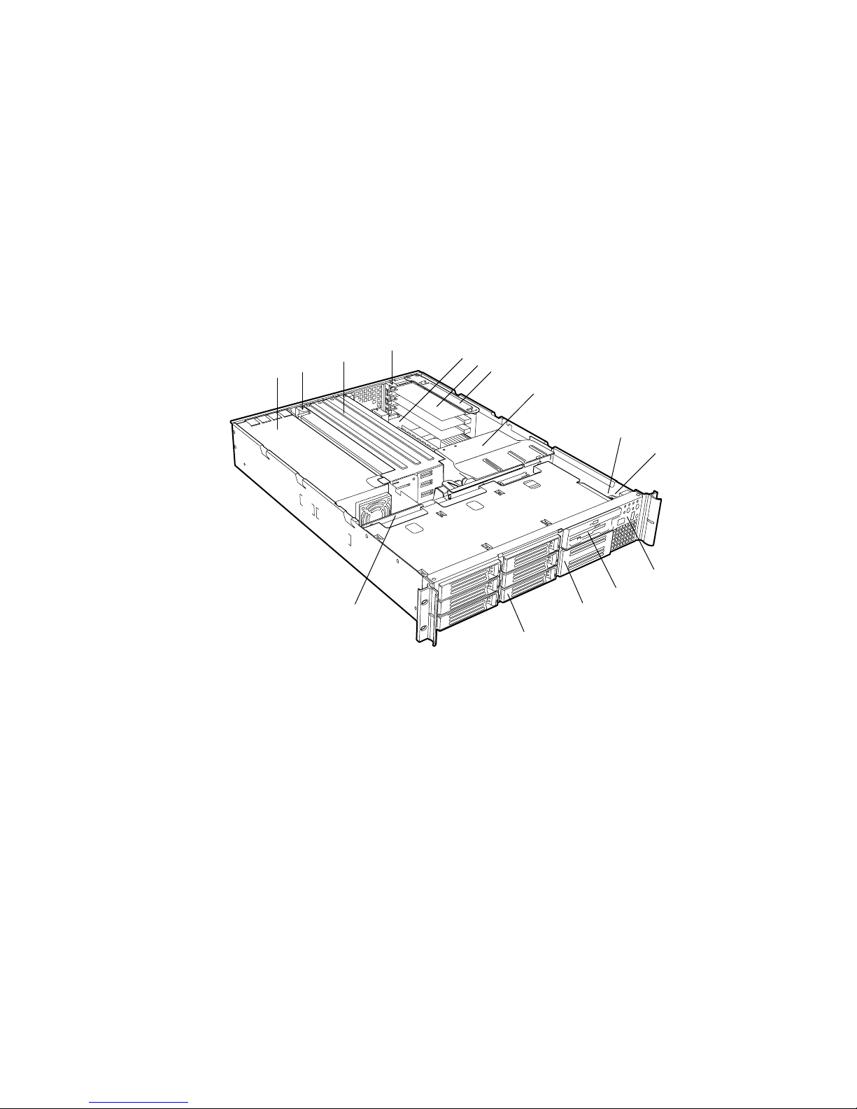
System Components
C
B
A
O
A. Power supply
B. PCI card bracket (full-length)
C. Riser card assembly (full-length)
D. PCI card bracket (low-profile)
E. Server board (accessory to system)
F. PCI add-in card (accessory to
system)
G. Riser card assembly (low-profile)
H. Processor air duct
I. Front panel board
D
Figure 1. System Components
E
F
G
H
I
J
K
L
M
N
OM14080
J. Intrusion switch
K. Control panel
L. Flex bay (optional DVD/CD-ROM drive/FDD
module available)
M. Tape drive bay (tape drive available from
others)
N. Hard drive bay (one of six, accessory to
system)
O. Backplane board
8 Intel SR2300 Chassis Subassembly Product Guide
Page 9
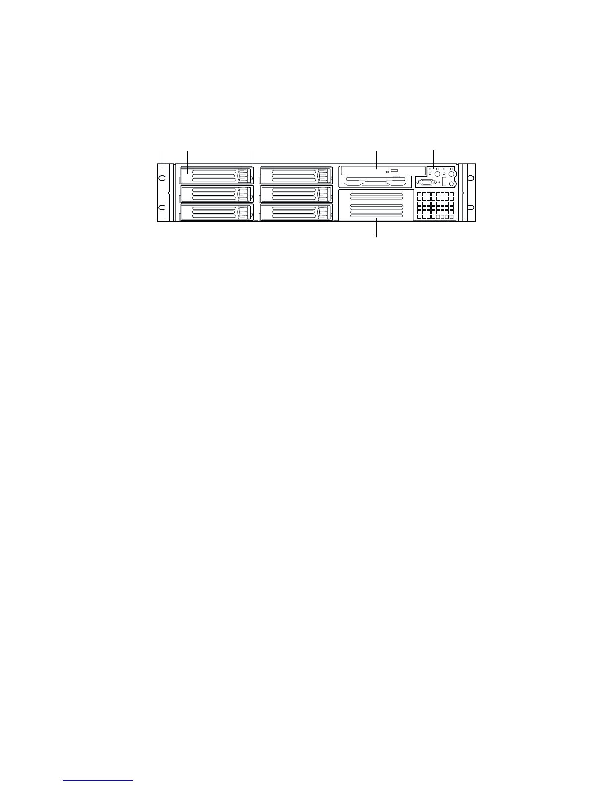
Chassis Front Panel and Peripheral Bays
To access the system controls and peripherals when a front bezel is installed, grasp the bezel and
gently pull it towards you until it unsnaps from the chassis.
A B C D E
F
OM14081
A. Chassis handles (2)
B. Drive bay (1-inch)
C. HDD activity/fault Indicator
D. Flex bay (optional DVD/CD-ROM drive/FDD module
shown installed)
E. Front panel indicator lights
F. Tape drive bay (tape drive not included)
Figure 2. Chassis Front
Chassis Description 9
Page 10
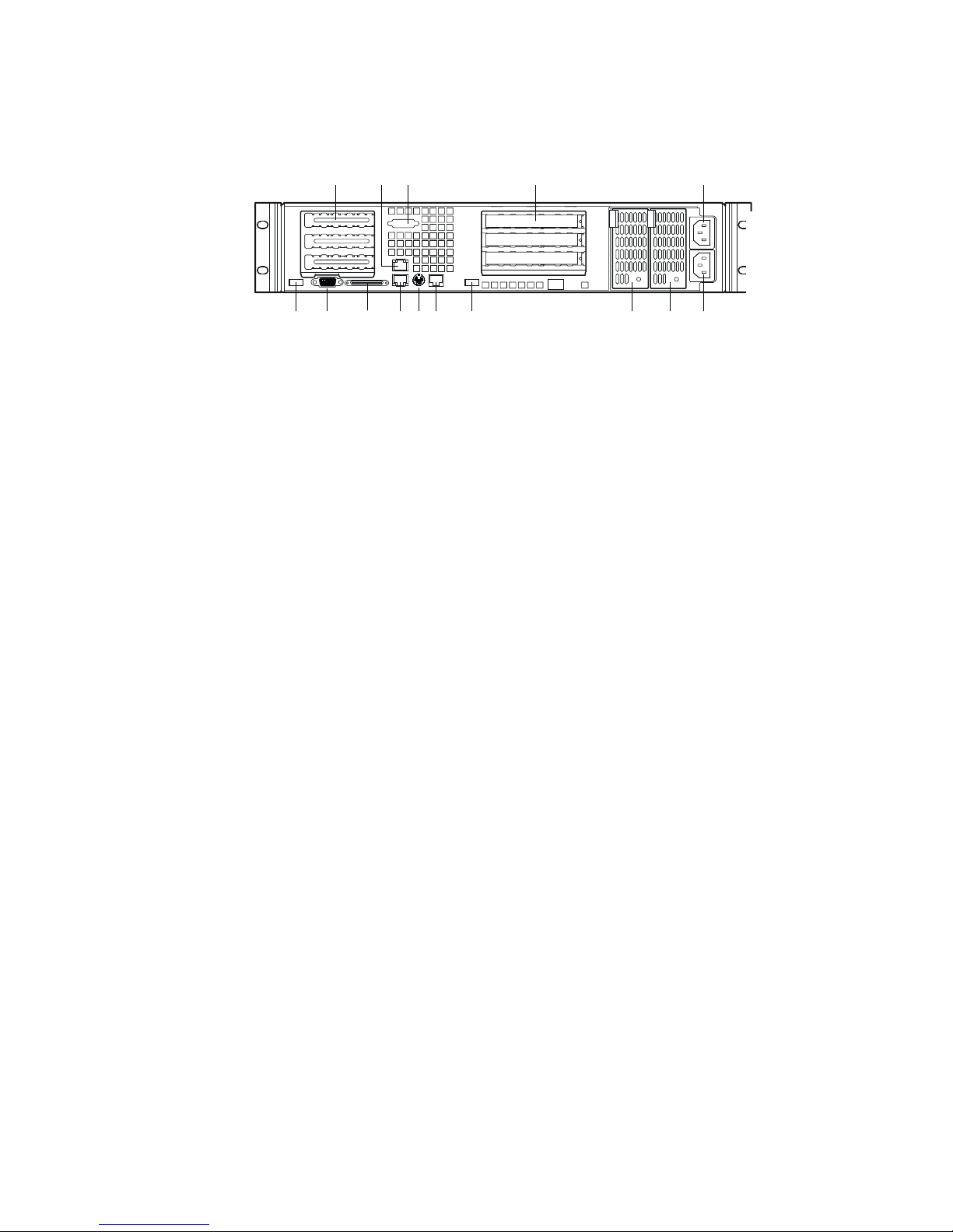
Chassis Back I/O Ports and Features
A CB D E
A. PCI card bracket (low profile) I. USB connector 2
B. RJ45 NIC 2 connector
Green Status LED/Yellow Status LED
C. Serial A port mounting hole
(cable not provided)
D. PCI card bracket (full-height) L. RJ45 NIC 1 connector
E. AC power input (primary)* M. SCSI channel A connector
F. AC power input (redundant)* N. Video connector
G. Power supply module, redundant
(system accessory)*
H. Power supply module, primary*
J. RJ45 serial port
†
K. PS/2
O. USB connector 1
mouse/keyboard connector
(If available)
FGHIJL KMON
OM14082
*480 Watt redundant power supply shown. Your power supply may be different.
Figure 3. Chassis Back
10 Intel SR2300 Chassis Subassembly Product Guide
Page 11
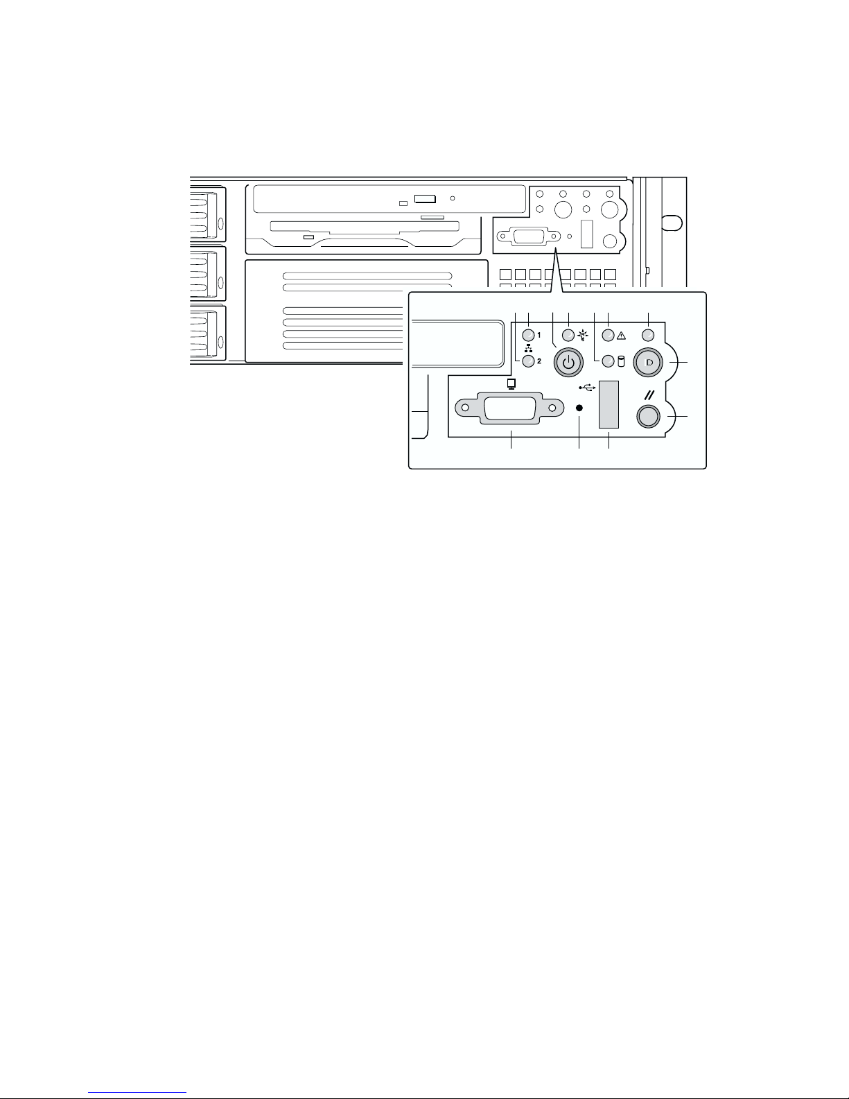
Front Panel Controls and Indicators
Shown with optional DVD/CD-ROM drive/floppy disk drive installed.
L JK
Figure 4. Controls and Indicators
BA F GEDC
H
I
OM14083
A. NIC 2 activity LED G. ID button
B. Power button H. Reset button
C. Power/sleep LED I. USB Connector
D. Fixed disk drive status LED J. NMI button
E. System status LED K. Video Connector
F. ID LED
Chassis Description 11
Page 12
Table 1. Control Button Functions
Power/Sleep button Toggles the system power on/off. Or sleep button for ACPI compliant operating
systems.
Reset button Reboots and initializes the system.
NMI button Pressing the recessed button with a paper clip or pin issues a non-maskable
interrupt and puts the server in a halt state for diagnostic purposes.
ID button Toggles on/off the front panel ID LED and the baseboard ID LED. The baseboard
ID LED is visible through the rear of the chassis and allows you to locate the
server you’re working on from behind a rack of servers.
Table 2. LED Indicator Status
Power/sleep LED Continuous green light indicates the system ha s power applied to it.
(Note 4)
Blinking green light
No light indicates the system does not have power applied to it (other than
5 V standby power).
NIC 1 activity LED
NIC 2 activity LED
Continuous green light indicates activity between the system and the network to
which it is connected.
System status LED Continuous green light indicates the system is operating normally.
Blinking green light indicates the system is operating in a degraded condition.
Continuous amber light
nonrecoverable condition.
Blinking amber light
No light indicates POST/system stop.
Fixed disk drive
status LED
Random blinking green light indicates fixed disk drive activity (SCSI or IDE).
Continuous amber light
No light
(Note 3)
indicates no fixed disk drive activity nor fault (SCSI or IDE).
ID LED Continuous blue light indicates ID button is depressed.
No light indicates ID button is not depressed.
Notes:
1 The Amber status takes precedence over the Green status. When the Amber LED is on or blinking, the Green
LED is off.
2 In order for a hard disk fault indication to occur, either an Intelligent Platform Management Interface (IPMI) based
satellite management controller must send a Set Fault Indication command to the Baseboard Management Controller
(BMC), or the system board must be used with the 2U SR2300 hot swappable backplane.
3 Also off when the system is powered off or in a sleep state.
4 The Power LED sleep indication is maintained on standby by the chipset. If the system is powered down without going
through BIOS, the LED state in effect at the time of power off will be restored when the system is powered on until the
BIOS clears it. If the system is not powered down normally, it is possible that the Power LED will be blinking at the
same time that the System Status LED is off due to a failure or configuration change that prevents the BIOS from
running.
indicates the system is sleeping.
(Note 1)
indicates the system is in a critical or
(Note 1)
indicates the system is in a non-critic al condition.
(Note 2)
indicates fixed disk drive fault (SCSI or IDE).
12 Intel SR2300 Chassis Subassembly Product Guide
Page 13
Peripherals
The chassis provides external bays for peripherals that can be purchased separately and added to the
system. The following describes the available options.
D
B
A
A
E
C
A. Hard drive bays (6)
B. Flex bay (1)
C. DVD/CD-ROM drive/floppy disk drive module
D. Tape drive
E. Hard disk drive
Figure 5. Peripherals
Hot Swappable SCSI Hard Drives
The chassis ships with four drive carriers for mounting SCSI hard drives in the hard drive bays.
For information on how to install these drives, see “Installing a Hard Drive” on page 38.
The SCSI hard drives are hot swappable. When a drive fails, the SCSI backplane detects the
failure, reports it, and powers down the failed drive. The drive fault LED becomes a continuous
amber light. After the failed drive is removed and a new drive is inserted, there is a short wait
before power is applied to the drive and the drive fault LED becomes a random blinking
green light.
OM14084
Chassis Description 13
Page 14

✏ NOTE
Drives can consume up to 17W of power each. Drives must be specified to
run at a maximum ambient temperature of 50 °C.
Flex Bay
The flex bay can be used with either the optional DVD/FDD module, CD-ROM/FDD module, or a
seventh hot swappable SCSI HDD.
The DVD/CD-ROM/FDD module may only be inserted or removed from the flex bay when system
power is turned off. It is NOT hot swappable. For information on installation, see “Installing a
DVD drive/FDD or CD-ROM drive/FDD Module” on page 40.
500 Watt Redundant Power Supply
The power supply consists of the power supply bay and one power supply module. A second
power supply module can be purchased to provide a redundant, 1+1 system. With either
configuration, the power supply provides 500 W of power and is designed to minimize EMI. The
power supply operates within the following voltage ranges and is rated as follows:
• 100-120 V∼ at 50/60 Hertz (Hz); 5.2 A maximum
• 200-240 V∼ at 50/60 Hz; 2.6 A maximum
The power subsystem supports implementation of remote management features including remote
enable that permits power to be activated from a variety of sources.
480 Watt Power Supply
The power supply consists of the power supply; no modules are available. The power supply
provides 480W of power and is designed to minimize EMI. The power supply operates within the
following voltage ranges and is rated as follows:
• 100-120 V∼ at 50/60 Hz; 6.8 A maximum
• 200-240 V∼ at 50/60 Hz; 3.4 A maximum
The power subsystem supports implementation of remote management features including remote
enable that permits power to be activated from a variety of sources.
System Cooling
The chassis includes three 60-mm non-hot-swappable system fans for cooling the processor(s), hard
drives, and add-in cards. A fourth fan may be added to provide cooling redundancy for system
components. The system fans are mounted in a fan module located in the middle of the chassis to
pull cooling air through the chassis. The power supply contains a single fan for cooling.
14 Intel SR2300 Chassis Subassembly Product Guide
Page 15

Chassis Security
To help prevent unauthorized access to the system’s peripherals and control panel, install the
optional front bezel, which provides a key lock. The chassis also includes a preinstalled intrusion
switch for the top access cover that can be monitored by server management software. When the
cover is opened, the switch, located on the front panel board, transmits a signal to the Baseboard
Management Controller (BMC) on the server board, where server management software processes
the signal.
Locking and Unlocking the Front Bezel
To unlock the bezel, insert the key in the lock and turn the lock counterclockwise until it stops
(about a quarter turn). The bezel is now unlocked and can be opened again.
To lock the bezel, insert the key in the lock. Turn the lock clockwise until it stops (about a quarter
turn). The bezel is now locked and cannot be opened.
Chassis Description 15
Page 16

16 Intel SR2300 Chassis Subassembly Product Guide
Page 17

2 Assembling the System
Before the SR2300 can be installed for use, you must assemble the hardware components that make
up your particular system. Additionally, you will want to add any peripherals and add-in cards
purchased for the system. The following procedures help guide you through this assembly process
and create your desired system configuration.
✏ NOTE
To maintain and ensure regulation compliance, the fully integrated system
should be tested, certified and/or documented to illustrate compliance to
the regional regulations and laws for where the product will be sold. The
peripherals and add-in cards chosen for integration should have individual
regulatory approvals.
Before You Begin
Supplies Needed
Before beginning your work, make sure you have the following supplies available:
• Anti-static wrist strap (recommended)
• SR2300 accessory kit (included)
• SE7500WV2 SCSI server board kit
• Processors and memory you purchased separately to add to the server board
• Optional peripherals and add-in cards you want to include in the system
17
Page 18

Installation/Assembly Safety Instructions
Before you start the assembly process, you will need to make sure you follow certain basic safety
precautions.
CAUTION
Only technically qualified persons shall perform integration/servicing of
this chassis sub-assembly.
Follow these guidelines to meet and maintain safety and product regulatory
requirements when integrating this chassis subassembly.
Read and adhere to all of these instructions and the instructions supplied
with this assembly. If you do not follow these instructions, the UL listing
and other regulatory approvals will be void, and the product will most
likely be non-compliant with regional product laws and regulations.
Use Only for Intended Applications
This product was evaluated as Information Technology Equipment (ITE) that may be installed in
offices, schools, computer rooms and similar locations. The suitability of this product for other
Product Categories and Environments other than ITE applications, (such as medical, industrial,
alarm systems, and test equipment) may require further evaluation.
When you integrate this subassembly, observe all warnings and cautions in the Installation Guide.
To avoid injury, be careful of:
• Sharp pins on connectors
• Sharp pins on printed circuit assemblies
• Rough edges and sharp corners on the chassis
• Hot components (like processors, heat sinks, and power supply modules)
• Damage to wires that could cause a short circuit
18 Intel SR2300 Chassis Subassembly Product Guide
Page 19

Checking the Power Cord
WARNING
Do not attempt to modify or use the supplied AC power cords if they
are not the exact type required.
The power supply cords are the main disconnect to AC power. The
socket outlets must be installed near the equipment and readily
accessible.
If the power cords supplied with the system are not compatible with the AC wall outlet in your
region, obtain power cords that meet the following criteria:
• The power cord must be rated for the available AC voltage and have a current rating that is at
least 125% of the current rating of the server.
• The plug on the power cord that plugs into the wall outlet must be a grounding-type male plug
designed for use in your region. It must have certification marks showing certification by an
agency acceptable in your region.
• The connector that plugs into the AC receptacle on the power supply must be an IEC 320,
sheet C13, type female connector.
• In Europe, the cord must be less than 4.5 meters (14.76 feet) long, and it must be flexible
<HAR> (harmonized) or VDE certified cordage to comply with the chassis’ safety
certifications.
Warnings and Cautions
These warnings and cautions apply whenever you remove the chassis cover to access components
inside the server. Only a technically qualified person should integrate and configure the server.
WARNING / BEFORE YOU REMOVE THE ACCESS COVER
Before removing the access cover for any reason, observe these safety
guidelines:
1. Turn off all peripheral devices connected to the server.
2. Turn off the server by pressing the power button on the
front of the chassis. Then unplug all AC power cords from
the chassis or wall outlet.
3. Label and disconnect all peripheral cables and all
telecommunication lines connected to I/O connectors or
ports on the back of the chassis.
4. Provide some electrostatic discharge (ESD) protection by
wearing an antistatic wrist strap attached to chassis
ground—any unpainted metal surface—when handling
components.
Assembling the System 19
Page 20
WARNING
The power button on the front panel DOES NOT turn off the
AC power. To disconnect power from the server, you must unplug all
AC power cords from the wall outlet or the chassis.
WARNING
Hazardous electrical conditions may be present on power, telephone,
and communication cables. Turn off the server and disconnect the
power cords, telecommunications systems, networks, and modems
attached to the server before opening it. Otherwise, personal injury or
equipment damage can result.
WARNING
Do not open the power supply. Hazardous voltage, current and energy
levels are present inside the power supply. Refer servicing of the
power supply to qualified technical service personnel.
20 Intel SR2300 Chassis Subassembly Product Guide
Page 21
Installing System Components
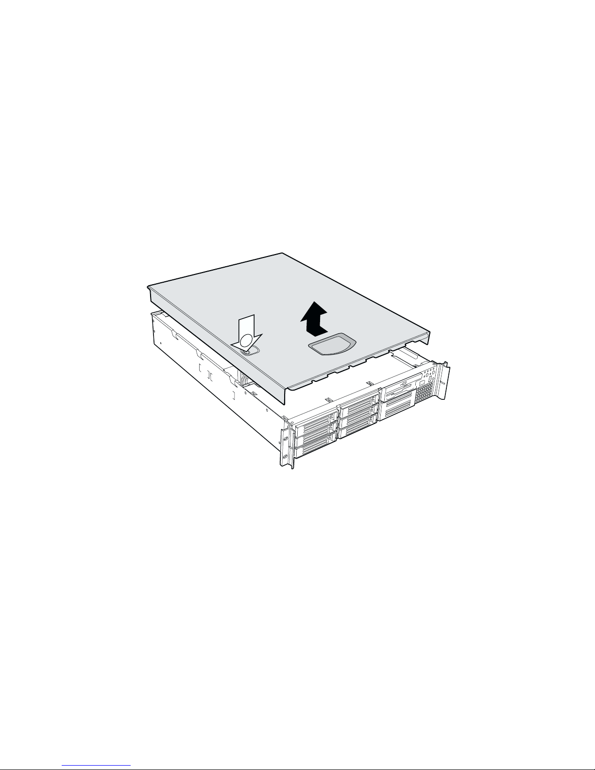
Remove the Cover
1. While pressing the blue latch button (A) with your left thumb, slide the top cover back using
the heel of your right hand on the blue pad.
✏ NOTE
A non-skid surface or a stop behind the chassis may be needed if attempting
to remove the top cover on a flat surface.
2. Set the cover aside and away from the immediate work area.
A
Assembling the System 21
Figure 6. Removing the Cover
OM14086
Page 22
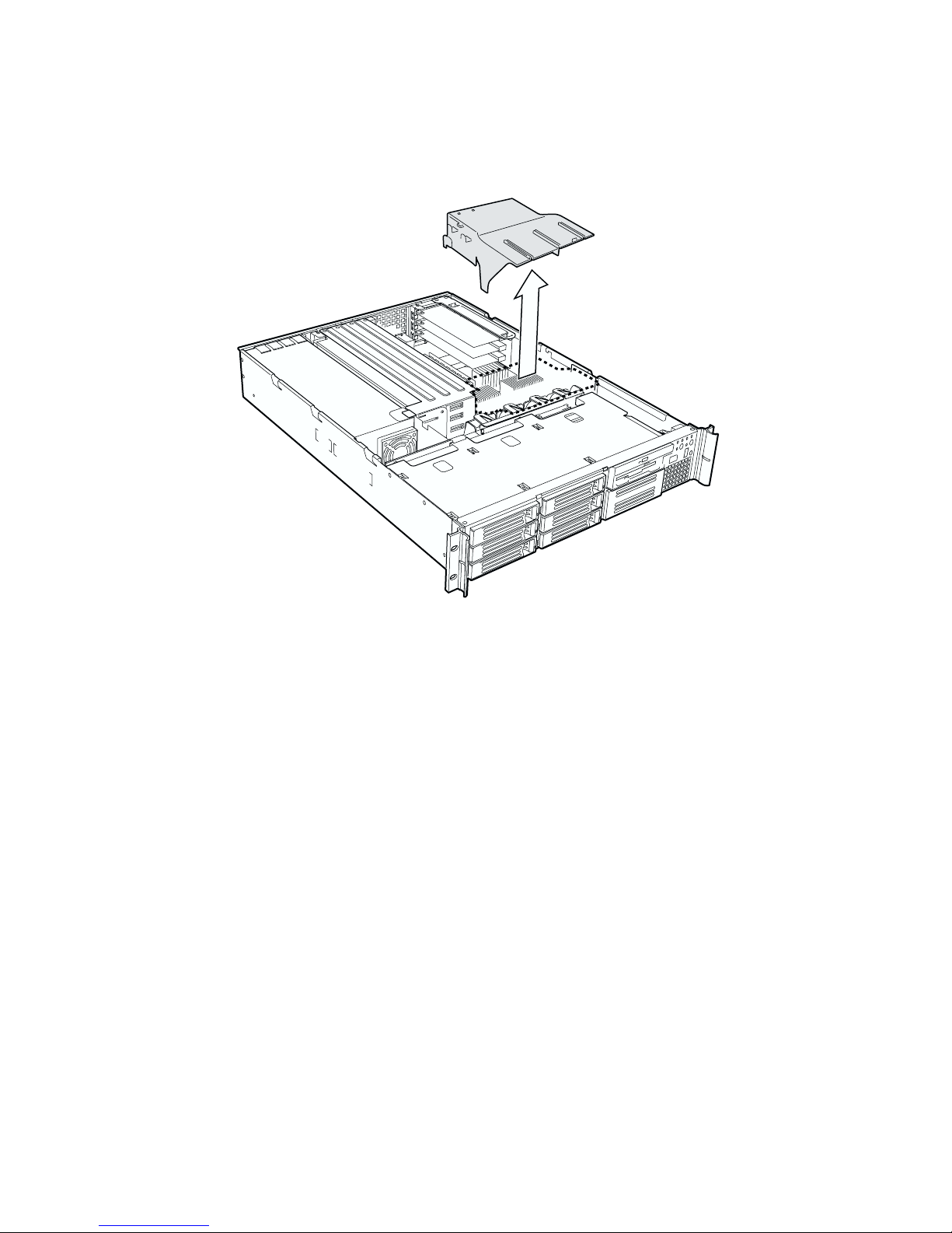
Remove the Processor Air Duct
Lift the processor air duct out of the chassis.
Figure 7. Removing the Processor Air Duct
OM14583
22 Intel SR2300 Chassis Subassembly Product Guide
Page 23
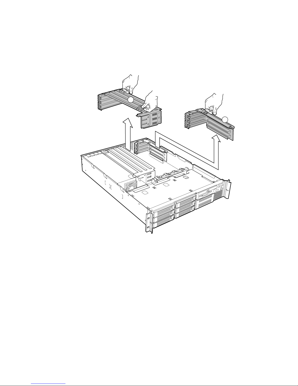
Remove the Riser Cards
1. Insert your finger in the plastic loop. On riser card (A), also grasp the opposite end at (C).
2. Pull straight up and remove the riser card from the chassis.
3. Discard the protective blocks.
A
B
OM14087
Figure 8. Removing a Riser Card
Assembling the System 23
Page 24
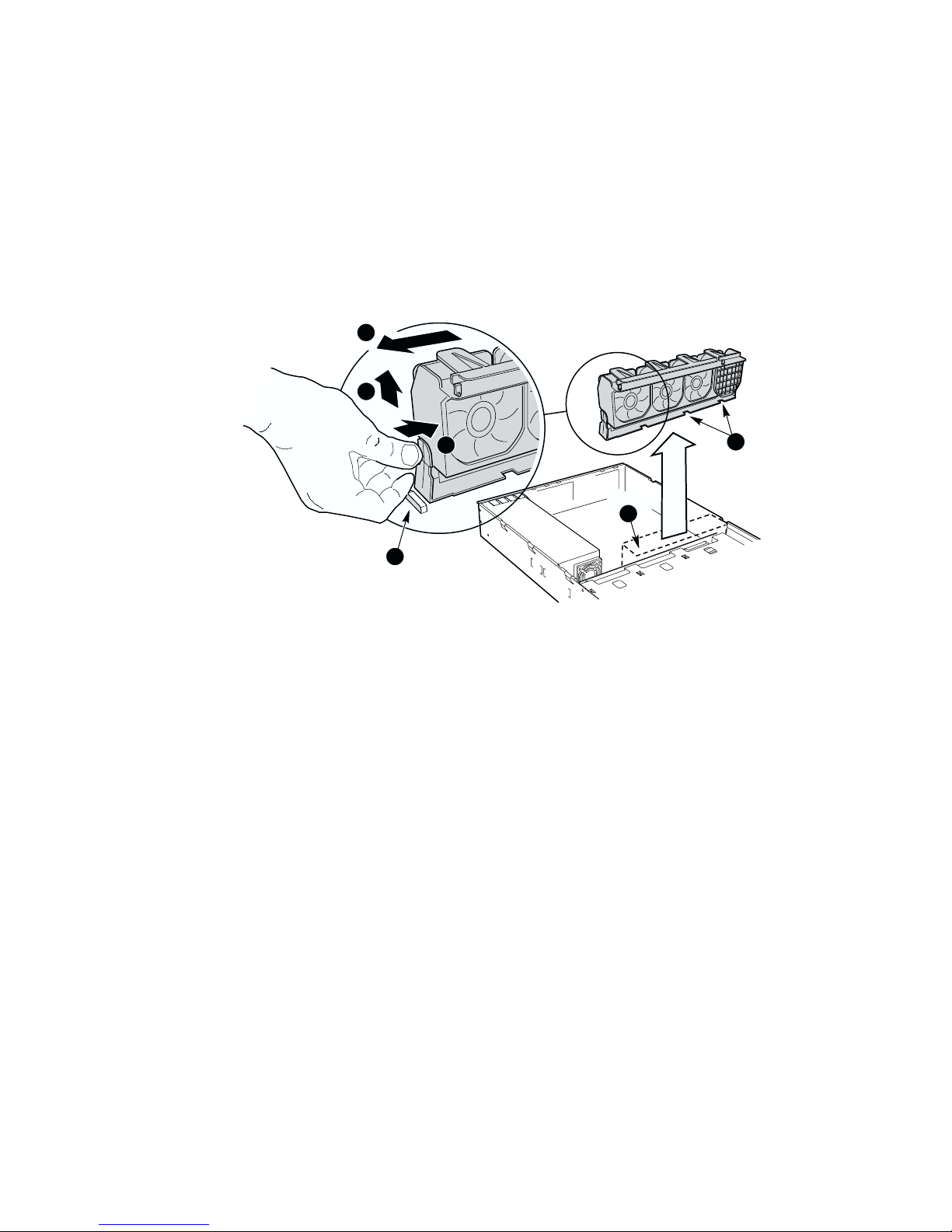
Remove the Fan module
1. Lift the processor duct out of the chassis.
2. If it is installed, remove the 100-pin flex circuit.
3. At the end of the fan module closest to the chassis centerline, push on the tab to release it from
the chassis (A).
4. While pushing on the tab, lift up on the module to clear the retention stub.
5. Slide the module towards the power supply until it comes free.
6. Lift the fan module out of the chassis.
3
2
1
B
A
Figure 9. Removing the Fan module
C
OM14088
24 Intel SR2300 Chassis Subassembly Product Guide
Page 25

Install the Server Board
CAUTION
Do not install any server board support bumpers in the SR2300 chassis.
System components must be installed in the order presented below. If
installed in a different order, component damage may occur.
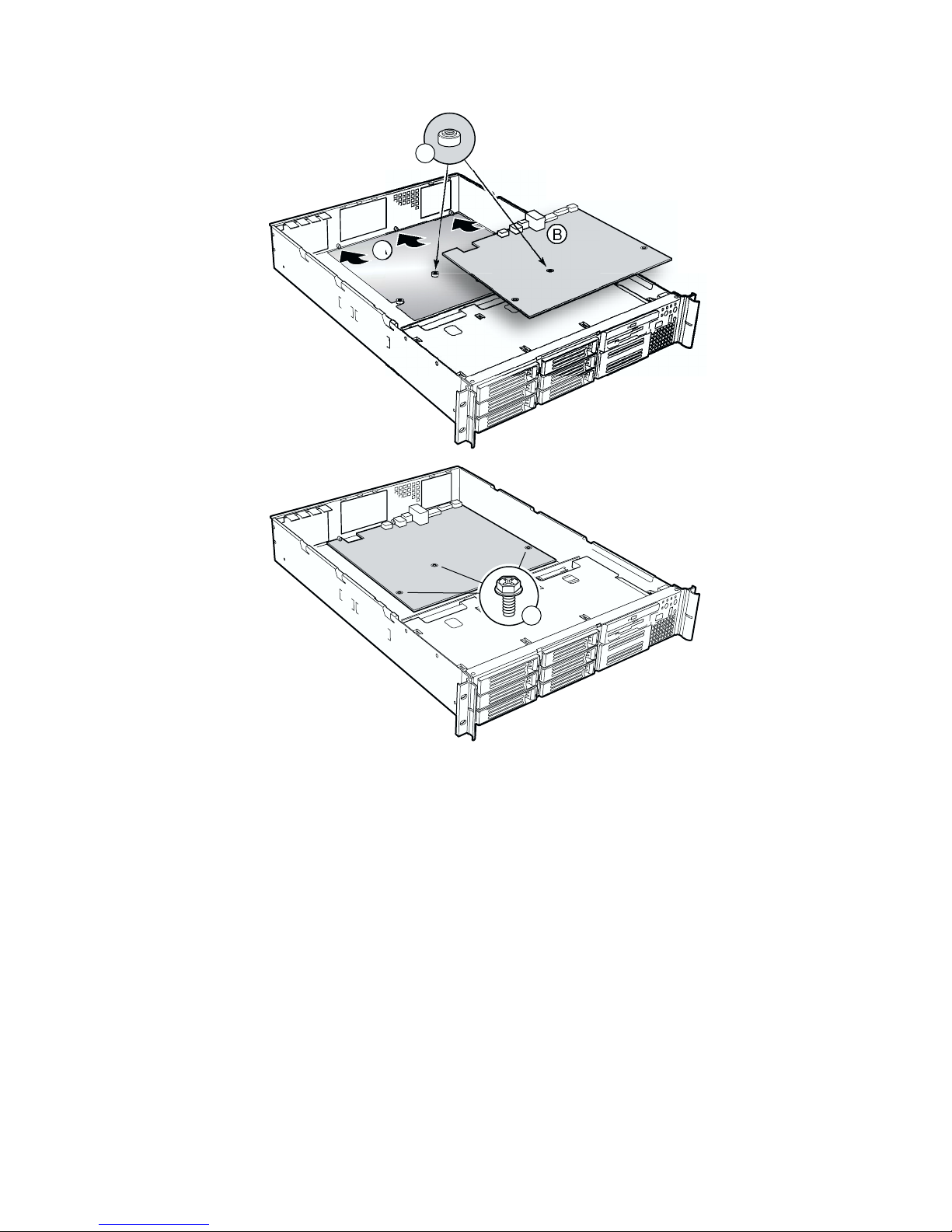
1. Ensure that the insulator sheet is seated securely over the standoffs, is laying flat on the
chassis floor, and that the edge of the sheet is seated below the studs in the rear chassis wall.
(Figure 10, A.)
2. Remove the server board from its packaging and antistatic bag.
3. While placing the board on the chassis standoffs, carefully position the board I/O connectors
(Figure 10, B) in the rear chassis I/O openings.
4. Adjust board position so that the mounting holes rest securely on the corresponding
shouldered standoffs (Figure 10, C).
5. Attach the board to the chassis using the three screws shipped in the chassis accessory kit
(Figure 10, D).
Assembling the System 25
Page 26
C
D
OM14090
Figure 10. Mounting the Server Board SE7500WV2
26 Intel SR2300 Chassis Subassembly Product Guide
Page 27
6. Install processors and memory, following the directions on the Intel Server Board
SE7500WV2 Quick Start User Guide.
7. If you only install one processor, you must install the processor air dam.
a. Attach processor retention piece (B) to the server board (C) using the provided
screws (A).
b. Put the air dam(D) into place.
A
B
C
D
Figure 11. Installing the Processor Air Dam
OM14579
Assembling the System 27
Page 28

Routing Cables
J
1
8
ATA66
D
H
B
A
2 2
I
1. Power Supply
2. SCSI Hard Disk Drives
3. DVD/CD-ROM/FDD module
4. Tape Drive (optional)
5. Front Panel Board
6. Fan Module
7. SCSI Backplane (shown horizontal for clarity)
8. Server Board
A. To backplane power connector from power
supply
B. To server board primary power connector
from power supply
Figure 12. Cable Routing
G
6
E
Cable Legend
Data
Power
C
7
F
2
or
3
4
K
5
OM14091
C. Floppy/FP/IDE flex circuit cable from server
board to backplane
D. SCSI cable from server board to backplane
E. USB ribbon cable from front panel board to
server board
F. Ribbon cable from front panel board to backplane
G. Fan module to server board fan connectors (2)
H. To server board auxiliary signal connector from
power supply
I. To server board auxiliary power connector from
power supply
J. Serial cable from server board to knockout on
back of chassis
28 Intel SR2300 Chassis Subassembly Product Guide
Page 29

Connect Power Cables
1. Verify that the P6 backplane power cable is routed from the power supply to the backplane
board and is connected to the white 6-pin connector.
2. Connect the main server board power cable to the white 24-pin connector on the server board.
Firmly press the two connectors together until they are fully seated.
B
B
A
OM14616
Figure 13. Connecting the Main Power Cable
Install the Fan module
CAUTION
When installing the fan module, avoid pinching cables routed in the area.
1. Note the raised tabs on the chassis floor and the corresponding holes in the bottom of the fan
module.
2. Lower the fan module until it is just above the chassis floor.
3. Align the holes in the fan module with the raised tabs on the chassis and lower the fan module
onto the floor.
4. While pressing down on the fan module, slide it in the direction of arrow (2) until the latch
snaps into place.
Assembling the System 29
Page 30

2
C
1
3
A
Figure 14. Installing the Fan module
5. Connect the fan power cables to the server board (Figure 15).
B
OM14577
Figure 15. Connecting Fans to the Server Board
30 Intel SR2300 Chassis Subassembly Product Guide
A
OM14586
Page 31

Connect Flex Circuit Cable
1. Remove the flex circuit cable from the cable bag in the accessory kit. Connect the end marked
“P1-Motherboard” to the floppy/front panel/IDE connector on the server board. Route the
cable to the backplane board and connect the other cable end to the matching connector on the
backplane.
B
C
A
OM14584
Figure 16. Connecting the Flex Circuit Cable
CAUTION
Ensure that each cable connector is properly seated in the board connector.
The connector should be parallel to its board connector and not cocked to one
side. If in doubt, remove, reinsert, and recheck.
Serverboard
P1
!
Make sure connectors
are FULLY seated
Figure 17. Floppy/FP/IDE Cable Caution
2. Install the flex circuit cable retention clip. It snaps into place over the backplane and flex
circuit cable.
FLOPPY-FP-IDE CABLE
A95680-002
OM14656
HSBP
P2
Assembling the System 31
Page 32

C
A
B
A
TB
Figure 18. Installing the Flex Circuit Retention Clip
Connect Auxiliary Power Cables
1. Connect the auxiliary power cable to the 8-pin auxiliary power connector on the server
board (A).
2. Connect the signal cable to the 5-pin signal connector on the server board (B).
B
OM14617
D
Figure 19. Connecting the Auxiliary Power Cables
32 Intel SR2300 Chassis Subassembly Product Guide
A
OM14585
Page 33

Finish Cable Routing
1. Connect the USB cable to the USB connector on the front panel. Route the cable along the top
of the fan module and connect it to the server board. Make sure the cable does not lay on top of
the corner of the backplane or it will get damaged when you install the top cover.
2. Install the processor duct.
Figure 20. Installing the Processor Duct
OM14615
Assembling the System 33
Page 34

3. If it isn’t installed, install the power supply air baffle. All cables from the power supply should
route through the notch in the bottom of the baffle.
A
B
OM14582
Figure 21. Installing the Power Supply Air Baffle
4. Connect the SCSI cable to the SCSI connector on the server board. Route the cable between
the memory connectors and the full height PCI riser, through the clips on the side of the
processor duct, through the notch in the top of the power supply air baffle, to the connector on
the backplane board.
NOTE
✏
It may be easier to route the SCSI cable after the full length PCI riser card is
installed.
5. Ensure that the front panel cable is connected to the front panel board, routed over USB cable
to the backplane, and connected to the matching connector.
Installing Peripherals
Peripherals and add-in cards are not included in your system and must be purchased separately.
The following sections describe how to install PCI add-in cards, hard disk drives, a DVD/CD-ROM
drive/floppy disk drive, and a tape drive.
34 Intel SR2300 Chassis Subassembly Product Guide
Page 35

Installing a PCI Card on a Riser Card
The riser card nearest the chassis sidewall (see Figure 24, B, on page 37) supports three Low
Profile (LP) PCI add-in cards. The riser card on the chassis centerline (see Figure 24, A, on
page 37) supports three full-length, full-height PCI add-in cards or three LP cards (an LP card must
be equipped with a standard full-height PCI mounting bracket).
PCI add-in cards must be installed on a riser card while the riser card is removed from the chassis. If you
do not have PCI cards to install, proceed to page 37, “Installing the Riser Cards on the Server
Board”.
✏ NOTES
If you install a NIC in the top slot of either the low profile riser or full height
riser, you may encounter difficulty removing network cables connected to the
card.
1. Open the retainer clip (Figure 22 or Figure 23, A) and remove the desired filler panel from the
rear retention bracket (B) of the riser card.
If your full-length card has a card guide attached to the end opposite the metal bracket,
remove the guide.
2. Insert the edge connector of the PCI card into the desired slot of the riser card (D) while
inserting the end of the card’s metal bracket in opening (C).
If you are installing a full-length card, insert the end opposite the metal bracket into the
full-length card lock.
3. Firmly push the PCI card’s edge connector into the riser card slot until it is fully seated.
4. Close the retainer clip (E). Ensure the clip is latched.
B
A
D
Figure 22. Installing a Low-Profile PCI Card in a Riser Card
Assembling the System 35
C
E
OM14096
Page 36

A
D
B
C
OM14097
Figure 23. Installing a Full-Length PCI Card in a Riser Card
36 Intel SR2300 Chassis Subassembly Product Guide
Page 37

Installing the Riser Cards on the Server Board
1. Align the riser card connector with the server board slot.
2. Firmly press the riser card straight down until it is fully seated in the server board slot. Make
sure the tabs on the rear retention bracket are aligned with the holes in the chassis.
3. Install the other riser card in the same manner.
A
B
Assembling the System 37
A. Full-length riser card
B. Low-profile riser card
Figure 24. Installing the Riser Cards
OM14098
Page 38

Installing a Hard Drive
The server can support up to seven hot swappable hard drives: six hard drives in the drive bays,
plus one in the flex bay.
CAUTION
To allow proper airflow and server cooling, all drive bays must contain either
a carrier with a hard drive installed or a carrier with an air baffle installed.
1. If present, remove the front bezel.
2. If the drive carrier is installed in the drive bay, remove it.
3. Remove the air baffle (Figure 25, A) from the drive carrier by removing the four screws (B)
from the slide track (C).
4. Store the air baffle for future reinstallation in the event you must operate your server without a
drive in one of the bays.
A
B
C
OM14099
Figure 25. Removing an Air Baffle from a Drive Carrier
38 Intel SR2300 Chassis Subassembly Product Guide
Page 39

5. Remove the hard drive from its wrapper and place it on an anti-static surface.
6. Set any jumpers and/or switches on the drive according to the drive manufacturer’s
instructions.
7. With the drive circuit-side-down (Figure 26, A), position the connector end (E) so that it is
facing the back of the carrier (B).
8. Align the holes in the drive to the holes in the drive carrier slide track (C), insert the screws (D)
that you previously removed, and attach the carrier to the drive.
E
A
B
C
D
OM14100
Figure 26. Attaching the Drive to the Carrier
9. Slide the carrier/drive all the way into the drive bay with the retention lever in the fully open
position.
10. Push the retention lever closed to secure the carrier/drive in the bay.
11. Reinstall a carrier/air baffle in any bays where you are not installing a carrier/drive.
Assembling the System 39
Page 40

Installing a DVD drive/FDD or CD-ROM drive/FDD Module
Your server does not come with a DVD drive, CD-ROM drive or floppy disk drive. As an
accessory, Intel offers slim-line DVD drive/FDD and CD-ROM drive/FDD modules that you may
purchase and install in the flex bay.
1. Remove the filler panel (Figure 27, A) and plug (B) from the front of the chassis.
2. Ensure the handle bar (C) on the front of the module is rotated to the down position.
3. Insert the module into the flex bay and slide it back until you feel the connectors touch.
4. With your thumbs positioned above the handle bar indentations (D), push the module in until it
locks in place.
B
A
Figure 27. Installing a DVD/CD-ROM drive/FDD Module
40 Intel SR2300 Chassis Subassembly Product Guide
D
C
D
OM14101
Page 41

Finishing Installation
Installing a Serial A port in the Rear I/O
Using a standard DH-10 to DB-9 COM cable, you may install a Serial A port in the opening
provided in the rear I/O (see Figure 3, C, on page 10). Connect the other end to the COM 1 serial
port header on the server board (see the documentation that shipped with your server board).
Install the Cover
1. Place the cover over the chassis.
2. Slide it forwards until it latches into place.
Installing the Power Cord and Strain Relief Strap
✏ NOTE
If you are placing the server in a rack, wait to install the power cord until
after the server is in the rack.
1. Attach the strain relief strap to the chassis (A).
2. Plug the power cord into the power supply but not into the power source.
3. Insert the power cord into the plastic loop (B) of the strain relief.
4. Pull the plastic band (C) until it tightens around the power cord.
To release the plastic loop and free the cord, squeeze the release lever (D).
A
A
B
D
C
Figure 28. Installing the Power Cord and Strain Relief Strap
OM14095
Assembling the System 41
Page 42

Install the Bezel
Place the bezel between the chassis handles and push it toward the front of the chassis until it snaps
into place.
Figure 29. Installing the Bezel
OM14108
42 Intel SR2300 Chassis Subassembly Product Guide
Page 43

3 Installing the System in a Rack
Your SR2300 chassis comes equipped with a rack mount kit that can be configured for front-mount,
mid-mount, or 4-post racks. An optional slide rail kit may be purchased separately.
Each kit contains instructions for installation into a rack or cabinet. If you need additional copies,
the order numbers are:
• SR1200 and SR2300 Rail Kit Installation Guide—A61347-003
• SR1200 and SR2300 Bracket Kit Installation Guide—A61346-004
Equipment Rack Precautions
CAUTION
ANCHOR THE EQUIPMENT RACK: The equipment rack must be
anchored to an unmovable support to prevent it from falling over when one
or more servers are extended in front of it on slide assemblies. The
equipment rack must be installed according to the manufacturer's
instructions. You must also consider the weight of any other device installed
in the rack.
MAIN AC POWER DISCONNECT: You are responsible for installing an
AC power disconnect for the entire rack unit. This main disconnect must be
readily accessible, and it must be labeled as controlling power to the entire
unit, not just to the server(s).
GROUNDING THE RACK INSTALLATION: To avoid the potential for
an electrical shock hazard, you must include a third wire safety grounding
conductor with the rack installation. If server power cords are plugged into
AC outlets that are part of the rack, then you must provide proper grounding
for the rack itself. If server power cords are plugged into wall AC outlets,
the safety grounding conductor in each power cord provides proper
grounding only for the server. You must provide additional, proper
grounding for the rack and other devices installed in it.
OVER CURRENT PROTECTION: The server is designed for an AC line
voltage source with up to 20 amperes of over current protection. If the power
system for the equipment rack is installed on a branch circuit with more than
20 amperes of protection, you must provide supplemental protection for the
server. If more than one server is installed in the rack, the power source for
each server must be from a separate branch circuit.
43
Page 44

CAUTION
Temperature: The operating temperature of the server, when installed in an
equipment rack, must not go below 5 °C (41 °F) or rise above 35 °C (95 °F).
Extreme fluctuations in temperature can cause a variety of problems in your
server.
Ventilation: The equipment rack must provide sufficient airflow to the front
of the server to maintain proper cooling. It must also include ventilation
sufficient to exhaust a maximum of 2110 Btu's per hour for a fully loaded
SR2300 server.
It is important to note that this is the maximum, and a minimum or typical
system could be much less. You may want to calculate the BTU/hr more
accurately for your configuration. An extra 500 BTU/hr over many systems
would translate into a large error calculating air conditioning capacity.
44 Intel SR2300 Chassis Subassembly Product Guide
Page 45

4 Working Inside Your Server
This chapter describes how to replace components in your server after it has been set up. All
references to left, right, front and rear are based on the reader facing the front of the chassis.
Tools and Supplies Needed
• Antistatic wrist strap (recommended)
Safety: Before You Remove the Cover
Before removing the system cover to work inside the system, observe these safety guidelines:
1. Turn off all peripheral devices connected to the system.
2. Turn off the system by pressing the power button on the front of the system. Then unplug the
AC power cord from the system or wall outlet.
3. Label and disconnect all peripheral cables and all telecommunication lines connected to
I/O connectors or ports on the back of the system.
4. Attach a wrist strap to a chassis ground of the system—any unpainted metal surface—before
handling components.
45
Page 46

Warnings and Cautions
These warnings and cautions apply whenever you remove the chassis cover to access components
inside the server. Only a technically qualified person should integrate and configure the server.
Lithium Battery Replacement
CAUTION
Refer to technically qualified persons only for replacement of battery.
The following warning is provided on the server board configuration label,
which is provided with the Intel server board boxed product. There is
insufficient space on the server board to place this label. Therefore, the label
must be placed permanently on the inside of the chassis, as close to the
battery as possible.
WARNING
Danger of explosion if battery is incorrectly replaced. Replace with only
the same or equivalent type recommended by the manufacturer.
Dispose of used batteries according to the manufacturer’s instructions.
ADVARSEL!
Lithiumbatteri - Eksplosionsfare ved fejlagtig håndtering. Udskiftning
må kun ske med batteri af samme fabrikat og type. Levér det brugte
batteri tilbage til leverandøren.
ADVARSEL!
Lithiumbatteri - Eksplosjonsfare. Ved utskifting benyttes kun batteri
som anbefalt av apparatfabrikanten. Brukt batteri returneres
apparatleverandøren.
VARNING
Explosionsfara vid felaktigt batteribyte. Använd samma batterityp eller
en ekvivalent typ som rekommenderas av apparattillverkaren. Kassera
använt batteri enligt fabrikantens instruktion.
VAROITUS
Paristo voi räjähtää, jos se on virheellisesti asennettu. Vaihda paristo
ainoastaan laitevalmistajan suosittelemaan tyyppiin. Hävitä käytetty
paristo valmistajan ohjeiden mukaisesti.
46 Intel SR2300 Chassis Subassembly Product Guide
Page 47

Replacing Components
Replacing a Hard Drive
CAUTION
To allow proper airflow and cooling during operation, all drive bays must
contain either a carrier/drive or a carrier with air baffle installed.
1. Before removing the cover to work inside the system, observe the safety guidelines on page 45.
2. Remove the bezel from the front of the chassis.
3. Pull the retention lever (A) toward you until the tab end (B) of the lever is free of the
housing slot (C).
4. Pull the carrier/drive forward and out of the drive bay.
C
B
Figure 30. Removing a Carrier and Hard Drive from a Drive Bay
A
OM14109
5. Remove the hard drive from the carrier (A) by removing the four screws (D) from the slide
track (C). Lift the drive out of the carrier (B).
6. Remove the new hard drive from its wrapper and place it on an anti-static surface.
Working Inside Your Server 47
Page 48

7. Set any jumpers and/or switches on the drive according to the drive manufacturer’s
instructions.
A
C
D
Figure 31. Removing a Hard Drive from a Carrier
OM14110
B
8. Install the new drive in the carrier and the carrier/drive into the drive bay (see “Installing a
Hard Drive” on page 38).
9. Reinstall a carrier/air baffle in any bays where you are not reinstalling a carrier/drive.
48 Intel SR2300 Chassis Subassembly Product Guide
Page 49

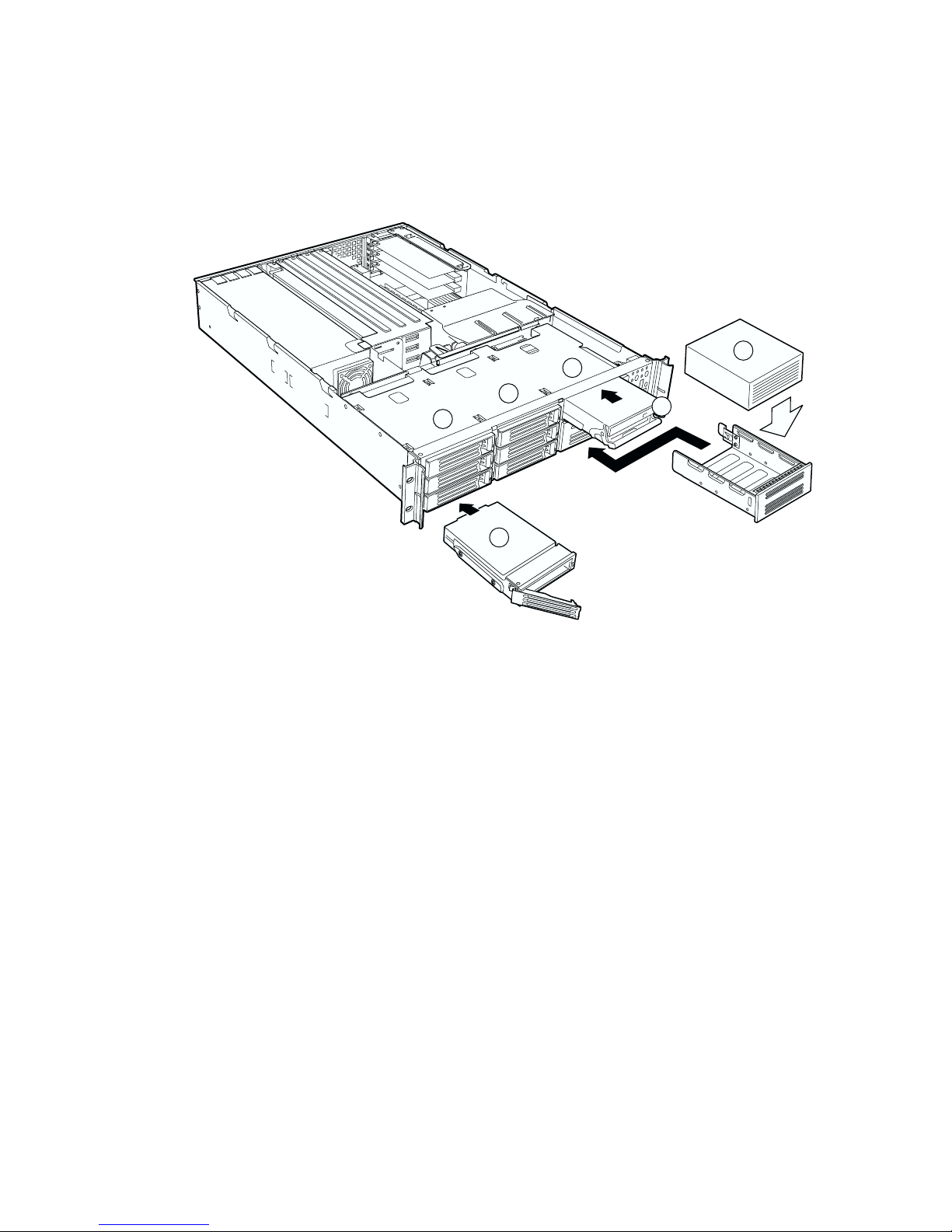
Replacing a DVD/CD-ROM drive/FDD Module
CAUTION
A DVD/CD-ROM drive/FDD module is NOT hot swappable. Before
replacing it, you must first take the server out of service, turn off all
peripheral devices connected to the system, turn off the system by pressing
the power button, and unplug the AC power cord from the system or wall
outlet.
1. Remove the bezel from the front of the chassis.
2. Rotate the handle bar (A) up about ¼-inch (6-mm) to unlatch the module from the bay.
3. Grasp the handle bar at both ends and firmly pull out to disengage the connector. (When you
first pull, resistance will be high until the connector disengages.)
4. Slide the module out of the flex bay.
5. On the replacement module, rotate the handle bar down.
6. Insert the replacement module into the flex bay and slide it back until you feel the connectors
touch.
7. With your thumbs positioned above the handle bar indentations (B), push the module in until it
locks in place.
8. Reinstall the bezel.
Figure 32. Replacing a DVD/CD-ROM drive/FDD Module
Working Inside Your Server 49
B
A
B
OM14111
Page 50

Replacing a PCI Add-in Card
If you will be replacing a low-profile PCI add-in card, see Figure 33 on page 51.
If you will be replacing a full-length PCI add-in card, see Figure 34, page 52.
1. Before removing the cover to work inside the system, observe the safety guidelines on page 45.
2. Insert your finger in loop A and remove the riser card assembly that contains the add-in card
you desire to replace.
If you are removing a full-length card, also grasp the opposite end.
3. Open the retainer clip on the riser card retention bracket.
4. Pull the PCI card out of the riser card assembly.
5. Insert the edge-connector of the replacement PCI card into the slot of the riser card while
inserting the end of the PCI card’s metal bracket in opening.
If you are installing a full-length card, also insert the end of the card opposite the metal
bracket into the slots of the full-length card lock.
7. Firmly push the PCI card’s edge-connector into the riser card slot until it is fully seated.
8. Close the retainer clip and ensure it is latched.
9. Insert the riser card connector in the server board slot while aligning the tabs on the rear
retention bracket with the holes in the chassis.
10. Firmly press the riser card straight down until it is seated in the server board slot.
50 Intel SR2300 Chassis Subassembly Product Guide
Page 51

A
B
OM14112
Figure 33. Removing the Low-Profile PCI Riser Card
Working Inside Your Server 51
Page 52

A
B
Figure 34. Removing the Full-Length PCI Riser Card
OM14113
52 Intel SR2300 Chassis Subassembly Product Guide
Page 53

Replacing a 500 Watt Power Supply Module
The 500 Watt redundant power supply system consists of the power supply bay and either one or
two power supply modules. The optional second module provides a redundant, 1+1 system.
CAUTION
If you do not have the second, redundant power supply module, you must
take the server out of service before replacing the single module.
1. Squeeze the module handle to depress the latch (Figure 35, A) that is the right side of the
handle.
2. Rotate the handle down (B) while pulling the module toward you (C). As you pull the module
out, support the module with your free hand.
3. Insert a new power supply module in the bay.
4. Grip the module handle, rotate it down, and push the module into the bay.
5. When the module is nearly all of the way in, the handle will rotate up. At this time, push firmly
on the front of the handle to lock the latch.
6. The power supply module is now functional and the power supply fault indicator should
not be lit.
A
Figure 35. Replacing a Power Supply Module
B
OM14114
C
Working Inside Your Server 53
Page 54

Replacing a Power Supply Cage
The following procedures apply to both the redundant and the non-redundant power supply.
1. Unplug the power cord from the power source.
2. At the rear of the server, release the strain relief(s) and unplug the power cord(s) from the
power supply.
3. Remove the power supply modules (redundant power supply only).
4. Remove the chassis cover.
5. Remove the full-height PCI riser card.
6. Remove the fan module.
7. Disconnect and remove all data cabling necessary to gain access to the power cables.
8. Disconnect the main power connector from the server board.
9. Disconnect all other power cables from their devices.
10. At the rear of the chassis, remove the two screws (A) that secure the power supply.
NOTE
✏
In Figure 36, B, the power cables are not shown for clarity.
11. At the fan end of the power supply, remove the screw (C) that attaches the power supply to the
standoff in the chassis floor.
A
B
D
E
C
54 Intel SR2300 Chassis Subassembly Product Guide
Figure 36. Replacing a Power Supply Cage
OM14115
Page 55

12. Lift the fan end of the power supply above the chassis standoff and slide it toward the front of
the server (D). Lift the power supply out of the chassis (E).
13. Place the new power supply in the chassis and slide it to the rear as far as it will go.
14. Install the two screws at the rear of the chassis and the one screw at the fan end of the power
supply.
15. Plug the main power connector into the server board.
16. Connect all other power cables to their devices.
17. Install the fan module and connect the fan power cables to the server board.
18. Install the full-height PCI riser card.
19. Route and connect all cables.
CAUTION
Carefully route cables in their original paths to minimize airflow blockage
and cooling problems.
20. Install the chassis cover.
21. Connect the power cord(s) to the power cord receptacle(s) and plug the cord(s) back into the
power source.
Working Inside Your Server 55
Page 56

Installing a Redundant Fan
1. Before removing the cover to work inside the system, observe the safety guidelines on page 45.
2. Remove the cover from the chassis.
3. Remove the full-height PCI riser card.
4. Remove the flex circuit cable retention clip.
5. Disconnect the flex circuit cable from the backplane.
6. At the end of the fan module closest to the chassis centerline, push on the tab to release it from
the chassis (A).
7. While pushing on the tab, lift up on the module to clear the retention stub.
8. Slide the module towards the power supply until it comes free.
9. Lift the fan module out of the chassis.
3
2
1
A
Figure 37. Removing the Fan module
10. Remove the fan blank from the fan module.
A
C
B
OM14088
B
56 Intel SR2300 Chassis Subassembly Product Guide
Figure 38. Removing the Fan Blank
OM14587
Page 57

11. Connect the new fan’s cable to the connector on the fan module.
12. Insert the top of a new fan into the fan module and rotate the bottom in until tab (B) locks it
in place.
A
C
B
OM14613
Figure 39. Installing the New Fan
13. Align the holes in the fan module with the raised tabs on the chassis and lower the fan module
onto the chassis floor.
14. Slide the fan module toward the chassis sidewall until it has locked in place.
15. Plug the fan cables into the server board system fan connectors.
16. Make sure the USB cable is routed along the top of the fan module.
17. Connect the flex circuit cable to the backplane.
18. Install the flex circuit cable retention clip.
19. Install the full-height PCI riser card.
20. Replace the chassis cover.
Working Inside Your Server 57
Page 58

Replacing the Fan Module
1. Before removing the cover to work inside the system, observe the safety guidelines on page 45.
2. Remove the cover from the chassis.
3. Remove the full-height PCI riser card.
4. Remove the flex circuit cable retention clip.
5. Disconnect the flex circuit cable from the backplane.
6. At the end of the fan module closest to the chassis centerline, push on the tab to release it from
the chassis (A).
7. While pushing on the tab, lift up on the module to clear the retention stub.
8. Slide the module towards the power supply until it comes free.
9. Lift the fan module out of the chassis.
3
2
1
B
A
Figure 40. Removing the Fan module
C
OM14088
10. Align the holes in the new fan module with the raised tabs on the chassis and lower the fan
module onto the chassis floor.
11. Slide the fan module toward the chassis sidewall until it has locked in place.
12. Plug the fan cables into the server board system fan connectors.
13. Make sure the USB cable is routed along the top of the fan module.
14. Connect the flex circuit cable to the backplane.
15. Install the flex circuit cable retention clip.
16. Install the full-height PCI riser card.
17. Replace the chassis cover.
58 Intel SR2300 Chassis Subassembly Product Guide
Page 59

Replacing a Backplane Board
1. Before removing the cover to work inside the system, observe the safety guidelines on page 45.
2. Remove the cover from the chassis.
3. Remove all hard drives and peripherals from their bays.
4. Remove the full-height PCI riser card assembly.
5. Remove the fan module.
6. Unplug all cables connected to the backplane board.
7. Remove the thumbscrew (Figure 41, A) along the top of the board and lift it out of the chassis.
8. Lower the replacement backplane board into the chassis, inserting the lower corners (B) and
(C) into their slotted chassis tabs.
9. Install and tighten the thumscrew.
A
C
CAUTION
Carefully route cables in their original paths to minimize airflow blockage
and cooling problems.
B
Figure 41. Replacing a Backplane Board
OM14117
Working Inside Your Server 59
Page 60

10. Connect all cables to the board.
11. Install the fan module.
12. Install the full-height PCI riser card.
13. Install all hard drives and peripherals in their bays.
14. Install the chassis cover.
Replacing a Front Panel Board
1. Before removing the cover to work inside the system, observe the safety guidelines on page 45.
2. Remove the cover from the chassis.
3. Unplug the USB and backplane cables from the front panel board (A).
A
B
C
OM14118
Figure 42. Removing the Front Panel Board
4. Remove the thumbscrew (B) from the board.
5. Remove the front panel board from the chassis (C).
6. Install the new board in the chassis being careful to insert the LED light pipes into the front
panel holes.
7. Secure the board to the chassis with the thumbscrew.
8. Plug the USB and backplane cables back into the front panel board.
9. Replace the chassis cover.
60 Intel SR2300 Chassis Subassembly Product Guide
Page 61

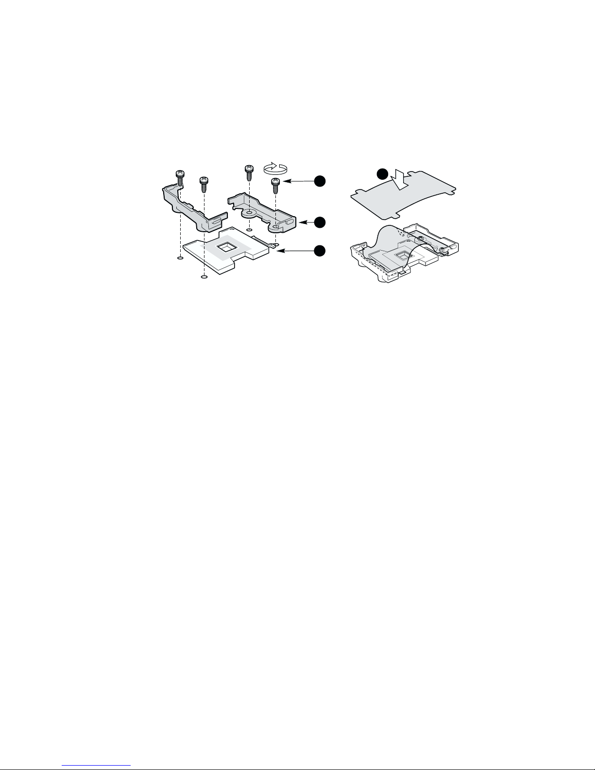
Replacing a Server Board
1. Before removing the cover to work inside the system, observe the safety guidelines on page 45.
2. Disconnect all cables from the rear I/O of the chassis.
3. Remove the cover from the chassis.
4. Remove the PCI riser cards.
5. Remove the fan module.
6. Unplug all cables connected to the server board.
7. Remove any processors and DIMMs that you wish to use with the new board. (See the
documentation that shipped with your server board.)
8. Remove the three mounting screws that secure the server board to the chassis (Figure 43).
9. Slide the board toward the front of the chassis until the I/O connectors are clear of the chassis
I/O openings and lift it from the chassis.
10. Ensure that the edge of the insulator sheet is below the studs in the rear chassis wall and that the
sheet is laying flat on the chassis floor.
11. Place the new server board on the chassis standoffs, being careful to position the board
I/O connectors in the rear chassis I/O openings.
12. Adjust board position so that the two mounting holes near the board edges rest securely on the
two corresponding shouldered standoffs.
13. Attach the board to the chassis using the three screws.
14. Install the processor(s), terminator, and memory cards that you wish to use with the new board.
Working Inside Your Server 61
Figure 43. Removing the Server Board
A
OM14119
Page 62

CAUTION
Carefully route cables in their original paths to minimize airflow blockage
and cooling problems.
15. Cable the new server board to the other system components.
16. Install the fan module.
17. Install the PCI riser cards.
18. Replace the chassis cover.
19. Connect any cables removed from the rear I/O of the chassis.
62 Intel SR2300 Chassis Subassembly Product Guide
Page 63

A Regulatory and Certification Information
WARNING
You must adhere to the assembly instructions in this guide to ensure and
maintain compliance with existing product certifications and approvals.
Use only the described, regulated components specified in this guide.
Use of other products / components will void the UL Listing and other
regulatory approvals of the product, and will most likely result in
noncompliance with product regulations in the region(s) in which the
product is sold.
Product Regulatory Compliance
The SR2300 chassis subassembly, when correctly integrated per this guide, complies with the
following safety and electromagnetic compatibility (EMC) regulations.
Product Safety Compliance
• UL 1950 - CSA 950 (US/Canada)
• EN 60 950 (European Union)
• IEC60 950 (International)
• CE – Low Voltage Directive (73/23/EEC) (European Union)
• EMKO-TSE (74-SEC) 207/94 (Nordics)
• GOST R 50377-92 (Russia)
• IRAM Type Certification (Argentina)
Product EMC Compliance
• FCC /ICES-003, Class A Emissions (USA/Canada) Verification
• CISPR 22, 3
• EN55022, Class A Emissions (CENELEC Europe)
• EN55024: 1998, Immunity (CENELEC Europe)
• EN61000-3-2, Harmonics (CENELEC Europe)
• EN61000-3-3, Voltage Flicker (CENELEC Europe)
• CE – EMC Directive 89/336/EEC (CENELEC Europe)
• VCCI, Class A Emissions (Japan)
• AS/NZS 3548 Class A Emissions (Australia / New Zealand)
• BSMI CNS13438 Class A Emissions (Taiwan)
• GOST R 29216-91, Class A Emissions (Russia)
• GOST R 50628-95, Immunity (Russia)
• RRL, MIC Notice No. 1997-41 (EMC) & 1997-42 (EMI) (Korea)
rd
Edition, Class A Emissions (International)
63
Page 64

Product Regulatory Compliance Markings
The SR2300 server chassis will be marked with the following regulatory markings.
cULus Listing Marks
German GS Mark
CE Mark
FCC Marking (Class A)
Canada EMC Marking (Class A)
Japan VCCI Marking (Class A)
BSMI Certification Number
Taiwan BSMI Marking (Class A)
Russia GOST R Marking
Korea RRL MIC Mark
64 Intel SR2300 Chassis Subassembly Product Guide
Page 65

Electromagnetic Compatibility Notices
FCC Verification Statement (USA)
Product Type: SR2300
This device complies with Part 15 of the FCC Rules. Operation is subject to the following two
conditions: (1) This device may not cause harmful interference, and (2) this device must accept any
interference received, including interference that may cause undesired operation.
Intel Corporation
5200 N.E. Elam Young Parkway
Hillsboro, OR 97124-6497
Phone: 1-800-628-8686
This equipment has been tested and found to comply with the limits for a Class A digital device,
pursuant to Part 15 of the FCC Rules. These limits are designed to provide reasonable protection
against harmful interference in a residential installation. This equipment generates, uses, and can
radiate radio frequency energy and, if not installed and used in accordance with the instructions,
may cause harmful interference to radio communications. However, there is no guarantee that
interference will not occur in a particular installation. If this equipment does cause harmful
interference to radio or television reception, which can be determined by turning the equipment off
and on, the user is encouraged to try to correct the interference by one or more of the following
measures:
• Reorient or relocate the receiving antenna.
• Increase the separation between the equipment and the receiver.
• Connect the equipment into an outlet on a circuit different from that to which the receiver is
connected.
• Consult the dealer or an experienced radio/TV technician for help.
Any changes or modifications not expressly approved by the grantee of this device could void the
user’s authority to operate the equipment. The customer is responsible for ensuring compliance of
the modified product.
Only peripherals (computer input/output devices, terminals, printers, etc.) that comply with FCC
Class A or B limits may be attached to this computer product. Operation with noncompliant
peripherals is likely to result in interference to radio and TV reception.
All cables used to connect to peripherals must be shielded and grounded. Operation with cables,
connected to peripherals that are not shielded and grounded may result in interference to radio and
TV reception.
Regulatory and Certification Information 65
Page 66

ICES-003 (Canada)
Cet appareil numérique respecte les limites bruits radioélectriques applicables aux appareils
numériques de Classe Aprescrites dans la norme sur le matériel brouilleur: “Appareils
Numériques”, NMB-003 édictée par le Ministre Canadien des Communications.
(English translation of the notice above.) This digital apparatus does not exceed the Class A limits
for radio noise emissions from digital apparatus set out in the interference-causing equipment
standard entitled “Digital Apparatus,” ICES-003 of the Canadian Department of Communications.
Europe (CE Declaration of Conformity)
This product has been tested in accordance too, and complies with the Low Voltage Directive
(73/23/EEC) and EMC Directive (89/336/EEC). The product has been marked with the CE Mark
to illustrate its compliance.
VCCI (Japan)
English translation of the notice above:
This is a Class A product based on the standard of the Voluntary Control Council for Interference
(VCCI) from Information Technology Equipment. If this is used near a radio or television receiver
in a domestic environment, it may cause radio interference. Install and use the equipment
according to the instruction manual.
66 Intel SR2300 Chassis Subassembly Product Guide
Page 67

BSMI (Taiwan)
The BSMI ID certification number 3902I901 and the following EMC warning are located on the
outside rear area of the product.
Korea – RRL Certification Information
The English translation for the above is as follows:
1. Type of Equipment (Model Name): SR2300
2. Certification No.: On RRL Certificate. Obtain certificate from Local Intel Representative
3. Name of Certification Recipient: Intel Corporation
4. Date of Manufacturer: Refer to date code on product
5. Manufacturer / Nation : Intel Corporation / Refer to Country of Origin Marked on Product
Regulated Specified Components
To maintain the UL listing and compliance to other regulatory certifications and/or declarations, the
following regulated components must be used, and conditions adhered to. Interchanging or use of
other component will void the UL Listing and other product certifications and approvals.
Updated product information for configurations can be found on Intel’s Server Builder Web-site at:
http://channel.intel.com/go/serverbuilder
If you do not have access to Intel’s web address please contact your local Intel representative.
• SR2300 chassis (base chassis is provided with power supply and fans)UL listed.
• Server boardyou must use an Intel Server Board – UL Recognized.
• Add-in boardsmust have a printed wiring board flammability rating of minimum UL94V-1.
Add-in boards containing external power connectors and/or lithium batteries must be UL
Recognized or UL Listed. Any add-in board containing modem telecommunication circuitry
must be UL Listed. In addition the modem must have the appropriate telecommunications,
safety and EMC approvals for the region in which it is sold.
• Peripheral storage devicesmust be UL Recognized or UL listed accessory and TUV or
VDE licensed. Maximum power rating of any one device is 19W. Total server configuration is
not to exceed maximum loading conditions of power supply.
When using a UL Recognized Peripheral Storage Device, the plastic bezel must be made of
a UL recognized plastic with flammability rating of UL94V-1.
Regulatory and Certification Information 67
Page 68

68 Intel SR2300 Chassis Subassembly Product Guide
Page 69

B Equipment Log and Worksheets
Equipment Log
Use the blank equipment log provided here to record information about your system. You will
need some of this information when you run the SSU.
Item
Chassis
Server Board
Processor Speed and
Cache
Video Display
Video Controller
Keyboard
Mouse
3.5-inch Drive
CD-ROM Drive
Hard Disk Drive 1
Hard Disk Drive 2
Hard Disk Drive 3
Hard Disk Drive 4
Hard Disk Drive 5
Hard Disk Drive 6
Manufacturer Name and
Model Number
Serial Number
Date Installed
continued
69
Page 70

Equipment Log (continued)
Item
Hard Disk Drive 7
DAT Tape Drive
Manufacturer Name and
Model Number
Serial Number
Date Installed
70 Intel SR2300 Chassis Subassembly Product Guide
Page 71

Current Usage
Calculating Power Usage
The total combined power consumption for your configuration must be less than 500W, with any
combination of loads not to exceed maximum current on any one channel as defined in Table 1.
The combined power consumption on 5 V and 3.3 V should not be more then 150W. Use the two
worksheets in this section to calculate the total used by your configuration. For current and voltage
requirements of add-in boards and peripherals, see your vendor documents.
Worksheet, Calculating DC Power Usage
1. List the current for each board and device in the appropriate voltage level column.
2. Add the current in each column, then go to the next worksheet.
Table 3. Power Usage Worksheet 1
Current (maximum) at voltage level:
Device +5 Vsb +3.3 V +5 V +12 V –12 V
Boards, processors, and
memory (get totals from your
board manual)
SCSI backplane and front panel 0.40
3.5-inch drive 0.30
CD-ROM drive 0.60
3.5-inch tape drive or other
peripheral
1st hot swap hard drive
2nd hot swap hard drive
3rd hot swap hard drive
4th hot swap hard drive
5th hot swap hard drive
6th hot swap hard drive
7th hot swap hard drive
Cooling fans (3 or 4)
60 mm, 1.2 A each on 12 V
Total Current
Maximum Ratings
(for comparison) 480W
500W3
Notes:
1 Maximum continuous total DC power output should not exceed 480W.
2 Maximum continuous combined load for +3.3V and +5V must not exceed 115W.
3 Maximum continuous combined load for +3.3V and +5V must not exceed 120W.
1,2
2A
2A
24A
20A
20A
20A
32A
36A
.5A
.5A
Equipment Log and Worksheets 71
Page 72

Worksheet, Total Combined Power Used by the System
1. From the previous worksheet, enter the total current for each column.
2. Multiply the voltage by the total current to get the total wattage for each voltage level.
3. Add the total wattage for each voltage level to arrive at a total combined power usage on the
power supply.
Table 4. Power Usage Worksheet 2
Voltage level and total current
(V X A = W)
(+5 Vsb) X (______ A) ________ W
(+3.3 V) X (______ A) ________ W
(+5 V) X (______ A) ________ W
(+12 V) X (______ A) ________ W
(–12 V) X (______ A) ________ W
Total Combined Wattage ________ W
CAUTION
Total Watts for each voltage level
Do not overload: As an overall current usage limitation on the power
supply, do not exceed a combined power output of 250W for all DC outputs.
72 Intel SR2300 Chassis Subassembly Product Guide
Page 73

C Safety Warnings
WARNING: English (US)
AVERTISSEMENT: Français
WARNUNG: Deutsch
AVVERTENZA: Italiano
ADVERTENCIAS: Español
73
Page 74

WARNING: English (US)
The power supply in this product contains no user-serviceable parts. There may be more
than one supply in this product. Refer servicing only to qualified personnel.
Do not attempt to modify or use the supplied AC power cord if it is not the exact type
required. A product with more than one power supply will have a separate AC power cord
for each supply.
The power but ton on the system does not turn off system AC power. To remove AC power
from the syste m, you must unplug each AC power cord from the wall outlet or power supply.
The power cord(s) is considered the disconnect device to the mains (AC) power. The socket
outlet that the system p lugs into shall be installed near the equipment and shall be easily
accessible.
SAFETY STEPS: Whenever you remove the chassis covers to access the inside of the
system, follow these steps:
1. Turn off all peripheral devices connected to the system.
2. Turn off the system by pressing the power button.
3. Unplug all AC power cords from the system or from wall outlets.
4. Label and disconnect all cables connected to I/O connectors or ports on the back of the
system.
5. Provide some electrostatic discharge (ESD) protection by wearing an antistatic wrist
strap attached to chassis ground of the system—any unpainted metal surface—when
handling components.
6. Do not operate the system with the chassis covers removed .
After you have completed the six SAFETY steps above, you can remove the system covers.
To do this:
1. Remove and save all screws from the covers.
2. Remove the covers.
continued
74 Intel SR2300 Chassis Subassembly Product Guide
Page 75

WARNING: English (continued)
For proper cooling and airflow, always reinstall the chassis covers before turning on the
system. Operating the system without the covers in place can damage syste m parts. To
install the covers:
1. Check first to make sure you have not left loose tools or parts inside the system.
2. Check that cables, add-in boards, and other components are properly installed.
3. Attach the covers to the chassis with the screws removed earlier, and tighten them
firmly.
4. Connect all external cables and the AC power cord(s) to the system.
A microprocessor and heat sink may be hot if the system has been running. Also, there may
be sharp pins and edges on some board and chassis parts. Contact should be made with
care. Consider wearing protective gloves.
Danger of explosion if the battery is incorrectly replaced. Replace only with the same or
equivalent type recommended by the equipment manufacturer. Dispose of used batteries
according to manufacturer’s instructions.
The system is designed to operate in a typical office environment. Choose a site that is:
• Clean and free of airborne particles (other than normal room dust).
• Well-ventilated and away from sources of heat including direct sunlight.
• Away from sources of vibration or physical shock.
• Isolated from strong electromagnetic fields produced by electrical devices.
• In regions that are susceptible to electrical storms, we recommend you plug your system
into a surge suppresser and disconnect telecommunication lines to your modem during an
electrical storm.
• Provided with a properly grounded wall outlet.
• Provided with sufficient space to access the power supply cord(s), because they serve as
the product’s main power disconnect.
Safety Warnings 75
Page 76

AVERTISSEMENT: Français
Le bloc d'alimentation de ce produit ne contient aucune pièce pouvant être réparée par
l'utilisateur. Ce produit peut contenir plus d'un bloc d'alimentation. Veuillez contacter un
technicien qualifié en cas de problème.
Ne pas essayer d'utiliser ni modifier le câble d'alimentation CA fourni, s'il ne correspond pas
exactement au type requis. Le nombre de câbles d'alimentation CA fournis correspond au
nombre de blocs d'alimentation du produit.
Notez que le commutateur CC de mise sous tension /hors tension du panneau avant n'éteint
pas l'alime ntation CA du système. Pour mettre le système hors tension, vous devez
débrancher chaque câble d'alimentation de sa prise.
CONSIGNES DE SÉCURITÉ -Lorsque vous ouvrez le boîtier pour accéder à l’intérieur du
système, suivez les consignes suivantes:
1. Mettez hors tension tous les périphériques connectés au système.
2. Mettez le système hors tension en mettant l’interrupteur général en position OFF
(bouton-poussoir).
3. Débranchez tous les cordons d’alimentation c.a. du système et des prises murales.
4. Identifiez et débranchez tous les câbles reliés aux connecteurs d’E-S ou aux accès
derrière le système.
5. Pour prévenir les décharges électrostatiques lorsque vous touchez aux composants,
portez une bande antistatique pour poignet et reliez-la à la masse du système (toute
surface métallique non peinte du boîtier).
6. Ne faites pas fonctionner le système tandis que le boîtier est ouvert.
Une fois TOUTES les étapes précédentes accomplies, vous pouvez retirer les panneaux du
système. Procédez comme suit:
1. Retirez toutes les vis des panneaux et mettez-les dans un endroit sûr.
2. Retirez les panneaux.
suite
76 Intel SR2300 Chassis Subassembly Product Guide
Page 77

AVERTISSEMENT: Français (suite)
Afin de permettre le refroidissement et l’aération du système, réinstallez toujours les
panneaux du boîtier avant de mettre le système sous tension. Le fonctionnement du
système en l’absence des panneaux risque d’endommager ses pièces. Pour installer le s
panneaux, procédez comme suit:
1. Assurez-vous de ne pas avoir oublié d’outils ou de pièces démontées dans le système.
2. Assurez-vous que les câbles, les cartes d’extension et les autres composants sont bien
installés.
3. Revissez solidement les panneaux du boîtier avec les vis retirées plus tôt.
4. Rebranchez tous les cordons d’alimentation c. a. et câbles extern es au système.
Le microprocesseur et le dissipateur de chaleur peuvent être chauds si le système a été
sous tension. Faites également attention aux broches aiguës des cartes et aux bords
tranchants du capot. Nous vous recommandons l'usage de gants de protection.
Danger d'explosion si la batterie n'est pas remontée correctement. Remplacer uniquement
avec une batterie du même type ou d'un type équivalent recommandé par le fabricant.
Disposez des piles usées selon les instructions du fabricant.
Le système a été co nçu pour fonctionner dans un cadre de travail normal. L'emplacement
choisi doit être:
• Propre et dépourvu de poussière en suspension (sauf la poussière normale).
• Bien aéré et loin des sources de chaleur, y compris du solei l direct.
• A l'abri des chocs et des sources de vibrations.
• Isolé de forts champs électromagnétiques générés par des appareils électriques.
• Dans les régions sujettes aux orages magnétiques il est recommandé de brancher votre
système à un supresseur de surtension, et de débrancher toutes les lignes de
télécommunications de votre modem durant un orage.
• Muni d'une prise murale correctement mise à la terre.
• Suffisamment spacieux pour vous permettre d'accéder aux câbles d'alimentation (ceux-ci
étant le seul moyen de mettre le système hors tension).
Safety Warnings 77
Page 78

WARNUNG: Deutsch
Benutzer können am Netzgerät dieses Produkts keine Reparaturen vornehmen. Das
Produkt enthält möglicherweise mehrere Netzgeräte. Wartungsarbeiten müssen von
qualifizierten Technikern ausgeführt werden.
Versuchen Sie nicht, das mitgelieferte Netzkabel zu ändern oder zu verwenden, wenn es
sich nicht genau um den erforderlichen Typ handelt. Ein Produkt mit mehreren Netzgeräten
hat für jedes Netzgerät ein eigenes Netzkabel.
Der Wechselstrom des Systems wird durch den Ein-/Aus-Schalter für Gleichstrom nicht
ausgeschaltet. Ziehen Sie jedes Wechselstrom-Netzkabel aus der Steckdose bzw. dem
Netzgerät, um den Stromanschluß des Systems zu unterbrechen.
SICHERHEISMASSNAHMEN: Immer wenn Sie die Gehäuseabdeckung abnehmen um an
das Systeminnere zu gelangen, sollten Sie folgende Schritte beachten:
1. Schalten Sie alle an Ihr System angeschlossenen Peripheriegeräte aus.
2. Schalten Sie das System mit dem Hauptschalter aus.
3. Ziehen Sie den Stromanschlußstecker Ihres Systems aus der Steckdose.
4. Auf der Rückseite des Systems beschriften und ziehen Sie alle A nschlußkabel von den
I/O Anschlüssen oder Ports ab.
5. Tragen Sie ein geerdetes Antistatik Gelenkband, um elektrostatische Ladungen (ESD)
über blanke Metallstellen bei der Handhabung der Komponenten zu vermeiden.
6. Schalten Sie das System niemals ohne ordnungsgemäß montiertes Gehäuse ein.
Nachdem Sie die oben erwähnten ersten sechs SICHERHEITSSCHRITTE durchgeführt
haben, können Sie die Abdeckung abnehmen, indem Sie:
1. Entfernen Sie alle Schrauben der Gehäuseabdeckung.
2. Nehmen Sie die Abdeckung ab.
Fortsetzung
78 Intel SR2300 Chassis Subassembly Product Guide
Page 79

WARNUNG: Deutsch (Fortsetzung)
Zur ordnungsgemäßen Kühlung und Lüftung muß die Gehäuseabdeckung immer wieder vor
dem Einschalten installiert werden. Ein Betrieb des Systems ohne angebrachte Abdeckung
kann Ihrem System oder Teile darin beschädigen. Um die Abdeckung wieder anzubringen:
1. Vergewissern Sie sich, daß Sie keine Werkzeuge oder Teile im Innern des Systems
zurückgelassen haben.
2. Überprüfen Sie alle Kabel, Zusatzkarten und andere Komponenten auf
ordnungsgemäßen Sitz und Installation.
3. Bringen Sie die Abdeckungen wieder am Gehäuse an, indem Sie die zuvor gelösten
Schrauben wieder anbringen. Ziehen Sie diese gut an.
4. Schließen Sie alle externen Kabel und den AC Stromanschlußstecker Ihres Systems
wieder an.
Der Mikroprozessor und der Kühler sind möglicherweise erhitzt, wenn das System in Betrieb
ist. Außerdem können einige Platinen und Gehäuseteile scharfe Spitzen und Kanten
aufweisen. Arbeiten an Platinen und Gehäuse sollten vorsichtig ausgeführt werden. Sie
sollten Schutzhandschuhe tragen.
Bei falschem Einsetzen einer neuen Batterie besteht Explosionsgefahr. Die Batterie darf nur
durch denselben oder einen entsprechenden, vom Hersteller empfohlenen Batterietyp
ersetzt werden. Entsorgen Sie verbrauchte Batterien den Anweisungen des Herstellers
entsprechend.
Das System wurde für den Betrieb in einer normalen Büroumgebung entwickelt. Der
Standort sollte:
• sauber und staubfrei sein (Hausstaub ausgenommen);
• gut gelüftet und keinen Heizquellen ausgesetzt sein (einschließlich direkter
Sonneneinstrahlung);
• keinen Erschütterungen ausgesetzt sein;
• keine starken, von elektrischen Geräten erzeugten elektromagnetischen Felder
aufweisen;
• in Regionen, in denen elektrische Stürme auftreten, mit einem Überspannungsschutzgerät
verbunden sein; während eines elektrischen Sturms sollte keine Verbindung der
Telekommunikationsleitungen mit dem Modem bestehen;
• mit einer geerdeten Wechselstromsteckdose ausgerüstet sein;
• über ausreichend Platz verfügen, um Zugang zu den Netzkabeln zu gewährleisten, da der
Stromanschluß des Produkts hauptsächlich über die Kabel unterbrochen wird.
Safety Warnings 79
Page 80

AVVERTENZA: Italiano
Rivolgersi ad un tecnico specializzato per la riparazione dei componenti dell’alime ntaz ione di
questo prodotto. È possibile che il prodotto disponga di più fonti di alimentazione.
Non modificare o utilizzare il cavo di alimentazione in c.a. fornito dal produttore, se non
corrisponde esattamente al tipo richiesto. Ad ogni fonte di alimentazione corrisponde un
cavo di alimentazione in c.a. separato.
L’interruttore attivato/disattivato nel pannello anteriore non interrompe l’alimentazione in c.a.
del sistema. Per interromperla, è necessario scollegare tutti i cavi di alimentazione in c.a.
dalle prese a muro o dall’alimentazione di corrente.
PASSI DI SICUREZZA: Qualora si rimuovano le coperture del telaio per accedere
all’interno del sistema, seguire i seguenti passi:
1. Spegnere tutti i dispositivi periferici collegati al sistema.
2. Spegnere il sistema, usando il pulsante spento/acceso dell’interruttore del sistema.
3. Togliere tutte le spine dei cavi del sistema dalle prese elettriche.
4. Identificare e sconnettere tutti i cavi attaccati ai collegamenti I/O od alle prese installate
sul retro del sistema.
5. Qualora si tocchino i componenti, proteggersi dallo scarico elettrostatico (SES),
portando un cinghia anti-statica da polso che è attaccata alla presa a terra del telaio del
sistema – qualsiasi superficie non dipinta – .
6. Non far operare il sistema quando il telaio è senza le coperture.
Dopo aver seguito i sei passi di SICUREZZA sopracitati, togliere le coperture del telaio del
sistema come seque:
1. Togliere e mettere in un posto sicuro tutte le viti delle coperture.
2. Togliere le coperture.
continua
80 Intel SR2300 Chassis Subassembly Product Guide
Page 81

AVVERTENZA: Italiano (continua)
Per il giusto flusso dell’aria e raffreddamento del sistema, rimettere sempre le coperture del
telaio prima di riaccendere il sistema. Operare il sistema senza le coperture al loro proprio
posto potrebbe danneggiare i componenti del sistema. Per rimettere le coperture del telaio:
1. Controllare prima che non si siano lasciati degli attrezzi o dei componenti dentro il
sistema.
2. Controllare che i cavi, dei supporti aggiuntivi ed altri componenti siano stati installati
appropriatamente.
3. Attaccare le coperture al telaio con le viti tolte in precedenza e avvitarle strettamente.
4. Ricollegare tutti i cavi esterni e le prolunghe AC del sistema.
Se il sistema è stato a lungo in funzione, il microprocessore e il dissipatore di calore
potrebbero essere surriscaldati. Fare attenzione alla presenza di piedini appuntiti e parti
taglienti sulle schede e sul telaio. È consigliabile l'uso di guanti di protezione.
Esiste il pericolo di un esplosione se la pila non viene sostituita in modo corretto. Utilizzare
solo pile uguali o di tipo equivalente a quelle consigliate dal produttore. Per disfarsi delle pile
usate, seguire le istruzioni del produttore.
Il sistema è progettato per funzionare in un ambiente di lavoro tipo. Scegliere una
postazione che sia:
• Pulita e libera da particelle in sospensione (a parte la normale polvere presente
nell'ambiente).
• Ben ventilata e lontana da fonti di calore, compresa la luce solare diretta.
• Al riparo da urti e lontana da fonti di vibrazione.
• Isolata dai forti campi magnetici prodotti da dispositivi elettrici.
• In aree soggette a temporali, è consigliabile collegare il sistema ad un limitatore di
corrente. In caso di temporali, scollegare le linee di comunicazione dal modem.
• Dotata di una presa a muro correttamente installata.
• Dotata di spazio sufficiente ad accedere ai cavi di alimentazione, i quali rappresentano il
mezzo principale di scollegamento del sistema.
Safety Warnings 81
Page 82

ADVERTENCIAS: Español
El usuario debe abstenerse de manipular los componentes de la fuente de alimentación de
este producto, cuya reparación debe dejarse exclusivamente en manos de personal técnico
especializado. Puede que este producto disponga de más de una fuente de alimentación.
No intente modificar ni usar el cable de alimentación de corriente alterna, si no corresponde
exactamente con el tipo requerido.
El número de cables suministrados se corresponden con el número de fuentes de
alimentación de corriente alterna que tenga el producto.
Nótese que el interruptor activado/desactivado en el panel frontal no desconecta la corriente
alterna del sistema. Para desconectarla, deberá desenchufar todos los cables de corriente
alterna de la pared o desconectar la fuente de alimentación.
INSTRUCCIONES DE SEGURIDAD: Cuando extraiga la tapa del chasis para acceder al
interior del sistema, siga las siguientes instrucciones:
1. Apague todos los dispositivos periféricos conectados al sistema.
2. Apague el sistema presionando el interruptor encendido/apagado.
3. Desconecte todos los cables de alimentación CA del sistema o de las tomas de
corriente alterna.
4. Identifique y desconecte todos los cables enchufados a los conectores E/S o a los
puertos situados en la parte posterior del sistema.
5. Cuando manipule los componentes, es importante protegerse contra la descarga
electrostática (ESD). Puede hacerlo si utiliza una muñequera antiestática sujetada a la
toma de tierra del chasis — o a cualquier tipo de superficie de metal sin pintar.
6. No ponga en marcha el sistema si se han extraído las tapas del chasis.
Después de completar las seis instrucciones de SEGURIDAD mencionadas, ya puede
extraer las tapas del sistema. Para ello:
1. Extraiga y guarde todos los tornillos de las tapas.
2. Extraiga las tapas.
continúa
82 Intel SR2300 Chassis Subassembly Product Guide
Page 83

ADVERTENCIAS: Español (continúa)
Para obtener un enfriamiento y un flujo de aire adecuados, reinstale siempre las tapas del
chasis antes de poner en marcha el sistema. Si pone en funcionamiento el sistema sin las
tapas bien colocadas puede dañar los componentes del sistema. Para instalar las tapas:
1. Asegúrese primero de no haber dejado herramientas o componentes sueltos dentro del
sistema.
2. Compruebe que los cables, las placas adicionales y otros componentes se hayan
instalado correctamente.
3. Incorpore las tapas al chasis mediante los tornillos extraídos anteriormente, tensándolos
firmemente.
4. Conecte todos los cables externos y los cables de alimentación CA al sistema.
Si el sistema ha estado en funcionamiento, el microprocesador y el disipador de calor
pueden estar aún calientes. También conviene tener en cuenta que en el chasis o en el
tablero puede haber piezas cortantes o punzantes. Por ello, se recomienda precaución y el
uso de guantes protectores.
Existe peligro de explosión si la pila no se cambia de forma adecuada. Utilice solamente
pilas iguales o del mismo tipo que las recomendadas por el fabricante del equipo. Para
deshacerse de las pilas usadas, siga igualmente las instrucciones del fabricante.
El sistema está diseñado para funcionar en un entorno de trabajo normal. Escoja un lugar:
• Limpio y libre de partículas en suspensión (salvo el polvo normal).
• Bien ventilado y alejado de fuentes de calor, incluida la luz solar directa.
• Alejado de fuentes de vibración.
• Aislado de campos electromagnéticos fuertes producidos por dispositivos eléctricos.
• En regiones con frecuentes tormentas eléctricas, se recomienda conectar su sistema a un
eliminador de sobrevoltage y desconectar el módem de las líneas de telecomunicación
durante las tormentas.
• Provisto de una toma de tierra correctamente instalada.
• Provisto de espacio suficiente como para acceder a los cables de alimentación, ya que
éstos hacen de medio principal de desconexión del sistem a.
Safety Warnings 83
Page 84

84 Intel SR2300 Chassis Subassembly Product Guide
Page 85

D Warranty
Limited Warranty for Intel® Chassis Subassembly
Products
Intel warrants that the Products (defined herein as the Intel® chassis subassembly and all of its
various components and software delivered with or as part of the Products) to be delivered
hereunder, if properly used and installed, will be free from defects in material and workmanship
and will substantially conform to Intel’s publicly available specifications for a period of three
(3) years after the date the Product was purchased from an Intel authorized distributor. Software of
any kind delivered with or as part of products is expressly provided “as is” unless specifically
provided for otherwise in any software license accompanying the software.
If any Product furnished by Intel that is the subject of this Limited Warranty fails during the
warranty period for reasons covered by this Limited Warranty, Intel, at its option, will:
• REPAIR the Product by means of hardware and/or software; OR
• REPLACE the Product with another Product; OR
• REFUND the then-current value of the Product if Intel is unable to repair or replace
the Product.
If such Product is defective, Intel will pay transportation charges for the return of Product to buyer
within the USA. For all other locations, the warranty excludes all costs of shipping, customs
clearance, and other related charges. Intel will have a reasonable time to make repairs or to replace
Product or to refund the then-current value of the Product.
In no event will Intel be liable for any other costs associated with the replacement or repair of
Product, including labor, installation or other costs incurred by buyer and in particular, any costs
relating to the removal or replacement of any product soldered or otherwise permanently affixed to
any printed circuit board.
This Limited Warranty, and any implied warranties that may exist under state law, apply only to the
original purchaser of the Product.
Extent of Limited Warranty
Intel does not warrant that Products to be delivered hereunder, whether delivered stand-alone or
integrated with other Products, including without limitation semiconductor components, will be
free from design defects or errors known as “errata”. Current characterized errata are available
upon request.
This Limited Warranty does not cover damages due to external causes, including accident,
problems with electrical power, usage not in accordance with product instructions, misuse, neglect,
alteration, repair, improper installation, or improper testing.
85
Page 86

Warranty Limitations and Exclusions
These warranties replace all other warranties, expressed or implied including, but not limited to, the
implied warranties of merchantability and fitness for a particular purpose. Intel makes no
expressed warranties beyond those stated here. Intel disclaims all other warranties, expressed or
implied including, without limitation, implied warranties of merchantability and fitness for a
particular purpose. Some jurisdictions do not allow the exclusion of implied warranties, so this
limitation may not apply.
All expressed and implied warranties are limited in duration to the limited warranty period. No
warranties apply after that period. Some jurisdictions do not allow limitations on how long an
implied warranty lasts, so this limitation may not apply to you.
Limitations of Liability
Intel’s responsibility under this, or any other warranty, implied or expressed, is limited to repair,
replacement or refund, as set forth above. These remedies are the sole and exclusive remedies for
any breach of warranty. Intel is not responsible for direct, special, incidental, or consequential
damages resulting from any breach of warranty under another legal theory including, but not
limited to, lost profits, downtime, goodwill, damage to or replacement of equipment and property,
and any costs of recovering, reprogramming, or reproducing any program or data stored in or used
with a system containing this product. Some jurisdictions do not allow the exclusion or limitation
of incidental or consequential damages, so the above limitations or exclusions may not
apply to you.
This limited warranty gives you specific legal rights, and you may also have other rights that vary
from jurisdiction to jurisdiction.
Any and all disputes arising under or related to this Limited Warranty shall be adjudicated in the
following forums and governed by the following laws: for the United States of America, Canada,
North America and South America, the forum shall be Santa Clara, California, USA and the
applicable law shall be that of the State of California, USA; for the Asia Pacific region, the forum
shall be Singapore and the applicable law shall be that of Singapore; for Europe and the rest of the
world, the forum shall be London and the applicable law shall be that of the United Kingdom.
In the event of any conflict between the English language version and any other translated
version(s) of this Limited Warranty, the English language version shall control.
86 Intel SR2300 Chassis Subassembly Product Guide
Page 87

How to Obtain Warranty Service
To obtain warranty service for this Product, you may contact Intel or your authorized distributor.
North America & Latin AmericaTo obtain warranty repair for the product, please go to this
website to obtain instructions:
http://support.intel.com/support/motherboards/draform.htm
In Europe and in AsiaContact your original authorized distributor for warranty service.
Any replacement Product is warranted under this written warranty and is subject to the same
limitations and exclusions for the remainder of the original warranty period.
Telephone Support
If you can’t find the information you need on Intel’s World Wide Web site (http://www.intel.com),
call your local distributor or an Intel Customer Support representative.
Country
United States &
Canada
UK
France
Germany
Italy
Spain
Finland
Denmark
Norway
Sweden
Holland
Asia-Pacific
Australia
Hong Kong
Korea
Philippines
PRC
Singapore
Taiwan
Malaysia
New Zealand
Indonesia
Thailand
Vietnam
India
Pakistan
Customer Support
Telephone Number
1-800-404-2284 7:00 - 17:00 PST Credit card calls
0870 6072439
01 41 918529
069 9509 6099
02 696 33276
91 377 8166
9 693 79297
38 487077
23 1620 50
08 445 1251
020 487 4562
+1-800-649-931
+852-2-844-4456
+822-767-2595
1800-1-651-0117
(800)8201100
(65)2131311
2 27189915
1800-801390
0800-444365
803-65-7249
800-6310003
IDD call +63(2)6368416
(0006517) 830-3634
Manual toll free. From
India, you need an
IDD-equipped phone.
IDD call +63(2)6368415
Hours
(Monday-Friday)
UK time
8:00 - 17:00 (M, Th, F)
8:00 - 16:00 (Tu - W)
Singapore local time
Oct-April: 6:00 - 16:00
April-Oct: 5:00 - 16:00
Billing
$25.00/incident
Credit Card Calls $25.00/incident
Levied in local currency at the
applicable credit card exchange rate
plus applicable VAT
Warranty 87
Page 88

Returning a Defective Product
Before returning any product, call your authorized dealer/distribution authority.
88 Intel SR2300 Chassis Subassembly Product Guide
 Loading...