

Page 1

Intel® Entry Server Board SE7221BA1-E
User Guide
A Guide for Technically Qualified Assemblers of Intel® Identified
Subassemblies/Products
Order Number: C92730-002
Page 2

Disclaimer
Disclaimer
Information in this document is provided in connection with Intel
otherwise, to any intellectual property rights is granted by this document. Except as provided in Intel’s Terms and Conditions
of Sale for such products, Intel assumes no liability whatsoever, and Intel disclaims any express or implied warranty, relating
to sale and/or use of Intel products including liability or warranties relating to fitness for a particular purpose, merchantability,
or infringement of any patent, copyright or other intellectual property right. Intel products are not designed, intended or
authorized for use in any medical, life saving, or life sustaining applications or for any other application in which the failure of
the Intel product could create a situation where personal injury or death may occur. Intel may make changes to
specifications and product descriptions at any time, without notice.
Intel server boards contain a number of high-density VLSI and power delivery components that need adequate airflow for
cooling. Intel’s own chassis are designed and tested to meet the intended thermal requirements of these components when
the fully integrated system is used together. It is the responsibility of the system integrator that chooses not to use Intel
developed server building blocks to consult vendor datasheets and operating parameters to determine the amount of airflow
required for their specific application and environmental conditions. Intel Corporation can not be held responsible if
components fail or the server board does not operate correctly when used outside any of their published operating or nonoperating limits.
Intel, Intel Pentium, and Intel Xeon are trademarks or registered trademarks of Intel Corporation or its subsidiaries in the
United States and other countries.
®
products. No license, express or implied, by estoppel or
* Other names and brands may be claimed as the property of others.
Copyright © 2004, Intel Corporation. All Rights Reserved
ii Intel® Entry Server Board SE7221BA1-E User Guide
Page 3

Preface
Preface
About this Manual
Thank you for purchasing and using the Intel® Entry Server Board SE7221BA1-E.
This manual is written for system technicians who are responsible for troubleshooting, upgrading,
and repairing this server board. This document provides a brief overview of the features of the
board/chassis, a list of accessories or other components you may need, troubleshooting information,
and instructions on how to add and replace components on the Intel® Entry Server Board
SE7221BA1-E. For the latest version of this manual, refer to
http://support.Intel.com/support/motherboards/server/SE7221BA1-E/.
Manual Organization
Chapter 1 provides a brief overview of the Intel® Entry Server Board SE7221BA1-E. In this
chapter, you will find a list of the server board features, photos of the product, and product
diagrams to help you identify components and their locations.
Chapter 2 provides instructions on adding and replacing components. Use this chapter for step-bystep instructions and diagrams for installing or replacing components such as the memory,
processor, and the battery, among other components.
Chapter 3 provides instructions on using the utilities that are shipped with the board or that may be
required to update the system. This includes how to perform a BIOS update, and how to reset the
password or CMOS. Information about the specific BIOS settings and screens is available in the
Intel® Entry Server Board Technical Product Specification. See “Additional Information and
Software” for a link.
Chapter 4 provides troubleshooting information. In this chapter, you will find BIOS error messages
and POST code messages. You will also find suggestions for performing troubleshooting activities
to identify the source of a problem.
Product Accessories
You may need or want to purchase one or more of the following accessory items for your server:
Processor, memory DIMMs, hard drive, floppy drive, CDROM or DVDROM drive, RAID
controller, operating system.
Intel® Entry Server Board SE7221BA1-E User Guide iii
Page 4
Additional Information and Software
If you need more information about this product or information about the accessories that can be
used with this server board, use the following resources. These files are available at:
http://support.Intel.com/support/motherboards/server/SE7221BA1-E/.
If a link is not listed below, type the document or software name in the search field at the left side
of the screen and select the option to search “This Product.”
For this information or software Use this Document or Software
For in-depth technical information about
this product, including BIOS settings and
chipset information
If you just received this product and need
to install it
For virtual system tours and interactive
repair information
Accessories or other Intel® server
products
Hardware (peripheral boards, adapter
cards) and operating systems that have
been tested with this product
Chassis that have been tested with this
product
Processors that have been tested with
this product
DIMMs that have been tested with this
product
To make sure your system falls within the
allowed power budget
For software to manage your Intel®
server
For drivers Driver (for an extensive list of drivers available)
For firmware and BIOS updates Firmware Update
For diagnostics test software Diagnostics
Intel® Entry Server Board SE7221BA1-E Technical Product Specification
http://support.Intel.com/support/motherboards/server/SE7221BA1-E/sb/CS-
020016.htm
Intel® Entry Server Board SE7221BA1-E Quick Start User’s Guide in the product
box or at:
http://support.Intel.com/support/motherboards/server/SE7221BA1-E/sb/CS-
020024.htm
A link to the Intel® SMaRT Tool is available under “Other Resources” at the right
side of the screen at:
http://support.Intel.com/support/motherboards/server/SE7221BA1-E/
Spares and Configuration Guide
http://support.Intel.com/support/motherboards/server/SE7221BA1-E/sb/CS-
020022.htm
Tested Hardware and Operating System List
http://support.Intel.com/support/motherboards/server/SE7221BA1-E/sb/CS-
020021.htm
Reference Chassis List
http://support.Intel.com/support/motherboards/server/SE7221BA1-E/sb/CS-
020029.htm
Supported Processors
http://support.Intel.com/support/motherboards/server/SE7221BA1-E/sb/CS-
020019.htm
Supported Memory
http://support.Intel.com/support/motherboards/server/SE7221BA1-E/sb/CS-
020020.htm
Power Budget
Intel® Server Management
Operating System Driver (for operating system drivers)
http://downloadfinder.intel.com/scripts-df/Product_Filter.asp?ProductID=1959
http://downloadfinder.intel.com/scripts-df/Product_Filter.asp?ProductID=1959
ttp://downloadfinder.intel.com/scripts-df/Product_Filter.asp?ProductID=1959
Server Board Features
iv Intel® Entry Server Board SE7221BA1-E User Guide
Page 5

Preface
Safety Information
WARNING
Before working with your server product, whether you are using this guide or any other
resource as a reference, pay close attention to the safety instructions. You must adhere to the
assembly instructions in this guide to ensure and maintain compliance with existing product
certifications and approvals. Use only the described, regulated components specified in this
guide. Use of other products / components will void the UL listing and other regulatory
approvals of the product and will most likely result in noncompliance with product
regulations in the region(s) in which the product is sold.
Warnings
System power on/off: The power button DOES NOT turn off the system
AC power. To remove power from system, you must unplug the AC power
cord from the wall outlet. Make sure the AC power cord is unplugged before
you open the chassis, add, or remove any components.
Hazardous conditions, devices and cables: Hazardous electrical
conditions may be present on power, telephone, and communication cables.
Turn off the server and disconnect the power cord, telecommunications
systems, networks, and modems attached to the server before opening it.
Otherwise, personal injury or equipment damage can result.
Electrostatic discharge (ESD) and ESD protection: ESD can
damage disk drives, boards, and other parts. We recommend that you
perform all procedures in this chapter only at an ESD workstation. If one is
not available, provide some ESD protection by wearing an antistatic wrist
strap attached to chassis ground⎯any unpainted metal surface⎯on your
server when handling parts.
ESD and handling boards: Always handle boards carefully. They can
be extremely sensitive to ESD. Hold boards only by their edges. After
removing a board from its protective wrapper or from the server, place the
board component side up on a grounded, static free surface. Use a
conductive foam pad if available but not the board wrapper. Do not slide
board over any surface.
Installing or removing jumpers: A jumper is a small plastic encased
conductor that slips over two jumper pins. Some jumpers have a small tab on
top that you can grip with your fingertips or with a pair of fine needle nosed
pliers. If your jumpers do not have such a tab, take care when using needle
nosed pliers to remove or install a jumper; grip the narrow sides of the
jumper with the pliers, never the wide sides. Gripping the wide sides can
damage the contacts inside the jumper, causing intermittent problems with
the function controlled by that jumper. Take care to grip with, but not
squeeze, the pliers or other tool you use to remove a jumper, or you may
bend or break the pins on the board.
Intel® Entry Server Board SE7221BA1-E User Guide v
Page 6
Server Board Features
Safety Cautions
Read all caution and safety statements in this document before performing any of the instructions.
http://support.Intel.com/support/motherboards/server/sb/cs-010770.htm.
SAFETY STEPS: Whenever you remove the chassis covers to access the inside of the
system, follow these steps:
al devices connected to the system.
wall outlets.
orts on the back of
1. Turn off all peripher
2. Turn off the system by pressing the power button.
3. Unplug all AC power cords from the system or from
4. Label and disconnect all cables connected to I/O connectors or p
the system.
5. electrostatic discharge (ESD) protection by wearing an antistatic wrist
Provide some
strap attached to chassis ground of the system—any unpainted metal surface—
when handling components.
6. th the chassis covers removed.
Do not operate the system wi
A m p ning. Also, there may icro rocessor and heat sink may be hot if the system has been run
be sharp pins and edges on some board and chassis parts. Contact should be made with
care. Consider wearing protective gloves.
t See also Intel® Server Boards and Server Chassis Safety Information on the Resource CD and/or a
Wichtige Sicherheitshinweise
Lesen Sie zunächst sämtliche Warn- und Sicherheitshinweise in diesem Dokument, bevor Sie eine
der Anweisungen ausführen. Beachten Sie hierzu auch die Sicherheitshinweise zu Intel®Serverplatinen und -Servergehäusen auf der Ressourcen-CD oder unter
http://support.Intel.com/support/motherboards/server/sb/cs-010770.htm.
SICHERHEISMASSNAHMEN: Immer wenn Sie die Gehäuseabdeckung abnehmen um an
das Systeminnere zu gelangen, sollten Sie folgende Schritte beachten:
räte aus.
1. Schalten Sie alle an Ihr System angeschlossenen Peripheriege
2. Schalten Sie das System mit dem Hauptschalter aus.
3. Ziehen Sie den Stromanschlußstecker Ihres Systems a
4. Auf der Rückseite des Systems beschriften und ziehen Sie alle Anschlußkabel v
den I/O Anschlüssen oder Ports ab.
5. elenkband, um elektrostatische Ladungen
Tragen Sie ein geerdetes Antistatik G
(ESD) über blanke Metallstellen bei der Handhabung der Komponenten zu
vermeiden.
6. das System niemals ohne ordnungsgemäß montiertes Gehäuse ein.
Schalten Sie
Der r Mik oprozessor und der Kühler sind möglicherweise erhitzt, wenn das System in Betrieb
ist. Außerdem können einige Platinen und Gehäuseteile scharfe Spitzen und Kanten
aufweisen. Arbeiten an Platinen und Gehäuse sollten vorsichtig ausgeführt werden. Sie
sollten Schutzhandschuhe tragen.
us der Steckdose.
on
vi Intel® Entry Server Board SE7221BA1-E User Guide
Page 7
Preface
重要安全指导
在执行任何指令之前,请阅读本文档中的所有注意事项及安全声明。参见 Resource
CD(资源光盘) 和/或
上的
Intel® Server Boards and Server Chassis Safety Information
http://support.Intel.com/support/motherboards/server/sb/cs-010770.htm
(《Intel®
服务器主板与服务器机箱安全信息》)。
Consignes de sécurité
Lisez attention toutes les consignes de sécurité et les mises en garde indiquées dans ce document
avant de suivre toute instruction. Consultez Intel® Server Boards and Server Chassis Safety
Information sur le CD Resource CD ou bien rendez-vous sur le site
http://support.Intel.com/support/motherboards/server/sb/cs-010770.htm.
CONSIGNES DE SÉCURITÉ -Lorsque vous ouvrez le boîtier pour accéder à l’intérieur du
système, suivez les consignes suivantes:
1. Mettez hors tension tous les périphériques connectés au système.
2. Mettez le système hors tension en mettant l’interrupteur général en position OFF
(bouton-poussoir).
3. Débranchez tous les cordons d’alimentation c.a. du système et des prises murales.
4. Identifiez et débranchez tous les câbles reliés aux connecteurs d’E-S ou aux accès
derrière le système.
5. Pour prévenir les décharges électrostatiques lorsque vous touchez aux
composants, portez une bande antistatique pour poignet et reliez-la à la masse du
système (toute surface métallique non peinte du boîtier).
6. Ne faites pas fonctionner le système tandis que le boîtier est ouvert.
Le microprocesseur et le dissipateur de chaleur peuvent être chauds si le système a été
sous tension. Faites également attention aux broches aiguës des cartes et aux bords
tranchants du capot. Nous vous recommandons l'usage de gants de protection.
Instrucciones de seguridad importantes
Lea todas las declaraciones de seguridad y precaución de este documento antes de realizar
cualquiera de las instrucciones. Vea Intel® Server Boards and Server Chassis Safety Information
en el CD Resource y/o en
Intel® Entry Server Board SE7221BA1-E User Guide vii
http://support.Intel.com/support/motherboards/server/sb/cs-010770.htm.
INSTRUCCIONES DE SEGURIDAD: Cuando extraiga la tapa del chasis para acceder al
interior del sistema, siga las siguientes instrucciones:
1. Apague todos los dispositivos periféricos conectados al sistema.
2. Apague el sistema presionando el interruptor encendido/apagado.
3. Desconecte todos los cables de alimentación CA del sistema o de las tomas de
corriente alterna.
4. Identifique y desconecte todos los cables enchufados a los conectores E/S o a los
puertos situados en la parte posterior del sistema.
5. Cuando manipule los componentes, es importante protegerse contra la descarga
Page 8
6. No ponga en marcha el sistema si se han extraído las tapas del chasis.
Si el sistema ha estado en funcionamiento, el microprocesador y el disipador de calor
pueden estar aún calientes. También conviene tener en cuenta que en el chasis o en el
tablero puede haber piezas cortantes o punzantes. Por ello, se recomienda precaución y el
uso de guantes protectores.
AVVERTENZA: Italiano
PASSI DI SICUREZZA: Qualora si rimuovano le coperture del telaio per accedere
all’interno del sistema, seguire i seguenti passi:
1. Spegnere tutti i dispositivi periferici collegati al sistema.
2. Spegnere il sistema, usando il pulsante spento/acceso dell’interruttore del sistema.
3. Togliere tutte le spine dei cavi del sistema dalle prese elettriche.
4. Identificare e sconnettere tutti i cavi attaccati ai collegamenti I/O od alle prese
5. Qualora si tocchino i componenti, proteggersi dallo scarico elettrostatico (SES),
6. Non far operare il sistema quando il telaio è senza le coperture.
Se il sistema è stato a lungo in funzione, il microprocessore e il dissipatore di calore
potrebbero essere surriscaldati. Fare attenzione alla presenza di piedini appuntiti e parti
taglienti sulle schede e sul telaio. È consigliabile l'uso di guanti di protezione.
Server Board Features
electrostática (ESD). Puede hacerlo si utiliza una muñequera antiestática sujetada
a la toma de tierra del chasis — o a cualquier tipo de superficie de metal sin pintar.
installate sul retro del sistema.
portando un cinghia anti-statica da polso che è attaccata alla presa a terra del telaio
del sistema – qualsiasi superficie non dipinta – .
viii Intel® Entry Server Board SE7221BA1-E User Guide
Page 9

Contents
Contents
1 Server Board Features................................................................................... 1
Connector and Component Locations.....................................................................................3
Back Panel Connectors...........................................................................................................4
Hardware Requirements ......................................................................................................... 5
2 Hardware Installations and Upgrades.......................................................... 7
Before You Begin.................................................................................................................... 7
Installation Precautions........................................................................................................... 7
Tools and Supplies Needed.................................................................................................... 8
Installing and Removing Memory............................................................................................8
Guidelines for Dual Channel Memory Configuration...................................................... 8
Installing DIMMs.............................................................................................................9
Removing DIMMs.........................................................................................................10
Installing or Replacing the Processor....................................................................................11
Installing a Processor................................................................................................... 11
Installing the Processor Fan Heat Sink ........................................................................ 13
Connecting the Processor Fan Heat Sink Cable.......................................................... 14
Removing the Processor.............................................................................................. 14
Installing and Removing a PCI Express* x8 Card.................................................................14
Installing a PCI Express* x8 Card ................................................................................ 14
Removing the PCI Express* x8 Card ........................................................................... 15
Replacing the Backup Battery............................................................................................... 15
3 Server Utilities .............................................................................................. 21
Using the BIOS Setup Utility ................................................................................................. 21
Setting the BIOS Configuration Jumper Block ...................................................................... 21
Clearing Passwords .............................................................................................................. 21
Updating the BIOS ................................................................................................................ 22
Updating the BIOS with the Iflash Memory Update Utility............................................ 22
4 Troubleshooting........................................................................................... 25
Resetting the System............................................................................................................ 25
Problems following Initial System Installation .......................................................................25
First Steps Checklist.....................................................................................................25
Hardware Diagnostic Testing................................................................................................ 26
Verifying Proper Operation of Key System Lights........................................................ 26
Confirming Loading of the Operating System ..............................................................27
Specific Problems and Corrective Actions ............................................................................ 27
Power Light Does Not Light..........................................................................................27
No Characters Appear on Screen ................................................................................ 28
Characters Are Distorted or Incorrect...........................................................................28
System Cooling Fans Do Not Rotate Properly............................................................. 29
Diskette Drive Activity Light Does Not Light................................................................. 29
CD-ROM Drive or DVD-ROM Drive Activity Light Does Not Light ...............................29
Cannot Connect to a Server......................................................................................... 30
Intel® Entry Server Board SE7221BA1-E User Guide ix
Page 10

Server Board Features
Problems with Network.................................................................................................30
System Boots when Installing PCI Card.......................................................................30
Problems with Newly Installed Application Software....................................................31
Problems with Application Software that Ran Correctly Earlier....................................31
Devices are not Recognized under Device Manager................................................... 32
Hard Drive(s) are not Recognized................................................................................ 32
Bootable CD-ROM Is Not Detected..............................................................................32
LED Information ...........................................................................................................32
BIOS POST Beep Codes......................................................................................................33
BIOS Beep Codes.................................................................................................................33
BIOS Error Messages ........................................................................................................... 33
Regulatory and Certification Information ....................................................... 35
Product Regulatory Compliance ...........................................................................................35
Product Safety Compliance.......................................................................................... 35
Product EMC Compliance – Class A Compliance........................................................ 35
Certifications / Registrations / Declarations..................................................................36
Product Regulatory Compliance Markings............................................................................37
Electromagnetic Compatibility Notices.................................................................................. 38
FCC Verification Statement (USA)............................................................................... 38
ICES-003 (Canada)...................................................................................................... 38
Europe (CE Declaration of Conformity)........................................................................39
VCCI (Japan)................................................................................................................39
BSMI (Taiwan)..............................................................................................................39
RRL (Korea) ................................................................................................................. 39
CNCA (CCC-China) .....................................................................................................40
Getting Help ....................................................................................................... 41
Intel® Server Issue Report Form ..................................................................... 43
x Intel® Entry Server Board SE7221BA1-E User Guide
Page 11

Contents
Figures
Figure 1. Intel® Entry Server Board SE7221BA1-E..................................................................... 1
Figure 2. Server Board Connector and Component Locations ....................................................3
Figure 3. Back Panel Connectors ................................................................................................4
Figure 4. Dual Configuration Example 1......................................................................................8
Figure 5. Dual Configuration Example 2......................................................................................9
Figure 6. Use DDR2 DIMMs ........................................................................................................9
Figure 7. Installing a DIMM........................................................................................................10
Figure 8. Lift Socket Lever.........................................................................................................11
Figure 9. Lift the Load Plate.......................................................................................................12
Figure 10. Remove the Protective Socket Cover....................................................................... 12
Figure 11. Remove the Processor from the Protective Processor Cover ..................................13
Figure 12. Install Processor ....................................................................................................... 13
Figure 13. Close the Load Plate ................................................................................................13
Figure 14. Connecting the Processor Fan Heat Sink Cable ......................................................14
Figure 15. Replacing the Backup Battery ..................................................................................16
Tables
Table 1. Server Board Features................................................................................................... 1
Table 2. NIC LEDs .......................................................................................................................4
Table 3. Jumper Settings for the BIOS Setup Program Modes .................................................21
Table 4. LED Functions .............................................................................................................32
Table 5. Beep Codes ................................................................................................................. 33
Table 6. BIOS Error Messages ..................................................................................................33
Intel® Entry Server Board SE7221BA1-E User Guide xi
Page 12
Server Board Features
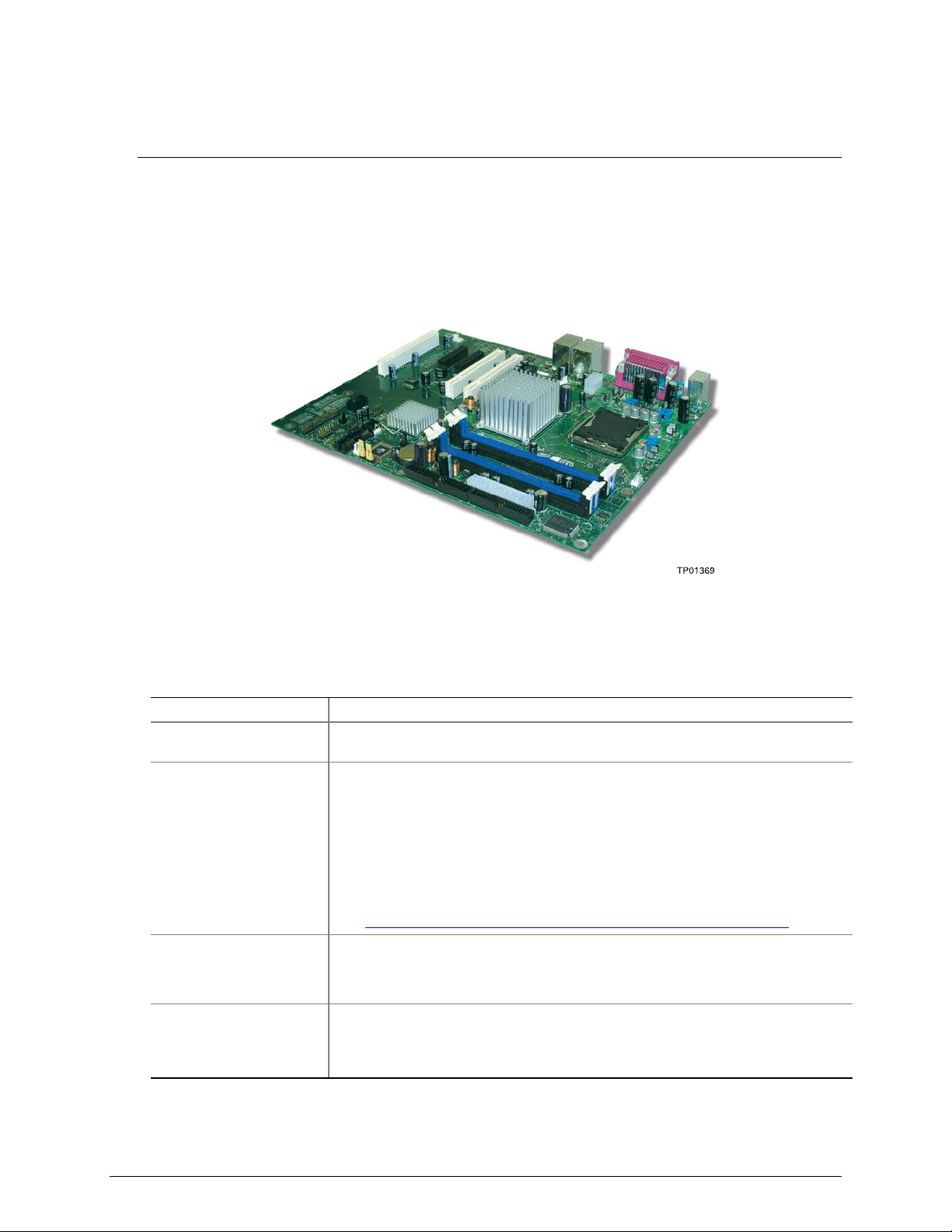
1 Server Board Features
This chapter briefly describes the main features of the Intel® Entry Server Board SE7221BA1-E.
Provided is a photograph of the product, a list of the server board features, and diagrams showing
the location of important components and connections on the server board.
The Intel® Entry Server Board SE7221BA1-E is shown in the following picture.
Figure 1. Intel® Entry Server Board SE7221BA1-E
Table 1 summarizes the major features of the server board.
Table 1. Server Board Features
Feature Description
Processors Support for an Intel® Pentium® 4 processor in the LGA775 package with 800
MHz or 533 MHz front side bus
Memory
Four 240-pin, 1.8 V SDRAM Dual Inline Memory Module (DIMM) sockets
533/400 MHz single or dual channel DDR2 SDRAM interface
Designed to support up to 4 GB of system memory
NOTE: System resources (such as PCI and PCI Express*) require physical
memory address locations that reduce available memory addresses above 3
GB. This may result in less than 4 GB of memory being available to the
operating system and applications. For the latest list of tested memory, refer
to the Intel World Wide Web site at:
http://support.Intel.com/support/motherboards/server/SE7221BA1-E/
Chipset Intel® E7221 Chipset consisting of:
Intel® E7221 Graphics Memory Controller Hub (MCH with integrated graphics)
Intel® 82801FR I/O Controller Hub (ICH6-R)
Peripheral Interfaces
Up to eight USB 2.0 ports
Four ports routed to the back panel
Four ports routed to two USB headers
Intel® Entry Server Board SE7221BA1-E User Guide 1
Page 13
Server Board Features
Feature Description
Four Serial ATA channels, via the ICH6-R, one device per channel
One IDE interface with ATA-66/100 support
One diskette drive interface
One parallel port
One serial port
PS/2* keyboard and mouse ports
LAN
Marvell* 88E8050 PCI Express* Gigabit Ethernet Controller (10/100/1000
Mbit/sec) with RJ-45 connector
Intel® 82551QM 10/100 Ethernet Controller with RJ-45 connector
Expansion Capabilities
Three PCI bus add-in card connectors (SMBus routed to PCI bus connector 2)
One PCI Express* x8
Two PCI Express* x1 using x4 connectors
Four Serial ATA (SATA) connectors
Two front panel USB 2.0 headers
BIOS
8 Mbit symmetrical flash memory
Support for SMBIOS
Intel® Rapid BIOS Boot
Intel® Express BIOS Update
Power Management
Support for Advanced Configuration and Power Interface (ACPI)
Suspend to RAM (STR)
Wake on USB, PCI, PCI Express*, PS/2, LAN, and front panel
Server Management Hardware monitor with:
Four fan sensing inputs used to monitor fan activity
Remote diode temperature sensing
Intel® Precision Cooling Technology fan speed control that automatically
adjusts processor fan speeds based on processor temperature and chassis fan
speeds based on system temperature
Voltage sensing to detect out of range values
2 Intel® Entry Server Board SE7221BA1-E User Guide
Page 14
Server Board Features
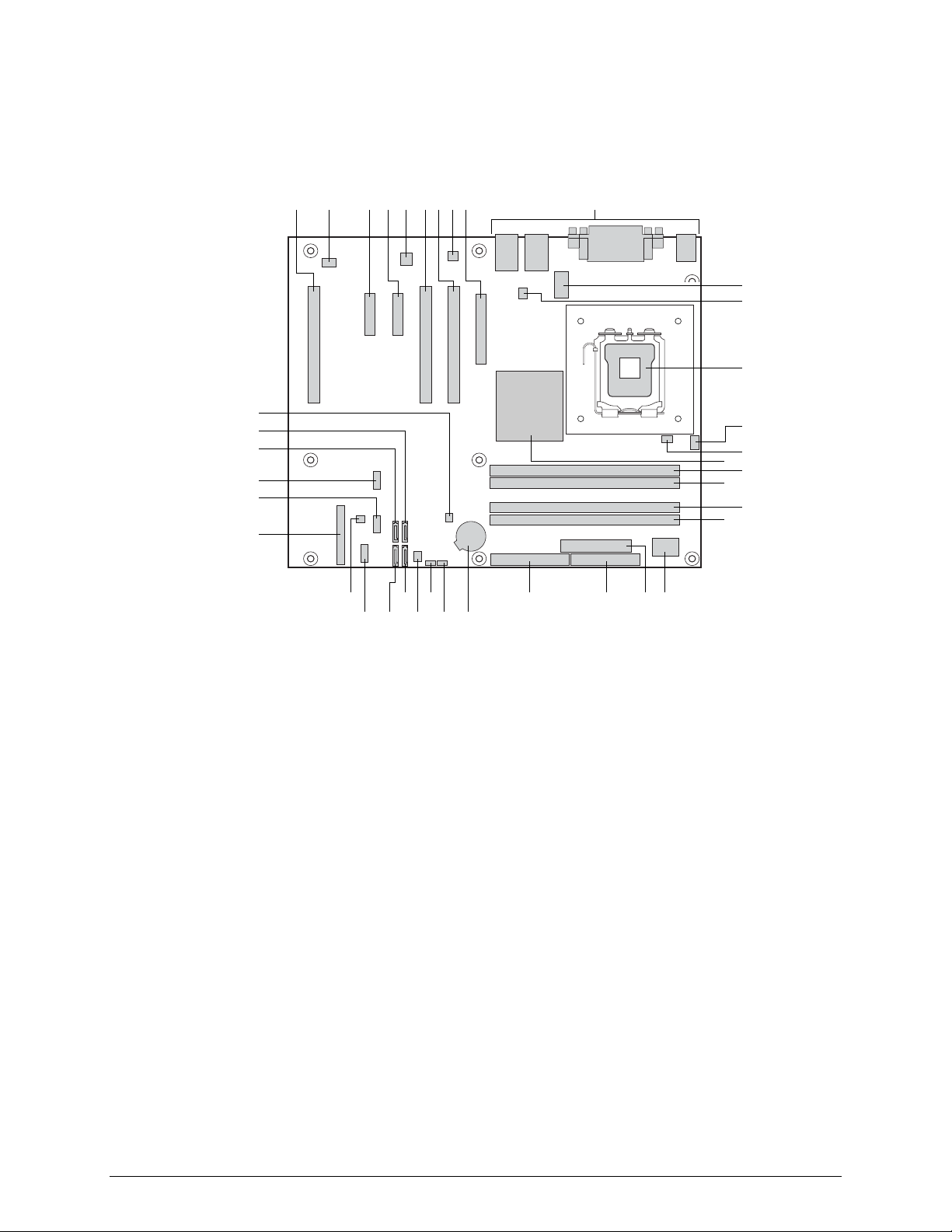
Connector and Component Locations
JB E HA FC D G I
K
L
M
LL
KK
JJ
II
HH
N
O
P
Q
R
S
T
GG
AA
EE
DD
CC
BB
Y
Z
FF
A: Conventional PCI Slot 3 K: 2 x 4 Power Connector
B: Rear Fan Connector L: Vreg Fan Connector U: I/O Controller DD: SATA 2 Connector
C: PCIE* Slot 2 (x4
Connector)
D: PCIE* Slot 1 (x4
Connector)
E: Intel® 82551QM LAN
Contoller
F: Conventional PCI Slot 2
G: Conventional PCI Slot 1
H: Marvell* Yukon* 88E8050
PCI Express* Gigabit
Ethernet Controller
I: PCI Express* 1 x8 Slot
J: Back Panel I/O
M: LGA775 Processor
Socket
N: CPU Fan Connector W: Diskette Drive Connector
O: Hardware Management
Controller
P: Intel® E7221 MCH with
integrated graphics
Q: Channel A DIMM 0
Socket (blue)
R: Channel A DIMM 1
Socket (black)
S: Channel B DIMM 0
Socket (blue)
X W
T: Channel B DIMM 0 Socket
(black)
V: 2 x 12 Power Connector EE: Serial B Connector
X: Parallel ATA IDE
Connector
Y: Battery HH: Front Panel USB 2
Z: BIOS Configuration
Jumper
AA: Clear CMOS Jumper
BB: Front Fan Connector KK: SATA 1 Connector
V U
TP01370
CC: SATA 3 Connector
FF: SCSI LED
Connector
GG: Front Panel
Connector
II: Front Panel USB 1
JJ: SATA 0 Connector
LL: Chassis Intrusion
Connector
Figure 2. Server Board Connector and Component Locations
Intel® Entry Server Board SE7221BA1-E User Guide 3
Page 15
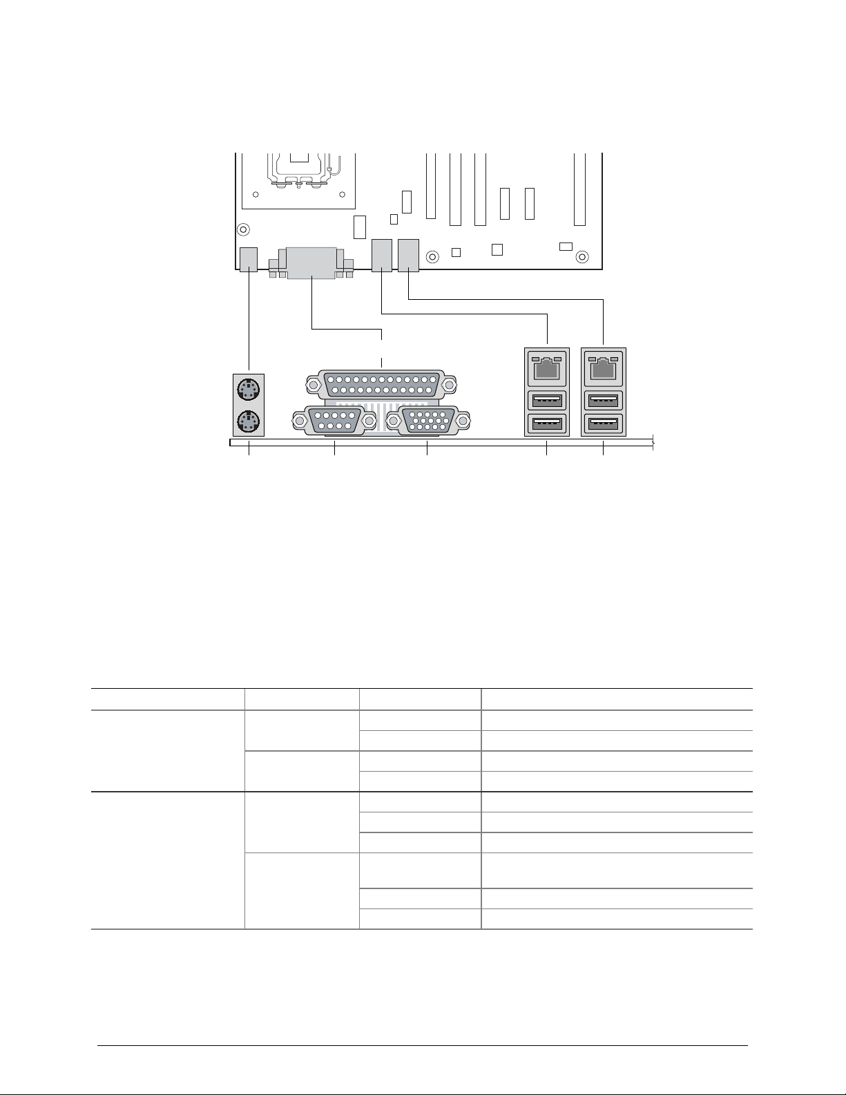
Back Panel Connectors
Server Board Features
C
DB FA E
A Keyboard / Mouse D Video
B Serial Port A E Intel® 82551QM (10/100) / USB 0, 1
C Parallel Port F Marvell* 88E8050 (Gigabit) / USB 2, 3
Figure 3. Back Panel Connectors
The NIC LEDs at the right and left of each NIC provide the following information:
Table 2. NIC LEDs
NIC LED Color LED State Description
Intel® 82551QM (10/100
Mbit)
Marvell* 88E8050
(Gigabit)
Left LED
Right LED
Left LED
Right LED
Off 10 Mbps connection (if right LED is on)
Solid Green 100 Mbps connection
On Network connection in place
Blinking Green Transmit/receive activity
Off No network connection
Solid Amber Network connection in place
Blinking Amber Transmit/receive activity
Off 10 Mbps connection (if left LED is on or
blinking)
Solid Amber 100 Mbps connection
Solid Green 1000 Mbps connection
TP01371
4 Intel® Entry Server Board SE7221BA1-E User Guide
Page 16

Server Board Features
Hardware Requirements
To avoid integration difficulties and possible board damage, your system must meet the
requirements outlined below. For a list of qualified components, see the links under “Additional
Information and Software.”
Processor
NOTE
Failure to use an EPS12 V or ATX12 V power supply or not connecting the
12 V (2x4) power connector to SE7221BA1-E server board may result in the
computer not booting.
The Intel® Entry Server Board SE7221BA1-E supports a single Intel® Pentium® 4 processor in
the LGA775 package. Processors are not included with the Server board and must be purchased
separately.
The processor connects to the Intel® Entry Server Board through the LGA775 socket.
The supported processors list for Intel® Entry Server Board SE7221BA1-E is located on the web
at:
http://support.Intel.com/support/motherboards/server/SE7221BA1-E/.
Memory
NOTE
To be fully compliant with all applicable Intel® SDRAM memory
specifications, the Server board should be populated with DIMMs that
support the Serial Presence Detect (SPD) data structure. If your memory
modules do not support SPD, you will see a notification to this effect on the
screen at power up. The BIOS will attempt to configure the memory
controller for normal operation.
The Intel® Entry Server Board SE7221BA1-E supports dual or single channel memory
configurations defined in the table below, with four 240-pin Double Data Rate 2 (DDR2) SDRAM
Dual Inline Memory Module (DIMMs) connectors with gold-plated contacts.
Support for:
o Unbuffered, non-registered single or double-sided DIMMs
o ECC or Non-ECC DIMMs
o Serial Presence Detect (SPD) memory only
o V memory
Memory configuration:
o Up to 2.0 GB utilizing 256 Mb technology
o Up to 4.0 GB utilizing 512 Mb or 1 Gb technology
Intel® Entry Server Board SE7221BA1-E User Guide 5
Page 17

Server Board Features
NOTE
System resources (such as PCI and PCI Express*) require physical memory
address locations that reduce available memory addresses above 3 GB. This
may result in less than 4 GB of memory being available to the operating
system and applications.
For a complete list of supported memory DIMMs, see the links under “Additional Information and
Software.”
Power Supply
A minimum of 350 Watts is required. Your supply must provide a minimum of 1.2 A of 5 V
standby current or the board will not boot.
NOTE
PCI Express* Card Electromechanical Specification Revision 1.0a, April 15, 2003 states, in part:
OWNSHIFTING, WHICH IS DEFINED AS PLUGGING A PCI EXPRESS* CARD INTO A
D
CONNECTOR THAT IS NOT FULLY ROUTED FOR ALL OF THE
GENERAL IS NOT ALLOWED. THE EXCEPTION IS THE X8 CONNECTOR WHICH THE
SYSTEM DESIGNER MAY CHOOSE TO ROUTE ONLY THE FIRST FOUR
. A X8 CARD FUNCTIONS AS A X4 CARD IN THIS SCENARIO.
LANES
PCI EXPRESS* LANES, IN
PCI EXPRESS*
The Intel Server Board SE7221BA1-E features two PCI Express* x4 connectors, each routed with a
x1 lane and limited to x1 throughput.
6 Intel® Entry Server Board SE7221BA1-E User Guide
Page 18

Hardware Installations and Upgrades
2 Hardware Installations and Upgrades
Before You Begin
Cautions and Warnings indicate conditions that, if not observed, can cause personal injury.
The procedures in this chapter assume familiarity with the general terminology associated with
personal computers and with the safety practices and regulatory compliance required for using and
modifying electronic equipment.
Disconnect the computer or server from its power source and from any telecommunications links,
networks, or modems before performing any of the procedures described in this chapter. Failure to do
so can result in personal injury or equipment damage. Some circuitry on the board can continue to
operate even though the front panel power button is off.
Follow these guidelines before you begin:
Always follow the steps in each procedure in the correct order.
Set up a log to record information about your computer, such as model, serial numbers, installed
options, and configuration information.
Electrostatic discharge (ESD) can damage components. Perform the procedures described in this
chapter only at an ESD workstation using an antistatic wrist strap and a conductive foam pad. If
such a station is not available, you can provide some ESD protection by wearing an antistatic
wrist strap and attaching it to a metal part of the computer chassis.
Installation Precautions
When you install and test your new server board, observe all warnings and cautions.
To avoid injury, be careful of:
Sharp pins on connectors
Sharp pins on printed circuit assemblies
Rough edges and sharp corners on the chassis
Hot components (like processors, voltage regulators, and heat sinks)
Damage to wires that could cause a short circuit
Observe all warnings and cautions that instruct you to refer computer servicing to qualified
technical personnel.
Intel® Entry Server Board SE7221BA1-E User Guide 7
Page 19

Hardware Installations and Upgrades
Tools and Supplies Needed
Phillips (cross head) screwdriver (#1 bit and #2 bit)
Needle nosed pliers
A ruler
Pen or pencil
Antistatic wrist strap and conductive foam pad (recommended)
Installing and Removing Memory
CAUTION
To be fully compliant with all applicable Intel® SDRAM memory
specifications, the board requires DIMMs that support the Serial Presence
Detect (SPD) data structure.
Intel® Entry Server Board SE7221BA1-E has four 240-pin DIMM sockets arranged as DIMM 0
and DIMM 1 in both Channel A and Channel B, as shown in Figure 7.
Guidelines for Dual Channel Memory Configuration
Before installing DIMMs, read and follow these guidelines for dual channel configuration.
Two or Four DIMMs
Install a matched pair of DIMMs equal in speed and size in DIMM 0 (blue) of both channels A and
B (see Figure 4).
Channel A
1 GB, 400 MHz DIMM 0
DIMM 1
Channel B
1 GB, 400 MHz DIMM 0
DIMM 1
Figure 4. Dual Configuration Example 1
8 Intel® Entry Server Board SE7221BA1-E User Guide
Page 20

Hardware Installations and Upgrades
If additional memory is to be used, install another matched pair of DIMMs in DIMM 1 (black) in
both channels A and B (see Figure 5).
Channel A
256 MB, 400 MHz DIMM 0
512 MB, 400 MHz
Channel B
256 MB, 400 MHz DIMM 0
512 MB, 400 MHz
Figure 5. Dual Configuration Example 2
NOTE
DIMM 1
DIMM 1
All other memory configurations will result in single channel memory
operation.
Installing DIMMs
CAUTION
Install memory in the DIMM sockets prior to installing the PCI Express* x8
card to avoid interference with the memory retention mechanism.
To make sure you have the correct DIMM, place the DIMM on the illustration in Figure 6 showing
the DDR2 DIMM. All the notches should match with the DDR2 DIMM.
Figure 6. Use DDR2 DIMMs
To install DIMMs, follow these steps:
1. Observe the precautions in "Safety Information" at the beginning of this document.
2. Turn off all peripheral devices connected to the computer. Turn off the computer and
disconnect the AC power cord.
3. Remove the computer’s cover and locate the DIMM sockets.
Intel® Entry Server Board SE7221BA1-E User Guide 9
Page 21
Hardware Installations and Upgrades
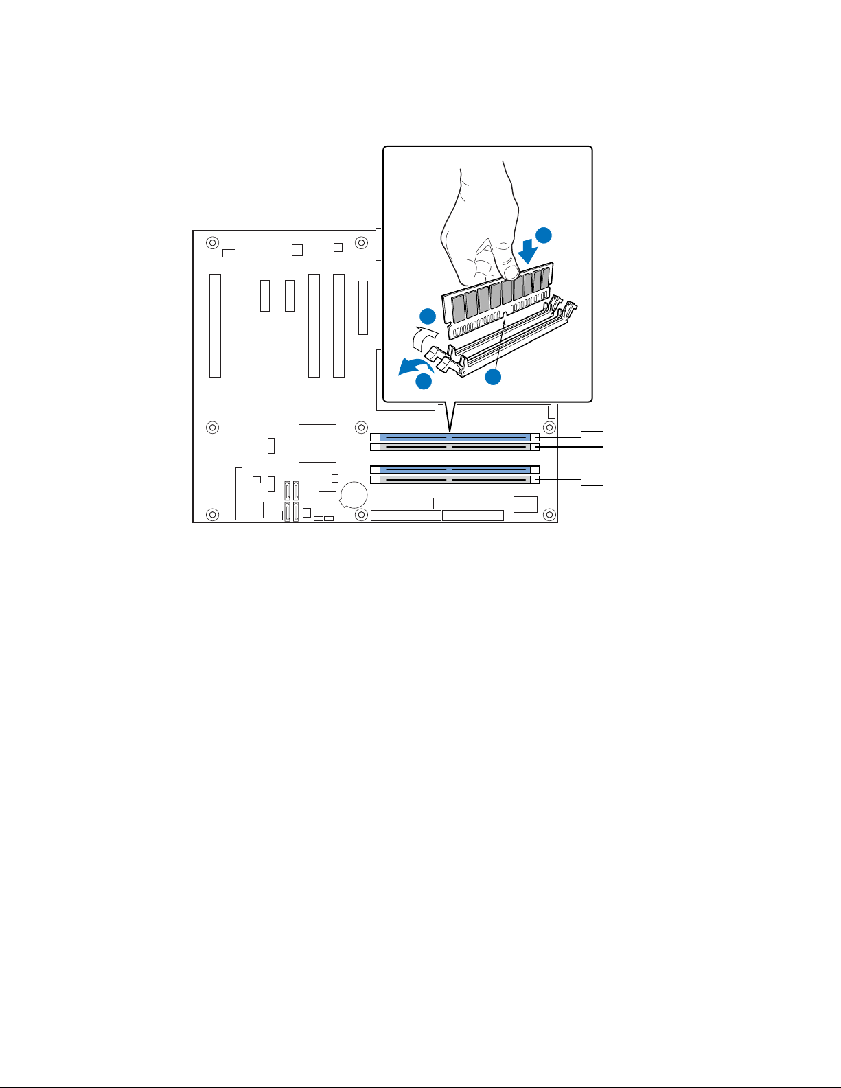
4. Remove the PCI Express* card if it interferes with the DIMM retaining clips from being easily
opened and closed.
C
D
A
Figure 7. Installing a DIMM
B
Channel A, DIMM 0
Channel A, DIMM 1
Channel B, DIMM 0
Channel B, DIMM 1
TP01373
5. Make sure the clips at either end of the DIMM socket(s) are pushed outward to the
open position.
6. Holding the DIMM by the edges, remove it from its anti-static package.
7. Position the DIMM above the socket. Align the small notch at the bottom edge of the DIMM
with the keys in the socket (see inset in Figure 7).
8. Insert the bottom edge of the DIMM into the socket.
9. When the DIMM is inserted, push down on the top edge of the DIMM until the retaining clips
snap into place. Make sure the clips are firmly in place.
10. Reinstall the PCI Express* x8 card if it was removed prior to installing the DIMMs.
11. Replace the computer’s cover and reconnect the AC power cord.
Removing DIMMs
To remove a memory module, follow these steps:
1. Observe the precautions in "Safety Information" at the beginning of this document.
2. Turn off all peripheral devices connected to the computer, then turn off the computer.
3. Remove the AC power cord from the computer.
4. Remove the computer’s cover.
5. Remove the PCI Express* x8 card if it interferes with the DIMM clips from being easily
opened and closed.
10 Intel® Entry Server Board SE7221BA1-E User Guide
Page 22

Hardware Installations and Upgrades
6. Gently spread the retaining clips at each end of the DIMM socket. The DIMM pops out of
the socket.
7. Hold the DIMM by the edges, lift it away from the socket, and store it in an anti-static package.
8. Reinstall and reconnect any parts you removed or disconnected to reach the DIMM sockets.
9. Replace the computer’s cover and reconnect the AC power cord.
Installing or Replacing the Processor
NOTES
Use the instructions provided below to install or replace a processor instead
of using the instructions that came with the processor.
CAUTIONS
Processor must be appropriate: You may damage the server board if
you install a processor that is inappropriate for your server. See “Additional
Information and Software” for a link to the list of compatible processor(s).
ESD and handling processors: Reduce the risk of electrostatic
discharge (ESD) damage to the processor by doing the following: (1) Touch
the metal chassis before touching the processor or server board. Keep part of
your body in contact with the metal chassis to dissipate the static charge
while handling the processor. (2) Avoid moving around unnecessarily.
Installing a Processor
CAUTION
Before installing or removing the processor, make sure that AC power has
been removed by unplugging the power cord from the computer; the standby
power LED should not be lit. Failure to do so could damage the processor
and the board.
To install a processor, follow these instructions:
1. Observe the precautions in "Safety Information" at the beginning of this document.
2. Open the socket lever by pushing the lever down and away from the socket.
TP01374
Figure 8. Lift Socket Lever
Intel® Entry Server Board SE7221BA1-E User Guide 11
Page 23

Hardware Installations and Upgrades
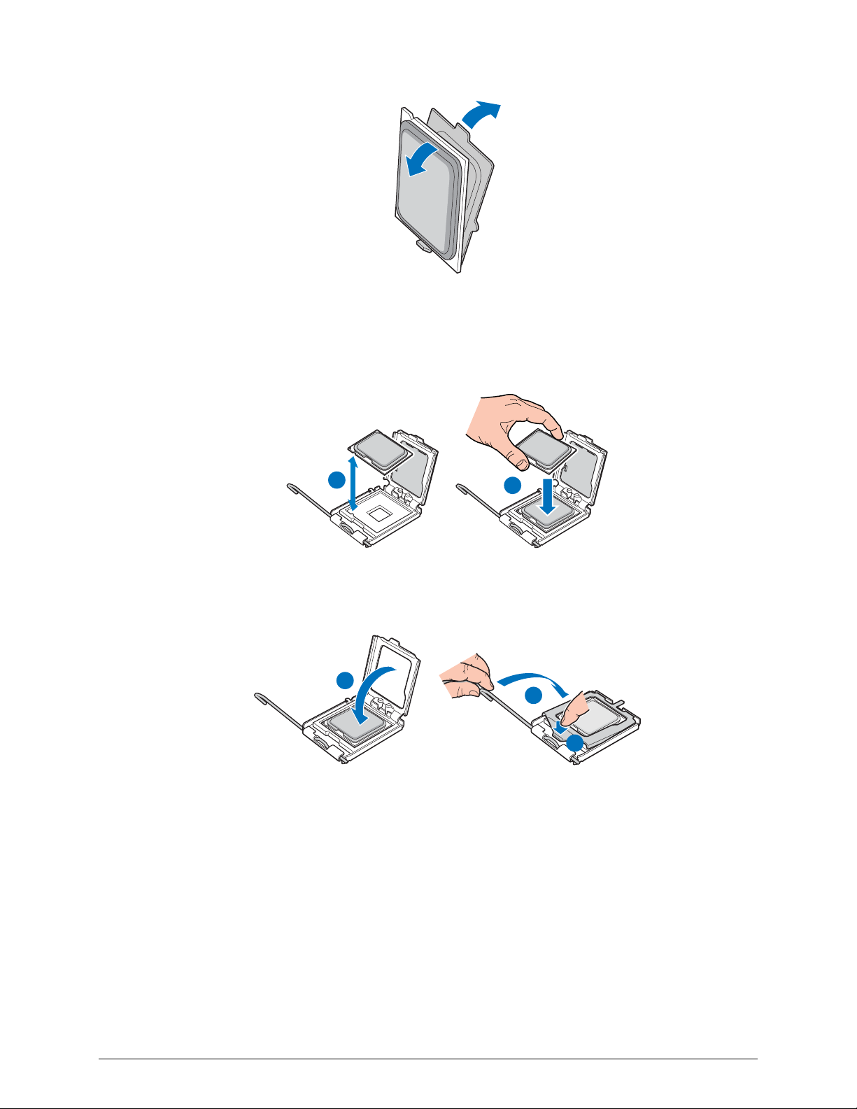
3. Lift the load plate. Do not touch the socket contacts.
Figure 9. Lift the Load Plate
4. Remove the protective socket cover from the load plate. Do not discard the protective socket
cover. Always replace the socket cover if the processor is removed from the socket.
A
B
TP01376
Figure 10. Remove the Protective Socket Cover
5. Remove the processor from the protective processor cover. Hold the processor only at the
edges, being careful not to touch the bottom of the processor. Do not discard the protective
processor cover. Always replace the processor cover if the processor is removed from the
socket.
12 Intel® Entry Server Board SE7221BA1-E User Guide
Page 24
Hardware Installations and Upgrades
TP01377
Figure 11. Remove the Processor from the Protective Processor Cover
6. Hold the processor with your thumb and index fingers oriented as shown in Figure 12. Make
sure fingers align to the socket cutouts. Align notches with the socket. Lower the processor
straight down without tilting or sliding the processor in the socket.
A
Figure 12. Install Processor
7. Pressing down on the load plate close and engage the socket lever.
A
Figure 13. Close the Load Plate
B
TP01378
C
B
TP01379
Installing the Processor Fan Heat Sink
The Intel® Entry Server Board SE7221BA1-E has an integrated processor fan heat sink retention
mechanism (RM). For instructions on how to attach the processor fan heat sink to the integrated
Intel® Entry Server Board SE7221BA1-E User Guide 13
Page 25

Hardware Installations and Upgrades
processor fan heat sink RM, refer to the boxed processor manual or the Intel World Wide Web
site at:
http://support.Intel.com/support/processors/pentium4/intnotes478.htm
Connecting the Processor Fan Heat Sink Cable
Connect the processor fan heat sink cable to the 4-pin processor fan header.
TP01380
Figure 14. Connecting the Processor Fan Heat Sink Cable
Removing the Processor
For instruction on how to remove the processor fan heat sink and processor, refer to the processor
installation manual or Intel support at:
http://support.Intel.com/support/processors/pentium4/intnotes478.htm
Installing and Removing a PCI Express* x8 Card
CAUTION
When installing any PCI Express* x8 card on the server board, ensure that it
is fully seated in the PCI Express* x8 connector before you power on the
system. If the card is not fully seated in the connector, an electrical short
may result across the connector pins. Depending on the over-current
protection of the power supply, certain board components and/or traces may
Installing a PCI Express* x8 Card
be damaged.
Follow these instructions to install a PCI Express* x8 card:
1. Observe the precautions in "Safety Information" at the beginning of this document.
2. Place the card in the PCI Express* x8 connector.
3. Press down on the card until it is completely seated in the connector.
14 Intel® Entry Server Board SE7221BA1-E User Guide
Page 26

Hardware Installations and Upgrades
4. Secure the card’s metal bracket to the chassis back panel with a screw.
Removing the PCI Express* x8 Card
Follow these instructions to remove the PCI Express* x8 card from the RM:
1. Observe the precautions in "Safety Information" at the beginning of this document.
2. Remove the screw that secures the card’s metal bracket to the chassis back panel.
3. Push back on the RM lever until the retention pin completely clears the notch in the card.
4. Pull the card straight up.
Replacing the Backup Battery
A coin-cell battery (CR2032) powers the real-time clock and CMOS memory. When the server is
not AC powered-on, the battery has an estimated life of three years. When the server is poweredon, the standby current from the power supply extends the life of the battery. The clock is accurate
to ± 13 minutes/year at 25 ºC with 3.3 VSB applied.
When the voltage drops below a certain level, the BIOS Setup program settings stored in CMOS
RAM (for example, the date and time) might not be accurate. Replace the battery with an
equivalent one. Figure 15 shows the location of the battery.
1. Observe the precautions in "Safety Information" at the beginning of this document.
2. Turn off all peripheral devices connected to the server. Turn off the server.
3. Disconnect the AC power cord from the server.
4. Remove the server’s cover and locate the battery.
5. Insert the tip of a small flat bladed screwdriver, or an equivalent, under the tab in the plastic
retainer. Gently push down on the screwdriver to lift the battery.
6. Remove the battery from its socket.
7. Dispose of the battery according to local ordinance.
8. Remove the new lithium battery from its package, and, being careful to observe the correct
polarity, insert it in the battery socket.
9. Close the chassis.
10. Run Setup to restore the configuration settings to the RTC.
Intel® Entry Server Board SE7221BA1-E User Guide 15
Page 27

Hardware Installations and Upgrades
Figure 15. Replacing the Backup Battery
TP01382
CAUTION
Risk of explosion if the battery is replaced with an incorrect type. Batteries
should be recycled where possible. Disposal of used batteries must be in
accordance with local environmental regulations.
PRÉCAUTION
Risque d'explosion si la pile usagée est remplacée par une pile de type
incorrect. Les piles usagées doivent être recyclées dans la mesure du
possible. La mise au rebut des piles usagées doit respecter les
réglementations locales en vigueur en matière de protection de
l'environnement.
WARNING FORHOLDSREGEL
Eksplosionsfare, hvis batteriet erstattes med et batteri af en forkert type.
Batterier bør om muligt genbruges. Bortskaffelse af brugte batterier bør
foregå i overensstemmelse med gældende miljølovgivning.
WARNING OBS!
Det kan oppstå eksplosjonsfare hvis batteriet skiftes ut med feil type. Brukte
batterier bør kastes i henhold til gjeldende miljølovgivning.
WARNING VIKTIGT!
Risk för explosion om batteriet ersätts med felaktig batterityp. Batterier ska
kasseras enligt de lokala miljövårdsbestämmelserna.
16 Intel® Entry Server Board SE7221BA1-E User Guide
Page 28
VARO
Räjähdysvaara, jos pariston tyyppi on väärä. Paristot on kierrätettävä, jos se
on mahdollista. Käytetyt paristot on hävitettävä paikallisten
ympäristömääräysten mukaisesti.
VORSICHT
Bei falschem Einsetzen einer neuen Batterie besteht Explosionsgefahr. Die
Batterie darf nur durch denselben oder einen entsprechenden, vom Hersteller
empfohlenen Batterietyp ersetzt werden. Entsorgen Sie verbrauchte
Batterien den Anweisungen des Herstellers entsprechend.
AVVERTIMENTO
Esiste il pericolo di un esplosione se la pila non viene sostituita in modo
corretto. Utilizzare solo pile uguali o di tipo equivalente a quelle consigliate
dal produttore. Per disfarsi delle pile usate, seguire le istruzioni del
produttore.
PRECAUCIÓN
Existe peligro de explosión si la pila no se cambia de forma adecuada.
Utilice solamente pilas iguales o del mismo tipo que las recomendadas por el
fabricante del equipo. Para deshacerse de las pilas usadas, siga igualmente
las instrucciones del fabricante.
Hardware Installations and Upgrades
WAARSCHUWING
Er bestaat ontploffingsgevaar als de batterij wordt vervangen door een
onjuist type batterij. Batterijen moeten zoveel mogelijk worden gerecycled.
Houd u bij het weggooien van gebruikte batterijen aan de plaatselijke
milieuwetgeving.
ATENÇÃO
Haverá risco de explosão se a bateria for substituída por um tipo de bateria
incorreto. As baterias devem ser recicladas nos locais apropriados. A
eliminação de baterias usadas deve ser feita de acordo com as
regulamentações ambientais da região.
AŚCIAROŽZNAŚĆ
Існуе рызыка выбуху, калі заменены акумулятар неправільнага тыпу.
Акумулятары павінны, па магчымасці, перепрацоўвацца. Пазбаўляцца
ад старых акумулятараў патрэбна згодна з мясцовым заканадаўствам па
экалогіі.
UPOZORNÌNÍ
V případě výměny baterie za nesprávný druh může dojít k výbuchu. Je-li to
možné, baterie by měly být recyklovány. Baterie je třeba zlikvidovat v
souladu s místními předpisy o životním prostředí.
Intel® Entry Server Board SE7221BA1-E User Guide 17
Page 29

VIGYÁZAT
Hardware Installations and Upgrades
Προσοχή
Υπάρχει κίνδυνος για έκρηξη σε περίπτωση που η µπαταρία αντικατασταθεί
από µία λανθασµένου τύπου. Οι µπαταρίες θα πρέπει να ανακυκλώνονται
όταν κάτι τέτοιο είναι δυνατό. Η απόρριψη των χρησιµοποιηµένων
µπαταριών πρέπει να γίνεται σύµφωνα µε τους κατά τόπο περιβαλλοντικούς
κανονισµούς.
Ha a telepet nem a megfelelő típusú telepre cseréli, az felrobbanhat. A
telepeket lehetőség szerint újra kell hasznosítani. A használt telepeket a helyi
környezetvédelmi előírásoknak megfelelően kell kiselejtezni.
AWAS
Risiko letupan wujud jika bateri digantikan dengan jenis yang tidak betul.
Bateri sepatutnya dikitar semula jika boleh. Pelupusan bateri terpakai
mestilah mematuhi peraturan alam sekitar tempatan.
OSTRZEŻENIE
Istnieje niebezpieczeństwo wybuchu w przypadku zastosowania
niewłaściwego typu baterii. Zużyte baterie należy w miarę możliwości
utylizować zgodnie z odpowiednimi przepisami ochrony środowiska.
PRECAUŢIE
Risc de explozie, dacă bateria este înlocuită cu un tip de baterie
necorespunzător. Bateriile trebuie reciclate, dacă este posibil. Depozitarea
bateriilor uzate trebuie să respecte reglementările locale privind protecţia
mediului.
ВНИМАНИЕ
При использовании батареи несоответствующего типа существует риск
ее взрыва. Батареи должны быть утилизированы по возможности.
Утилизация батарей должна проводится по правилам, соответствующим
местным требованиям.
UPOZORNENIE
Ak batériu vymeníte za nesprávny typ, hrozí nebezpečenstvo jej výbuchu.
Batérie by sa mali podľa možnosti vždy recyklovať. Likvidácia použitých
batérií sa musí vykonávať v súlade s miestnymi predpismi na ochranu
životného prostredia.
18 Intel® Entry Server Board SE7221BA1-E User Guide
Page 30

POZOR
Zamenjava baterije z baterijo drugačnega tipa lahko povzroči eksplozijo.
Če je mogoče, baterije reciklirajte. Rabljene baterije zavrzite v skladu z
lokalnimi okoljevarstvenimi predpisi.
การระวัง
ระวังการระเบิดที่เกิดจากเปลี่ยนแบตเตอรี่ผิดประเภท หากเป็นไปได้
ควรนำแบตเตอรี่ไปรีไซเคิล
การทิ้งแบตเตอรี่ใช้แล้วต้องเป็นไปตามกฎข้อบังคับด้านสิ่งแวดล้อมของท้องถิ่น.
UYARI
Yanlış türde pil takıldığında patlama riski vardır. Piller mümkün olduğunda
geri dönüştürülmelidir. Kullanılmış piller, yerel çevre yasalarına uygun
olarak atılmalıdır.
OСТОРОГА
Використовуйте батареї правильного типу, інакше існуватиме ризик
вибуху.
Якщо можливо, використані батареї слід утилізувати. Утилізація
використаних батарей має бути виконана згідно місцевих норм, що
регулюють охорону довкілля.
Hardware Installations and Upgrades
ETTEVAATUST
Intel® Entry Server Board SE7221BA1-E User Guide 19
Page 31

ATTENZJONI
UPOZORNENIE
Hardware Installations and Upgrades
20 Intel® Entry Server Board SE7221BA1-E User Guide
Page 32

Server Utilities
3 Server Utilities
Using the BIOS Setup Utility
The BIOS Setup program is accessed by pressing the <F2> key after the Power-On Self-Test
(POST) memory test begins and before the operating system boot begins. For the latest BIOS Setup
menu options, go to the Intel World Wide Web site:
http://support.Intel.com/support/motherboards/server/SE7221BA1-E/.
Setting the BIOS Configuration Jumper Block
CAUTION
Always turn off the power and unplug the power cord from the computer
before changing the jumper. Moving the jumper with the power on may
result in unreliable computer operation.
The three-pin BIOS jumper block enables all board configurations to be done in BIOS Setup. Table 3
shows the jumper settings for the Setup program modes.
Table 3. Jumper Settings for the BIOS Setup Program Modes
Jumper Setting Mode Description
3
1
1
3
1
3
Normal
(default) (1-2)
Configure (2-3) After the Power-On Self-Test (POST) runs, the BIOS displays the
Recovery
(None)
The BIOS uses the current configuration and passwords for booting.
Maintenance Menu. Use this menu to clear passwords.
The BIOS recovers data from a recovery diskette in the event of a
failed BIOS update.
Clearing Passwords
This procedure assumes that the board is installed in the computer and the configuration jumper
block is set to normal mode.
1. Observe the precautions in "Safety Information" at the beginning of this document.
2. Turn off all peripheral devices connected to the computer. Turn off the computer. Disconnect
the computer’s power cord from the AC power source (wall outlet or power adapter).
3. Remove the computer cover.
4. Find the configuration jumper block.
Intel® Entry Server Board SE7221BA1-E User Guide 21
Page 33

Server Utilities
5. Place the jumper on pins 2-3 as shown below.
3
1
6. Replace the cover, plug in the computer, turn on the computer, and allow it to boot.
7. The computer starts the Setup program. Setup displays the Maintenance menu.
8. Use the arrow keys to select Clear Passwords. Press <Enter> and Setup displays a pop-up
screen requesting that you confirm clearing the password. Select Yes and press <Enter>.
Setup displays the maintenance menu again.
9. Press <F10> to save the current values and exit Setup.
10. Turn off the computer. Disconnect the computer’s power cord from the AC power source.
11. Remove the computer cover.
12. To restore normal operation, place the jumper on pins 1-2 as shown below.
1
13. Replace the cover, plug in the computer, and turn on the computer.
3
Updating the BIOS
The BIOS can be updated by using the Iflash Memory Update utility.
Updating the BIOS with the Iflash Memory Update Utility
With the Iflash BIOS update utility you can update the system BIOS from a floppy disk or other
bootable media. The utility available from the Web provides a simple method for creating a
bootable flash memory update floppy that will automatically update your BIOS.
Obtaining the BIOS Update File
You can update to a new version of the BIOS by using the BIOS update file. The BIOS update file
is a compressed self-extracting archive that contains all the files you need to update the BIOS. The
BIOS update file contains:
New BIOS files
BIOS recovery files
Intel® Flash Memory Update Utility
You can obtain the BIOS update file through your computer supplier or by navigating to the Server
Board SE7221BA1-E page on the Intel World Wide Web site at:
http://support.Intel.com/support/motherboards/server/SE7221BA1-E/
Navigate to the SE7221BA1-E page, click “[view] Latest BIOS updates,” and select the Iflash BIOS
Update utility file.
NOTE
Review the instructions distributed with the update utility before attempting a
BIOS update.
22 Intel® Entry Server Board SE7221BA1-E User Guide
Page 34

The Iflash Memory Update utility allows you to:
Update the BIOS in flash memory
Update the language section of the BIOS
Updating the BIOS
CAUTION
The AUTOEXEC.BAT file provided with the update files updates the BIOS.
Do not interrupt the process or the system may not function.
1. Boot the computer with the BIOS update diskette in drive A. During system boot, the
AUTOEXEC.BAT file provided with the update files will automatically run the BIOS update
process.
2. When the update process is complete, the monitor will display a message telling you to remove
the diskette and to reboot the system.
3. As the computer boots, check the BIOS identifier (version number) to make sure the update
was successful. If a logo appears, press <Esc> to view the POST messages.
Server Utilities
Recovering the BIOS
It is unlikely that anything will interrupt the BIOS update; however, if an interruption occurs, the
BIOS could be damaged. The following steps explain how to recover the BIOS if an update fails.
The following procedure uses recovery mode for the Setup program.
NOTE
Because of the small amount of code available in the boot block area, there is
no video support. You will not see anything on the screen during this
procedure. Monitor the procedure by listening to the speaker and looking at
the diskette drive LED.
1. Turn off the computer, disconnect the computer’s power cord, and disconnect all external
peripherals.
2. Remove the computer cover and locate the configuration jumper block.
3. Remove the jumper from all pins as shown below to set recovery mode for Setup.
1
3
4. Insert the bootable BIOS update diskette into diskette drive A.
5. Replace the computer cover, connect the power cord, turn on the computer, and allow it to
boot. The recovery process will take a few minutes.
6. Listen to the speaker:
• Upon applying power, drive A will begin to show activity. In about a minute, two beeps
are heard and drive A activity ceases (temporarily) indicating the successful recovery of the
BIOS core. Drive A activity will begin again followed by two more beeps indicating the
Intel® Entry Server Board SE7221BA1-E User Guide 23
Page 35

Server Utilities
successful recovery of the boot block. This sequence of events indicates a successful BIOS
recovery.
• A series of continuous beeps indicates a failed BIOS recovery.
7. If recovery fails, return to step 1 and repeat the recovery process.
8. If recovery is successful, turn off the computer, and disconnect its power cord.
9. Remove the computer cover and continue with the following steps.
10. On the jumper block, reinstall the jumper back on pins 1-2 as shown below to set normal mode
for Setup.
3
1
11. Leave the update diskette in drive A, replace the computer cover, and connect the computer’s
power cord.
12. Turn on the computer and continue with the BIOS update.
24 Intel® Entry Server Board SE7221BA1-E User Guide
Page 36

Troubleshooting
4 Troubleshooting
This chapter helps you identify and solve problems that might occur while you are using the
system.
For any issue, first ensure you are using the latest firmware and files. Firmware upgrades include
updates for BIOS, the baseboard management controller (BMC), and the hot-swap controller
(HSC). See “Additional Information and Software” for a link to the software updates. In addition to
the server firmware and files, also update any drivers used for components you have installed in
your system, such as video drivers, network drivers, and SCSI drivers.
Intel provides a package called the “Platform Confidence Test” that may help with your
diagnostics. See “Additional Information and Software” for a link to this software.
If you are unable to resolve your server problems on your own, see “Getting Help” for assistance.
Resetting the System
Before going through in-depth troubleshooting, attempt first to perform reset your system using one
of the methods below.
To do this: Press:
Soft boot reset to clear the system memory and reload the operating system. <Ctrl+Alt+Del>
Clear system memory, restart POST, and reload the operating system. Reset button
Cold boot reset. Turn the system power off and then on. This clears system memory,
restarts POST, reloads the operating system, and halts power to all peripherals.
Power off/on
Problems following Initial System Installation
Problems that occur at initial system startup are usually caused by an incorrect installation or
configuration. Hardware failure is a less frequent cause. If the problem you are experiencing is
with a specific software application, see “Problems with Newly Installed Application Software.”
First Steps Checklist
Is AC power available at the wall outlet?
Are the power supplies plugged in? Check the AC cable(s) on the back of the chassis and at the
AC source.
Are all cables correctly connected and secured?
Are the processors fully seated in their sockets on the server board?
Are all standoffs in the proper location and not touching any components, causing a potential
short?
Are all add-in PCI boards fully seated in their slots on the server board?
Are all jumper settings on the server board correct?
Are all jumper and switch settings on add-in boards and peripheral devices correct? To check
these settings, refer to the manufacturer’s documentation that comes with them. If applicable,
ensure that there are no conflicts—for example, two add-in boards sharing the same interrupt.
Intel® Entry Server Board SE7221BA1-E User Guide 25
Page 37

Troubleshooting
Are all peripheral devices installed correctly?
If the system has a hard disk drive, is it properly formatted or configured?
Are all device drivers properly installed?
Are the configuration settings made in Setup correct?
Is the operating system properly loaded? Refer to the operating system documentation.
Did you press the system power on/off switch on the front panel to turn the server on (power on
light should be lit)?
Is the system power cord properly connected to the system and plugged into a
NEMA 5-15R outlet for 100-120 V∼ or a NEMA 6-15R outlet for 200-240 V∼?
Are all integrated components from the tested components lists? Check the tested memory, and
chassis lists, as well as the supported hardware and operating system list. See “Additional
Information and Software” for links to the tested component lists.
Hardware Diagnostic Testing
This section provides a more detailed approach to identifying a hardware problem and locating its
source.
CAUTION
Turn off devices before disconnecting cables: Before disconnecting any
peripheral cables from the system, turn off the system and any external
peripheral devices. Failure to do so can cause permanent damage to the
system and/or the peripheral devices.
1. Turn off the system and all external peripheral devices. Disconnect each device from the
system, except for the keyboard and the video monitor.
2. Make sure the system power cord is plugged into a properly grounded AC outlet.
3. Make sure your video display monitor and keyboard are correctly connected to the system.
Turn on the video monitor. Set its brightness and contrast controls to at least two thirds of their
maximum ranges (see the documentation supplied with your video display monitor).
4. If the operating system normally loads from the hard disk drive, make sure there is no diskette
in drive A and no CD-ROM disk in the CD-ROM drive.
5. If the power LED does light, attempt to boot from a floppy diskette or from a CD-ROM disk.
6. Turn on the system. If the power LED does not light, see “Power Light Does Not Light.”
Verifying Proper Operation of Key System Lights
As POST determines the system configuration, it tests for the presence of each mass storage device
installed in the system. As each device is checked, its activity light should turn on briefly. Check
for the following:
Does the diskette drive activity light turn on briefly? If not, see “Diskette Drive Activity Light
Does Not Light.”
If system LEDs are illuminated, see “LED Information” for a description of the light and steps
to take to correct the problem.
26 Intel® Entry Server Board SE7221BA1-E User Guide
Page 38

Troubleshooting
Confirming Loading of the Operating System
Once the system boots up, the operating system prompt appears on the screen. The prompt varies
according to the operating system. If the operating system prompt does not appear, see “No
Characters Appear on Screen.”
Specific Problems and Corrective Actions
This section provides possible solutions for these specific problems:
Power light does not light.
No characters appear on screen.
Characters on the screen appear distorted or incorrect.
System cooling fans do not rotate.
Diskette drive activity light does not light.
Hard disk drive activity light does not light.
CD-ROM drive activity light does not light.
There are problems with application software.
The bootable CD-ROM is not detected.
Try the solutions below in the order given. If you cannot correct the problem, contact your service
representative or authorized dealer for help.
Power Light Does Not Light
Check the following:
Did you press the power-on button?
Is the system operating normally? If so, the power LED might be defective or the cable from
the front panel to the server board might be loose.
Have you securely plugged the server AC power cord into the power supply?
Is the power supply correctly set to 110 V or 235 V, depending on your power output?
Will other items plugged into the same power outlet function correctly?
Some ATX power supplies have a power switch on the back of the power supply, next to the
fan. If your system as one, is it turned on?
Remove all add-in cares and see if the system boots. If successful, add the cards back in one at
a time with a reboot between each addition.
Make sure the memory DIMMs comply with the system requirements.
Make sure the memory DIMMs have been populated according to the system requirements.
Remove the memory DIMMs and re-seat them.
Make sure the processor(s) comply with the system requirements.
Make sure the processor(s) have been populated according to the system requirements.
Remove the processor(s) and re-seat them.
Make sure the chassis standoffs are installed only below mounting holes. Misplaced standoffs
can contact the pins on the bottom of the server board and cause a short.
Intel® Entry Server Board SE7221BA1-E User Guide 27
Page 39

Troubleshooting
No Characters Appear on Screen
Check the following:
Is the keyboard functioning? Test it by turning the “Num Lock” function on and off to make
sure the Num Lock light is functioning.
Is the video monitor plugged in and turned on? If you are using a switch box, is it switched to
the correct system?
Are the brightness and contrast controls on the video monitor properly adjusted?
Is the video monitor signal cable properly installed?
Does this video monitor work correctly if plugged into a different system?
Is the onboard video controller enabled in the BIOS?
Remove all add-in cares and see if the video returns. If successful, add the cards back in one at
a time with a reboot between each addition.
Make sure the memory DIMMs comply with the system requirements.
Make sure the memory DIMMs have been populated according to the system requirements.
Remove the memory DIMMs and re-seat them.
Make sure the processor(s) comply with the system requirements.
Make sure the processor(s) have been populated according to the system requirements.
Remove the processor(s) and re-seat them.
If you are using an add-in video controller board, do the following:
1. Verify that the video works using the onboard video controller.
2. Verify that the video controller board is fully seated in the server board connector.
3. Reboot the system for changes to take effect.
4. If there are still no characters on the screen after you reboot the system and POST emits a beep
code, write down the beep code you hear. This information is useful for your service
representative.
5. If you do not receive a beep code and characters do not appear, the video display monitor or
video controller may have failed. Contact your service representative or authorized dealer
for help.
Characters Are Distorted or Incorrect
Check the following:
Are the brightness and contrast controls properly adjusted on the video monitor? See the
manufacturer’s documentation.
Are the video monitor’s signal and power cables properly installed?
Does this video monitor work correctly if plugged into a different system?
28 Intel® Entry Server Board SE7221BA1-E User Guide
Page 40

System Cooling Fans Do Not Rotate Properly
If the system cooling fans are not operating properly, it is an indication of possible system
component failure.
Check the following:
Is the power-on light lit? If not, see “Power Light Does Not Light”
If your system has LED lights for the fans, is one or more of these LEDs lit?
Are any other front panel LEDs lit?
Have any of the fan motors stopped? Use the server management subsystem to check the fan
status.
Have your fans speeded up in response to an overheating situation?
Have your fans speeded up in response to a fan that has failed?
Are the fan power connectors properly connected to the server board?
Is the cable from the front panel board connected to the both the front panel board and to the
server board?
Are the power supply cables properly connected to the server board?
Are there any shorted wires caused by pinched-cables or have power connector plugs been
forced into power connector sockets the wrong way?
Troubleshooting
Diskette Drive Activity Light Does Not Light
Check the following:
Are the diskette drive’s power and signal cables properly installed?
Are all relevant switches and jumpers on the diskette drive set correctly?
Is the diskette drive properly configured?
Is the diskette drive activity light always on? If so, the signal cable may be plugged in
incorrectly.
If you are using the onboard diskette controller, use the BIOS setup to make sure that “Onboard
Floppy” is set to “Enabled.” If you are using an add-in diskette controller, make sure that
“Onboard Floppy” is set to “Disabled.”
CD-ROM Drive or DVD-ROM Drive Activity Light Does Not Light
Check the following:
Are the CD-ROM/DVD-ROM drive’s power and signal cables properly installed?
Are all relevant switches and jumpers on the drive set correctly?
Is the drive properly configured?
Intel® Entry Server Board SE7221BA1-E User Guide 29
Page 41

Troubleshooting
Cannot Connect to a Server
Make sure the network cable is securely attached to the correct connector at the system back
panel.
Try a different network cable.
Make sure you are using the correct and the current drivers. See “Additional Information and
Software” for a link to the current drivers.
Make sure the driver is loaded and the protocols are bound.
Make sure the hub port is configured for the same duplex mode as the network controller.
Make sure the correct networking software is installed.
If you are directly connecting two servers (without a hub), you will need a crossover cable.
Check the network controller LEDs next to the NIC connectors.
Problems with Network
The server hangs when the drivers are loaded.
Certain drivers may require interrupts that are not shared with other PCI drivers. For these
drivers, it may be necessary to alter settings so that interrupts are not shared. See the
documentation that came with your PCI card(s) for information on changing interrupts..
Diagnostics pass but the connection fails.
Make sure the network cable is securely attached.
Make sure you specify the correct frame type in your NET.CFG file.
The controller stopped working when an add-in adapter was installed.
Make sure the cable is connected to the port from the onboard network controller.
Make sure your BIOS is current. See “Additional Information and Software” for a link to the
current version.
Make sure the other adapter supports shared interrupts. Make sure your operating system
supports shared interrupts.
Try reseating the add-in adapter.
The add-in adapter stopped working without apparent cause.
Try reseating the adapter first; then try a different slot if necessary.
The network driver files may be corrupt or deleted. Delete and then reinstall the drivers.
Run the diagnostics.
System Boots when Installing PCI Card
System Server Management features require full-time “standby” power. This means some parts of
the system have power going to them whenever the power cord is plugged in, even if you have
turned the system power off with the power button on the front panel. If you install a PCI card with
the AC power cord plugged in, a signal may be sent to the command the system to boot. Before
installing a PCI card, you should always:
30 Intel® Entry Server Board SE7221BA1-E User Guide
Page 42

Troubleshooting
Turn off the server power by using the power button on the front of the system.
Unplug the AC power cord(s) from the server.
Problems with Newly Installed Application Software
Problems that occur when you run new application software are usually related to the software, not
the server hardware. Faulty equipment is unlikely, especially if other software runs correctly.
Check the following:
Make sure the system meets the minimum hardware requirements for the software. See the
software documentation.
Make sure the software is properlyinstalled and configured for the system. See the software
documentation.
Use only an authorized copy. Unauthorized copies often do not work.
If you are running the software from a diskette, CD-ROM or DVD-ROM, try a different
diskette.
Make sure the correct device drivers installed.
If the problems persist, contact the software vendor’s customer service representative.
Problems with Application Software that Ran Correctly Earlier
Problems that occur after the system hardware and software have been running correctly sometimes
indicate equipment failure. However, they can also be caused by file corruption or changes to the
software configuration.
Check the following:
If you are running the software from a diskette, CD-ROM or DVD-ROM, try a different
diskette.
Uninstall and reinstall the software. Make sure all necessary files are installed.
If the problems are intermittent, there may be a loose cable, dirt in the keyboard (if keyboard
input is incorrect), a marginal power supply, or other random component failures.
If you suspect that a transient voltage spike, power outage, or brownout might have occurred,
reload the software and try running it again. Symptoms of voltage spikes include a flickering
video display, unexpected system reboots, and the system not responding to user commands.
✏
NOTE
Random errors in data files: If you are getting random errors in your data
files, they may be getting corrupted by voltage spikes on your power line. If
you are experiencing any of the above symptoms that might indicate voltage
spikes on the power line, you may want to install a surge suppressor between
the power outlet and the system power cord.
Intel® Entry Server Board SE7221BA1-E User Guide 31
Page 43

Troubleshooting
Devices are not Recognized under Device Manager
The Windows* operating systems do not include all of the drivers for the Intel chipsets, onboard
NICs, and other components. See “Additional Information and Software” for a link to the current
drivers and chipset files.
Hard Drive(s) are not Recognized
Check the following:
Make sure the drive is not disabled in BIOS Setup.
Make sure the drive is connected correctly and that is plugged into the power supply.
Make sure the drive is compatible. See “Additional Information and Software” for a link to the
tested drives.
Make sure you have not exceeded the power budget for the server. See “Additional Information
and Software” for a link to software to check your power budget.
If using SCSI drives, verify that each SCSI ID number is uniqe on the SCSI bus. See your
drive documentation for details on setting the SCSI ID for your drives.
If using IDE drives, verify that the master/slave settings are set correctly. See your drive
documentation for details on setting the master/slave settings.
If using a RAID configuration with SCSI or SATA drives, make sure the RAID card is installed
correctly.
Bootable CD-ROM Is Not Detected
Check the following:
Make sure the BIOS is configured to allow the CD-ROM to be the first bootable device.
LED Information
The Intel® Entry Server Board SE7221BA1-E includes LEDs that can aid in troubleshooting your
system. A table of these LEDs with a description of their use is listed below.
Table 4. LED Functions
LED Name Function Location Color Correction
IDE activity Front panel Front panel Red Blinking = Activity. No action
required.
5v Standby Identify 5v standby
power on state
Power LED Identify the power state
of the system
Back right board Green On = 5v standby power on
Front Panel Green
Off = Power is off (off or
S5)
On = Power on or S0)
32 Intel® Entry Server Board SE7221BA1-E User Guide
Page 44

Troubleshooting
BIOS POST Beep Codes
The Server Board SE7221BA1-E reports POST errors in two ways:
By sounding a beep code
By displaying an error message on the monitor
BIOS Beep Codes
The BIOS beep codes are listed in Table 5. The BIOS also issues a beep code (one long tone
followed by two short tones) during POST if the video configuration fails (a faulty video card or no
card installed) or if an external ROM module does not properly checksum to zero.
Table 5. Beep Codes
Beep Description
1, 3 Memory error
8 Video error
BIOS Error Messages
When a recoverable error occurs during the POST, the BIOS displays an error message describing
the problem.
Table 6. BIOS Error Messages
Error Message Explanation
GA20 Error An error occurred with Gate-A20 when switching to protected mode
during the memory test.
Pri Master HDD Error
Pri Slave HDD Error
Sec Master HDD Error
Sec Slave HDD Error
Pri Master Drive - ATAPI Incompatible Pri
Slave Drive - ATAPI Incompatible Sec
Master Drive - ATAPI Incompatible Sec
Slave Drive - ATAPI Incompatible
A: Drive Error
B: Drive Error
CMOS Battery Low The battery may be losing power. Replace the battery soon.
CMOS Display Type Wrong The display type is different than what has been stored in CMOS.
CMOS Checksum Bad The CMOS checksum is incorrect. CMOS memory may have been
CMOS Settings Wrong CMOS values are not the same as the last boot. These values have
CMOS Date/Time Not Set The time and/or date values stored in CMOS are invalid. Run Setup to
Could not read sector from corresponding drive.
Corresponding drive is not an ATAPI device. Run Setup to make sure
device is selected correctly.
No response from the diskette drive.
Check Setup to make sure type is correct.
corrupted. Run Setup to reset values.
either been corrupted or the battery has failed.
set correct values.
Intel® Entry Server Board SE7221BA1-E User Guide 33
Page 45
Troubleshooting
Error Message Explanation
DMA Error Error during read/write test of DMA controller.
FDC Failure Error occurred trying to access diskette drive controller.
HDC Failure Error occurred trying to access hard disk controller.
Checking NVRAM..... NVRAM is being checked to see if it is valid.
Update OK! NVRAM was invalid and has been updated.
Updated Failed NVRAM was invalid but was unable to be updated.
Keyboard Is Locked The system keyboard lock is engaged. The system must be unlocked
to continue to boot.
Keyboard Error Error in the keyboard connection. Make sure keyboard is connected
properly.
KB/Interface Error Keyboard interface test failed.
Memory Size Decreased Memory size has decreased since the last boot. If no memory was
removed, then memory may be bad.
Memory Size Increased Memory size has increased since the last boot. If no memory was
added, there may be a problem with the system.
Memory Size Changed Memory size has changed since the last boot. If no memory was added
or removed, then memory may be bad.
No Boot Device Available System did not find a device to boot.
Off Board Parity Error A parity error occurred on an offboard card. This error is followed by an
address.
On Board Parity Error A parity error occurred in onboard memory. This error is followed by an
address.
Parity Error A parity error occurred in onboard memory at an unknown address.
NVRAM / CMOS / PASSWORD cleared by
Jumper
<CTRL_N> Pressed CMOS is ignored and NVRAM is cleared. User must enter Setup.
NVRAM, CMOS, and passwords have been cleared. The system
should be powered down and the jumper removed.
34 Intel® Entry Server Board SE7221BA1-E User Guide
Page 46
Regulatory and Certification Information
Regulatory and Certification Information
WARNING
To ensure regulatory compliance, you must adhere to the assembly instructions in this guide to
ensure and maintain compliance with existing product certifications and approvals. Use only the
described, regulated components specified in this guide. Use of other products / components will
void the UL listing and other regulatory approvals of the product and will most likely result in
noncompliance with product regulations in the region(s) in which the product is sold.
To help ensure EMC compliance with your local regional rules and regulations, before computer
integration, make sure that the chassis, power supply, and other modules have passed EMC
testing using a server board with a microprocessor from the same family (or higher) and
operating at the same (or higher) speed as the microprocessor used on this server board. The final
configuration of your end system product may require additional EMC compliance testing. For
more information please contact your local Intel Representative.
This is an FCC Class A device. Integration of it into a Class B chassis does not result in a Class
B device.
Product Regulatory Compliance
Intended Application – This product was evaluated as Information Technology Equipment
(ITE), which may be installed in offices, schools, computer rooms, and similar commercial type
locations. The suitability of this product for other product categories and environments (such as:
medical, industrial, telecommunications, NEBS, residential, alarm systems, test equipment, etc.),
other than an ITE application, may require further evaluation. This is an FCC Class A device.
Integration of it into a Class B chassis does not result in a Class B device.
Product Safety Compliance
UL60950 – CSA 60950(USA / Canada)
EN60950 (Europe)
IEC60950 (International)
CB Certificate & Report, IEC60950 (report to include all country national deviations)
GOST R 50377-92 – Listed on one System License (Russia)
Belarus License – Listed on System License (Belarus)
CE - Low Voltage Directive 73/23/EEE (Europe)
IRAM Certification (Argentina)
Product EMC Compliance – Class A Compliance
FCC /ICES-003 - Emissions (USA/Canada) Verification
CISPR 22 – Emissions (International)
Intel® Entry Server Board SE7221BA1-E User Guide 35
Page 47

Regulatory and Certification Information
EN55022 - Emissions (Europe)
EN55024 - Immunity (Europe)
CE – EMC Directive 89/336/EEC (Europe)
VCCI Emissions (Japan)
AS/NZS 3548 Emissions (Australia / New Zealand)
BSMI CNS13438 Emissions (Taiwan)
GOST R 29216-91 Emissions - Listed on one System License (Russia)
GOST R 50628-95 Immunity –Listed on one System License (Russia)
Belarus License – Listed on one System License (Belarus)
RRL MIC Notice No. 1997-41 (EMC) & 1997-42 (EMI) (Korea)
Certifications / Registrations / Declarations
UL Certification or NRTL (US/Canada)
CE Declaration of Conformity (CENELEC Europe)
FCC/ICES-003 Class A Attestation (USA/Canada)
C-Tick Declaration of Conformity (Australia)
MED Declaration of Conformity (New Zealand)
BSMI Certification (Taiwan)
GOST – Listed on one System License (Russia)
Belarus – Listed on one System License (Belarus)
RRL Certification (Korea)
Ecology Declaration (International)
36 Intel® Entry Server Board SE7221BA1-E User Guide
Page 48

Product Regulatory Compliance Markings
The Intel Server Baseboard bears the following regulatory marks.
Regulatory Compliance Country Marking
UL Mark USA/Canada
CE Mark Europe
EMC Marking (Class A) Canada
BSMI Marking (Class A) Taiwan
CANADA ICES-003 CLASS A
CANADA NMB-003 CLASSE A
Regulatory and Certification Information
Ctick Marking Australia / New
Zealand
RRL MIC Mark Korea
GOST-R Mark Russia
Intel® Entry Server Board SE7221BA1-E User Guide 37
Page 49

Regulatory and Certification Information
Electromagnetic Compatibility Notices
FCC Verification Statement (USA)
This device complies with Part 15 of the FCC Rules. Operation is subject to the following two
conditions: (1) This device may not cause harmful interference, and (2) this device must accept any
interference received, including interference that may cause undesired operation.
Intel Corporation
5200 N.E. Elam Young Parkway
Hillsboro, OR 97124-6497
Phone: 1-800-628-8686
This equipment has been tested and found to comply with the limits for a Class B digital device,
pursuant to Part 15 of the FCC Rules. These limits are designed to provide reasonable protection
against harmful interference in a residential installation. This equipment generates, uses, and can
radiate radio frequency energy and, if not installed and used in accordance with the instructions,
may cause harmful interference to radio communications. However, there is no guarantee that
interference will not occur in a particular installation. If this equipment does cause harmful
interference to radio or television reception, which can be determined by turning the equipment off
and on, the user is encouraged to try to correct the interference by one or more of the following
measures:
• Reorient or relocate the receiving antenna.
• Increase the separation between the equipment and the receiver.
• Connect the equipment into an outlet on a circuit different from that to which the receiver is
connected.
• Consult the dealer or an experienced radio/TV technician for help.
Any changes or modifications not expressly approved by the grantee of this device could void the
user’s authority to operate the equipment. The customer is responsible for ensuring compliance of
the modified product.
All cables used to connect to peripherals must be shielded and grounded. Operation with cables,
connected to peripherals that are not shielded and grounded may result in interference to radio and
TV reception.
ICES-003 (Canada)
Cet appareil numérique respecte les limites bruits radioélectriques applicables aux appareils
numériques de Classe B prescrites dans la norme sur le matériel brouilleur: “Appareils
Numériques”, NMB-003 édictée par le Ministre Canadian des Communications.
English translation of the notice above:
This digital apparatus does not exceed the Class B limits for radio noise emissions from digital
apparatus set out in the interference-causing equipment standard entitled “Digital Apparatus,”
ICES-003 of the Canadian Department of Communications.
38 Intel® Entry Server Board SE7221BA1-E User Guide
Page 50
Regulatory and Certification Information
Europe (CE Declaration of Conformity)
This product has been tested in accordance too, and complies with the Low Voltage Directive
(73/23/EEC) and EMC Directive (89/336/EEC). The product has been marked with the CE Mark
to illustrate its compliance.
VCCI (Japan)
English translation of the notice above:
{XE "VCCI notice "}This is a Class B product based on the standard of the Voluntary Control
Council for Interference (VCCI) from Information Technology Equipment. If this is used near a
radio or television receiver in a domestic environment, it may cause radio interference. Install and
use the equipment according to the instruction manual.
BSMI (Taiwan)
The BSMI Certification Marking and EMC warning is located on the outside rear area of
the product.
RRL (Korea)
Following is the RRL certification information for Korea.
English translation of the notice above:
1. Type of Equipment (Model Name): On License and Product
2. Certification No.: On RRL certificate. Obtain certificate from local Intel representative
3. Name of Certification Recipient: Intel Corporation
4. Date of Manufacturer: Refer to date code on product
Intel® Entry Server Board SE7221BA1-E User Guide 39
Page 51

Regulatory and Certification Information
5. Manufacturer/Nation: Intel Corporation/Refer to country of origin marked on product
CNCA (CCC-China)
The CCC Certification Marking and EMC warning is located on the outside rear area of
the product.
声明
此为A级产品,在生活环境中,该产品可能会造成
无线电干扰。在这种情况下,可能需要用户对其干
扰采取可行的措施。
40 Intel® Entry Server Board SE7221BA1-E User Guide
Page 52

Getting Help
World Wide Web
http://support.Intel.com/support/motherboards/server/SE7221BA1-E/
Telephone
All calls are billed US $25.00 per incident, levied in local currency at the applicable credit card
exchange rate plus applicable taxes. (Intel reserves the right to change the pricing for telephone support at
any time without notice).
Before calling, fill out an “Intel® Server Issue Report Form.” A sample form is provided on the following
pages.
In U.S. and Canada 1-800-404-2284
In Europe
UK 0870 6072439
France 01 41 918529
Germany 069 9509 6099
Italy 02 696 33276
Spain 91 377 8166
Belgium 02 714 3182
In Asia-Pacific region
Australia 1800 649931
Hong Kong 852 2 844 4456
Korea 822 767 2595
China 800 820 1100 (toll-free)
8 621 33104691 (not toll-free)
Singapore 65 6213-1311
India 0006517 2 68303634 (manual
toll-free. From India, you need an
IDD-equipped telephone)
Taiwan 2 2545-1640
In Japan
0120 868686 (Domestic)
Finland 9 693 79297
Denmark 38 487077
Norway 23 1620 50
Sweden 08 445 1251
Holland 020 487 4562
Indonesia 803 65 7249
Malaysia 1 800 80 1390
New Zealand 0800 444 365
Pakistan 632 63684 15 (IDD via Philippines)
Philippines 1 800 1 651 0117
Thailand 1 800 631 0003
Vietnam 632 6368416 (IDD via Philippines)
Myanmar 63 2 636 9796 (via Philippines)
Cambodia 63 2 636 9797 (via Philippines)
81 298 47 0800 (outside country)
Getting Help
Intel® Entry Server Board SE7221BA1-E User Guide 41
Page 53

Getting Help
In Latin America
Brazil 001-916 377 0180
Mexico Contact AT&T USA at 001 800
462 628 4240. Once connected,
dial 800 843 4481
Colombia Contact AT&T USA at 01 800
911 0010. Once connected, dial
800 843 4481
Costa Rica Contact AT&T USA at 0 800 0
114 114. Once connected, dial
800 843 4481
Panama Contact AT&T USA at 00 800
001 0109. Once connected, dial
800 843 4481
Chile (Easter Island) Contact AT&T U
SA at 800 800 311. Once
connected, dial 800 843 4481
Chile (Mainland and Juan) Contact AT&T
USA at 800 225 288. Once
connected, dial 800 843 4481
Miami 1 800 621 8423
For an updated support contact list, see
Ecuador (Andimate) Contact AT&T USA at 1 999
119. Once connected, dial 800 843 4481
Ecuador (Pacifictel) Contact AT&T USA at 1 800
225 528. Once connected, dial 800 843 4481
Guatemala Contact AT&T USA at 99 99 190. Once
connected, dial 800 843 4481
Venezuela Contact AT&T USA at 0 800 2255 288. Once
connected, dial 800 843 4481
Argentina Contact AT&T USA at 0-800 222 1288. Once
connected, dial 800 843 4481
Paraguay 001 916 377 0114
Peru 001 916 377 0114
Uruguay 001 916 377 0114
http://support.Intel.com/support/9089.htm
42 Intel® Entry Server Board SE7221BA1-E User Guide
Page 54

Intel® Server Issue Report Form
Intel® Server Issue Report Form
Date Submitted:
Company Name:
Contact Name:
Email Address:
Intel® Server Product:
Priority (Critical, Hot, High, Low):
Brief Problem Description. Provide a brief description below. See the last page for space
to include a detailed problem description.
Board / Chassis Information
Baseboard Revision – PBA#: DIMM Configuration
Baseboard Serial Number:
CPU1 Speed/Stepping/Spec:
CPU2 Speed/Stepping/Spec:
System BIOS Version:
HSC Firmware Version:
Chassis Model
Intel® SC5200 Base
Intel® SC5200 Base
Redundant Power
Intel® SC5250-E
Intel® SR1350-E
Other (Vendor / Model):
DIMM1A MB:
DIMM1A Vendor/part number:
DIMM1B MB:
DIMM1B Vendor/part number:
DIMM2A MB:
DIMM2A Vendor/part number:
DIMM2B MB:
DIMM2B Vendor/part number:
Intel® Entry Server Board SE7221BA1-E User Guide 43
Page 55

Intel® Server Issue Report Form
Operating System Information
Operating System ____________________________________________________________
Version
Service Pack / Kernel Version
_____________________________________________________________________
__________________________________________________
Peripheral Information
Check each box below that is used, and provide the requested information
Peripheral Card Or Peripheral Description Driver
Revision
P64 Segment C (PCI-X 64/133)
PCI Slot 1
PCI Slot 2
P64 Segment B (PCI-X 64/100)
PCI Slot 3
PCI Slot 4
P32 Segment A (PCI 32/33)
PCI Slot 5
PCI Slot 6
Video
On-Board Video
Add-in Video
NIC
On-Board NIC1
(10/100 Mb)
On-Board NIC2
(1.0 Gb)
IRQ # I/O Base
Address
FW Rev#
Hard Drive Information:
IDE # of drives installed:
Make/Model/Firmware Revision
SCSI # of drives installed:
Make/Model/Firmware Revision
SATA # of drives installed:
Make/Model/Firmware Revision
44 Intel® Entry Server Board SE7221BA1-E User Guide
Page 56

Intel® Server Issue Report Form
Complete Problem Description
In the space below, provide a complete description of the steps used to reproduce the problem or a
complete description of where the problem can be found. Please also include any details on
troubleshooting already done.
Intel® Entry Server Board SE7221BA1-E User Guide 45
 Loading...