

Page 1

Intel® Server Chassis SC5400 User’s
Guide
A Guide for Technically Qualified Assemblers of Intel® Identified Subassemblies/
Products
Intel Order Number D38435-005
Page 2

Disclaimer
Information in this document is provided in connection with Intel® products. No license, express or implied, by
estoppel or otherwise, to any intellectual property rights is granted by this document. Except as provided in Intel's
Terms and Conditions of Sale for such products, Intel assumes no liability whatsoever, and Intel disclaims any
express or implied warranty, relating to sale and/or use of Intel products including liability or warranties relating to
fitness for a particular purpose, merchantability, or infringement of any patent, copyright or other intellectual property
right. Intel products are not designed, intended or authorized for use in any medical, life saving, or life sustaining
applications or for any other application in which the failure of the Intel product could create a situation where
personal injury or death may occur. Intel may make changes to specifications and product descriptions at any time,
without notice.
Intel server boards contain a number of high-density VLSI and power delivery components that need adequate
airflow for cooling. Intel's own chassis are designed and tested to meet the intended thermal requirements of these
components when the fully integrated system is used together. It is the responsibility of the system integrator that
chooses not to use Intel developed server building blocks to consult vendor datasheets and operating parameters to
determine the amount of airflow required for their specific application and environmental conditions. Intel
Corporation can not be held responsible if components fail or the server board does not operate correctly when used
outside any of their published operating or non-operating limits.
Intel, Intel Pentium, and Intel Xeon are trademarks or registered trademarks of Intel Corporation or its subsidiaries in
the United States and other countries.
* Other names and brands may be claimed as the property of others.
Copyright © 2006 - 2007, Intel Corporation. All Rights Reserved
ii Intel® Server Chassis SC5400 User’s Guide
Page 3

Safety Information
Important Safety Instructions
Read all caution and safety statements in this document before performing any of the
instructions. See also Intel Server Boards and Server Chassis Safety Information on the
®
Server Deployment Toolkit CD and/or at http://support.intel.com/support/
Intel
motherboards/server/sb/cs-010770.htm.
Wichtige Sicherheitshinweise
Lesen Sie zunächst sämtliche Warnund Sicherheitshinweise in diesem Dokument, bevor
Sie eine der Anweisungen ausführen. Beachten Sie hierzu auch die Sicherheitshinweise zu
Intel-Serverplatinen und Servergehäusen auf der Intel
oder unter http://support.intel.com/support/motherboards/server/sb/cs-010770.htm.
®
Server Deployment Toolkit CD
Consignes de sécurité
Lisez attention toutes les consignes de sécurité et les mises en garde indiquées dans ce
document avant de suivre toute instruction. Consultez Intel Server Boards and Server
Chassis Safety Information sur le Intel
vous sur le site http://support.intel.com/support/motherboards/server/sb/cs-010770.htm.
®
Server Deployment Toolkit CD ou bien rendez-
Instrucciones de seguridad importantes
Lea todas las declaraciones de seguridad y precaución de este documento antes de realizar
cualquiera de las instrucciones. Vea Intel Server Boards and Server Chassis Safety
Information en el Intel
support/motherboards/server/sb/cs-010770.htm.
®
Server Deployment Toolkit CD y/o en http://support.intel.com/
iii Intel® Server Chassis SC5400 User’s Guide
Page 4
Warnings
重要安全指导
Heed safety instructions: Before working with your server product, whether you are
using this guide or any other resource as a reference, pay close attention to the safety
instructions. You must adhere to the assembly instructions in this guide to ensure and
maintain compliance with existing product certifications and approvals. Use only the
described, regulated components specified in this guide. Use of other products /
components will void the UL listing and other regulatory approvals of the product and
will most likely result in non-compliance with product regulations in the region(s) in
which the product is sold.
System power on/off: The power button DOES NOT turn off the system AC power. To
remove power from system, you must unplug the AC power cord from the wall outlet.
Make sure the AC power cord is unplugged before you open the chassis, add, or remove
any components.
Hazardous conditions, devices and cables: Hazardous electrical conditions may be
present on power, telephone, and communication cables. Turn off the server and
disconnect the power cord, telecommunications systems, networks, and modems attached
to the server before opening it. Otherwise, personal injury or equipment damage can
result.
Electrostatic discharge (ESD) and ESD protection: ESD can damage disk drives,
boards, and other parts. We recommend that you perform all procedures in this chapter
only at an ESD workstation. If one is not available, provide some ESD protection by
wearing an anti-static wrist strap attached to chassis ground any unpainted metal surface
on your server when handling parts.
ESD and handling boards: Always handle boards carefully. They can be extremely
sensitive to ESD. Hold boards only by their edges. After removing a board from its
protective wrapper or from the server, place the board component side up on a grounded,
static free surface. Use a conductive foam pad if available but not the board wrapper. Do
not slide board over any surface.
iv Intel® Server Chassis SC5400 User’s Guide
Page 5

Installing or removing jumpers: A jumper is a small plastic encased conductor that slips
over two jumper pins. Some jumpers have a small tab on top that you can grip with your
fingertips or with a pair of fine needle nosed pliers. If your jumpers do not have such a
tab, take care when using needle nosed pliers to remove or install a jumper; grip the
narrow sides of the jumper with the pliers, never the wide sides. Gripping the wide sides
can damage the contacts inside the jumper, causing intermittent problems with the
function controlled by that jumper. Take care to grip with, but not squeeze, the pliers or
other tool you use to remove a jumper, or you may bend or break the pins on the board.
Intel® Server Chassis SC5400 User’s Guide v
Page 6

vi Intel® Server Chassis SC5400 User’s Guide
Page 7

Preface
About this Manual
Thank you for purchasing and using the Intel® Server Chassis SC5400.
This manual is written for system technicians who are responsible for troubleshooting,
upgrading, and repairing this server chassis. This document provides a brief overview of
the features of the chassis, a list of accessories or other components you may need,
troubleshooting information, and instructions on how to add and replace components on
the Intel
support.intel.com/support/motherboards/server/chassis/SC5400/.
Manual Organization
Chapter 1 provides a brief overview of the Intel® Server Chassis SC5400. In this chapter,
you will find a list of the server chassis features, photos of the product, and product
diagrams to help you identify components and their locations.
®
Server Chassis SC5400. For the latest version of this manual, see http://
Chapter 2 provides instructions on adding and replacing components. Use this chapter for
step-by-step instructions and diagrams for installing or replacing components such as the
fans, power supply, drives, and other components.
Chapter 3 provides technical reference information on cable routing, power supply
specifications, and system environment requirements.
At the back of this document, you will find appendices on safety, regulatory, "getting
help", and warranty information.
vii
Page 8

Product Contents, Order Options, and Accessories
This server chassis is compatible with the following Intel® Server Boards:
• Intel
• Intel
Your Intel
• 670W or 830W power supply, installed in the chassis
• A box of hardware components, referred to below as the "chassis hardware box"
• Fan cables, installed in the Intel
• Chassis intrusion switch, installed in the chassis
• Attention document, in the chassis product box
• Intel
• Six 32-6mm flat screws for installing drive component, in the chassis hardware box
• Seven screws for mounting the server board into the chassis, in the chassis hardware
®
Server Board S5000PSL
®
Server Board S5000XVN
®
Server Chassis SC5400 ships with the following items:
®
Server Chassis SC5400 with product code
SC5400LX or SC5400LXi
®
Server Chassis SC5400 Quick Start User's Guide, in the chassis hardware box
box
• USB cable, in the chassis hardware box
• COM2 cable, in the hardware box
In addition, you may need or want to purchase one or more of the following accessory
items for your server: Processor, memory DIMMs, hard drive, floppy drive, CD-ROM or
DVD-ROM drive, RAID controller, operating system.
For information about which accessories, memory, processors, and third-party hardware
have been tested and can be used with your board, and for ordering information for Intel
products, see http://support.intel.com/support/motherboards/server/chassis/SC5400/
compat.htm.
viii Intel® Server Chassis SC5400 User’s Guide
Page 9

Additional Information and Software
If you need more information about this product or information about the accessories that
can be used with this server chassis, use the following resources. These files are available
at http://support.intel.com/support/motherboards/server/chassis/SC5400/.
Unless otherwise indicated in the table below, once on this Web page, type the document
or software name in the search field at the left side of the screen and select the option to
search "This Product."
For this information or
software
For in-depth technical
information about this
product, including BIOS
settings and chipset
information
If you just received this
product and need to install
it
For virtual system tours
and interactive repair
information
Accessories or other Intel
server products
Hardware (peripheral
boards, adapter cards) and
operating systems that
have been tested with this
product
For software to manage
your Intel
For diagnostics test
software
®
server
Use this Document or Software
®
IIntel
Server Chassis SC5400 Technical Product Specification
Intel® Server Chassis SC5400 Quick Start User's Guide in the
product box
A link to the SMaRT Tool is available under "Other Resources" at the
right side of the screen at:
http://support.intel.com/support/motherboards/server/chassis/
SC5400/
Spares and Configuration Guide
Tested Hardware Operating Systems List
®
System Management Software
Intel
Diagnostics
Intel® Server Chassis SC5400 User’s Guide ix
Page 10

x Intel® Server Chassis SC5400 User’s Guide
Page 11

Contents
Safety Information ..................................................................................................... iii
Important Safety Instructions ........................................................................................ iii
Wichtige Sicherheitshinweise ....................................................................................... iii
Consignes de sécurité .................................................................................................. iii
Instrucciones de seguridad importantes ....................................................................... iii
Warnings ...................................................................................................................... iv
Preface .......................................................................................................................vii
About this Manual ........................................................................................................ vii
Manual Organization ................................................................................................... vii
Product Contents, Order Options, and Accessories ....................................................viii
Additional Information and Software ............................................................................. ix
Chapter 1: Server Chassis Features ......................................................................... 1
Component Identification ...............................................................................................6
Internal Components .................................................................................................6
Front Control Panel ...................................................................................................7
®
Intel
Local Control Panel .........................................................................................9
Back Panel Features ...............................................................................................10
Peripheral Devices ..................................................................................................11
Standard and Optional Hot-swap Drive Bays ..............................................................12
Floppy / CD-ROM / DVD-ROM Slimline Carriers ........................................................12
®
Intel
Remote Management Module ...........................................................................13
Rack-mounted Systems ..............................................................................................13
Chapter 2: Hardware Installations and Upgrades .................................................15
Before You Begin ........................................................................................................15
Tools and Supplies Needed ....................................................................................15
System References .................................................................................................15
Removing and Installing the Chassis Cover ................................................................16
Removing the Chassis Cover .................................................................................16
Installing the Chassis Cover ...................................................................................17
Removing and Installing the Front Bezel .....................................................................18
Removing the Bezel Assembly (Pedestal Only) .....................................................18
Installing the Front Bezel (Pedestal Only) ...............................................................19
Removing and Installing the Processor and Memory Air Ducts ..................................20
Removing the Processor and Memory Air Ducts ....................................................20
Installing the Processor and Memory Air Ducts ......................................................21
Replacing a Fixed Fan (Intel
Removing and Installing Hot Swap Fans (Intel
Intel® Server Chassis SC5400 User’s Guide xi
®
Server Chassis SC5400Base SC5400BRP only) ........23
®
Server Chassis SC5400LX or
Page 12

SC5400LXi Only) ............................................................................................. 24
Removing Hot Swap Fans ...................................................................................... 24
Installing Hot Swap Fans ........................................................................................ 25
Installing and Removing a Slimline USB Floppy/CD/DVD Combo Kit ........................ 26
Installing a Slimline USB Floppy/CD/DVD Slimline Kit ........................................... 26
Removing a Slimline USB Floppy/CD/DVD Combo ............................................... 26
Removing and Installing a DVD or CD-ROM Drive ..................................................... 27
Removing a DVD or CD-ROM Drive ...................................................................... 27
Installing a DVD or CD-ROM Drive ........................................................................ 29
Removing and Installing Fixed Hard Drive(s) .............................................................. 30
Removing Fixed Hard Drive(s) ............................................................................... 30
Installing Fixed Hard Drive(s) ................................................................................. 35
Routing Power Cables to Fixed Drives ....................................................................... 40
Routing Data Cables to Fixed Drives .......................................................................... 41
Removing and Installing Hot Swap Drive(s) ................................................................ 42
Removing Hot Swap Drive(s) ................................................................................. 42
Installing Hot Swap Drive(s) ................................................................................... 44
Removing and Installing PCI Add-in Board(s) ............................................................. 45
Removing PCI Add-in Board(s) .............................................................................. 45
Installing PCI Add-in Board(s) ................................................................................ 47
Installing Additional Hot Swap Power Supply Module ................................................. 51
Replacing a Hot Swap Power Supply ......................................................................... 52
Replacing a Fixed Power Supply ................................................................................ 53
Replacing the Power Distribution Board ..................................................................... 54
Replacing the Control Panel ....................................................................................... 59
Installing and/or Removing a Server Board ................................................................ 60
Connecting and Disconnecting Cables to or from Server Board ................................. 61
Connecting Cables to Server Board ....................................................................... 61
Removing Cables from Server Board(s) ................................................................. 61
Chapter 3: Technical Reference ..............................................................................63
Power Supply Specifications ....................................................................................... 63
670-W Single Power Supply Input Voltages ........................................................... 63
670-W Single Power Supply Output Voltages ........................................................ 63
830-W Single Power Input Voltages ....................................................................... 63
830-W Single Power Supply Output Voltages ........................................................ 64
System Environmental Specifications ......................................................................... 64
Current Usage ............................................................................................................. 65
Calculating Power Usage ....................................................................................... 65
Appendix A: Getting Help ........................................................................................67
World Wide Web ......................................................................................................... 67
Telephone ................................................................................................................... 67
Appendix B: Regulatory and Compliance Information .........................................71
xii Intel® Server Chassis SC5400 User’s Guide
Page 13

Product Regulatory Compliance ..................................................................................71
Product Safety Compliance ....................................................................................71
Product Regulatory Compliance References ..........................................................72
Electromagnetic Compatibility Notices ........................................................................75
FCC Verification Statement (USA) ..........................................................................75
Industry Canada (ICES-003) ...................................................................................76
Europe (CE Declaration of Conformity) ..................................................................76
VCCI (Japan) ..........................................................................................................76
BSMI (Taiwan) ........................................................................................................76
Korean Compliance (RRL) ......................................................................................77
CNCA (CCC-China) ................................................................................................77
Product Ecology Compliance ..................................................................................77
Other Markings .......................................................................................................80
Regulated Specified Components ..........................................................................81
End-of-Life / Product Recycling ...................................................................................82
Appendix C: Warranty ..............................................................................................83
Limited Warranty for Intel® Chassis Subassembly Products .......................................83
Extent of Limited Warranty ..........................................................................................84
Warranty Limitations and Exclusions ...........................................................................84
Limitations of Liability ..............................................................................................84
How to Obtain Warranty Service .................................................................................85
Telephone Support .................................................................................................85
Returning a Defective Product ................................................................................85
Appendix D: Safety Information .............................................................................. 87
English .........................................................................................................................87
Server Safety Information .......................................................................................87
Safety Warnings and Cautions ...............................................................................87
Intended Application Uses ......................................................................................88
Site Selection ..........................................................................................................88
Equipment Handling Practices ................................................................................88
Power and Electrical Warnings ...............................................................................89
System Access Warnings .......................................................................................90
Rack Mount Warnings .............................................................................................90
Electrostatic Discharge (ESD) ................................................................................91
Other Hazards .........................................................................................................91
Sicherheitshinweise für den Server ........................................................................93
Sicherheitshinweise und Vorsichtsmaßnahmen .....................................................93
Zielbenutzer der Anwendung ..................................................................................94
Standortauswahl .....................................................................................................94
Handhabung von Geräten .......................................................................................94
Warnungen zu Netzspannung und Elektrizität ........................................................95
Warnhinweise für den Systemzugang ....................................................................96
Warnhinweise für Racks .........................................................................................97
Intel® Server Chassis SC5400 User’s Guide xiii
Page 14

Elektrostatische Entladungen (ESD) ...................................................................... 97
Andere Gefahren .................................................................................................... 98
Français ...................................................................................................................... 99
Consignes de sécurité sur le serveur ..................................................................... 99
Sécurité: avertissements et mises en garde ........................................................... 99
Domaines d’utilisation prévus ............................................................................... 100
Sélection d’un emplacement ................................................................................ 100
Pratiques de manipulation de l’équipement .......................................................... 100
Alimentation et avertissements en matière d’électricité ........................................ 101
Avertissements sur l’accès au système ................................................................ 102
Avertissements sur le montage en rack ............................................................... 102
Décharges électrostatiques (ESD) ....................................................................... 103
Autres risques ....................................................................................................... 103
Información de seguridad del servidor ................................................................. 105
Advertencias y precauciones sobre seguridad ..................................................... 105
Aplicaciones y usos previstos ............................................................................... 106
Selección de la ubicación ..................................................................................... 106
Manipulación del equipo ....................................................................................... 106
Advertencias de alimentación y eléctricas ............................................................ 107
Advertencias el acceso al sistema ....................................................................... 108
Advertencias sobre el montaje en bastidor .......................................................... 108
Descarga electrostática (ESD) ............................................................................. 109
Appendix E: Installation/Assembly Safety Instructions ......................................117
English ...................................................................................................................... 117
Deutsch ..................................................................................................................... 119
Français .................................................................................................................... 122
Español ..................................................................................................................... 124
Italiano .......................................................................................................................126
xiv Intel® Server Chassis SC5400 User’s Guide
Page 15

List of Figures
Figure 1. Intel® Server Chassis SC5400................................................................................... 1
Figure 2. Internal Component Locations ................................................................................... 6
Figure 3. Front Control Panel.................................................................................................... 7
Figure 4. Intel
Figure 5. Server Chassis Back................................................................................................ 10
Figure 6. Optional Peripherals................................................................................................. 11
Figure 7. Removing the Chassis Cover................................................................................... 16
Figure 8. Installing the Chassis Cover..................................................................................... 17
Figure 9. Removing the Front Bezel........................................................................................ 18
Figure 10. Installing the Front Bezel........................................................................................ 19
Figure 11. Removing the Processor and Memory Air Ducts ................................................... 20
Figure 12. Removing Inner Plastic Air Baffle from Processor Air Duct ................................... 21
Figure 13. Installing the Processor and Memory Air Ducts ..................................................... 22
Figure 14. Removing a Fixed Fan........................................................................................... 23
Figure 15. Removing Hot Swap Fan ....................................................................................... 24
Figure 16. Installing Hot Swap Fan ......................................................................................... 25
Figure 17. Removing Slide/Drive Assembly from Upper Device Bay...................................... 26
Figure 18. Re-inserting Empty EMI Shield/Slide Assembly into Chassis................................ 27
Figure 19. Re-inserting Empty EMI Shield/Slide Assembly into Chassis................................ 28
Figure 20. Removing EMI Shield/Slide Assembly from Upper Device Bay............................. 29
Figure 21. Attaching Slides to a DVD or CD-ROM Drive ........................................................ 29
Figure 22. Removing Six-drive Fixed Drive Cage from Chassis ............................................. 31
Figure 23. Unlocking and Opening Upper Door of Fixed Drive Cage ..................................... 31
Figure 24. Opening Lower Door of Fixed Drive Cage ............................................................. 32
Figure 25. Removing Drive/Slide Assembly from Drive Cage................................................. 32
Figure 26. Inserting Empty Device Slides into Drive Cage...................................................... 33
Figure 27. Closing Lower Door of Fixed Drive Cage............................................................... 33
Figure 28. Closing Upper Door of Fixed Drive Cage............................................................... 34
Figure 29. Tightening Thumb Screw ....................................................................................... 34
Figure 30. Removing Six-drive Fixed Drive Cage from Chassis ............................................. 35
Figure 31. Unlocking and Opening Upper Door of Fixed Drive Cage ..................................... 36
Figure 32. Opening Lower Door of Fixed Drive Cage ............................................................. 36
Figure 33. Removing Slides from Drive Cage......................................................................... 37
Figure 34. Attaching Device Slides to Hard Drive................................................................... 37
Figure 35. Inserting Drive/Slide Assembly into Drive Cage..................................................... 38
Figure 36. Closing Lower Door of Fixed Drive Cage............................................................... 38
Figure 37. Closing Upper Door of Fixed Drive Cage............................................................... 39
Figure 38. Tightening Captive Screw ...................................................................................... 39
Figure 39. Routing Power Cables to Fixed Drives .................................................................. 40
Figure 40. Routing SAS/SATA Data Cables ........................................................................... 41
Figure 41. Releasing Drive Carrier from Hot Swap Cage ....................................................... 42
Figure 42. Removing Hard Drive from Drive Carrier ............................................................... 42
®
Local Control Panel Features........................................................................... 9
Intel® Server Chassis SC5400 User’s Guide xv
Page 16

Figure 43. Installing Plastic Air Baffle in Drive Carrier ............................................................ 43
Figure 44. Inserting Drive Carrier into Hot Swap Cage........................................................... 43
Figure 45. Removing Drive Carrier from Hot Swap Cage....................................................... 44
Figure 46. Removing Plastic Air Baffle ................................................................................... 44
Figure 47. Securing Hard Drive to Drive Carrier..................................................................... 45
Figure 48. Inserting Drive Carrier into Hot Swap Cage........................................................... 45
Figure 49. Preparing Chassis for Removal of PCI Add-in Board............................................ 46
Figure 50. Preparing Chassis for Addition of PCI Add-in Board ............................................. 48
Figure 51. Installing Add-in Board........................................................................................... 49
Figure 52. Reinstalling PCI Add-in Card Retainer .................................................................. 50
Figure 53. Removing Power Supply Filler Panel .................................................................... 51
Figure 54. Installing Additional Hot Swap Power Supply Module ........................................... 51
Figure 55. Removing Hot Swap Power Supply from Chassis................................................. 52
Figure 56. Installing Hot Swap Power Supply into Chassis .................................................... 52
Figure 57. Removing Fixed Power Supply.............................................................................. 53
Figure 58. Removing Hot Swap Power Supply from Chassis................................................. 54
Figure 59. Removing Center Divider....................................................................................... 55
Figure 60. Removing Power Distribution Board...................................................................... 56
Figure 61. Securing Power Distribution Board to Power Supply Cage................................... 57
Figure 62. Re-installing Center Divider................................................................................... 58
Figure 63. Installing Hot Swap Power Supply into Chassis .................................................... 58
xvi Intel® Server Chassis SC5400 User’s Guide
Page 17

List of Tables
Table 1. Server Chassis Features (BASE SKU) .......................................................................2
Table 2. Server Chassis Features (BRP SKU) ..........................................................................3
Table 3. Server Chassis Features (LX SKU) .............................................................................4
Table 4. Server Chassis Features (LXi SKU) ............................................................................5
Table 5. Front Control Panel LED Descriptions ........................................................................8
Table 6. 670-W Power Supply Output Capability ....................................................................63
Table 7. 830-W Power Supply Output Capability ....................................................................64
Table 8. Environmental Specifications ....................................................................................64
Table 9. Power Usage Worksheet ...........................................................................................65
Table 10. Power Usage Worksheet 2 ......................................................................................66
Table 11. Product Regulatory Compliance Markings ..............................................................72
Table 12. Product Ecology Compliance Markings ...................................................................78
Table 13. Other Markings ........................................................................................................80
Intel® Server Chassis SC5400 User’s Guide xvii
Page 18

xviii Intel® Server Chassis SC5400 User’s Guide
Page 19
1 Server Chassis Features
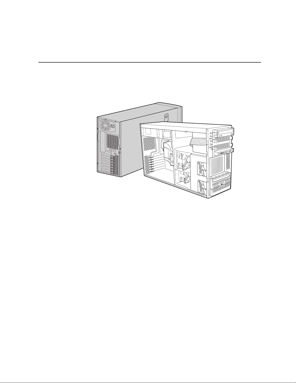
This chapter briefly describes the main features of the Intel® Server Chassis SC5400. This
chapter provides a list of the server chassis features, as well as diagrams showing the
location of important components and connections on the server chassis.
Figure 1. Intel
®
Server Chassis SC5400
AF000551
Intel® Server Chassis SC5400 User’s Guide 1
Page 20

Table 1 summarizes the features of the Intel® Server Chassis SC5400 Base SKU
Table 1. Server Chassis Features (BASE SKU)
Feature Description
Dimensions • 16.6 inches high (Pedestal: 17 inches)
• 8.6 inches wide
• 27.4 inches deep (Pedestal: 28.4 inches)
• 34.6 kilograms
Hard Drives One fixed drive bay for up to six fixed SAS or SATA drives.
Optional hot-swap drive bays:
• Six-drive SAS/SATA
• Four-drive SAS/SATA
An optional four-drive fixed drive bay is also available.
• Supports up to six drives, depending on peripheral choices.
Peripherals
Control Panel (dependent
on option selected)
LEDs and displays
(dependent on option
selected)
• Three multi-mount 5.25 peripheral bays
• Front Control Panel
®
• Intel
With Front Control Panel:
Local Control Panel (optional)
• NIC1 Activity
• NIC2 Activity
• Power / Sleep
• System Status
• System Identification
• Hard Drive Activity
Power Supply One fixed 670-W power supply with an integrated cooling fan.
Upgradable to 830-W redundant power supplies.
Fans Two fixed, non-redundant chassis fans:
• One 120-mm fan
• One 92-mm fan
Upgradable to redundant.
USB 2.0 • Two front panel USB ports with Front Control Panel
• Four back panel USB ports (depending on server board)
Video
• One rear panel video port
NOTE: The 12V 6-pin power connector is for the 150-W PCIe video
cards, which require an external 75-W power connector.
2 Intel® Server Chassis SC5400 User’s Guide
Page 21

Table 2 summarizes the features of the BRP SKU.
Table 2. Server Chassis Features (BRP SKU)
Feature Description
Dimensions • 16.6 inches high (Pedestal: 17 inches)
• 8.6 inches wide
• 27.4 inches deep (Pedestal: 28.4 inches)
• 36.2 kilograms
Hard Drives One fixed drive bay for up to six fixed SAS or SATA drives.
Optional hot swap drive bays:
• Six-drive SAS/SATA
• Four-drive SAS/SATA
An optional four-drive fixed drive bay is also available.
• Supports up to ten drives
Peripherals • Three multi-mount 5.25-inch peripheral bays
Control Panel (dependent
on option selected)
LEDs and displays
(dependent on option
selected)
• Front Control Panel
®
• Intel
With Front Control Panel:
Local Control Panel (optional)
• NIC1 Activity
• NIC2 Activity
• Power / Sleep
• System Status
• System Identification
• Hard Drive Activity
Power Supply One 830-W power supply is standard. Upgradable to 830-W
redundant power supplies
Fans Two fixed, non-redundant chassis fans:
• One 120-mm fan
• One 92-mm fan
Upgradable to redundant.
USB 2.0 • Two front panel USB ports with Front Control Panel
• Four back panel USB ports
Video
• One front panel video port (available only with Front Control
Panel)
• One rear panel video port
Intel® Server Chassis SC5400 User’s Guide 3
Page 22

Table 3 summarizes the features of the LX SKU.
Table 3. Server Chassis Features (LX SKU)
Feature Description
Dimensions • 16.6 inches high (Pedestal: 17 inches)
• 8.6 inches wide
• 27.4 inches deep (Pedestal: 28.4 inches)
• 36.2 kilograms
Hard Drives One fixed drive bay for up to six fixed SAS or SATA drives.
Optional hot-swap drive bays:
• Six-drive SAS/SATA
• Four-drive SAS/SATA
An optional four-drive fixed drive bay is also available.
• Supports up to ten drives
Peripherals • Three multi-mount 5.25-inch peripheral bays
Control Panel (dependent
on option selected)
LEDs and displays
(dependent on option
selected)
• Front Control Panel
®
• Intel
With Front Control Panel:
Local Control Panel (optional)
• NIC1 Activity
• NIC2 Activity
• Power / Sleep
• System Status
• System Identification
• Hard Drive Activity
Power Supply One redundant capable 830-W power supply module with an
Fans Four hot-swap, redundant chassis fans:
integrated cooling fan. Optional second redundant power supply
module is available.
• Two 120-mm fans
• Two 92-mm fans
USB 2.0
• Two front panel USB ports with Front Control Panel
• Four back panel USB ports
Video
• One front panel video port (available only with Standard Control
Panel)
• One rear panel video port
4 Intel® Server Chassis SC5400 User’s Guide
Page 23

Table 3 summarizes the features of the SC5400LXi SKU
Table 4. Server Chassis Features (LXi SKU)
Feature Description
Dimensions • 16.6 inches high (Pedestal: 17 inches)
• 8.6 inches wide
• 27.4 inches deep (Pedestal: 28.4 inches)
• 36.2 kilograms
Hard Drives One fixed drive bay for up to six fixed SAS or SATA drives.
Optional expanded or non-expanded hot-swap drive bays:
• Six-drive SAS/SATA
• Four-drive SAS/SATA
An optional four-drive fixed drive bay is available.
• Supports up to ten drives
Peripherals • Three multi-mount 5.25-inch peripheral bays
Control Panel (dependent
on option selected)
LEDs and displays
(dependent on option
selected)
• Front Control Panel
®
• Intel
With Front Control Panel:
Local Control Panel (optional)
• NIC1 Activity
• NIC2 Activity
• Power / Sleep
• System Status
• System Identification
• Hard Drive Activity
Power Supply One redundant capable 830-W power supply module with an
Fans Four hot-swap, redundant chassis fans:
integrated cooling fan. Optional second redundant power supply
module is available.
• Two 120-mm fans
• Two 92-mm fans
USB 2.0
• Two front panel USB ports with Front Control Panel
• Four back panel USB ports
Video
• One front panel video port (available only with Standard Control
Panel)
• One rear panel video port
Intel® Server Chassis SC5400 User’s Guide 5
Page 24
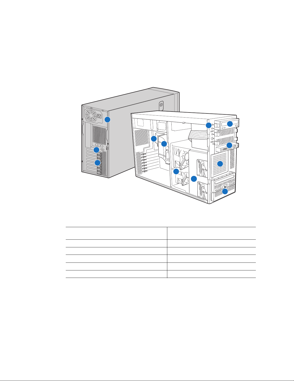
Component Identification
Internal Components
A
H
D
E
B
C
F
G
A. Fixed Power Supply G. Hard Disk Drive Cage Release
Mechanisms (2)
B. Rear Serial B Connector H. Front Panel Controls
C. PCI Add-in Card Panel I. 5.25-inch Device Bays
D. Memory Air Duct J. Front Panel USB/Serial B
E. Processor Air Duct K. Fixed Drive Cage 4-Drive (accessory)
F. Fixed Fans (2) L. Fixed Drive Cage 6-Drive
I
J
K
L
AF000511
Figure 2. Internal Component Locations
6 Intel® Server Chassis SC5400 User’s Guide
Page 25
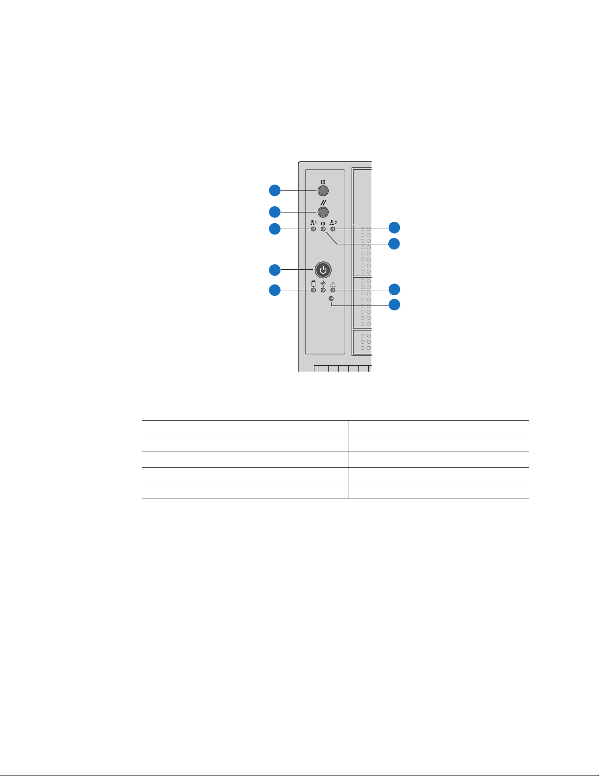
Front Control Panel
The following figure shows the features available on the Front Control Panel. The Intel®
Local Control Panel is optional.
A
B
C
F
G
D
E
H
I
TP00701
A. ID Toggle Switch F. NIC2 Activity LED (green)
B. Reset Button G. ID LED (blue)
C. NIC 1 Activity LED (green) H. Status LED (bi-color)
D. Power Button I. NMI Button
E. Hard Drive Activity LED (green)
Figure 3. Front Control Panel
Intel® Server Chassis SC5400 User’s Guide 7
Page 26

Descriptions of the front control panel LEDs are listed in the following table. See your
server documentation for functionality of buttons.
Table 5. Front Control Panel LED Descriptions
LED Name Color Condition Description
Power LED Green On Power on
Off Power off
Status Green On System ready
Blink System ready, but degraded: some CPU fault,
DIMM killed
Green/Blink
Amber
Amber On Critical alarm: critical power module failure, critical
Hard drive
activity
NIC1 activity Green On Linked
NIC2 activity Green On Linked
ID LED (rack
only)
Green Blink Hard drive activity
Blue Blink Server identification; toggled by ID button or
Blink Condition during BMC reset.
fan failure, voltage (power supply), voltage and
thermal fault
Blink Non-critical failure: redundant fan failure,
redundant power failure, non-critical power and
voltage
Off System not ready: POST error/NMI event/PCI or
terminator missing
Blink LAN activity
Off Idle
Blink LAN activity
Off Idle
software
Off Server identification; toggled by ID button or
software
8 Intel® Server Chassis SC5400 User’s Guide
Page 27
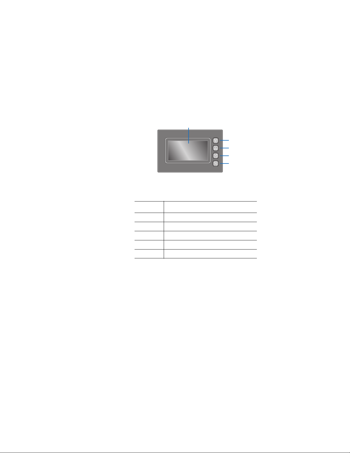
Intel® Local Control Panel
The following figure shows the features available on the Intel® Local Control Panel. The
Intel® Local Control Panel is optional.
Note: The Intel® Local Control Panel requires the installation of the Intel
Management Module. See your server board documentation to determine if this control
panel is compatible with your server board.
A
B
C
D
E
AF000955
Callout Function
A. LCD display (variable content)
B. LCD up navigation button
C. LCD down navigation button
D. LCD backup level navigation button
E. LCD command enter button
®
Remote
®
Figure 4. Intel
Intel® Server Chassis SC5400 User’s Guide 9
Local Control Panel Features
Page 28
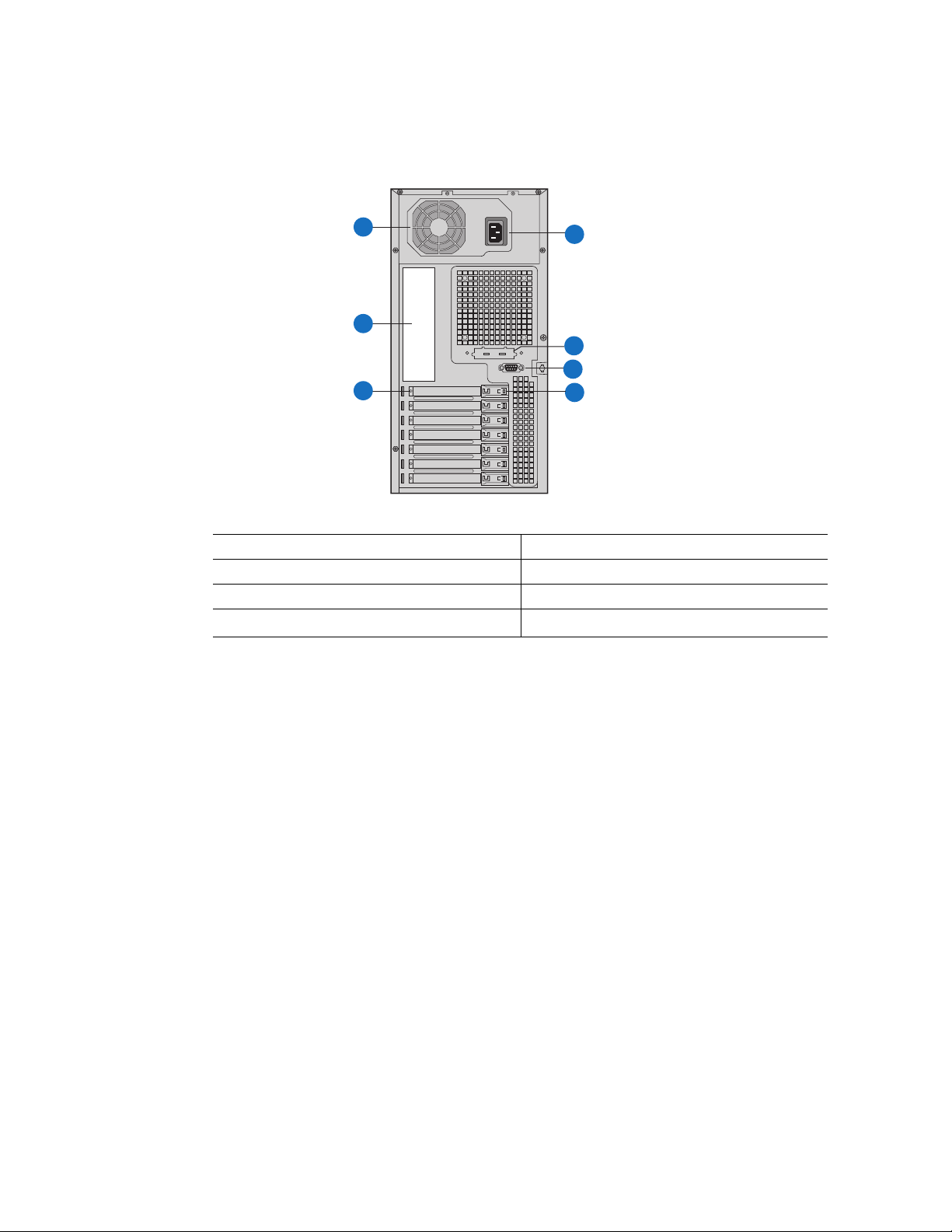
Back Panel Features
A
G
B
F
E
C
A. Fixed Power Supply B. I/O Ports
C. PCI Add-in Card Slots D. PCI Card Latch
E. Rear Serial B Connector (optional) F. Knockout
G. AC Power Connector
D
TP00526
Note: I/O connectors vary, depending on the server board installed. See your server board
documentation for port identification.
Figure 5. Server Chassis Back
10 Intel® Server Chassis SC5400 User’s Guide
Page 29
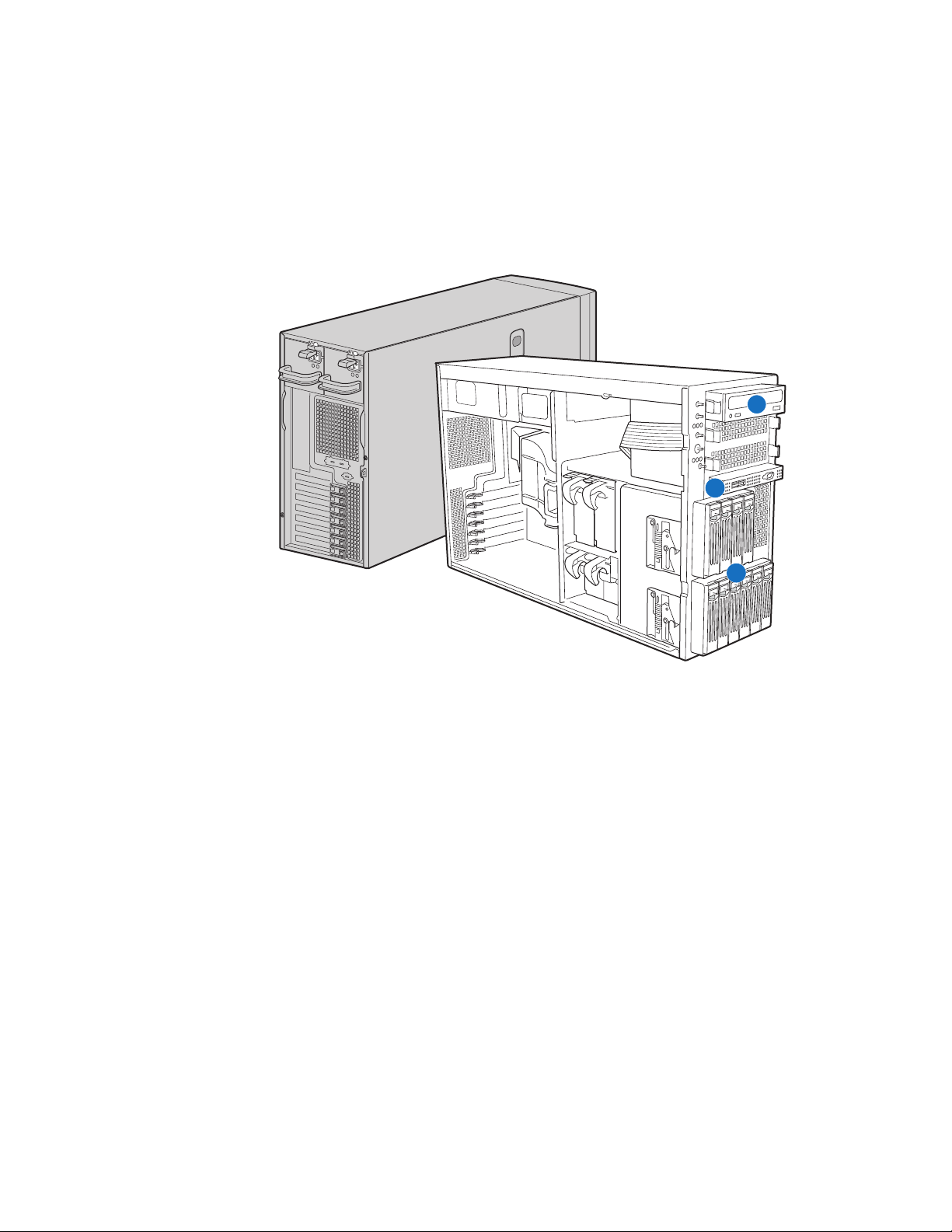
Peripheral Devices
The chassis provides locations and hardware for installing hard drives, a floppy drive, a
CD-ROM drive, or a DVD-ROM drive. The drives must be purchased separately. The
following figure shows the available options.
A
B
C
A. Slimline floppy drive / DVD-ROM drive / CD-ROM drive
B. USB ports (2)
C. Hard drive bays
Figure 6. Optional Peripherals
AF000552
Intel® Server Chassis SC5400 User’s Guide 11
Page 30

Standard and Optional Hot-swap Drive Bays
One bay supporting six cabled drives ships with the standard chassis. Optional hot swap
drive bays may replace the six-drive fixed drive bay. An optional four-drive fixed drive
bay (for cabled drives) is available. No tools are required to replace the fixed drive bays.
Optional four-drive and six-drive SAS/SATA and SCSI hot-swap drive bays are available.
For instructions on installing hard drives, see “Removing and Installing Hot Swap
Drive(s)” on page 42.
Note: Drives can consume up to 17 watts of power each. Drives must be specified to run at a
maximum ambient temperature of 45C.
The Intel
See “Additional Information and Software” on page ix for an Internet link to a list of
supported hardware.
®
Server Chassis SC5400 does not support all SAS, SATA, or SCSI hard drives.
Floppy / CD-ROM / DVD-ROM Slimline Carriers
For installation instructions on installing a floppy drive see “Installing and Removing a
Slimline USB Floppy/CD/DVD Combo Kit” on page 26. For installation instructions on
installing a CD-ROM drive or DVD-ROM drive, see “Removing and Installing a DVD or
CD-ROM Drive” on page 27.
To use one of the drives provided by Intel, use the following order codes:
• Slimline CD-ROM Drive: AXXSCD
• Slimline DVD/CDR Drive: AXXDVDCDR
• Slimline Floppy Drive: AXXCDUSBFDBRK
Note: The Intel
DVD-ROM hard drives. See “Additional Information and Software” on page ix for an
Internet link to a list of supported hardware. Intel provides accessory kits for these drives.
®
Server Chassis SC5400 does not support all slimline floppy, CD-ROM or
12 Intel® Server Chassis SC5400 User’s Guide
Page 31

Intel® Remote Management Module
The Intel® Remote Management Module is available to provide advanced system
management features.
®
For installation instructions on installing the Intel
instructions provided with the module.
Remote Management Module, see the
Note: Some server boards may not support the Intel
server board documentation to determine if this feature is compatible with your server
board.
Rack-mounted Systems
Your Intel® Server Chassis SC5400 can be mounted into a rack. Intel provides a tool-less
rail kit and a cable management arm to mount this server chassis into a rack. When
installing the chassis into a rack, Intel recommends you install systems from the bottom of
the rack to the top. In other words, install the first system in the rack into the bottom
position of the rack, the second system in the second position from the bottom, and so on.
Instructions for installing your chassis into a rack are included in the rail kit.
The order numbers are as follows:
• Tool-less Rail Kit: ARIGRACK
• Cable Management Arm: AXXRACKCARM (requires the tool-less rail kit)
®
Remote Management Module. See your
Intel® Server Chassis SC5400 User’s Guide 13
Page 32

14 Intel® Server Chassis SC5400 User’s Guide
Page 33

2 Hardware Installations and
Upgrades
Before You Begin
Before working with your server product, pay close attention to the “Safety Information”
on page iii.
This document provides instructions for adding and replacing chassis components. For
instructions on replacing components on the server board, such as the processor and
memory DIMMs, see the instructions provided with the server board.
Tools and Supplies Needed
• Phillips* (cross head) screwdriver (#1 bit and #2 bit)
• Needle nosed pliers
• Anti-static wrist strap and conductive foam pad (recommended)
System References
All references to left, right, front, top, and bottom assume the reader is facing the front of
the chassis as it would be positioned for normal operation.
Intel® Server Chassis SC5400 User’s Guide 15
Page 34

Removing and Installing the Chassis Cover
Removing the Chassis Cover
The Intel® Server Chassis SC5400 must be operated with the top cover in place to ensure
proper cooling. You will need to remove the top cover to add or replace components
inside of the platform. Before removing the top cover, power down the server and unplug
all peripheral devices and the AC power cable.
Note: A non-skid surface or a stop behind the chassis may be needed to prevent the chassis from
sliding on your work surface.
1. Observe the safety and ESD precautions at the beginning of this book. See “Safety
Information” on page iii.
2. Turn off all peripheral devices connected to the server. Turn off the server.
3. Disconnect the AC power cord.
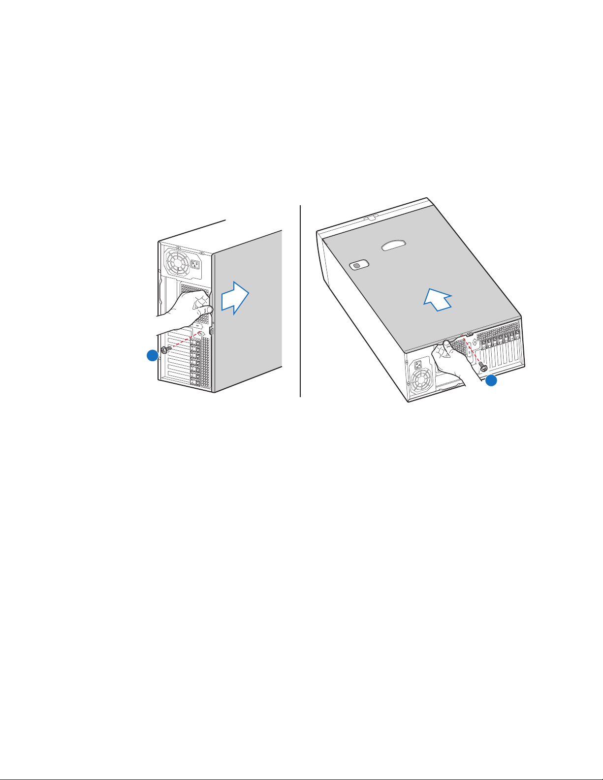
4. Remove the access cover screw if it is installed (see letter "A" in the following
figure). While holding in the blue button at the top of the chassis (see letter "B"),
slide the top cover back until it stops. Lift the cover outward to remove it.
B
B
A
A
AF000555
Figure 7. Removing the Chassis Cover
16 Intel® Server Chassis SC5400 User’s Guide
Page 35
Installing the Chassis Cover
1. Slide the chassis cover on the chassis.
2. Latch the cover securely to the chassis.
3. If the chassis will be re-shipped, secure the chassis cover to the chassis with the
access cover screw (see letter “A” in the following figure).
A
A
Figure 8. Installing the Chassis Cover
AF000572
Intel® Server Chassis SC5400 User’s Guide 17
Page 36
Removing and Installing the Front Bezel
Removing the Bezel Assembly (Pedestal Only)
Caution: Do not rotate the bezel assembly more than 40 degrees or you will damage the bezel
assembly.
Note: The bezel assembly consists of two components, a front door and a sub-bezel.
1. Observe the safety and ESD precautions at the beginning of this book.
2. Power down the server and unplug all peripheral devices and the AC power cable.
3. Remove the chassis cover. For instructions, see “Removing the Chassis Cover” on
page 16.
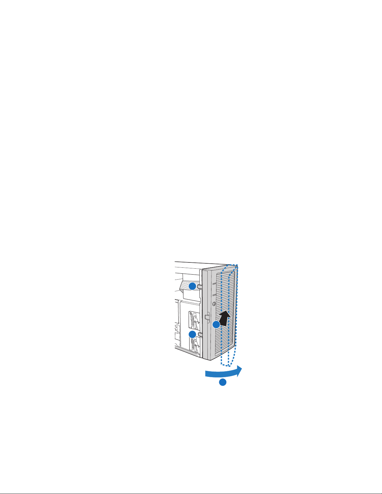
4. Release the two plastic tabs (see letter “A” in the following figure) on the left side
of the bezel assembly to disengage the tabs.
5. Rotate the bezel assembly (see letter “B”) no more than 40 degrees outward.
6. At a 40-degree angle, push the bezel assembly away from the chassis (see letter
“C”).
7. If the bezel assembly does not immediately disconnect from the chassis, tap the
left-hand side of the bezel assembly to disengage the bezel hooks on the right-hand
side of the chassis.
A
C
A
B
AF000557
Figure 9. Removing the Front Bezel
18 Intel® Server Chassis SC5400 User’s Guide
Page 37
Installing the Front Bezel (Pedestal Only)
Caution: This step applies to a pedestal configuration chassis only. For instructions on installing a
bezel in a rack-mount configuration, refer to the Rack Conversion kit Installation Guide:
®
Server Chassis SC5400.
Intel
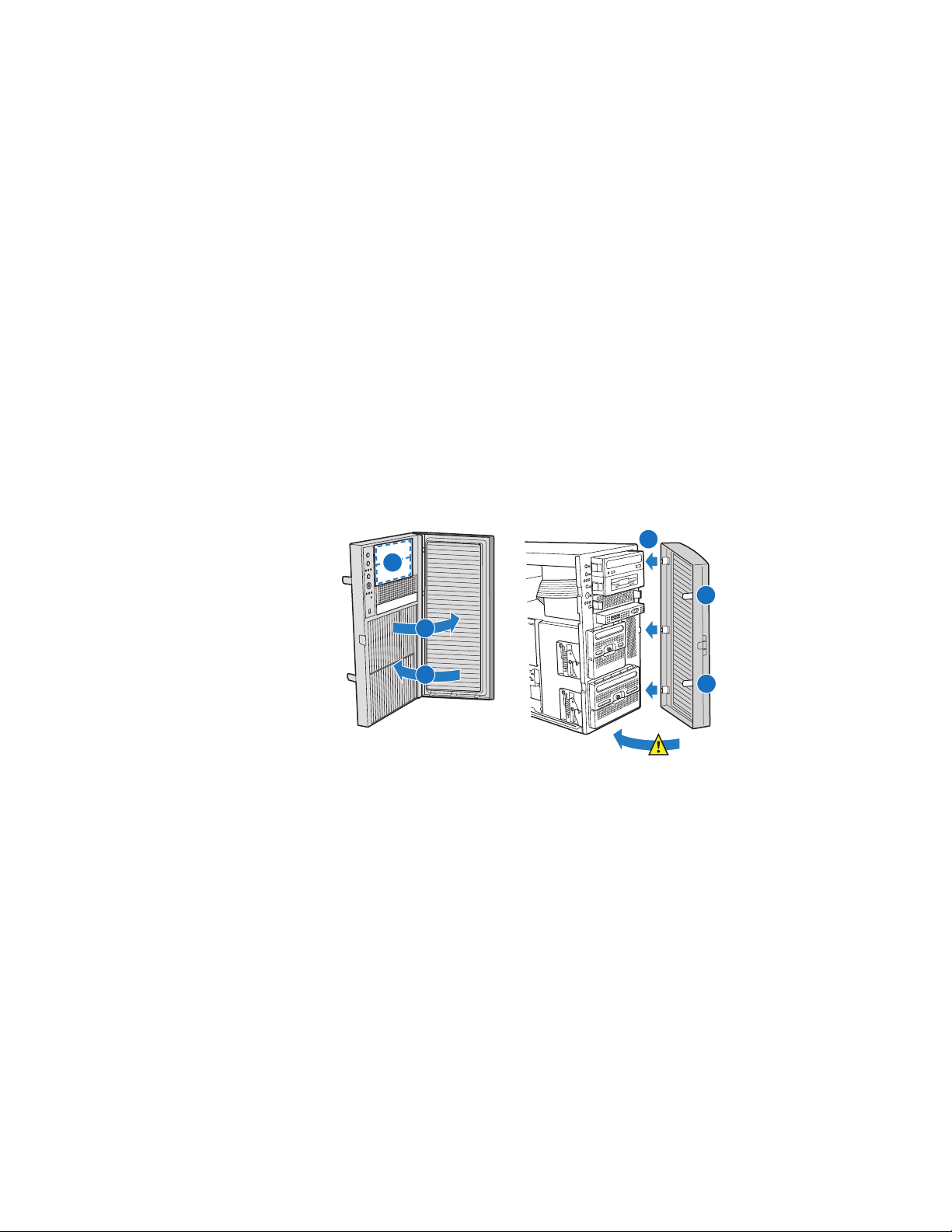
1. Open the outer bezel door of the bezel assembly (see letter “A” in the following
figure).
2. Remove the filler panels that correspond to installed devices (see letter “B”).
3. Close the outer bezel door (see letter “C”).
4. Fit the right edge of the bezel assembly against the right side of the chassis.
5. Engage the plastic bezel hooks (see letter “D”) into the raised metal slots at the
chassis edge.
6. Rotate the bezel assembly toward the chassis.
7. Latch the two plastic tabs (see letter “E”) on the left side of the bezel assembly to
the chassis.
D
B
E
A
C
Figure 10. Installing the Front Bezel
E
40° Max
AF000558
Intel® Server Chassis SC5400 User’s Guide 19
Page 38
Removing and Installing the Processor and Memory Air Ducts
Always operate your server chassis with the processor and memory air ducts in place. The
air ducts are required for proper airflow within the chassis.
For instructions on adding or replacing a processor, first remove the processor and
memory air ducts, and then see your server board user guide for instructions on processor
installations and removals. Return to these instructions to reinstall the processor and
memory air ducts after installing your processor and heat sink.
Removing the Processor and Memory Air Ducts
1. Observe the safety and ESD precautions at the beginning of this book. See “Safety
Information” on page iii.
2. Power down the server and unplug all peripheral devices and the AC power cable.
3. Remove the chassis cover. For instructions, see “Removing the Chassis Cover” on
page 16.
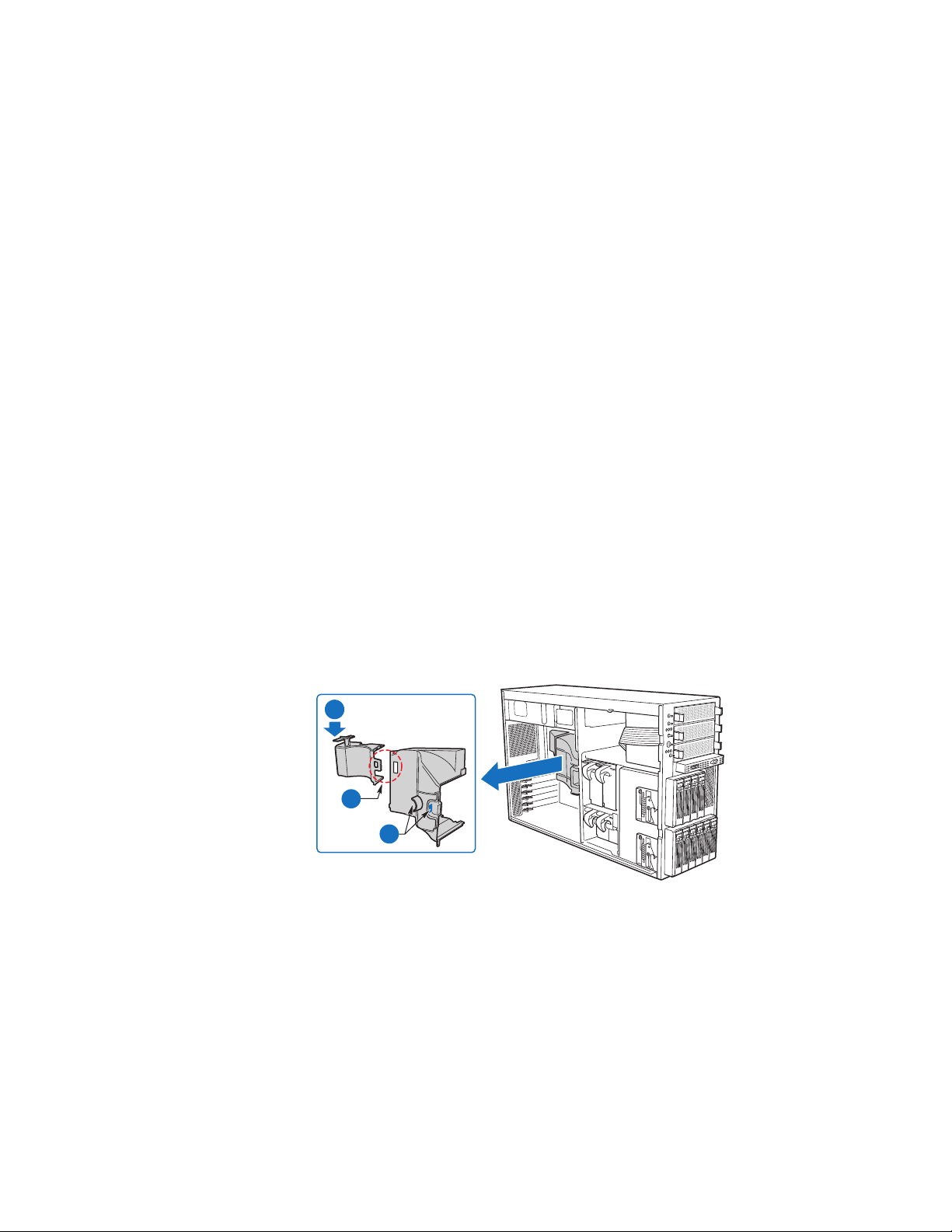
4. Press the latch on the memory air duct to disengage it from the server board (see
letter “A” in the following figure).
5. Detach the memory air duct from the processor air duct (see letter “B”).
6. Remove the processor air duct (see letter “C”).
A
B
C
AF000321
Figure 11. Removing the Processor and Memory Air Ducts
20 Intel® Server Chassis SC5400 User’s Guide
Page 39

Installing the Processor and Memory Air Ducts
1. If your system has two processors, remove the inner plastic air baffle from the
inside of the processor air duct (see letter “A” in the following figure).
Caution: This step only applies to systems with two processors. If your server board has only one
processor installed, leave the inner air baffle in place and proceed to step two.
A
AF000323
Figure 12. Removing Inner Plastic Air Baffle from Processor Air Duct
2. Install the processor air duct. Make sure the tabs on the processor air duct (see
letters “A” and “B” in the following figure) engage their matching slots on the
chassis before inserting tabs into the chassis slots.
3. Install the memory air duct next by holding the large tab-end of the memory air
duct at a downward angle and then inserting the large tab (see letter “C”) from the
underside into the matching slot on the processor air duct.
Intel® Server Chassis SC5400 User’s Guide 21
Page 40
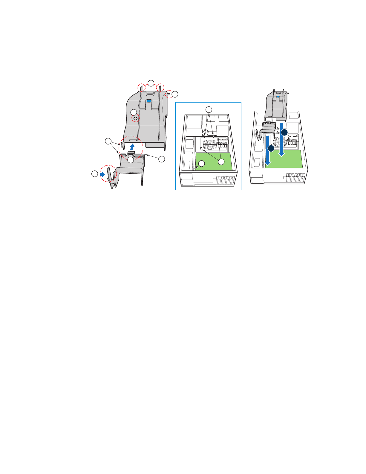
4. Rotate the memory air duct downward until the two small tabs (see letter “D”)
engage and the memory air duct latch (see letter “E”) snaps into place.
B
A
A
D
C
E
D
B
1
2
E
A
AF000325
Figure 13. Installing the Processor and Memory Air Ducts
Caution: The processor air duct interlocks with the memory air duct in two places before latching
into place.
Note: Use care to avoid pinching the cables.
22 Intel® Server Chassis SC5400 User’s Guide
Page 41
Replacing a Fixed Fan (Intel® Server Chassis SC5400Base SC5400BRP only)
Note: This procedure applies only to the Intel® Server Chassis SC5400 BASE and Intel® Server
Chassis SC5400BRP configurations. The Intel
®
Server Chassis SC5400LX and
SC5400LXi ship with hot-swap fans.
1. Observe the safety and ESD precautions at the beginning of this book.
2. Power down the server and unplug all peripheral devices and the AC power cable.
3. Remove the chassis cover. For instructions, see “Removing the Chassis Cover” on
page 16.
4. Disconnect the appropriate fan power cable from the server board.
5. Remove the 92-mm (see letter “A” in the following figure) or 120-mm (see letter
“B”) fixed fan from its snap-in bracket.
A
92-mm
Fixed Fan
B
120-mm
Fixed Fan
TP00991
Figure 14. Removing a Fixed Fan
6. Install new 92-mm or 120-mm fixed fan.
7. Connect fan power cable to the server board. See the Intel
®
server board Quick
Start User’s Guide or User Guide for appropriate connection location.
8. Re-install the chassis cover. For instructions, see “Installing the Chassis Cover” on
page 17.
9. Plug all peripheral devices and the AC power cable into the server and then power
up the server.
Intel® Server Chassis SC5400 User’s Guide 23
Page 42

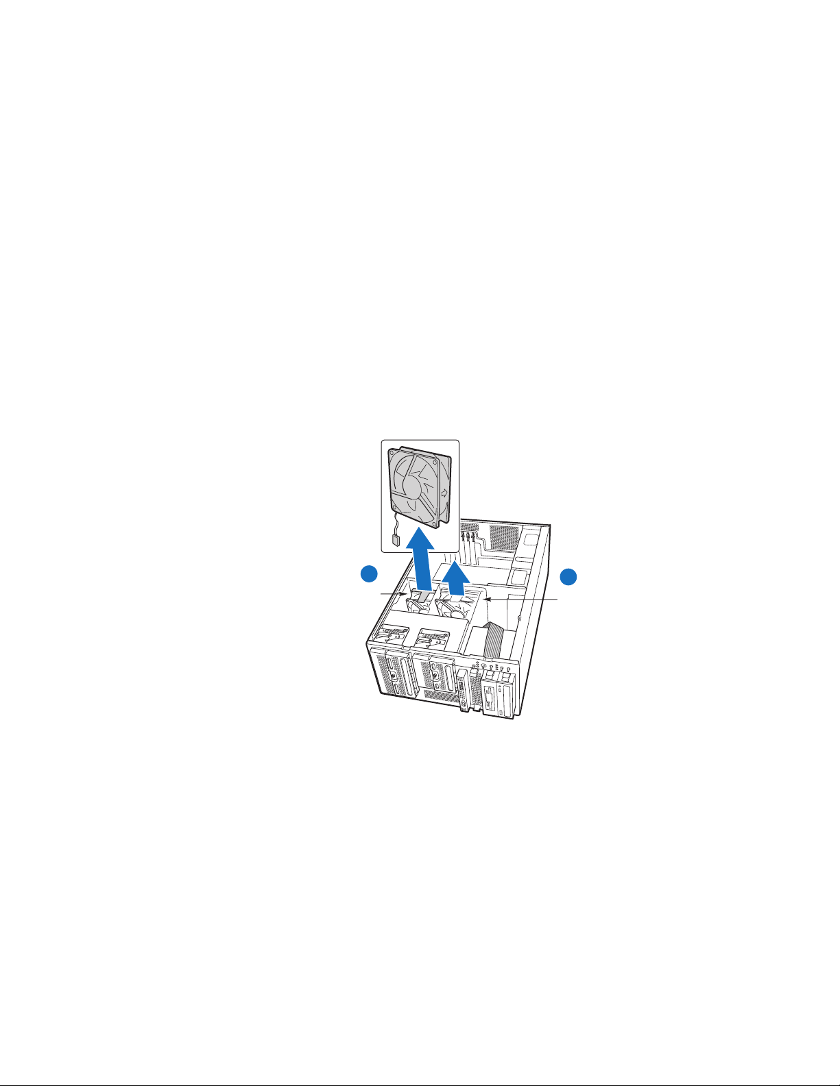
Removing and Installing Hot Swap Fans (Intel
Server Chassis SC5400LX or SC5400LXi Only)
Removing Hot Swap Fans
®
Note: This procedure applies only to the Intel® Server Chassis SC5400LX and SC5400LXi
configurations. The Intel
SC5400BRP configurations ship with fixed fans.
The hot-swap fans from the Intel
Server Chassis SC5400LX or SC5400LXi.
1. Observe the safety and ESD precautions at the beginning of this book.
2. Remove the chassis cover. For instructions, see “Removing the Chassis Cover” on
page 16.
3. Press latch on fan (see letter “A” in the following figure) and pull on handle to
remove hot swap fan from chassis.
4. Repeat previous step for removal of remaining hot swap fans.
®
Server Chassis SC5400 BASE and Intel® Server Chassis
®
Server Chassis SC5300LX cannot be used in the Intel
A
®
AF000573
Figure 15. Removing Hot Swap Fan
24 Intel® Server Chassis SC5400 User’s Guide
Page 43

Installing Hot Swap Fans
Note: This procedure applies only to the Intel® Server Chassis SC5400LX or SC5400LXi
configurations. The Intel
®
Server Chassis SC5400 BASE and Intel® Server Chassis
SC5400BRP configurations ship with fixed fans.
The hot-swap fans from the Intel
®
Server Chassis SC5300 LX cannot be used in the Intel
Server Chassis SC5400LX or SC5400LXi.
1. Observe the safety and ESD precautions at the beginning of this book.
2. Remove the chassis cover if not removed in a previous step. For instructions, see
“Removing the Chassis Cover” on page 16.
3. Insert the hot swap fan into the chassis until it latches into place.
4. Repeat previous step for insertion of remaining hot swap fans.
®
AF000574
Figure 16. Installing Hot Swap Fan
Intel® Server Chassis SC5400 User’s Guide 25
Page 44

Installing and Removing a Slimline USB Floppy/ CD/DVD Combo Kit
Installing a Slimline USB Floppy/CD/DVD Slimline Kit
Refer to the Slimline USB Floppy/CD-ROM/DVD-ROM Drive Kit Install Guide that
shipped with your slimline combo kit for installation instructions.
Removing a Slimline USB Floppy/CD/DVD Combo
1. Observe the safety and ESD precautions at the beginning of this book.
2. Power down the server and unplug all peripheral devices and the AC power cable.
3. Remove the chassis cover. For instructions, see “Removing the Chassis Cover” on
page 16.
4. Remove the front bezel if it is installed. For instructions, see “Removing and
Installing the Front Bezel” on page 18.
5. Disconnect the power and data cables to the slimline combo drive assembly.
6. Remove the combo drive/slide assembly from the chassis by pressing in on the
slide release latches (see letter “A” in the following figure). Remove the slides from
the slimline combo drive tray by pulling the slides away from the tray (see letter
“B”). A gentle pull should release the slide from the side dimple on the drive tray.
A
A
B
Figure 17. Removing Slide/Drive Assembly from Upper Device Bay
26 Intel® Server Chassis SC5400 User’s Guide
B
AF000575
Page 45

7. If not replacing with another drive, re-attach pair of slides to an EMI shield and reinsert EMI shield/slide assembly into chassis for proper airflow.
AF000605
Figure 18. Re-inserting Empty EMI Shield/Slide Assembly into Chassis
8. Install the front bezel. For instructions, see “Removing and Installing the Front
Bezel” on page 18.
9. Install the chassis cover. For instructions, see “Installing the Chassis Cover” on
page 17.
10. Plug all peripheral devices and the AC power cable into the server.
11. Power up the server.
Removing and Installing a DVD or CD-ROM Drive
Removing a DVD or CD-ROM Drive
1. Observe the safety and ESD precautions at the beginning of this book.
2. Power down the server and unplug all peripheral devices and the AC power cable.
3. Remove the chassis cover. For instructions, see “Removing the Chassis Cover” on
page 16.
4. Remove the front bezel if it is installed. For instructions, see “Removing and
Installing the Front Bezel” on page 18.
5. Disconnect the power and data cables to the DVD/CD-ROM drive.
Intel® Server Chassis SC5400 User’s Guide 27
Page 46

6. Remove the DVD/CD-ROM drive/slide assembly from the chassis by pressing in
on the slide release latches (see letter “A” in the following figure). Remove the
slides from the DVD or CD-ROM drive by pulling the slides away from the drive
(see letter “B”). A gentle pull should release the slide from the side dimple on the
drive.
A
A
B
B
AF000575
7. If not replacing with another drive, re-attach pair of slides to an EMI shield and reinsert EMI shield/slide assembly into chassis for proper airflow.
AF000605
Figure 19. Re-inserting Empty EMI Shield/Slide Assembly into Chassis
8. Install the front bezel. For instructions, see “Removing and Installing the Front
Bezel” on page 18.
9. Install the chassis cover. For instructions, see “Installing the Chassis Cover” on
page 17.
10. Plug all peripheral devices and the AC power cable into the server.
11. Power up the server.
28 Intel® Server Chassis SC5400 User’s Guide
Page 47

Installing a DVD or CD-ROM Drive
1. Observe the safety and ESD precautions at the beginning of this book.
2. Power down the server and unplug all peripheral devices and the AC power cable.
3. Remove the chassis cover. For instructions, see “Removing the Chassis Cover” on
page 16.
4. Remove the front bezel if it is installed. For instructions, see “Removing and
Installing the Front Bezel” on page 18.
5. Remove an EMI shield/slide assembly from the upper device bay by pressing the
two slide assembly latches inward (see letter “A” in the following figure). Remove
the slides from the EMI shield by pulling the slides away from the EMI shield to
release them from the EMI shield (see letter “B”).
A
A
B
B
AF000945
Figure 20. Removing EMI Shield/Slide Assembly from Upper Device Bay
6. Attach slides to the DVD or CD-ROM drive by pressing the slides firmly into the
side dimples on the DVD or CD-ROM drive.
AF000576
Figure 21. Attaching Slides to a DVD or CD-ROM Drive
Intel® Server Chassis SC5400 User’s Guide 29
Page 48

7. Insert the drive/slide assembly into the upper device bay until the slides lock into
place.
8. Connect power and data cables.
9. Install the front bezel. For instructions, see “Removing and Installing the Front
Bezel” on page 18.
10. Install the chassis cover. For instructions, see “Installing the Chassis Cover” on
page 17.
11. Plug all peripheral devices and the AC power cable into the server.
12. Power up the server.
Removing and Installing Fixed Hard Drive(s)
Removing Fixed Hard Drive(s)
1. Observe the safety and ESD precautions at the beginning of this book.
2. Power down the server and unplug all peripheral devices and the AC power cable.
3. Remove the chassis cover. For instructions, see “Removing the Chassis Cover” on
page 16.
4. Remove the front bezel if it is installed. For instructions, see “Removing and
Installing the Front Bezel” on page 18.
5. Push the blue plastic release mechanism upward to release the fixed drive cage (see
letter “A” in the following figure).
6. Remove power and data cables from the hard drive connectors.
7. Pull the drive cage out about two inches (see letter “B”) so that it is partially
exposed from the drive bay slot in the chassis. Partially exposing the drive cage will
make it easier to open the upper door of the drive cage.
Note: As an alternative, you may also fully remove the drive cage from its drive bay
slot in the chassis. Take care, however, to position the drive cage horizontally
before opening the drive cage doors or the drive rails will spill out.
30 Intel® Server Chassis SC5400 User’s Guide
Page 49
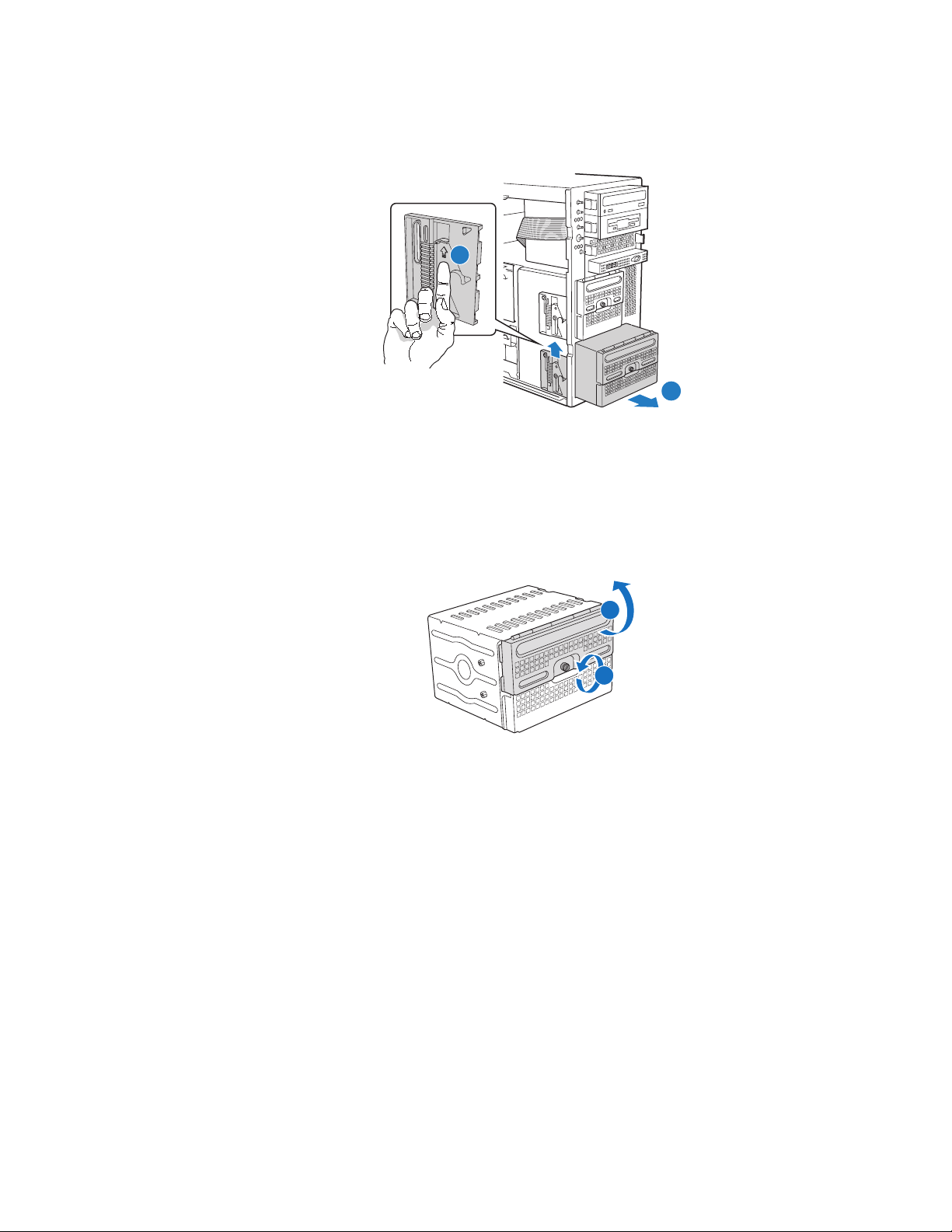
Figure 22. Removing Six-drive Fixed Drive Cage from Chassis
A
B
TP00906
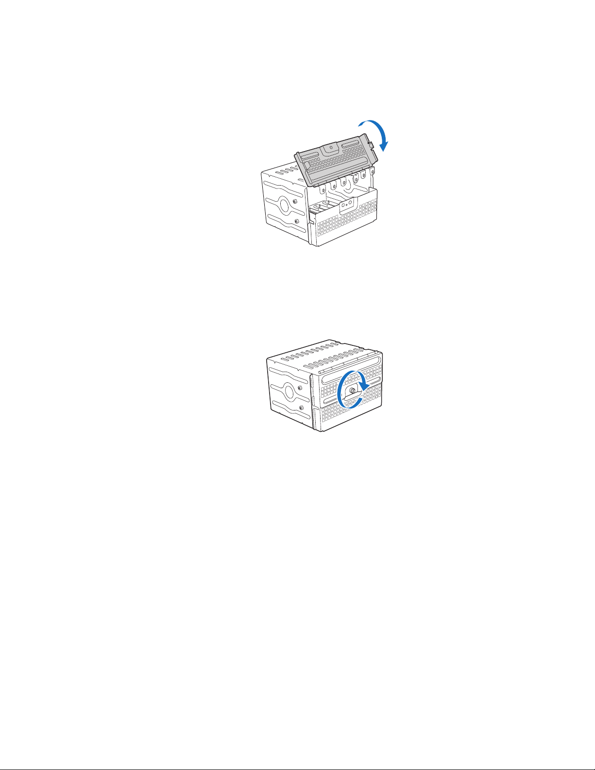
8. Loosen the thumb screw (see letter “A” in the following figure). Open the upper
door of the drive cage (see letter “B”).
B
A
AF000579
Figure 23. Unlocking and Opening Upper Door of Fixed Drive Cage
Intel® Server Chassis SC5400 User’s Guide 31
Page 50
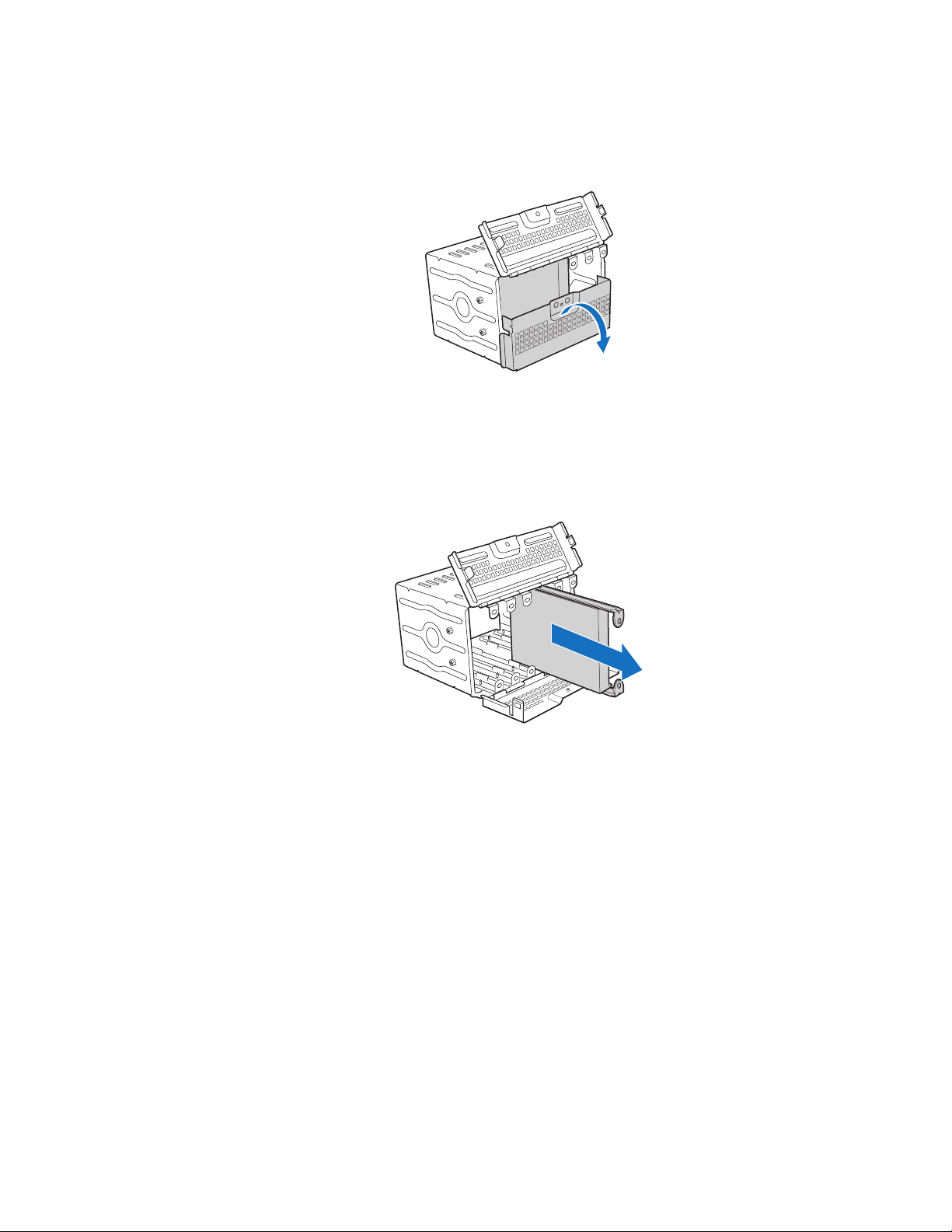
9. Open the lower door.
AF000946
Figure 24. Opening Lower Door of Fixed Drive Cage
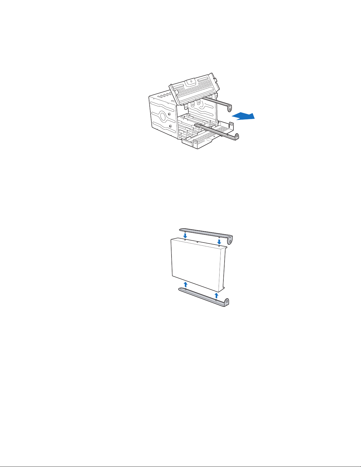
10. Remove the drive/slide assembly from the drive cage.
AF000588
Figure 25. Removing Drive/Slide Assembly from Drive Cage
32 Intel® Server Chassis SC5400 User’s Guide
Page 51
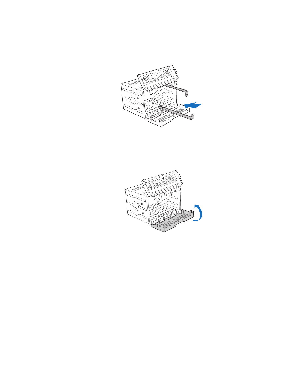
11. Remove the device slides from hard drive. If not replacing hard drive, insert empty
device slides into drive cage.
AF000947
Figure 26. Inserting Empty Device Slides into Drive Cage
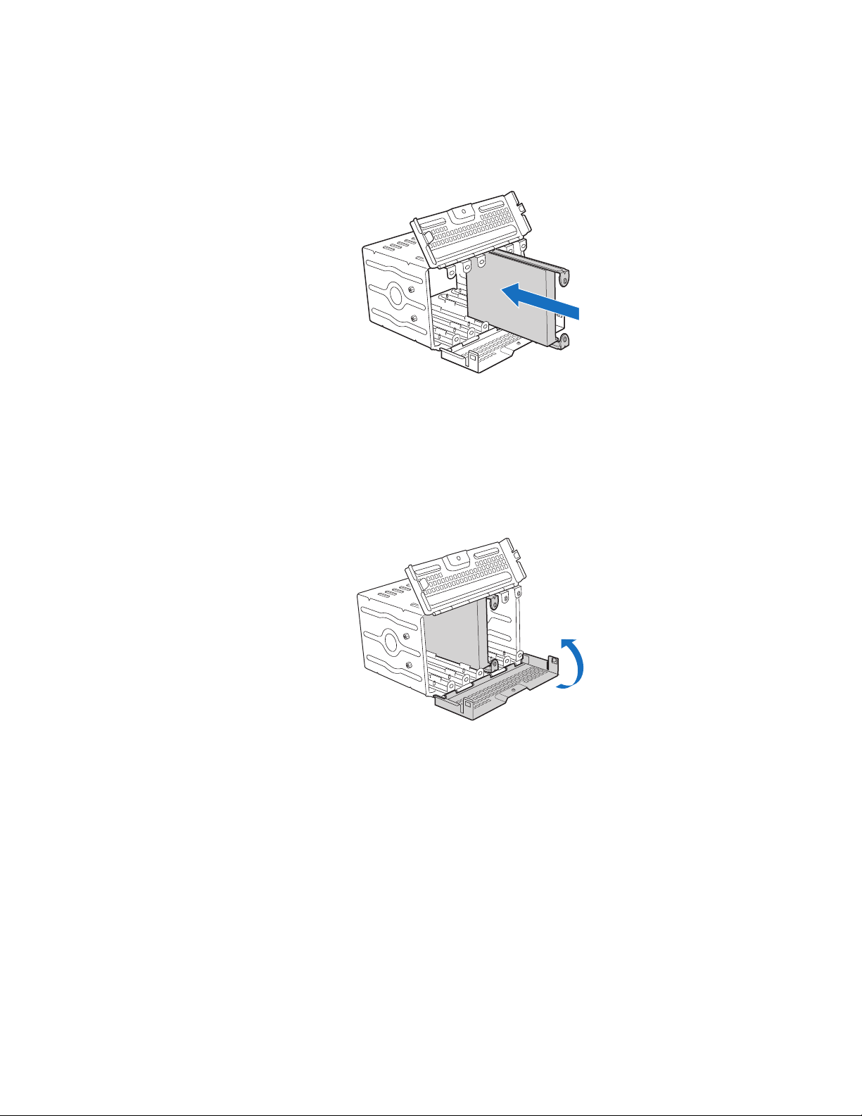
12. Close the lower door of drive cage.
AF000948
Figure 27. Closing Lower Door of Fixed Drive Cage
Intel® Server Chassis SC5400 User’s Guide 33
Page 52
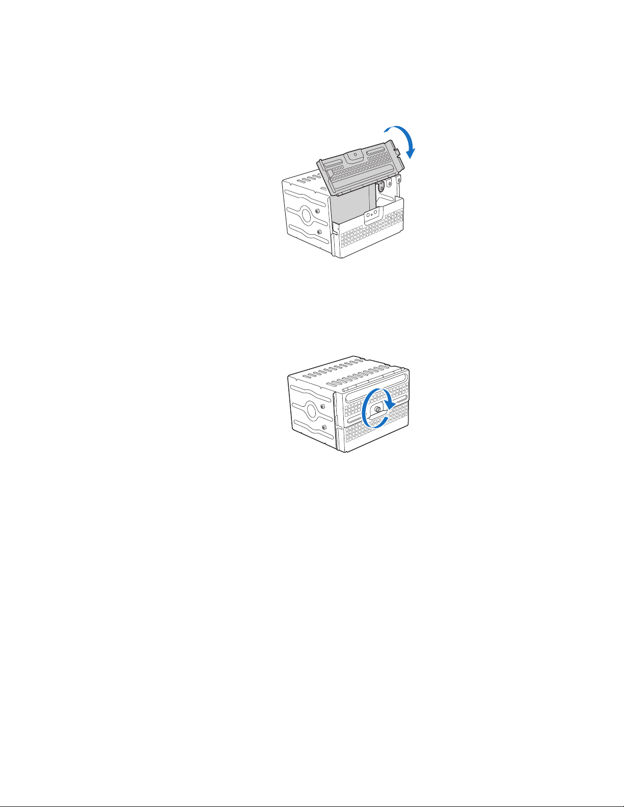
13. Close the upper door.
Figure 28. Closing Upper Door of Fixed Drive Cage
14. Tighten the captive screw.
AF000949
AF000586
Figure 29. Tightening Thumb Screw
15. Reinstall fixed hard drive into chassis.
16. If other hard drives remain in the drive cage, reconnect power and data cables.
17. Install the front bezel. For instructions, see “Removing and Installing the Front
Bezel” on page 18.
18. Install the chassis cover. For instructions, see “Installing the Chassis Cover” on
page 17.
19. Plug all peripheral devices and the AC power cable into the server.
20. Power up the server.
34 Intel® Server Chassis SC5400 User’s Guide
Page 53

Installing Fixed Hard Drive(s)
A
B
TP00906
1. Observe the safety and ESD precautions at the beginning of this book.
2. Power down the server and unplug all peripheral devices and the AC power cable.
3. Remove the chassis cover. For instructions, see “Removing the Chassis Cover” on
page 16.
4. Remove the front bezel if it is installed. For instructions, see “Removing and
Installing the Front Bezel” on page 18.
5. Push the blue plastic release mechanism upward to release the fixed drive cage (see
letter “A” in the following figure). Pull the drive cage out about two inches (see
letter “B”) so that it is partially exposed from the drive bay slot in the chassis.
Partially exposing the drive cage will make it easier to open the upper door of the
drive cage.
Note: As an alternative, you may also fully remove the drive cage from its drive bay
slot in the chassis. Take care, however, to position the drive cage horizontally
before opening the drive cage doors or the drive rails will spill out.
Figure 30. Removing Six-drive Fixed Drive Cage from Chassis
Intel® Server Chassis SC5400 User’s Guide 35
Page 54

6. Loosen the captive screw (see letter “A” in the following figure). Open the upper
door (see letter “B”).
B
A
AF000579
Figure 31. Unlocking and Opening Upper Door of Fixed Drive Cage
7. Open the lower door.
AF000580
Figure 32. Opening Lower Door of Fixed Drive Cage
36 Intel® Server Chassis SC5400 User’s Guide
Page 55
8. Remove a pair of device slides from the drive cage.
AF000581
Figure 33. Removing Slides from Drive Cage
9. Attach the device slides to the hard drive. This is a tool-less operation. Insert pins
on device slides into mounting holes on hard drive. Press firmly to secure device
slides to hard drive. Ensure that the metal tabs on the device slides are facing the
front of the hard drive and facing towards each other.
AF000582
Figure 34. Attaching Device Slides to Hard Drive
Intel® Server Chassis SC5400 User’s Guide 37
Page 56
10. Insert the drive/slide assembly into the drive cage. Make sure the cable connector
end of the hard drive faces towards the rear of the drive cage.
AF000583
Figure 35. Inserting Drive/Slide Assembly into Drive Cage
11. Repeat above steps for installation of additional hard drives into the drive cage.
12. Close the lower door of drive cage.
.
AF000584
Figure 36. Closing Lower Door of Fixed Drive Cage
38 Intel® Server Chassis SC5400 User’s Guide
Page 57
13. Close the upper door of drive cage.
Figure 37. Closing Upper Door of Fixed Drive Cage
14. Tighten the captive screw.
AF000585
AF000586
Figure 38. Tightening Captive Screw
15. Re-install fixed drive cage into chassis.
16. Connect power and data cables to connectors on hard drive(s).
17. Install the front bezel. For instructions, see “Removing and Installing the Front
Bezel” on page 18.
18. Install the chassis cover. For instructions, see “Installing the Chassis Cover” on
page 17.
19. Plug all peripheral devices and the AC power cable into the server.
20. Power up the server.
Intel® Server Chassis SC5400 User’s Guide 39
Page 58

Routing Power Cables to Fixed Drives
Power Cable Routing
Chassis Primary Side View
To Server Board
Cable
Slot
To 4-Drive
To 6-Drive
Cage
PCI Add-in
card retainer
detail
P2
To Upper Device Bay
Cage
AF000510
Figure 39. Routing Power Cables to Fixed Drives
Route longest power cables to the 6-drive bay and shorter cables to the 4-drive bay and
upper device bay.
Power Cable Routing Guidelines:
• P3, P4 and P5 power cables route to removable drives.
• P6, P7, P8, P9, P10 and P11 power cables (standard SAS/SATA); route as
appropriate.
• P12 and P13 power cables (SATA); route as appropriate.
40 Intel® Server Chassis SC5400 User’s Guide
Page 59

Routing Data Cables to Fixed Drives
Note: Front panel, USB and one IDE cable are pre-routed by the factory. SAS or SATA cables
are supplied with the server board and hot-swap drive accessory kits. No cables are
supplied with the fixed drive bay kit.
• Route SAS/SATA data cables through the chassis openings located near the bottom
of the drive cage.
• Connect data cables to the respective fixed drive and to the appropriate connector on
the server board.
SAS/SATA Cable Routing
Chassis Primary Side View
To 4-Drive
IDE/USB/Front Panel Cables
4/6 Drive
Bay Cables
Chassis Primary Side View
Cage
SAS/SATA
To 6-Drive Cage
AF000509
Figure 40. Routing SAS/SATA Data Cables
Intel® Server Chassis SC5400 User’s Guide 41
Page 60

Removing and Installing Hot Swap Drive(s)
Removing Hot Swap Drive(s)
1. Rotate the black lever downwards to unlatch the drive carrier. With the black lever
open, remove the drive carrier from the drive cage.
AF000593
Figure 41. Releasing Drive Carrier from Hot Swap Cage
2. Remove the four screws securing the hard drive to the drive carrier. Remove the
hard drive from the drive carrier.
AF000595
Figure 42. Removing Hard Drive from Drive Carrier
42 Intel® Server Chassis SC5400 User’s Guide
Page 61

3. If not replacing with another hard drive, re-install the plastic air baffle into the
empty drive carrier. Secure the plastic air baffle to the drive carrier using the four
screws that were formerly attached to the hard drive.
Note: Plastic air baffles are necessary in all empty drive carriers to ensure proper
airflow within the chassis.
AF000950
Figure 43. Installing Plastic Air Baffle in Drive Carrier
4. With the black lever open, insert the drive carrier into the drive cage. Once inserted,
rotate the black lever upwards to latch the drive carrier into position.
AF000592
Figure 44. Inserting Drive Carrier into Hot Swap Cage
Intel® Server Chassis SC5400 User’s Guide 43
Page 62

Installing Hot Swap Drive(s)
1. Press in on the green latch (see letter “A” in the following figure) at the end of the
drive carrier to disengage it from the hot swap drive cage.
2. Pull out on the black lever (see letter “B”) to fully open the drive carrier. When the
lever reaches a fully opened position, it will push the drive carrier out from the hot
swap drive cage. Slide the drive carrier out of the drive cage (see letter “C”).
A
B
C
AF000589
Figure 45. Removing Drive Carrier from Hot Swap Cage
3. Remove the four screws that secure the plastic air baffle to the drive carrier.
Remove the plastic air baffle.
AF000590
Figure 46. Removing Plastic Air Baffle
4. Secure the hard drive to the drive carrier using the four screws that were formerly
attached to the plastic air baffle. Ensure that the connector end of the hard drive is
facing the back of the drive carrier. The label side of the hard drive should be facing
up in the drive carrier.
44 Intel® Server Chassis SC5400 User’s Guide
Page 63

AF000591
Figure 47. Securing Hard Drive to Drive Carrier
5. With the black lever open, insert the drive carrier into the drive cage. Once inserted,
rotate the black lever upwards to latch the drive carrier into position.
AF000592
Figure 48. Inserting Drive Carrier into Hot Swap Cage
Removing and Installing PCI Add-in Board(s)
Removing PCI Add-in Board(s)
Caution: When removing a full-length add-in card, you must pull back the latch on the plastic card
guide at the front of the chassis to release the card from the card guide.
1. Observe the safety and ESD precautions at the beginning of this book.
2. Power down the server and unplug all peripheral devices and the AC power cable.
3. Remove the chassis cover. For instructions, see “Removing the Chassis Cover” on
page 16.
4. Remove the front bezel if it is installed. For instructions, see “Removing and
Installing the Front Bezel” on page 18.
5. Remove any cables attached to the add-in card, if necessary.
6. Remove the PCI add-in card retainer. Press in on the two plastic tabs (see letter “A”
in the following figure) to release the PCI add-in card retainer from the chassis.
Intel® Server Chassis SC5400 User’s Guide 45
Page 64
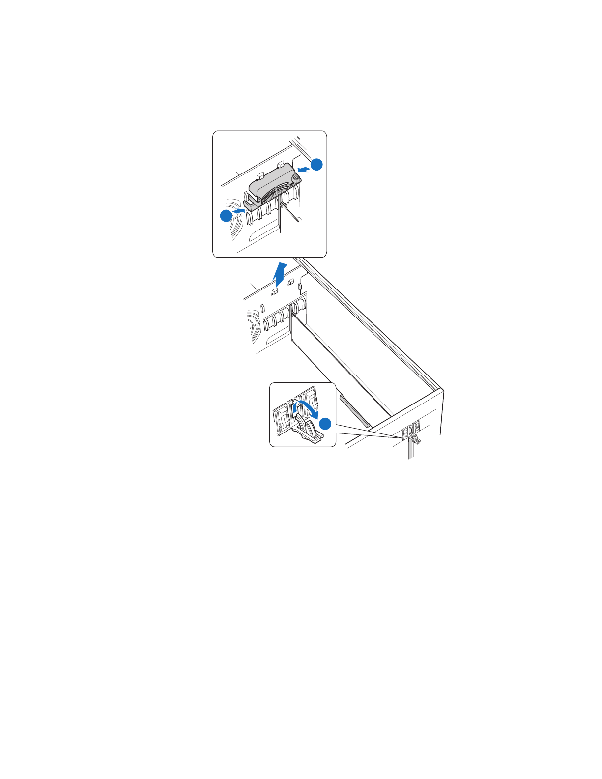
Open the back panel PCI add-in card retention device (see letter “B”) by pressing
open from the inside of the chassis.
A
A
B
AF000600
Figure 49. Preparing Chassis for Removal of PCI Add-in Board
46 Intel® Server Chassis SC5400 User’s Guide
Page 65

7. Firmly grab the PCI add-in board by its top edge or outer corners and remove from
the expansion slot on the server board. Place the removed PCI add-in board in an
anti-static protective wrapper. Close the back panel PCI add-in card retention
device.
8. Remove additional PCI add-in boards as necessary. When done, reinstall the PCI
add-in card retainer and close the PCI add-in card retention device(s).
9. Install the front bezel. For instructions, see “Removing and Installing the Front
Bezel” on page 18.
10. Install the chassis cover. For instructions, see “Installing the Chassis Cover” on
page 17.
11. Plug all peripheral devices and the AC power cable into the server.
12. Power up the server.
Installing PCI Add-in Board(s)
Caution: You may want to install an operating system before installing any add-in boards.
Do not overload the server board by installing add-in boards that draw excessive current.
Add-in boards can be extremely sensitive to ESD and always require careful handling.
After removing the board from its protective wrapper, place it component side up on a
grounded, static-free surface. Do not slide the board over any surface.
When removing a full-length add-in card, you must pull back on the latch on the plastic
card guide at the front of the chassis to release the card from the card guide.
1. Observe the safety and ESD precautions at the beginning of this book.
2. Power down the server and unplug all peripheral devices and the AC power cable.
3. Remove the chassis cover. For instructions, see “Removing the Chassis Cover” on
page 16.
4. Remove the front bezel if it is installed. For instructions, see “Removing and
Installing the Front Bezel” on page 18.
Intel® Server Chassis SC5400 User’s Guide 47
Page 66
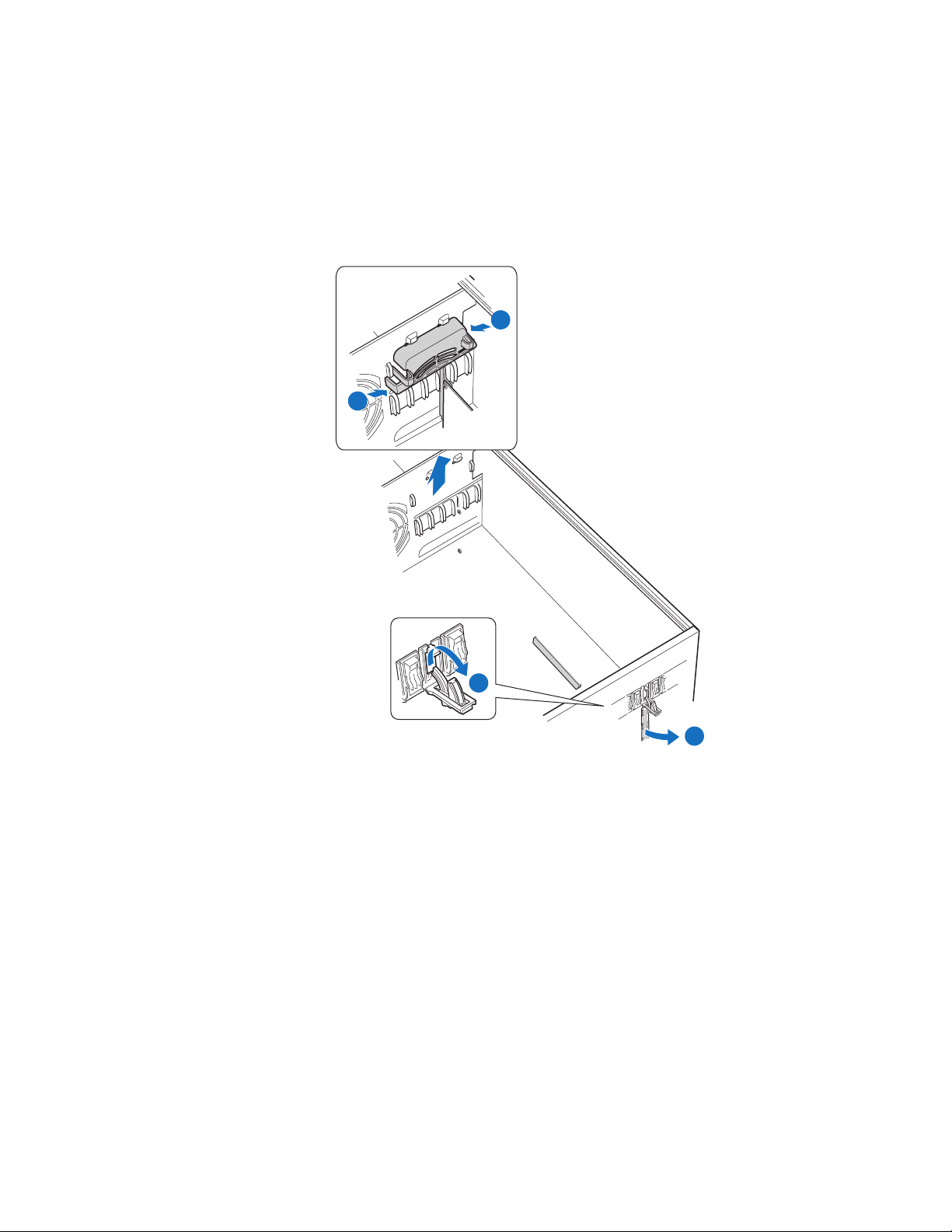
5. Press in on the two plastic tabs (see letter “A” in the following figure) and remove
the PCI add-in card retainer. Open the back panel PCI add-in card retention device
(see letter “B”) by pressing open from the inside of the chassis. Remove the PCI
slot shield (see letter “C”), if it has not already been removed, by pushing the shield
out from the inside of the chassis
A
A
B
AF000954
C
Figure 50. Preparing Chassis for Addition of PCI Add-in Board
6. Remove the PCI add-in board from its protective wrapper. Be careful not to touch
the components or gold edge connectors. Place the add-in board on an anti-static
surface. Record the type and serial number of the add-in board in your equipment
log. Set the jumpers or switches on the board according to the manufacturer’s
instructions.
48 Intel® Server Chassis SC5400 User’s Guide
Page 67
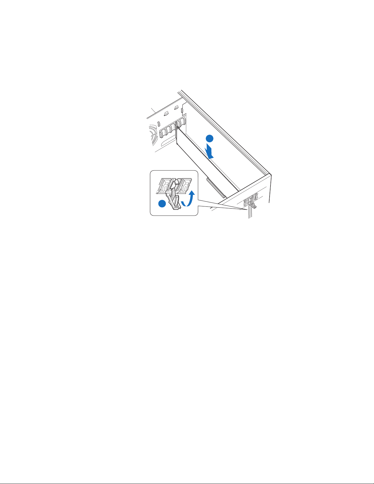
7. Hold the PCI add-in board by its top edge or upper corners. Firmly press the add-in
board into an expansion slot on the server board (see letter “A” in the following
figure). Close the back panel PCI add-in card retention device (see letter “B”).
A
B
AF000599
Figure 51. Installing Add-in Board
8. Repeat steps 2-10 until all the PCI add-in cards are installed.
Intel® Server Chassis SC5400 User’s Guide 49
Page 68
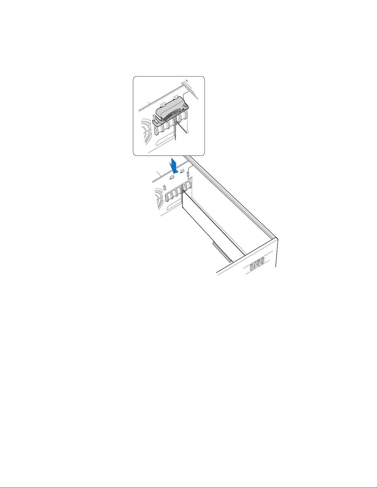
9. Reinstall the PCI Add-in Card Retainer.
AF000600
Figure 52. Reinstalling PCI Add-in Card Retainer
10. Attach cables if necessary.
11. Install the front bezel. For instructions, see “Removing and Installing the Front
Bezel” on page 18.
12. Install the chassis cover. For instructions, see “Installing the Chassis Cover” on
page 17.
13. Plug all peripheral devices and the AC power cable into the server.
14. Power up the server.
50 Intel® Server Chassis SC5400 User’s Guide
Page 69
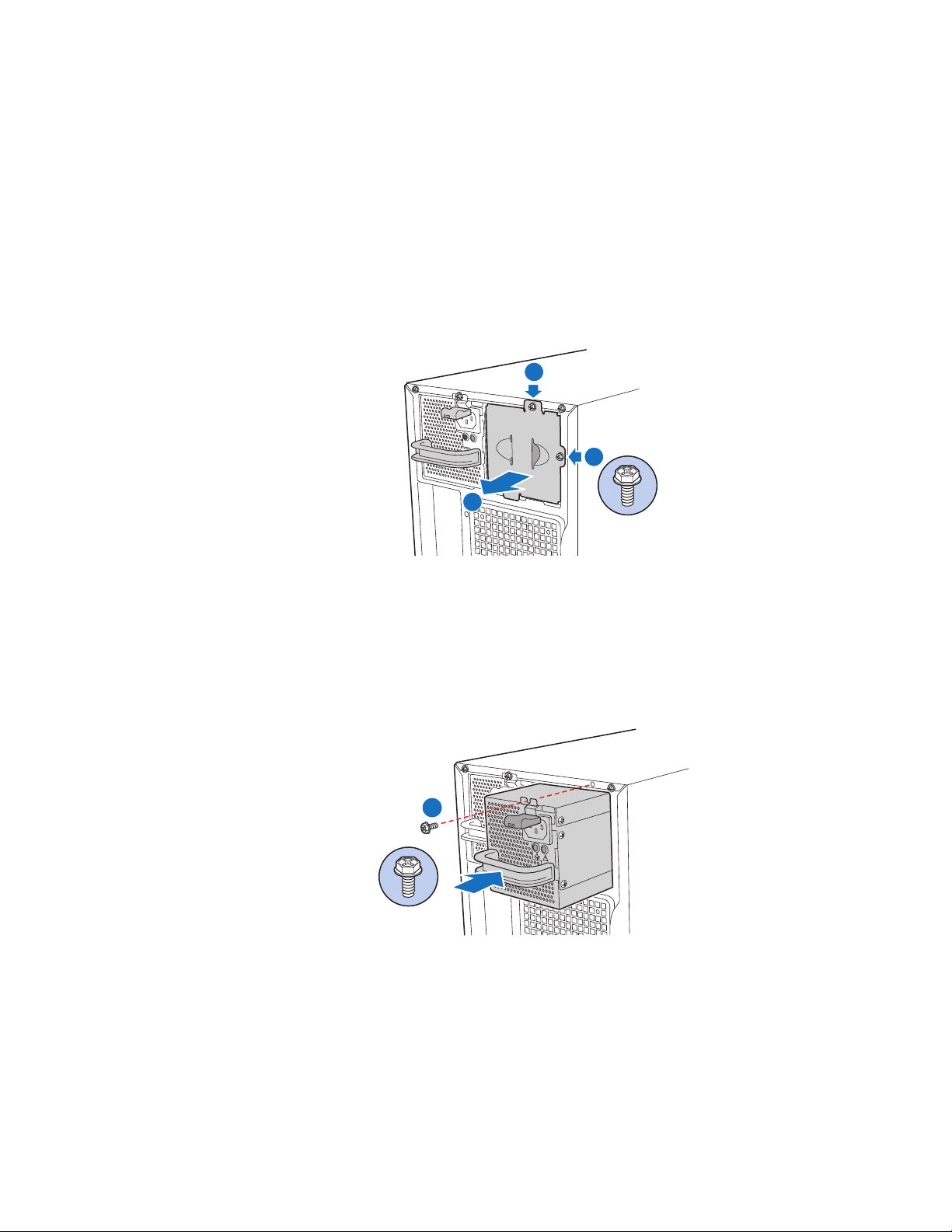
Installing Additional Hot Swap Power Supply Module
Caution: This step only applies to a chassis with redundant power supply capability. Do not
perform this step if your chassis has a fixed power supply.
1. Remove screws (see letter “A” in the following figure). Remove the power supply
filler panel (see letter “B”).
A
A
B
AF000602
Figure 53. Removing Power Supply Filler Panel
2. Insert the power supply module until it clicks into place. Secure with screw (see
letter “A” in the following figure) if shipping chassis to another location.
A
AF000603
Figure 54. Installing Additional Hot Swap Power Supply Module
Intel® Server Chassis SC5400 User’s Guide 51
Page 70
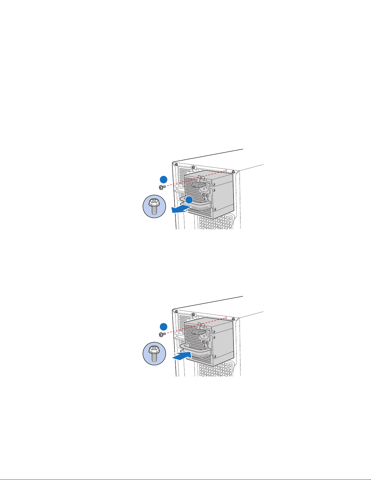
Replacing a Hot Swap Power Supply
Warnin g : Hazardous voltage, current, and energy levels are present inside the power supply. There
are no user-serviceable parts inside it; servicing should be done by technically qualified
personnel.
1. Remove the power cable from the defective hot swap power supply.
2. If present, remove shipping screw securing defective hot swap power supply to
chassis (see letter “A” in the following figure). Press on green latch (see letter “B”)
while pulling on handle to remove power supply from chassis.
A
B
AF000956
Figure 55. Removing Hot Swap Power Supply from Chassis
3. Insert new hot swap power supply into chassis. Replace shipping screw (see letter
“A” in the following figure) if shipping chassis to another location.
A
AF000603
Figure 56. Installing Hot Swap Power Supply into Chassis
4. Connect power cable to replaced power supply.
52 Intel® Server Chassis SC5400 User’s Guide
Page 71
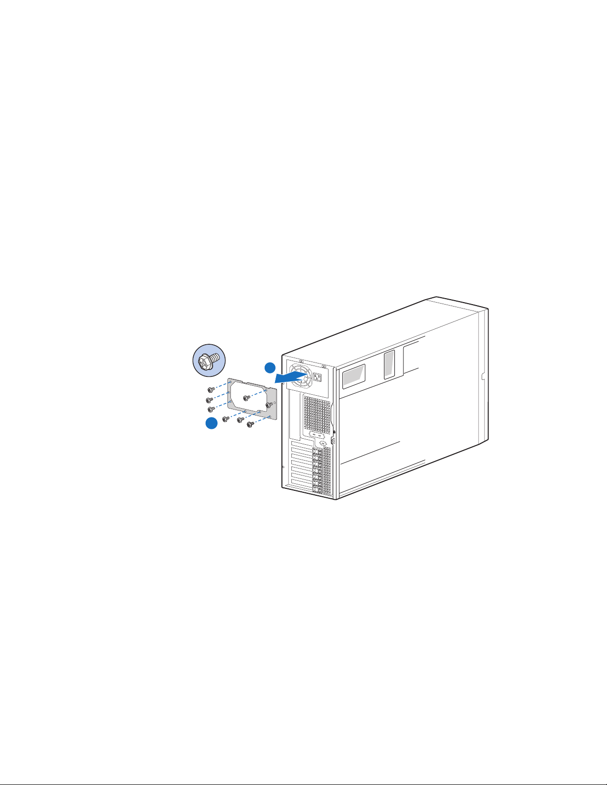
Replacing a Fixed Power Supply
Warnin g : Hazardous voltage, current, and energy levels are present inside the power supply. There
are no user-serviceable parts inside it; servicing should be done by technically qualified
personnel.
1. Observe the safety and ESD precautions at the beginning of this book.
2. Power down the server and unplug all peripheral devices and the AC power cable.
3. Remove the chassis cover. For instructions, see “Removing the Chassis Cover” on
page 16.
4. Disconnect all internal power cables from chassis components and server board.
5. Remove the eight screws securing the fixed power supply shield to the chassis (see
letter “A” in the following figure). Remove the fixed power supply (see letter “B”).
B
A
AF000957
Figure 57. Removing Fixed Power Supply
6. Insert new fixed power supply.
7. Secure the fixed power supply shield to the chassis with the eight screws.
8. Connect the P1, P14, and P16 cables to the server board. See the Intel
®
server
board Quick Start User’s Guide or User Guide for connection locations.
9. Reconnect power cables to other chassis components as appropriate.
10. Install the chassis cover. For instructions, see “Installing the Chassis Cover” on
page 17.
11. Plug all peripheral devices and the AC power cable into the server.
12. Power up the server.
Intel® Server Chassis SC5400 User’s Guide 53
Page 72
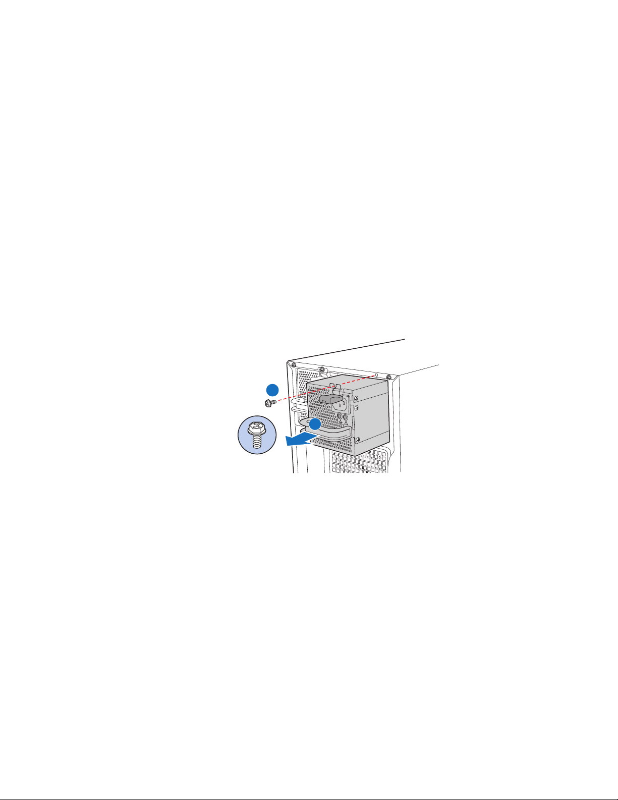
Replacing the Power Distribution Board
Warnin g : Hazardous voltage, current, and energy levels are present inside the power supply. There
are no user-serviceable parts inside it; servicing should be done by technically qualified
personnel.
1. Observe the safety and ESD precautions at the beginning of this book.
2. Power down the server and unplug all peripheral devices and the AC power cable.
3. Remove the chassis cover. For instructions, see “Removing the Chassis Cover” on
page 16.
4. Remove the memory and processor air ducts. For instructions, see “Removing the
Processor and Memory Air Ducts” on page 20.
5. If present, remove shipping screw securing hot swap power supply to chassis (see
letter “A” in the following figure). Press on green latch (see letter “B”) while
pulling on handle to remove power supply from chassis. Repeat this step for the
second hot swap power supply if one is installed.
A
B
AF000956
Figure 58. Removing Hot Swap Power Supply from Chassis
6. Disconnect all internal power cables from chassis components and server board.
54 Intel® Server Chassis SC5400 User’s Guide
Page 73
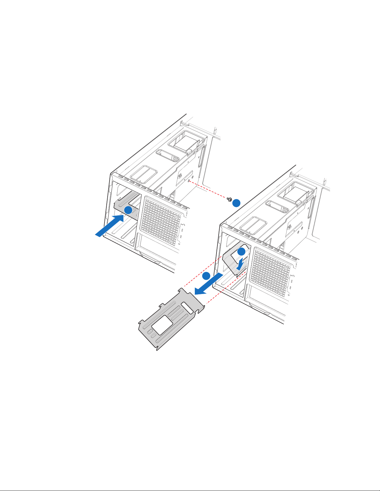
7. Remove screw (see letter “A” in the following figure) securing center divider to the
power supply cage. Push center divider straight back (see letter “B”) to release tabs
from chassis slots. Then, while holding the right edge of the center divider at a
downward angle, disengage tabs from chassis wall by pushing center divider up
and sideways (see letter “C”). Remove center divider from power supply cage (see
letter “D”).
A
B
C
D
Figure 59. Removing Center Divider
TP00696
Intel® Server Chassis SC5400 User’s Guide 55
Page 74

8. Loosen thumb screw (see letter “A” in the following figure) securing the power
distribution board to the chassis. Lift the power distribution board off of the
standoffs (see letter “B”) and then remove it through the back of the power supply
cage (see letter “C”). You may have to feed the power cables through the power
supply cage while removing the power distribution board.
B
A
C
TP00698
Note: Cables on back of power distribution board not shown to clarify insertion process.
Figure 60. Removing Power Distribution Board
56 Intel® Server Chassis SC5400 User’s Guide
Page 75

9. Insert new power distribution board into power supply cage (see letter “A” in the
following figure). Try to route the power cables to the appropriate area at the time
of insertion (see Steps 9 and 10 below). Position the power distribution board on the
four standoffs inside the power supply cage. Push down on the power distribution
board to securely attach it to the standoffs (see letter “B”). Tighten thumb screw
(see letter “C”).
B
C
A
TP00693
Note: Cables on back of power distribution board not shown to clarify insertion process.
Figure 61. Securing Power Distribution Board to Power Supply Cage
10. Connect the P1, P14, and P16 cables to the server board. See the Intel
®
server
board Quick Start User’s Guide or User Guide for appropriate connection
locations.
11. Reconnect power cables to other chassis components as appropriate.
Intel® Server Chassis SC5400 User’s Guide 57
Page 76

12. Reinstall center divider (see letter “A” in the following figure) and secure to chassis
with one screw (see letter “B”).
B
A
C
TP00843
Figure 62. Re-installing Center Divider
13. Insert hot swap power supply(ies) into chassis. Replace shipping screw(s) (see
letter “A” in the following figure) if shipping chassis to another location.
A
AF000603
Figure 63. Installing Hot Swap Power Supply into Chassis
58 Intel® Server Chassis SC5400 User’s Guide
Page 77

14. Re-install the memory and processor air ducts. For instructions, see “Installing the
Processor and Memory Air Ducts” on page 21.
15. Re-install the chassis cover. For instructions, see “Installing the Chassis Cover” on
page 17.
16. Plug all peripheral devices and the AC power cable into the server.
17. Power up the server.
Replacing the Control Panel
The steps for replacing the front control panel and the Intel® Local Control Panel are
nearly identical. Use the following steps for both varieties of the control panel. Where
necessary, differences between the two control panels are noted.
Your server must be operated with a control panel installed.
Caution: The control panel is NOT hot swappable. Before removing or replacing the control panel,
you must first take the server out of service, turn off all peripheral devices connected to
the system, turn off the system by pressing the power button, and unplug the AC power
cord from the system or wall outlet.
1. Observe the safety and ESD precautions at the beginning of this book.
2. Power down the server and unplug all peripheral devices and the AC power cable.
3. Remove the chassis cover. For instructions, see “Removing the Chassis Cover” on
page 16.
4. Remove the front bezel if it is installed. For instructions, see “Removing and
Installing the Front Bezel” on page 18.
5. Press the latch at the back of the control panel.
6. Slide the control panel out through the front of the chassis far enough so that you
can reach the front panel and USB cable connectors at the rear of the control panel.
7. Disconnect cables.
8. Install the control panel module into the chassis.
9. Reconnect cables.
10. (Optional) Install the front bezel. For instructions, see “Removing and Installing the
Front Bezel” on page 18.
11. Install the chassis cover. For instructions, see “Installing the Chassis Cover” on
page 17.
12. Plug all peripheral devices and the AC power cable into the server.
13. Power up the server.
Intel® Server Chassis SC5400 User’s Guide 59
Page 78

Installing and/or Removing a Server Board
Note: The server board you can install in your chassis depends upon the chassis model.
To install or remove a server board, do the following:
1. Observe the safety and ESD precautions at the beginning of this book.
2. Power down the server and unplug all peripheral devices and the AC power cable.
3. Remove the chassis cover. For instructions, see “Removing the Chassis Cover” on
page 16.
4. Remove the front bezel assembly if it is installed. For instructions, see “Removing
the Bezel Assembly (Pedestal Only)” on page 18.
5. Remove any PCI add-in boards that are present. For instructions, see “Removing
PCI Add-in Board(s)” on page 45.
6. Remove the processor and memory air ducts. For instructions, see “Removing the
Processor and Memory Air Ducts” on page 20.
7. If installing a server board
that shipped with your Intel® server board for installation instructions. Use the
mounting screws, bumpers and standoffs (if necessary) that came with your chassis
to secure the server board to the chassis. Make sure the server board is properly
seated and then tighten the screws firmly, starting with the screws at the center of
the server board. Make cable connections per instructions in the Intel® server board
User Guide and/or Quick Start User’s Guide.
8. If removing a server board
Remove the mounting screws, starting with the screws at the center of the server
board. Remove the server board.
9. Re-install the processor and memory air ducts. For instructions, see “Installing the
Processor and Memory Air Ducts” on page 21.
10. If desired, install any PCI Add-in boards. For instructions, see “Installing PCI Add-
in Board(s)” on page 47.
11. Re-install the front bezel assembly. For instructions, see “Installing the Front Bezel
(Pedestal Only)” on page 19.
12. Re-install the chassis cover. For instructions, see “Installing the Chassis Cover” on
page 17.
13. Plug all peripheral devices and the AC power cable into the server.
14. Power up the server.
, refer to the User Guide and/or Quick Start User’s Guide
, disconnect all cables connected to the server board.
60 Intel® Server Chassis SC5400 User’s Guide
Page 79

Connecting and Disconnecting Cables to or from Server Board
Caution: Use caution when routing cables to ensure that cables do not obstruct fan airflow.
1. See your Intel
connection locations.
2. If your server has a hot swap power supply, secure the cables (that route toward the
server board) to the chassis.
Connecting Cables to Server Board
1. If your server has a hot swap power supply, connect the cables (that route toward
the server board) to the chassis.
2. See your Intel
connection locations.
Removing Cables from Server Board(s)
1. If your server has a hot swap power supply, remove the cables (that route toward
the server board) to the chassis.
2. See your Intel
connection locations.
®
Server Board User Guide or Quick Start User’s Guide for cable
®
Server Board User Guide or Quick Start User’s Guide for cable
®
Server Board User Guide or Quick Start User’s Guide for cable
Intel® Server Chassis SC5400 User’s Guide 61
Page 80

62 Intel® Server Chassis SC5400 User’s Guide
Page 81

3 Technical Reference
Power Supply Specifications
670-W Single Power Supply Input Voltages
• 100-127V at 50/60 Hz; 12A max.
• 200-240V at 50/60 Hz; 7A max.
670-W Single Power Supply Output Voltages
The following table lists the total wattage available from the power subsystem for each
voltage. Ensure that your loads do not exceed the combined total wattage of 670 Watts.
For information about calculating the power usage for your configuration, see
“Calculating Power Usage” on page 65.
Table 6. 670-W Power Supply Output Capability
Voltage Maximum Current
+3.3 V 24 A
+5.0 V 30 A
+5 V Standby 3 A
+12.0 48 A
-12.0 V 0.5 A
Warnin g : Do not exceed a combined power output of 170 Watts for the +5 V and +3.3 V outputs.
Exceeding a combined 170 Watts will overload the power subsystem and may cause the
power supplies to overheat and malfunction.
The expansion slots on the server board are rated for no more than 25 Watts for any one
slot. The average current usage per slot should not exceed 13 Watts.
830-W Single Power Input Voltages
• 100-127 V∼ at 50/60 Hz; 14 A max.
• 200-240 V∼ at 50/60 Hz; 8 A max.
Intel® Server Chassis SC5400 User’s Guide 63
Page 82

830-W Single Power Supply Output Voltages
The following table lists the total wattage available from the power subsystem for each
voltage. If you configure your system heavily, ensure that your loads do not exceed the
combined total wattage of 800 Watts. For information about calculating the power usage
for your configuration, see “Calculating Power Usage” on page 65.
Table 7. 830-W Power Supply Output Capability
Voltage Maximum Current
+3.3 V 25 A
+5.0 V 33 A
+5 V Standby 3 A
+12.0 51 A
-12.0 V 0.5 A
Warnin g : Do not exceed a combined power output of 170 Watts for the +5 V and +3.3 V outputs.
Exceeding a combined 170 Watts will overload the power subsystem and may cause the
power supplies to overheat and malfunction.
The expansion slots on the server board are rated for no more than 25 Watts for any one
slot. The average current usage per slot should not exceed 13 Watts.
System Environmental Specifications
Table 8. Environmental Specifications
Non-operating: -40 ° to 70 °C.
Temperature
Humidity
Shock
Acoustic noise
Electrostatic discharge
(ESD)
Operating: 10 ° to 35 °C; derated 0.5 °C for every 1000 ft. (305 m) to
a maximum of 10,000 ft.
Non-operating: 90% relative humidity (non-condensing) at 30 °C.
Operating: 2.0 g, 11 msec, 1/2 sine
Packaged: Operational after an 18" free fall.
UP, DP, BRP configurations - 5.5 BA LWA idle; 6.0 BA LWA typical
operating
Tested to 15 kilovolts (kV); no component damage.
64 Intel® Server Chassis SC5400 User’s Guide
Page 83

Current Usage
Calculating Power Usage
The total combined wattage for your configuration must be less than the wattage rating
for your power supply. Use the two worksheets in this section to calculate the total used
by your configuration. For current and voltage requirements of add-in boards and
peripherals, see your vendor documents.
Worksheet, Calculating DC Power Usage
Table 9. Power Usage Worksheet
Current (maximum) at voltage level:
Device
Baseboard, Front Panel
Board and Fans
Processor(s)
Memory
3.5-inch Diskette Drive
CD-ROM Drive
Second 5.25-inch Device
Third 5.25-inch Device
1st Hard Drive
2nd Hard Drive
3rd Hard Drive
4th Hard Drive
5th Hard Drive
6th Hard Drive
Expansion Board 1
Expansion Board 2
Expansion Board 3
Expansion Board 4
Expansion Board 5
Expansion Board 6
Intel® Remote Management
Module
Control Panel
Total Current
+3.3
V
+5 V –5 V
+12 V–12
V
5 V Standby
Intel® Server Chassis SC5400 User’s Guide 65
Page 84
Worksheet, Total Combined Power Used by the Server
3. From the previous worksheet, enter the total current for each column.
4. Multiply the voltage by the total current to get the total wattage for each voltage
level.
Add the total wattage for each voltage level to arrive at the total combined power usage
for the power subsystem.
Table 10. Power Usage Worksheet 2
Voltage level and total current
(V X A = W)
(+3.3 V) X (______ A) ________ W
(+5 V) X (______ A) ________ W
(+12 V) X (______ A) ________ W
(–12 V) X (______ A) ________ W
(5 V standby) X (______ A) ________ W
Total Combined Wattage ________ W
Total Watts
for each voltage level
Caution: Do not exceed a combined power output of 170 Watts for the +5 V and +3.3 V outputs.
Exceeding a combined 170 Watts will overload the power subsystem and may cause the
power supplies to overheat and malfunction.
66 Intel® Server Chassis SC5400 User’s Guide
Page 85

Appendix B: Regulatory and
Compliance Information
Product Regulatory Compliance
Warnin g : To ensure regulatory compliance, you must adhere to the assembly instructions in this
guide to ensure and maintain compliance with existing product certifications and
approvals. Use only the described, regulated components specified in this guide. Use of
other products/components will void the UL listing and other regulatory approvals of the
product and will most likely result in noncompliance with product regulations in the
region(s) in which the product is sold.
To help ensure EMC compliance with your local regional rules and regulations, before
computer integration, make sure that the server system, power supply, and other modules
have passed EMC testing using a server board with a microprocessor from the same
family (or higher) and operating at the same (or higher) speed as the microprocessor used
on this server board. The final configuration of your end system product may require
additional EMC compliance testing. For more information, please contact your local Intel
representative.
This is an FCC Class A device. Integration of it into a Class B system does not result in a
Class B device.
Product Safety Compliance
This server chassis product, when correctly integrated per this guide, complies with the
following safety and electromagnetic compatibility (EMC) regulations.
Intended Application
This product was evaluated as Information Technology Equipment (ITE), which may be
installed in offices, schools, computer rooms, and similar commercial type locations. The
suitability of this product for other product categories and environments (such as: medical,
industrial, telecommunications, NEBS, residential, alarm systems, test equipment, etc.),
other than an ITE application, may require further evaluation.
Intel® Server Chassis SC5400 User’s Guide 71
Page 86
Product Regulatory Compliance References
The following table references Server Chassis Compliance and markings that may appear
on the product. Markings below are typical markings however, may vary or be different
based on how certification is obtained.
Note: Certifications Emissions requirements are to Class A.
Table 11. Product Regulatory Compliance Markings
Compliance Regional
Description
Australia / New Zealand AS/NZS 3548
Argentina IRAM
Belarus Belarus
Canada / USA CSA 60950 - UL
Canada / USA Industry Canada
Compliance
Reference
(Emissions)
Certification
(Safety)
Certification
60950 (Safety)
ICES-003
(Emissions)
Compliance Reference Marking Example
N232
None Required
CANADA ICES-003 CLASS A
CANADA NMB-003 CLASSE A
FCC
CFR 47, Part 15
(Emissions)
China CNCA - CB4943
(Safety)
GB 9254
(Emissions)
GB17625
(Harmonics)
72 Intel® Server Chassis SC5400 User’s Guide
Page 87

Table 11. Product Regulatory Compliance Markings
Compliance Regional
Description
CENELEC Europe Low Voltage
Germany GS Certification -
International CB Certification -
Compliance
Reference
Directive 93/68/
EEC;
EMC Directive 89/
336/EEC
EN55022
(Emissions)
EN55024
(Immunity)
EN61000-3-2
(Harmonics)
EN61000-3-3
(Voltage Flicker)
CE Declaration of
Conformity
EN60950
IEC60950
CISPR 22 /
CISPR 24
Compliance Reference Marking Example
None Required
Japan VCCI Certification
Korea RRL Certification
MIC Notice No.
1997-41 (EMC) &
1997-42 (EMI)
Intel® Server Chassis SC5400 User’s Guide 73
Page 88
Table 11. Product Regulatory Compliance Markings
Compliance Regional
Description
Russia GOST-R
Ukraine Ukraine
Taiwan BSMI CNS13438
Compliance
Reference
Certification
GOST R 29216-
91 (Emissions)
GOST R 50628-
95 (Immunity)
Certification
Compliance Reference Marking Example
None Required
R33025
74 Intel® Server Chassis SC5400 User’s Guide
Page 89

Electromagnetic Compatibility Notices
FCC Verification Statement (USA)
This device complies with Part 15 of the FCC Rules. Operation is subject to the following
two conditions: (1) this device may not cause harmful interference, and (2) this device
must accept any interference received, including interference that may cause undesired
operation.
For questions related to the EMC performance of this product, contact:
Intel Corporation
5200 N.E. Elam Young Parkway
Hillsboro, OR 97124-6497
1-800-628-8686
This equipment has been tested and found to comply with the limits for a Class A digital
device, pursuant to Part 15 of the FCC Rules. These limits are designed to provide
reasonable protection against harmful interference in a residential installation. This
equipment generates, uses, and can radiate radio frequency energy and, if not installed and
used in accordance with the instructions, may cause harmful interference to radio
communications. However, there is no guarantee that interference will not occur in a
particular installation. If this equipment does cause harmful interference to radio or
television reception, which can be determined by turning the equipment off and on, the
user is encouraged to try to correct the interference by one or more of the following
measures:
• Reorient or relocate the receiving antenna.
• Increase the separation between the equipment and the receiver.
• Connect the equipment to an outlet on a circuit other than the one to which the
receiver is connected.
• Consult the dealer or an experienced radio/TV technician for help.
Any changes or modifications not expressly approved by the grantee of this device could
void the user's authority to operate the equipment. The customer is responsible for
ensuring compliance of the modified product.
Only peripherals (computer input/output devices, terminals, printers, etc.) that comply
with FCC Class A or B limits may be attached to this computer product. Operation with
noncompliant peripherals is likely to result in interference to radio and TV reception.
All cables used to connect to peripherals must be shielded and grounded. Operation with
cables, connected to peripherals, that are not shielded and grounded may result in
interference to radio and TV reception.
Intel® Server Chassis SC5400 User’s Guide 75
Page 90

Industry Canada (ICES-003)
Cet appareil numérique respecte les limites bruits radioélectriques applicables aux
appareils numériques de Classe A prescrites dans la norme sur le matériel brouilleur:
"Apparelis Numériques", NMB-003 édictee par le Ministre Canadian des
Communications.
English translation of the notice above:
This digital apparatus does not exceed the Class A limits for radio noise emissions from
digital apparatus set out in the interference-causing equipment standard entitled: "Digital
Apparatus," ICES-003 of the Canadian Department of Communications.
Europe (CE Declaration of Conformity)
This product has been tested in accordance to, and complies with the Low Voltage
Directive (73/23/EEC) and EMC Directive (89/336/EEC). The product has been marked
with the CE Mark to illustrate its compliance.
VCCI (Japan)
English translation of the preceding notice:
This is a Class A product based on the standard of the Voluntary Control Council for
Interference (VCCI) from Information Technology Equipment. If this is used near a radio
or television receiver in a domestic environment, it may cause radio interference. Install
and use the equipment according to the instruction manual.
BSMI (Taiwan)
The BSMI Certification Marking and EMC warning is located on the outside rear area of
the product.
76 Intel® Server Chassis SC5400 User’s Guide
Page 91
Korean Compliance (RRL)
Following is the RRL certification information for Korea.
English translation of the notice above:
1. Type of Equipment (Model Name): On License and Product
2. Certification No.: On RRL certificate. Obtain certificate from local Intel
representative
3. Name of Certification Recipient: Intel Corporation
4. Date of Manufacturer: Refer to date code on product
5. Manufacturer/Nation: Intel Corporation/Refer to country of origin marked on
product
CNCA (CCC-China)
The CCC Certification Marking and EMC warning is located on the outside rear area of
the product.
Product Ecology Compliance
Intel has a system in place to restrict the use of banned substances in accordance with
world wide product ecology regulatory requirements. The following is Intel's product
ecology compliance criteria.
Intel® Server Chassis SC5400 User’s Guide 77
Page 92

Table 12. Product Ecology Compliance Markings
Compliance
Regional
Description
California California Code of Regulations, Title 22,
Division 4.5; Chapter 33: Best
Management Practices for Perchlorate
Materials.
China China RoHS
Administrative Measures on the Control of
Pollution Caused by Electronic
Information Products" (EIP) #39. Referred
to as China RoHS.
Mark requires to be applied to retail
products only. Mark used is the
Environmental Friendly Use Period
(EFUP). Number represents years.
China Recycling (GB18455-2001)
Mark requires to be applied to be retail
product only. Marking applied to bulk
packaging and single packages. Not
applied to internal packaging such as
plastics, foams, etc.
Compliance Reference
Compliance Reference
Marking Example
Special handling may apply. See
www.dtsc.ca.gov/
hazardouswaste/perchlorate.
This notice is required by
California Code of Regulations,
Title 22, Division 4.5; Chapter 33:
Best Management Practices for
Perchlorate Materials. This
product / part includes a battery
which contains Perchlorate
material.
Intel Internal
Specification
Europe Waste Electrical and Electronic
78 Intel® Server Chassis SC5400 User’s Guide
All materials, parts and subassemblies
must not contain restricted materials as
defined in Intel's Environmental Product
Content Specification of Suppliers and
Outsourced Manufacturers - http://
supplier.intel.com/ehs/environmental.htm
Equipment (WEEE) Directive 2002/96/
EC - Mark applied to system level
products only.
None Required
Page 93

Compliance
Regional
Description
Compliance Reference
Compliance Reference
Marking Example
Europe European Directive 2002/95/EC -
Restriction of Hazardous Substances
(RoHS). Threshold limits and banned
substances are noted below.
Quantity limit of 0.1% by mass (1000
PPM) for: Lead, Mercury, Hexavalent
Chromium, Polybrominated Biphenyls
Diphenyl Ethers (PBB/PBDE)
Quantity limit of 0.01% by mass (100
PPM) for: Cadmium
Germany German Green Dot
Applied to Retail Packaging Only for
Boxed Boards
Intel Internal
Specification
International ISO11469 -
All materials, parts and subassemblies
must not contain restricted materials as
defined in Intel's Environmental Product
Content Specification of Suppliers and
Outsourced Manufacturers - http://
supplier.intel.com/ehs/environmental.htm.
Plastic parts weighing >25gm
are intended to be marked with per
ISO11469.
None Required.
None Required
>PC/ABS<
Recycling Markings - Fiberboard (FB) and
Cardboard (CB) are marked with
international recycling marks. Applied to
outer bulk packaging and single package.
Japan Japan Recycling
Applied to Retail Packaging Only for
Boxed Boards
Intel® Server Chassis SC5400 User’s Guide 79
Page 94

Other Markings
Simplified Chinese
注意:
本设备包括多条电源系统电缆。
为避免遭受电击,
在进行维修之前应断开两(2)
条电源系统电缆
Traditional Chinese
注意:
本設備包括多條電源系統電纜。
遭受電擊,
在進行維修之前應斷開兩(2)
條電源系統電纜
Table 13. Other Markings
Compliance
Description
Stand-by
Power
Multiple Power
Cords
Compliance Reference
Stand-by Power Warnings
Applied to product if stand-by power
switch is used.
Multiple Power Cords Warnings
Applied to product if more than one power
cord is used.
Compliance Reference
Marking Example
English:
This unit has more than one
power supply cord. To reduce
the risk of electrical shock,
disconnect (2) two power supply
cords before servicing.
80 Intel® Server Chassis SC5400 User’s Guide
German:
Dieses Geräte hat mehr als ein
Stromkabel. Um eine Gefahr des
elektrischen Schlages zu
verringern trennen sie beide (2)
Stromkabeln bevor
Instandhaltung
Page 95

Compliance
Description
Compliance Reference
Compliance Reference
Marking Example
Ground
Connection
Ground Connection Warnings Line1 :
Regulated Specified Components
To maintain the UL listing and compliance to other regulatory certifications and/or
declarations, the following regulated components must be used and conditions adhered to.
Interchanging or use of other components will void the UL listing and other product
certifications and approvals.
“WARNING:”
Swedish on line2:
“Apparaten skall anslutas till
jordat uttag, när den ansluts till
ett nätverk."
Finnish on line 3:
"Laite on liitettävä
suojamaadoituskoskettimilla
varustettuun pistorasiaan."
English on line 4:
"Connect only to a properly earth
grounded outlet."
Updated product information for configurations can be found on the Intel Server Builder
Web site at the following URL: http://channel.intel.com/go/serverbuilder
If you do not have access to Intel's Web address, please contact your local Intel
representative.
• Server Chassis: (base chassis is provided with power supply and fans) - UL listed.
• Server board: you must use an Intel server board - UL recognized.
• Add-in boards: must have a printed wiring board flammability rating of minimum
UL94V-1. Add-in boards containing external power connectors and/or lithium
batteries must be UL recognized or UL listed. Any add-in board containing modem
telecommunication circuitry must be UL listed. In addition, the modem must have
the appropriate telecommunications, safety, and EMC approvals for the region in
which it is sold.
• Peripheral Storage Devices: must be a UL recognized or UL listed accessory and
TUV or VDE licensed. Total server configuration is not to exceed the maximum
loading conditions of the power supply.
Intel® Server Chassis SC5400 User’s Guide 81
Page 96

End-of-Life / Product Recycling
Product recycling and end-of-life take-back systems and requirements vary by country.
Contact the retailer or distributor of this product for information about product recycling
and / or take-back.
82 Intel® Server Chassis SC5400 User’s Guide
Page 97
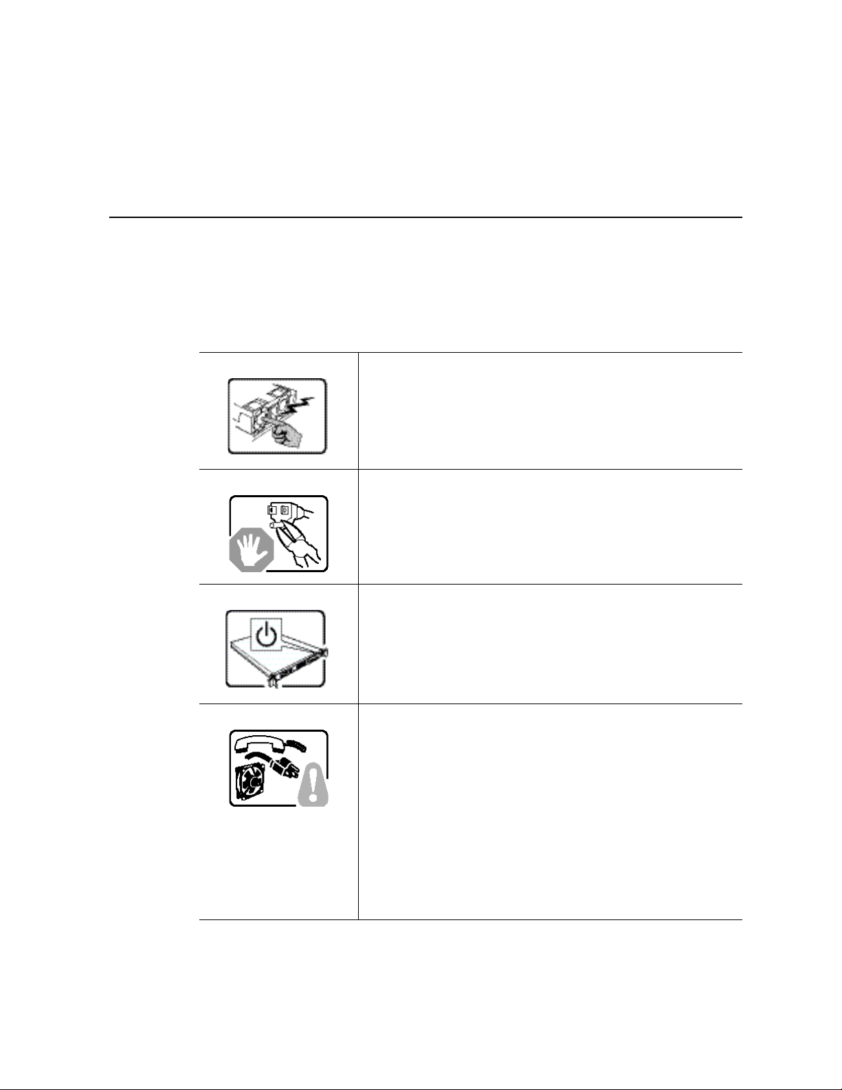
Appendix E: Installation/Assembly
Safety Instructions
English
The power supply in this product contains no user-serviceable parts.
Refer servicing only to qualified personnel.
Do not attempt to modify or use the supplied AC power cord if it is
not the exact type required. A product with more than one power
supply will have a separate AC power cord for each supply.
The power button on the system does not turn off system AC power.
To remove AC power from the system, you must unplug each AC
power cord from the wall outlet or power supply.
The power cord(s) is considered the disconnect device to the main
(AC) power. The socket outlet that the system plugs into shall be
installed near the equipment and shall be easily accessible.
SAFETY STEPS: Whenever you remove the chassis covers to
access the inside of the system, follow these steps:
1. Turn off all peripheral devices connected to the system.
2. Turn off the system by pressing the power button.
3. Unplug all AC power cords from the system or from wall
outlets.
4. Label and disconnect all cables connected to I/O connectors
or ports on the back of the system.
5. Provide some electrostatic discharge (ESD) protection by
wearing an antistatic wrist strap attached to chassis ground of
the system-any unpainted metal surface-when handling
components.
6. Do not operate the system with the chassis covers removed.
Intel® Server Chassis SC5400 User’s Guide 117
Page 98

After you have completed the six SAFETY steps above, you can
remove the system covers. To do this:
1. Unlock and remove the padlock from the back of the system if
a padlock has been installed.
2. Remove and save all screws from the covers.
3. Remove the cover(s).
For proper cooling and airflow, always reinstall the chassis covers
before turning on the system. Operating the system without the
covers in place can damage system parts. To install the covers:
1. Check first to make sure you have not left loose tools or parts
inside the system.
2. Check that cables, add-in boards, and other components are
properly installed.
3. Attach the covers to the chassis with the screws removed
earlier, and tighten them firmly.
4. Insert and lock the padlock to the system to prevent
unauthorized access inside the system.
5. Connect all external cables and the AC power cord(s) to the
system.
A microprocessor and heat sink may be hot if the system has been
running. Also, there may be sharp pins and edges on some board
and chassis parts. Contact should be made with care. Consider
wearing protective gloves.
Danger of explosion if the battery is incorrectly replaced. Replace
only with the same or equivalent type recommended by the
equipment manufacturer. Dispose of used batteries according to
manufacturer's instructions.
The system is designed to operate in a typical office environment.
Choose a site that is:
• Clean and free of airborne particles (other than normal room
dust).
• Well ventilated and away from sources of heat including direct
sunlight.
• Away from sources of vibration or physical shock.
• Isolated from strong electromagnetic fields produced by
electrical devices.
• In regions that are susceptible to electrical storms, we
recommend you plug your system into a surge suppresser and
disconnect telecommunication lines to your modem during an
electrical storm.
• Provided with a properly grounded wall outlet.
• Provided with sufficient space to access the power supply
cord(s), because they serve as the product's main power
disconnect.
118 Intel® Server Chassis SC5400 User’s Guide
Page 99
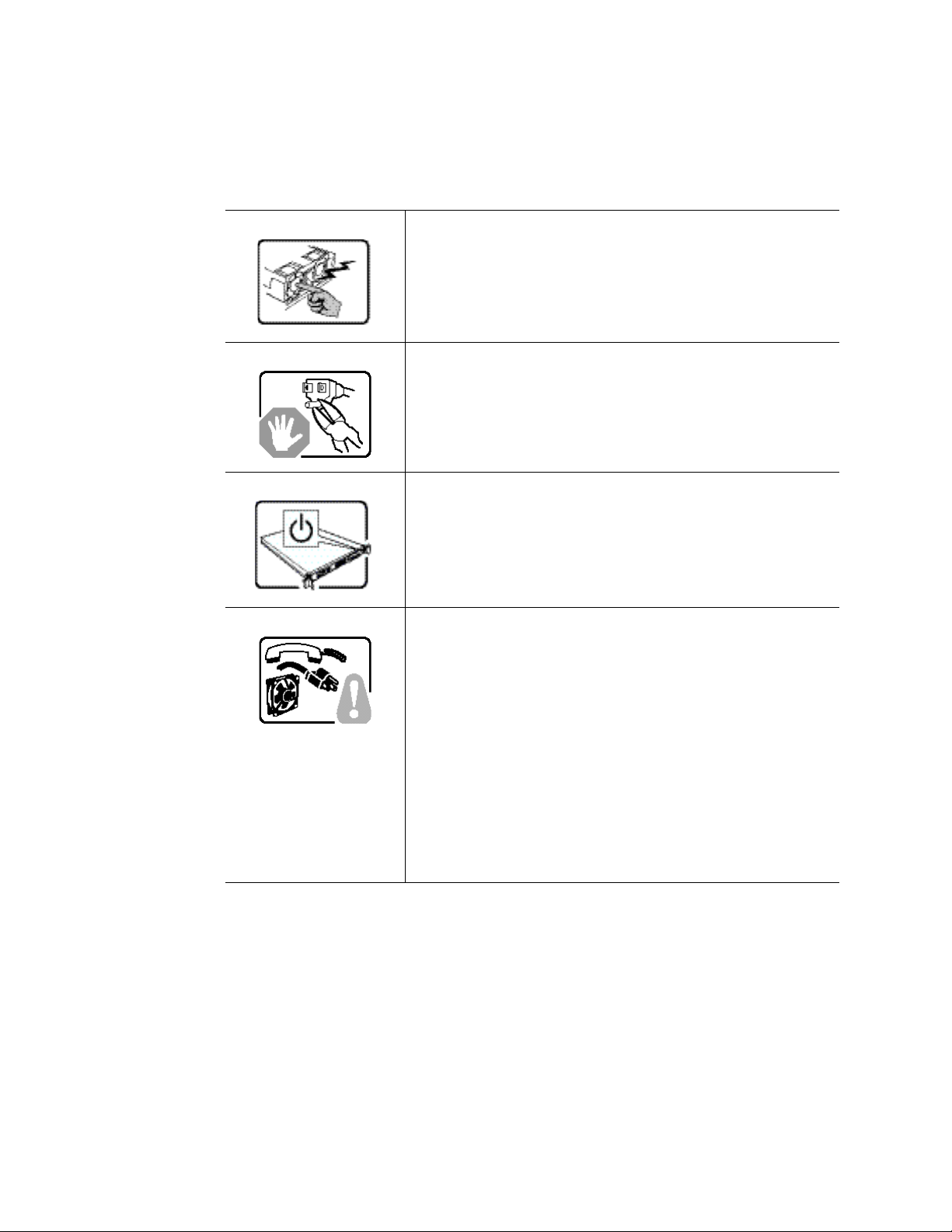
Deutsch
Benutzer können am Netzgerät dieses Produkts keine Reparaturen
vornehmen. Das Produkt enthält möglicherweise mehrere
Netzgeräte. Wartungsarbeiten müssen von qualifizierten Technikern
ausgeführt werden.
Versuchen Sie nicht, das mitgelieferte Netzkabel zu ändern oder zu
verwenden, wenn es sich nicht genau um den erforderlichen Typ
handelt. Ein Produkt mit mehreren Netzgeräten hat für jedes
Netzgerät ein eigenes Netzkabel.
Der Wechselstrom des Systems wird durch den Ein-/Aus-Schalter
für Gleichstrom nicht ausgeschaltet. Ziehen Sie jedes
Wechselstrom-Netzkabel aus der Steckdose bzw. dem Netzgerät,
um den Stromanschluß des Systems zu unterbrechen.
SICHERHEISMASSNAHMEN: Immer wenn Sie die
Gehäuseabdeckung abnehmen um an das Systeminnere zu
gelangen, sollten Sie folgende Schritte beachten:
1. Schalten Sie alle an Ihr System angeschlossenen
Peripheriegeräte aus.
2. Schalten Sie das System mit dem Hauptschalter aus.
3. Ziehen Sie den Stromanschlußstecker Ihres Systems aus der
Steckdose.
4. Auf der Rückseite des Systems beschriften und ziehen Sie
alle Anschlußkabel von den I/O Anschlüssen oder Ports ab.
5. Tragen Sie ein geerdetes Antistatik Gelenkband, um
elektrostatische Ladungen (ESD) über blanke Metallstellen
bei der Handhabung der Komponenten zu vermeiden.
6. Schalten Sie das System niemals ohne ordnungsgemäß
montiertes Gehäuse ein.
Intel® Server Chassis SC5400 User’s Guide 119
Page 100
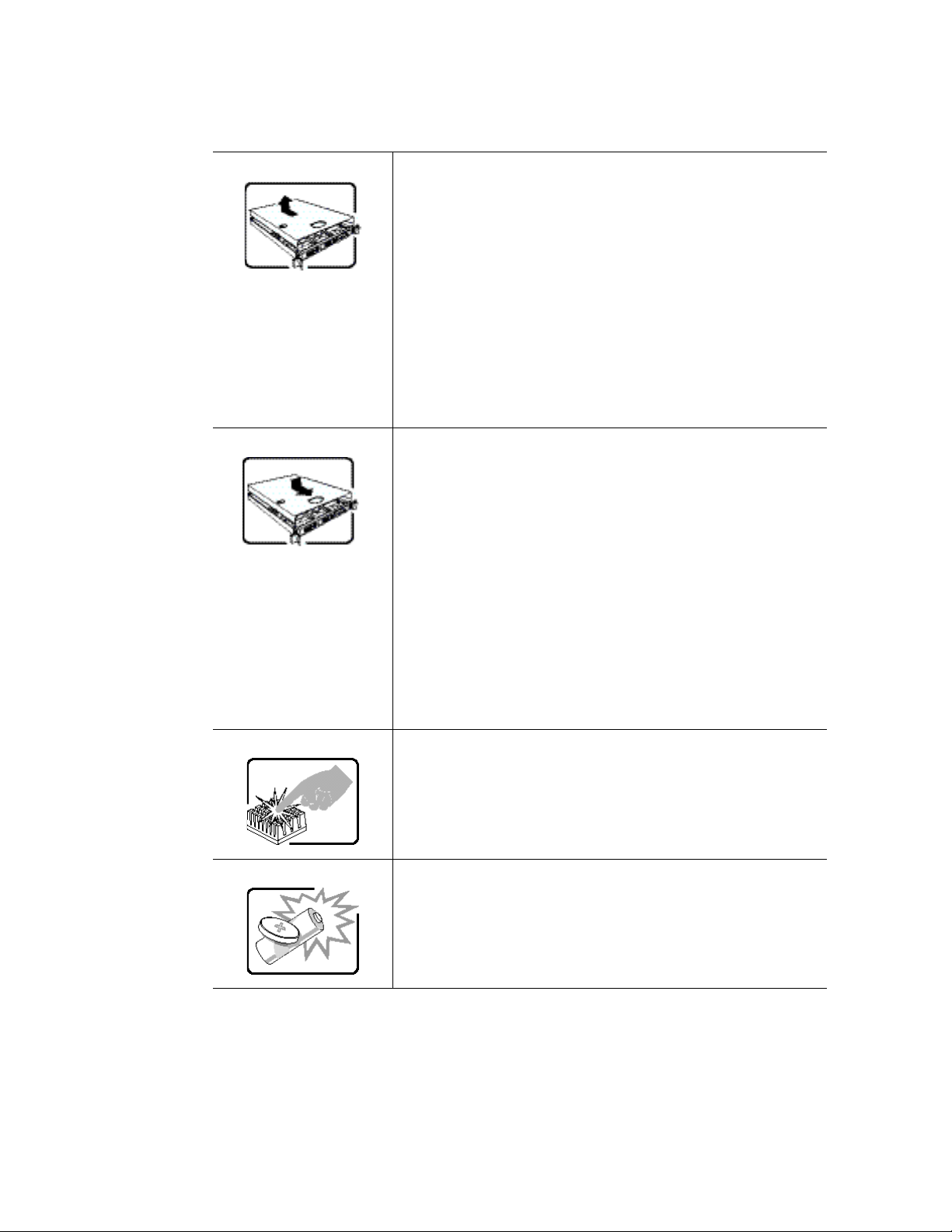
SICHERHEISMASSNAHMEN: Immer wenn Sie die
Gehäuseabdeckung abnehmen um an das Systeminnere zu
gelangen, sollten Sie folgende Schritte beachten:
1. Schalten Sie alle an Ihr System angeschlossenen
Peripheriegeräte aus.
2. Schalten Sie das System mit dem Hauptschalter aus.
3. Ziehen Sie den Stromanschlußstecker Ihres Systems aus der
Steckdose.
4. Auf der Rückseite des Systems beschriften und ziehen Sie
alle Anschlußkabel von den I/O Anschlüssen oder Ports ab.
5. Tragen Sie ein geerdetes Antistatik Gelenkband, um
elektrostatische Ladungen (ESD) über blanke Metallstellen
bei der Handhabung der Komponenten zu vermeiden.
6. Schalten Sie das System niemals ohne ordnungsgemäß
montiertes Gehäuse ein.
Zur ordnungsgemäßen Kühlung und Lüftung muß die
Gehäuseabdeckung immer wieder vor dem Einschalten installiert
werden. Ein Betrieb des Systems ohne angebrachte Abdeckung
kann Ihrem System oder Teile darin beschädigen. Um die
Abdeckung wieder anzubringen:
1. Vergewissern Sie sich, daß Sie keine Werkzeuge oder Teile
im Innern des Systems zurückgelassen haben.
2. Überprüfen Sie alle Kabel, Zusatzkarten und andere
Komponenten auf ordnungsgemäßen Sitz und Installation.
3. Bringen Sie die Abdeckungen wieder am Gehäuse an, indem
Sie die zuvor gelösten Schrauben wieder anbringen. Ziehen
Sie diese gut an.
4. Bringen Sie die Verschlußeinrichtung (Padlock) wieder an und
schließen Sie diese, um ein unerlaubtes Öffnen des Systems
zu verhindern.
5. Schließen Sie alle externen Kabel und den AC
Stromanschlußstecker Ihres Systems wieder an.
Der Mikroprozessor und der Kühler sind möglicherweise erhitzt,
wenn das System in Betrieb ist. Außerdem können einige Platinen
und Gehäuseteile scharfe Spitzen und Kanten aufweisen. Arbeiten
an Platinen und Gehäuse sollten vorsichtig ausgeführt werden. Sie
sollten Schutzhandschuhe tragen.
Bei falschem Einsetzen einer neuen Batterie besteht
Explosionsgefahr. Die Batterie darf nur durch denselben oder einen
entsprechenden, vom Hersteller empfohlenen Batterietyp ersetzt
werden. Entsorgen Sie verbrauchte Batterien den Anweisungen des
Herstellers entsprechend.
120 Intel® Server Chassis SC5400 User’s Guide
 Loading...