

Intel SC5300BRP, SC5300BD2 - Server Platform - 0 MB RAM, SC5300 Technical Product Specification
Page 1

Intel® Server Chassis
SC5300 5U Kit
Technical Product Specification
C67699-002
Revision 1.31
January, 2006
Enterprise Platforms and Services Marketing
Page 2
Intel® Server Chassis SC5300 5U Kit TPS Introduction
g
Revision History
Date Revision Number Modifications
June 18, 2004 1.0 Initial Release
June 25, 2004 1.1 Format Updates
July 20 , 2004 1.1.1 Format updates
Jan 5, 2005 1.2 SATA and SCSI backplane updates Incorporated T.H.
Comments. Added BRP Added Errata/Inte
Jan 16, 2006 1.3 SATA backplane updates – added SAS compatibility
Jan 16, 2006 1.31 Modified Sections 1.3 and 1.4
ration Appendix
Disclaimers
Information in this document is provided in connection with Intel® products. No license, express or
implied, by estoppel or otherwise, to any intellectual property rights is granted by this document. Except
as provided in Intel's Terms and Conditions of Sale for such products, Intel assumes no liability
whatsoever, and Intel disclaims any express or implied warranty, relating to sale and/or use of Intel
products including liability or warranties relating to fitness for a particular purpose, merchantability, or
infringement of any patent, copyright or other intellectual property right. Intel products are not intended for
use in medical, life saving, or life sustaining applications. Intel may make changes to specifications and
product descriptions at any time, without notice.
Designers must not rely on the absence or characteristics of any features or instructions marked
"reserved" or "undefined." Intel reserves these for future definition and shall have no responsibility
whatsoever for conflicts or incompatibilities arising from future changes to them.
The Intel® Server Chassis SC5300 may contain design defects or errors known as errata which may
cause the product to deviate from published specifications. Current characterized errata are available on
request.
Intel Corporation server baseboards contain a number of high-density VLSI and power delivery
components that need adequate airflow to cool. Intel’s own chassis are designed and tested to meet the
intended thermal requirements of these components when the fully integrated system is used together. It
is the responsibility of the system integrator that chooses not to use Intel developed server building
blocks to consult vendor datasheets and operating parameters to determine the amount of air flow
required for their specific application and environmental conditions. Intel Corporation can not be held
responsible if components fail or the server board does not operate correctly when used outside any of
their published operating or non-operating limits.
Intel, Pentium, Itanium, and Xeon are trademarks or registered trademarks of Intel Corporation.
*Other brands and names may be claimed as the property of others.
Copyright © Intel Corporation 2004-2005.
Revision 1.31
1
Page 3

Introduction Intel® Server Chassis SC5300 5U Kit TPS
Table of Contents
1. Introduction ...........................................................................................................12
1.1 Intel® Server Chassis SC5300 Design Features........................................12
1.2 Intel® Server Chassis SC5300BASE Summary ......................................... 14
1.3 Intel® Server Chassis SC5300BRP Summary............................................ 15
1.4 Intel® Server Chassis SC5300LX Summary...............................................15
2. Chassis Features...................................................................................................17
2.1 Chassis Dimensions and Weight ...............................................................17
2.2 System Colors............................................................................................ 17
2.2.1 Pedestal and Rack Mount Features...........................................................17
2.3 Security......................................................................................................18
2.4 I/O Panel....................................................................................................18
2.5 Standard and Optional Hot Swap Drive Bays ............................................ 19
2.6 5.25-inch Half-height Peripheral Bays........................................................ 19
2.7 Chassis Views............................................................................................ 20
3. Chassis Power Subsystem...................................................................................22
3.1 600-W Power Supply.................................................................................22
3.1.1 Mechanical Outline .................................................................................... 22
3.1.2 Output Wire Harness ................................................................................. 23
3.1.3 600-W Power Supply Airflow and Temperature Rise................................ 28
3.1.4 AC Specifications.......................................................................................28
3.1.5 600-W DC Output Specifications .............................................................. 30
3.1.6 600-W Protection Circuits ......................................................................... 31
3.1.7 600-W Power Supply Control and Indicator Functions...............................32
2 Revision 1.31
Page 4

Intel® Server Chassis SC5300 5U Kit TPS Introduction
3.1.8 Mean Time Between Failures (MTBF) ....................................................... 32
3.2 730-W Power Supply.................................................................................32
3.2.1 730W Power Supply Mechanical Outline................................................... 33
3.2.2 Output Wire Harness ................................................................................ 34
3.2.3 Airflow Requirements and Temperature Rise ............................................ 34
3.2.4 AC Specifications.......................................................................................34
3.2.5 730-W DC Specifications..........................................................................35
3.2.6 730-W Protection Circuits .......................................................................... 37
3.2.7 730-W Power Supply Control and Indicator Functions...............................38
3.2.8 730-W Mean Time Between Failure (MTBF).............................................. 38
3.2.9 Redundant (1+1) Hot Swap Mode.............................................................. 38
3.3 730-W Power Distribution Board................................................................38
3.3.1 Power Distribution Mechanical Overview...................................................39
3.3.2 Temperature Operational Limits................................................................ 41
3.3.3 Electrical Specification...............................................................................41
3.3.4 Protection Circuits...................................................................................... 46
3.3.5 Control and Indicator Functions ................................................................. 46
3.4 SMBus Monitoring Interface....................................................................... 47
3.4.1 Mean Time Between Failures (MTBF) ....................................................... 48
4. System Cooling.....................................................................................................49
4.1 Fan Configuration ......................................................................................49
4.1.1 Processor Passive Heat Sink Cooling Solution.......................................... 49
4.1.2 Base Cooling Solution................................................................................ 50
4.1.2 Redundant Cooling Solution ...................................................................... 50
4.2 Fan Control................................................................................................ 52
Revision 1.31
3
Page 5

Introduction Intel® Server Chassis SC5300 5U Kit TPS
4.3 FAN Header Connector Descriptions......................................................... 52
5. Hard Disk Drive Bays............................................................................................ 53
5.1 Server Chassis SC5300 4HDD and 6HDD SCSI HSBP Overview ............ 53
5.1.1 SCSI Enclosure Management Controller ...................................................53
5.1.2 SCSI Interface............................................................................................ 54
5.1.3 External Memory Device............................................................................54
5.1.4 Hot Swap Power Controller........................................................................ 54
5.1.5 SCSI Drive Connectors..............................................................................54
5.1.6 Power Connectors ..................................................................................... 55
5.1.7 SCA2 SCSI Connector...............................................................................55
5.1.8 68-Pin SCSI Connector..............................................................................56
5.1.9 IPMB (I2C) Header .................................................................................... 58
5.1.10 Power Budget ............................................................................................ 58
5.1.11 Hard Drive Activity and Fault LED.............................................................. 58
5.1.12 SCSI Backplane Status LEDs....................................................................59
5.1.13 SCSI Hot Swap Drive Bay Upgrade Kits.................................................... 61
5.2 SATA/SAS Hot Swap Backplane...............................................................61
5.2.1 Enclosure Management Controller.............................................................63
5.2.2 SATA/SAS Interface .................................................................................. 63
5.2.3 I2C Serial Bus Interface..............................................................................63
5.2.4 General Purpose Input/Output (GPIO)....................................................... 65
5.2.5 External Memory Device............................................................................67
5.2.6 LEDs.......................................................................................................... 67
5.2.7 SATA/SAS Drive Connectors..................................................................... 67
5.2.8 Power Connectors ..................................................................................... 68
4 Revision 1.31
Page 6

Intel® Server Chassis SC5300 5U Kit TPS Introduction
5.2.9 Clock Generation and Distribution ............................................................. 68
5.2.10 7-Pin SATA/SAS Connector – Drive0-Drive5............................................. 69
5.2.11 IPMB Header - IPMB .................................................................................69
5.2.12 SATA/SAS Host I2C Header - I2C_1.......................................................... 70
5.2.13 Power Budget ............................................................................................ 70
5.2.14 Board Layout.............................................................................................. 70
5.2.15 Connector Specifications ........................................................................... 71
5.2.16 SATA/SAS Hot Swap Drive Cage Upgrade Kit..........................................72
6. Front Panel ............................................................................................................73
6.1 Front Panel Board Layout.......................................................................... 73
6.1.1 Front Panel Connectors............................................................................. 73
6.1.2 Front panel JP2 Header (17x2) Pin-out. .................................................... 74
6.1.3 I2C Connectors at J1 and J2 (Not Installed) Pin-out................................... 75
6.1.4 Front Panel Controls and Indicators ........................................................... 75
6.2 Chassis Interconnect .................................................................................78
6.3 Chassis Internal Cables............................................................................. 79
6.3.1 Front Panel Cable...................................................................................... 79
6.3.2 USB Cable and Connectors.......................................................................80
6.3.3 Hot Swap Fan Cables and Connectors......................................................80
6.3.4 SCSI Cable ................................................................................................82
6.3.5 Serial Cable ............................................................................................... 83
6.3.6 SATA Cable ...............................................................................................83
6.3.7 IPMB cable for 6-Drive Bays (4-pin)...........................................................84
6.3.8 I2C Cable for 6-Drive Bays (3-pin).............................................................. 84
7. System-Compatible Server Boards .....................................................................85
Revision 1.31
5
Page 7

Introduction Intel® Server Chassis SC5300 5U Kit TPS
8. Upgrade Accessories............................................................................................86
8.1 AXX6SCSIDB and AXX4SCSIDB Hot Swap SCSI Drive Bays..................86
8.2 SATA/SAS Hot Swap Drive Bay Upgrade Accessory AXX6SASDB.......... 86
8.3 External SCSI Adapter Cable AXXEXTSCSICBL...................................... 86
8.4 Rack Conversion Kit ARIGRACK...............................................................86
9. Reliability, Serviceability, and Availability.......................................................... 87
9.1 MTBF.........................................................................................................87
9.2 Serviceability..............................................................................................87
10. Environmental Limits............................................................................................89
10.1 System Office Environment........................................................................89
10.2 System Environmental Testing .................................................................. 89
11. Product Regulatory Compliance..........................................................................90
11.1 Product Safety Compliance........................................................................90
11.2 Product EMC Compliance..........................................................................90
11.3 Product Regulatory Compliance Markings................................................. 90
11.4 Electromagnetic Compatibility Notices....................................................... 91
11.4.1 USA ...........................................................................................................91
11.4.2 FCC Verification Statement........................................................................92
11.4.3 ICES-003 (Canada) ...................................................................................92
11.4.4 Europe (CE Declaration of Conformity)...................................................... 92
11.4.5 Japan EMC Compatibility...........................................................................92
11.4.6 BSMI (Taiwan)........................................................................................... 93
Appendix A: Intel® Server Chassis SC5300 Spares and Accessories.................. 94
Appendix B: Intel® Server Chassis SC5200, SC5250-E, SC5275-E and SC5300
Common Spares & Accessories Components .........................................................98
6 Revision 1.31
Page 8

Intel® Server Chassis SC5300 5U Kit TPS Introduction
Appendix C: Errata and Integration Notes...............................................................99
Reference Documents .............................................................................................. 100
Revision 1.31
7
Page 9

Introduction Intel® Server Chassis SC5300 5U Kit TPS
List of Figures
Figure 1. ATX* 2.03 I/O Aperture................................................................................. 18
Figure 2. Tool-less Rails Mounting 5.25-inch CDROM Drive ........................................19
Figure 3. Intel® Server Chassis SC5300BASE Components....................................... 20
Figure 4. Intel® Server Chassis SC5300LX Components............................................ 20
Figure 5. Rack Configuration with Sub-bezel and Right Side Panel Removed ............ 21
Figure 6. Output Cable Harness for 600-W and 700-W Power Supplies...................... 25
Figure 7. 730-W Power Supply Mechanical Drawings................................................. 33
Figure 8. Enclosure Mechanical Dimensions ............................................................... 39
Figure 9. Mechanical Dimensions Power Distribution Board........................................ 40
Figure 10. CPU and PCI Air Ducts...............................................................................49
Figure 11. Fixed Fan Mounting ....................................................................................50
Figure 12. Hot Swap Fans and Connectors ................................................................. 51
Figure 13. Redundant Chassis Airflow Characteristics................................................. 51
Figure 14. 4-HDD Hot Swap Drive Bay, Front/Rear Isometric View............................. 60
Figure 15. 6-HDD Hot Swap Drive Bay, Front/Rear Isometric View.............................. 60
Figure 16. Drive Carrier with Air Baffle Installed........................................................... 61
Figure 17. Intel® Server Chassis SC5300 6-HDD SATA/SAS Hot Swap Backplane
Block Diagram......................................................................................................... 62
Figure 18. Intel® Server Chassis SC5300 6-HDD SATA/SAS Hot Swap Backplane I2C
Bus Connection Diagram ........................................................................................
Figure 19. Intel® Server Chassis SC5300 6-HDD SATA/SAS Hot Swap Backplane
Board Layout...........................................................................................................
Figure 20. Front Panel Primary Side............................................................................ 73
Figure 21. Front Panel Secondary Side ....................................................................... 73
Figure 22. Front Panel Controls and Indicators............................................................ 76
Figure 23. Chassis Interconnect SCSI Diagram........................................................... 78
Figure 24. Chassis Panel Cable................................................................................... 79
64
71
Figure 25. USB Cable Drawing .................................................................................... 80
Figure 26. USB Connector........................................................................................... 80
Figure 27. 120-mm Hot Swap Fan Cable......................................................................81
Figure 28. Hot Swap Fan 6-pin Cable Connector......................................................... 81
8 Revision 1.31
Page 10

Intel® Server Chassis SC5300 5U Kit TPS Introduction
Figure 29. 90-mm Hot Swap 5-pin Cable Connector.................................................... 81
Figure 30. Hot Swap 8-pin (8 CM) Fan Cable Connectors........................................... 81
Figure 31. 8-pin (12 CM) Fan Connector......................................................................82
Figure 32. SCSI Cable 4-Drive Bay..............................................................................82
Figure 33. SCSI Cable 6-Drive Bay..............................................................................83
Figure 34. Serial Cable.................................................................................................83
Figure 35. SATA Cable ................................................................................................ 83
Figure 36. SATA Cable Connector............................................................................... 83
Figure 37. I2C 4-pin Cable............................................................................................ 84
Figure 38. I2C 6-Pin Cable ........................................................................................... 84
Figure 39. External SCSI Adapter Cable Detail............................................................ 86
Revision 1.31
9
Page 11

Introduction Intel® Server Chassis SC5300 5U Kit TPS
List of Tables
Table 1. Intel® Server Chassis SC5300BASE, SC5300BRP, and SC5300LX Features12
Table 2. Product Matrix................................................................................................ 15
Table 3. Chassis Dimensions and Weights..................................................................17
Table 4. System Color Code........................................................................................ 17
Table 5. 600-W and 730-W Power Supply Cable Lengths.......................................... 24
Table 6. Baseboard Power Connector P1 Pin-out........................................................ 26
Table 7. Processor Power Connector P2..................................................................... 26
Table 8. Power Signal Connector P13 ........................................................................ 27
Table 9. Peripheral Power Connectors.........................................................................27
Table 10. Floppy Power Connector P6......................................................................... 28
Table 11. PCI Express Connector................................................................................ 28
Table 12. AC Input Ratings.......................................................................................... 29
Table 13. Maximum System Load Ratings...................................................................30
Table 14. Light System Load Ratings...........................................................................30
Table 15. AC Input Rating............................................................................................34
Table 16. Edge Finger Pin-out .....................................................................................35
Table 17. 730-W Load Ratings..................................................................................... 36
Table 18. Voltage Regulation Limits.............................................................................37
Table 19. Thermal Requirements................................................................................. 41
Table 20. Cable Lengths.............................................................................................. 41
Table 21. P1 Baseboard Power Connector..................................................................42
Table 22. P2 Processor Power Connector................................................................... 43
Table 23. P3-P5, P7-P12 Peripheral Power Connectors..............................................43
Table 24. P6 Floppy Power Connector.........................................................................43
Table 25. Power Signal Connector ............................................................................... 44
Table 26. +12V Outputs Load Ratings......................................................................... 44
Table 27. DC/DC Converters Load Ratings ................................................................. 45
Table 28. Voltage Regulation Limits.............................................................................45
Table 29. Power Connector Pin-out ............................................................................. 55
Table 30. SCA2 SCSI Connector Pin-out.....................................................................55
10 Revision 1.31
Page 12

Intel® Server Chassis SC5300 5U Kit TPS Introduction
Table 31. 68-pin SCSI Connector Pin-out.................................................................... 57
Table 32. IPMB Header Pin-out ...................................................................................58
Table 33. Hot Swap Backplane Worst-case Power Budget.......................................... 58
Table 34. Hard Drive Activity LED................................................................................ 59
Table 35. SCSI Backplane LED ...................................................................................59
Table 36. I2C Bus Addressing ...................................................................................... 64
Table 37. I2C Bus Loading ...........................................................................................64
Table 38. GEM424* Controller GPIO Assignment........................................................ 65
Table 39. LED Function................................................................................................ 67
Table 40. SATA Host I2C Header Pin-out..................................................................... 70
Table 41. Front Panel Connector Designations............................................................ 74
Table 42. Front Panel JP2 Pin-out Descriptions........................................................... 74
Table 43. Front Panel J1 and J2 I2C Pin-out................................................................ 75
Table 44. Intel® Server Chassis SC5300 System Cables............................................79
Table 45. USB Connector Pin-out................................................................................ 80
Table 46. MTBF Calculations.......................................................................................87
Table 47. Maximum Maintenance Procedure Times.................................................... 87
Table 48. System Office Environment Summary.......................................................... 89
Revision 1.31
11
Page 13
Introduction Intel® Server Chassis SC5300 5U Kit TPS
1. Introduction
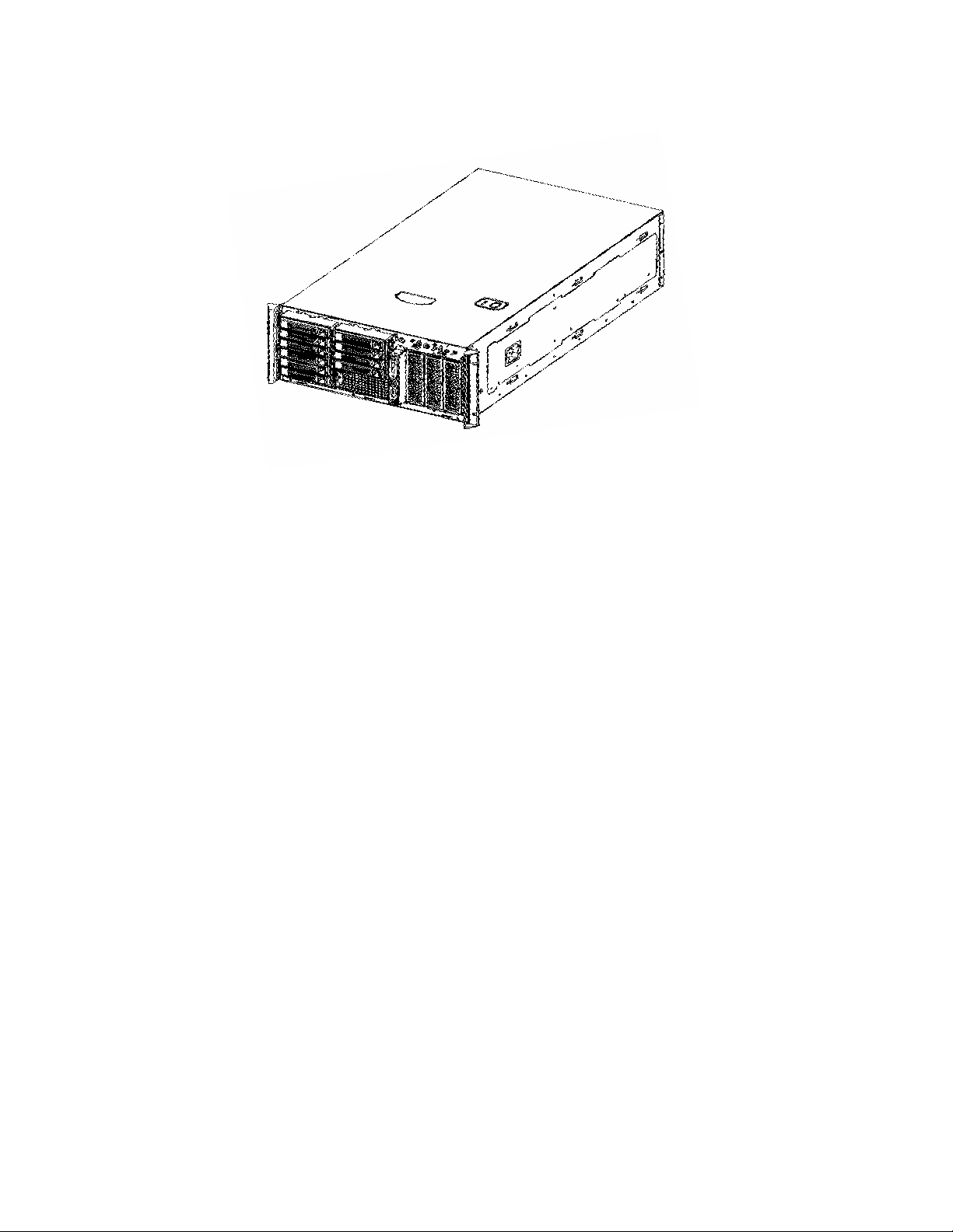
This specification details the feature set of the Intel® Server Chassis SC5300, an entry-level
server chassis designed for Intel
®
server board products. The Server Chassis SC5300 series of
products are low cost, quick to integrate, and allow utilization of multiple platforms and
configurations. The Server Chassis SC5300 series comes in three configurations: 600-W
SC53000BASE, 730-W SC5300BRP, and 730-W SC5300LX. The configurations are
distinguishable from one another based primarily on power supply and cooling features.
1.1 Intel® Server Chassis SC5300 Design Features
The Intel® Server Chassis SC5300 series makes extensive use of tool-less hardware features
and, dependent upon configuration and upgrade features, provides redundant cooling and
redundant power supply capability. The following table lists the features for the SC5300BASE,
SC5300BRP, and SC5300LX configurations.
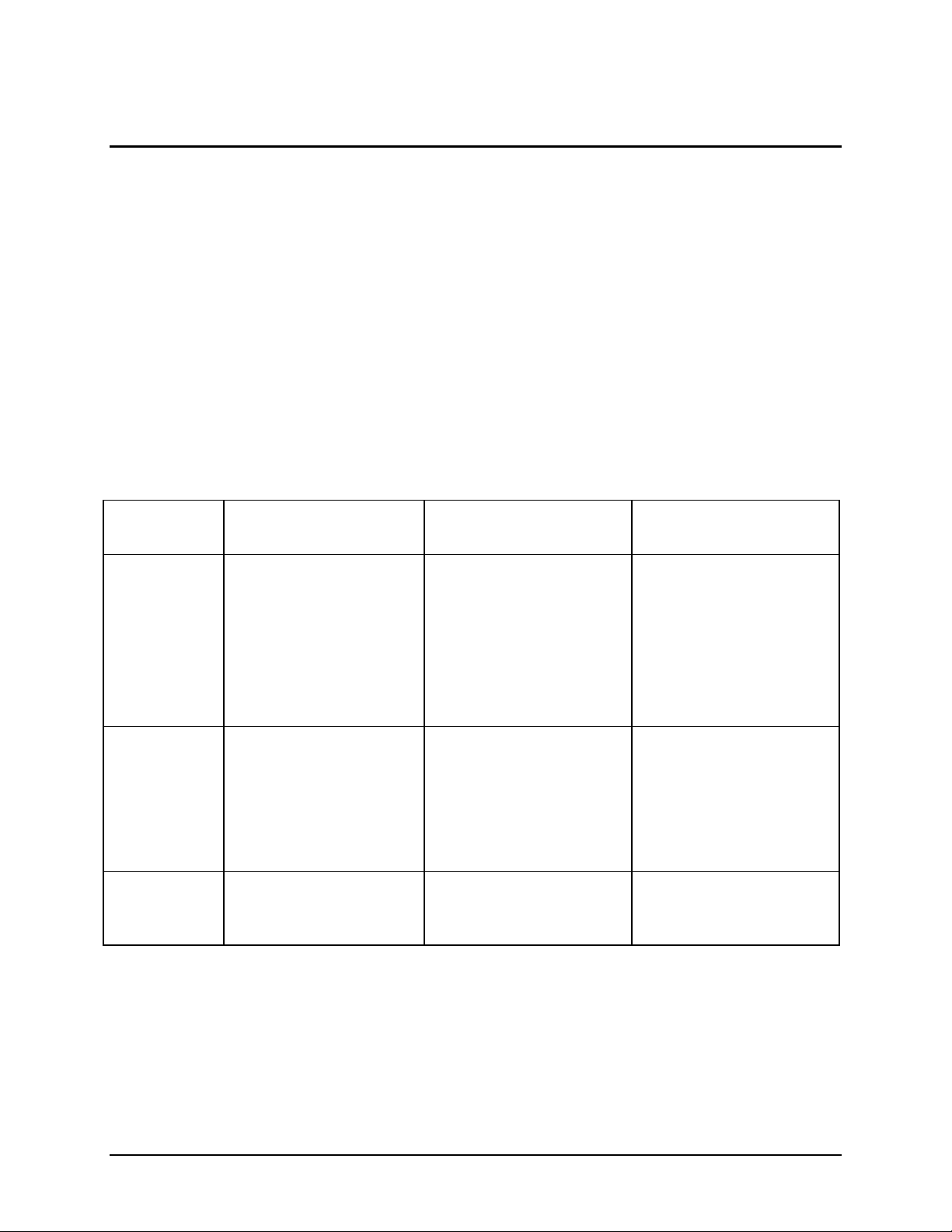
Table 1. Intel® Server Chassis SC5300BASE, SC5300BRP, and SC5300LX Features
Intel® Server Chassis
SC5300BASE
Power
Delivery
Includes one (1) fixed
600-W power factor
corrected (PFC) Intel
validated power supply
unit (PSU) with an
integrated cooling fan,
upgradeable to a
redundant (1+1) 730-W
PFC PSU
Intel® Server Chassis
SC5300BRP
Includes (1 of 2) redundant
730-W PFC module Intel
validated PSU. Each power
module includes an
integrated cooling fan.
Each redundant power
module includes one (1)
AC line input.
Intel® Server Chassis
SC5300LX
Includes (1 of 2) redundant
730-W PFC module Intel
validated PSU. Each power
module includes an
integrated cooling fan.
Each redundant power
module includes one (1)
AC line input.
System
Cooling
Peripheral
Bays
12 Revision 1.31
Two fixed, non-redundant
chassis fans: one (1) 120mm and one (1) 92-mm.
Upgradeable to redundant
cooling with optional
accessory kit. Both fans
are tool-less.
Three (3) tool-less, multimount 5.25-inch
peripheral bays
Two fixed, non-redundant
chassis fans: one (1) 120mm and one (1) 9-mm.
Upgradeable to redundant
cooling with optional
accessory kit. Both fans
are tool-less
Three (3) tool-less, multimount 5.25-inch peripheral
bays
Four tool-less, hot
swappable and redundant
chassis fans with handlemounted diagnostic failure
LEDs: two (2) 120-mm and
two (2) 92-mm.
Three (3) tool-less, multimount 5.25-inch peripheral
bays
Page 14
Intel® Server Chassis SC5300 5U Kit TPS Introduction
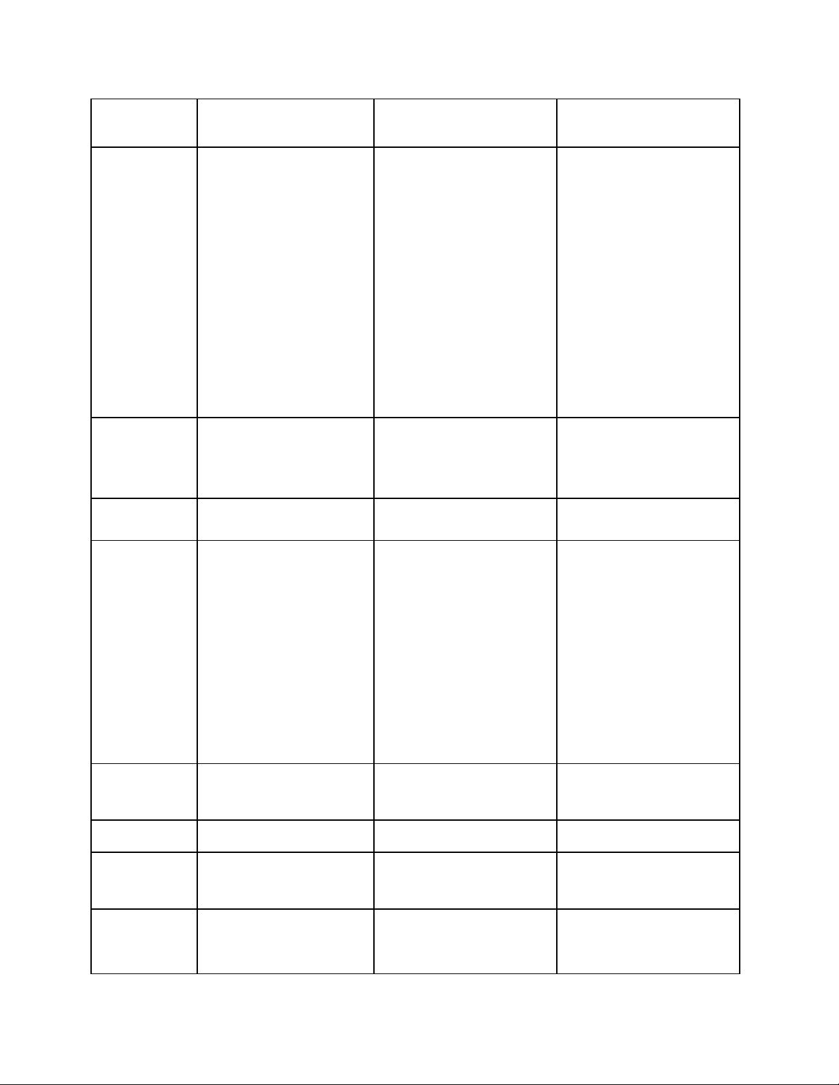
Intel® Server Chassis
SC5300BASE
Drive Bays
(6+4) Bay
Layout
PCI Slots
Form Factor
Includes one (1) tool-less
fixed drive bay for up to
six (6) fixed IDE or SCSI
drives.
Optional hot-swap / toolless drive bays available:
six-drive SCSI, six-drive
SATA/SAS, 4-drive SCSI.
A four-drive tool-less fixed
drive bay is also available
as an accessory
The SC5300BASE
configuration supports up
to six drives.
Seven full-length PCI slots Seven full-length PCI slots Seven full-length PCI slots.
5U Tower, convertible to
rack mount
Intel® Server Chassis
SC5300BRP
Includes one (1) tool-less
fixed drive bay for up to six
(6) fixed IDE or SCSI
drives.
Optional hot-swap / toolless drive bays available:
six-drive SCSI, six-drive
SATA/SAS, four-drive
SCSI.
A (4) drive tool-less fixed
drive bay is also available
as an accessory
The SC5300BRP
configuration supports up
to 10 drives
5U Tower, convertible to
rack mount
Intel® Server Chassis
SC5300LX
Includes one (1) tool-less
fixed drive bay for up to six
(6) fixed IDE or SCSI
drives.
Optional hot-swap / toolless drive bays available:
six-drive SCSI, six-drive
SATA/SAS, four-drive
SCSI.
A (4) drive tool-less fixed
drive bay is also available
The SC5300LX
configuration supports up
to 10 drives
Optional hot plug PCI kit is
available for the Intel®
Server Board SE7520AF2.
5U Tower, convertible to
rack mount
Front Panel
External
Color
Construction
Chassis ABS
LEDs for NIC1, NIC2,
System ID, HDD activity /
failure and system status.
Power Switch - ID switch,
Reset, Power, Sleep, NMI
Optical side cover
intrusion switch and
connection for bezel
intrusion switch
Integrated temperature
sensor for fan speed
management
Two (2) front USB and
one (1) optional front or
rear mounted serial port
Black Black Black
1.0 mm, zinc plated sheet
metal, meets Intel
Cosmetic Spec # C25432
Fire retardant, nonbrominated
LEDs for NIC1, NIC2,
System ID, HDD activity /
failure and system status.
Power Switch - ID switch,
Reset, Power, Sleep, NMI
Optical side cover intrusion
switch and connection for
bezel intrusion switch
Integrated temperature
sensor for fan speed
management
Two (2) front USB and one
(1) optional front or rear
mounted serial port
1.0 mm, zinc plated sheet
metal, meets Intel
Cosmetic Spec # C25432
Fire retardant, nonbrominated
PC-ABS
PC-ABS
Revision 1.31
PC-ABS
13
Page 15
Introduction Intel® Server Chassis SC5300 5U Kit TPS
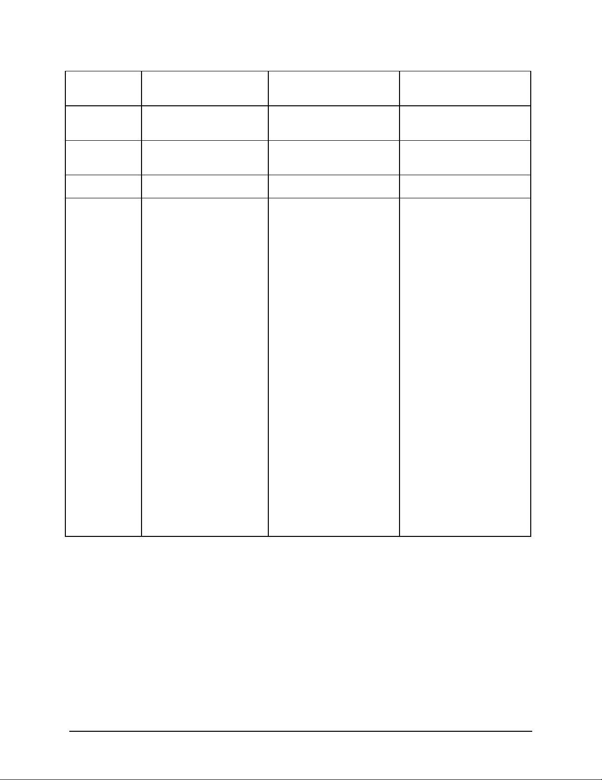
Intel® Server Chassis
SC5300BASE
Dimensions
(Rack)
Dimensions
(Pedestal)
Weight
Optional
Accessories
17.5-inch x 8.6-inch x
26.2-inch
17.5-inch x 8.6-inch x
26.9-inch
34.6 kg 36.2 kg 36.2 kg
Rack Conversion Kit
Rack Cable Management
Arm
Intel® Management
Module
Slim-line CD and Floppy
Carrier
Redundant Power Supply
Kit
Six (6) Drive Hot-swap
SCSI Backplane
Six (6) Drive Hot-swap
SATA.SAS backplane
Intel® Server Chassis
SC5300BRP
17.5-inch x 8.6-inch x
26.2-inch
17.5-inch x 8.6-inch x
26.9-inch
Rack Conversion Kit
Rack Cable Management
Arm
Intel® Management
Module
Slim-line CD and Floppy
Carrier
Redundant Power Supply
Kit
Six (6) Drive Hot-swap
SCSI Backplane
Six (6) Drive Hot-swap
SATA/SAS Backplane
Intel® Server Chassis
SC5300LX
17.5-inch x 8.6-inch x
26.2-inch
17.5-inch x 8.6-inch x
26.9-inch
Rack Conversion Kit
Rack Cable Management
Arm
Intel® Management
Module
Slim-line CD and Floppy
Carrier
Redundant Power Supply
Kit
Six (6) Drive Hot-swap
SCSI Backplane
Six (6) Drive Hot-swap
SATA/SAS Backplane
Four (4) Drive Hot-swap
SCSI Backplane
Redundant Cooling
Upgrade Kit
10-pack Branding /
Customization Panels
Four (4) Drive Fixed Drive
Bay
Unpainted Rack Top
Cover
Four (4) Drive Hot-swap
SCSI Backplane
Redundant Cooling
Upgrade Kit
10-pack Branding /
Customization Panels
Four (4) Drive Fixed Drive
Bay
Unpainted Rack Top Cover
Four (4) Drive Hot-swap
SCSI Backplane
Redundant Cooling
Upgrade Kit
10-pack Branding /
Customization Panels
Four (4) Drive Fixed Drive
Bay
Unpainted Rack Top Cover
Hot-plug PCI Kit
1.2 Intel® Server Chassis SC5300BASE Summary
The Intel® Server Chassis SC5300BASE is designed to address the entry-level market. It
includes a fixed single 600-W Power Factor Correction (PFC) non-redundant power supply,
which supports up to six hard drives. Two tachometer output fans are mounted in front of the
server board. Optional four- and six-drive SCSI hot swap drive bay kits provide upgrades to
allow support for 6 hot swap SCSI drives. An optional six-drive hot swap SATA/SAS drive bay
is also available. Three 5.25-inch half-height peripheral bays are available for installation of a
floppy drive, CD-ROM drive and/or other accessories. Standard chassis configuration is
pedestal. A rack mount conversion kit is available.
14 Revision 1.31
Page 16

Intel® Server Chassis SC5300 5U Kit TPS Introduction
1.3 Intel® Server Chassis SC5300BRP Summary
The Intel® Server Chassis SC5300BRP supports the redundant power capability of the
SC5300LX configuration and the fixed fan features of the SC5300BASE configuration. The
SC5300BRP configuration includes a single 730-W PFC power supply module. Two
tachometer output fans are mounted in front of the server board. When populating the server
chassis with a single power supply, the power supply must be populated in the first power
supply bay. A second 730-W module may be added to provide redundant power supply.
Optional four- and six-drive SCSI hot swap drive bay kits provide upgrades to allow support for
up to 10 hot swap SCSI drives. An optional six-drive hot swap SATA/SAS drive bay is also
available. Three 5.25-inch half-height peripheral bays are available for installations of a floppy
drive, CD-ROM drive and/or other accessories.
1.4 Intel® Server Chassis SC5300LX Summary
The Intel® Server Chassis SC5300LX supports redundant power and includes redundant fan
features. The SC5300LX configuration includes a single 730-W PFC power supply module.
When populating the server chassis with a single power supply, the power supply must be
populated in the first power supply bay. A second 730-W module may be added to provide
redundant power supply. Four LED hot swap tachometer output fans provide redundant
cooling. Optional four- and six-drive SCSI hot swap drive bay kits provide upgrades to allow
support for up to 10 hot swap SCSI drives. An optional six-drive hot swap SATA/SAS drive bay
is also available. Three 5.25-inch half-height peripheral bays are available for installation of a
floppy drive, CD-ROM drive and/or other accessories. The standard chassis configuration is
pedestal. A rack mount conversion kit is available.
Product Code Intel
Server
Board
SC5300BASE
Fixed 600-W
SC5300BRP
Hot Swap
Redundant
730-W
SC5300LX
Hot Swap
SE7520AF2
SE7520BD2
SE7525SP2
SE7525GP2
SE7520AF2
SE7520BD2
SE7520AF2
SE7520BD2
Table 2. Product Matrix
®
Optional
Hot Swap
SCSI/SAT
A/SAS
Drives
6-SCSI
6-
SATA/SAS
4-SCSI
6-SCSI
6-
SATA/SAS
4-SCSI
6-SCSI or 6-6-drive bay
Standard
Fixed Hard
Drive Bays
6-drive bay
4-drive bay
optional
accessory
is available
6-drive bay
4-drive bay
optional
accessory
is available
4-drive bay
Power Supply and
Required Power
Cord Configuration
Fixed 600-W PFC
Requires one power
cord
One 730-W PFC
module installed.
Second power
module is optional.
Requires one power
cord per module.
One 730-W PFC
module installed.
Hot
Swap
Fans
No Pedestal is
No Pedestal is
Yes Pedestal is
Pedestal/
Rack
Standard.
Rack
Conversion
Kit is an
accessory.
Standard.
Rack
Conversion
Kit is an
accessory.
Standard.
Revision 1.31
15
Page 17

Introduction Intel® Server Chassis SC5300 5U Kit TPS
Redundant
730-W
SATA/SAS
4-SCSI
optional
accessory
is available
Second power
module is optional.
Requires one power
cord per module.
Rack
Conversion
Kit is an
accessory.
16 Revision 1.31
Page 18
Intel® Server Chassis SC5300 5U Kit TPS Chassis Features
2. Chassis Features
2.1 Chassis Dimensions and Weight
Shipping weights include packaging.
Complete systems configured with server board, accessories and hard disk drivers will have
varying weights.
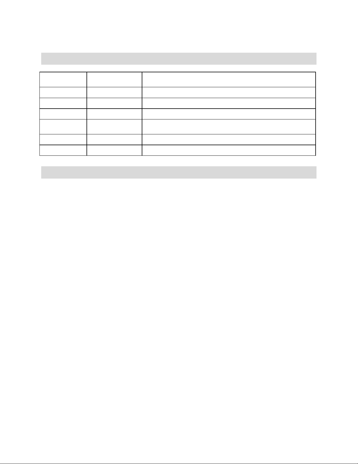
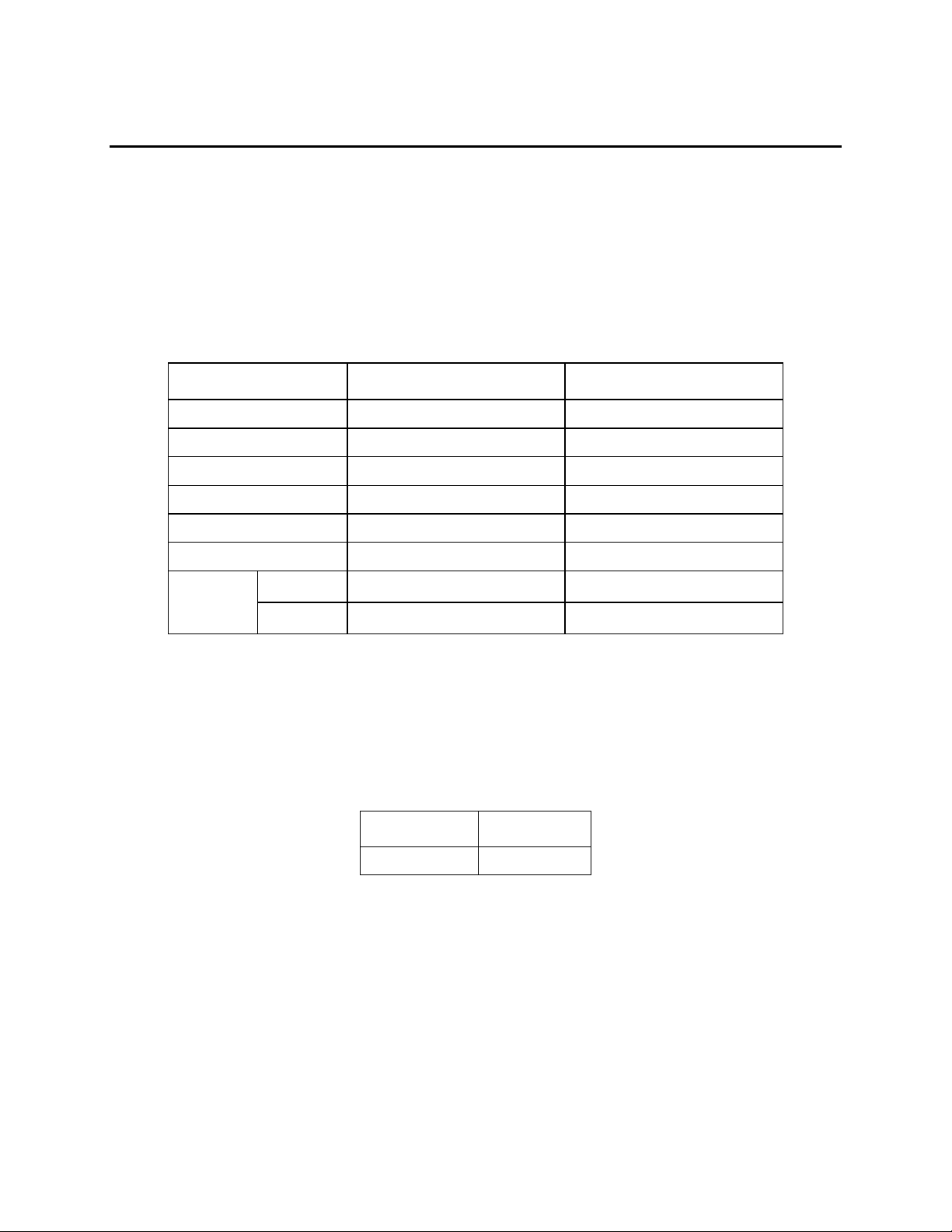
Table 3. Chassis Dimensions and Weights
Configuration Pedestal Rack
Height 17 inches (43.2 cm) 8.6 inches (21.8 cm)
Width 8.6 inches (21.8 cm) 16.5 inches (41.9 cm)
Depth 27.9 inches (70.9 cm) 27.4 inches (69.6 cm)
Clearance Front 10 inches (25.4 cm) N/A
Clearance Rear 5 inches (12.7 cm) N/A
Clearance Side 3 inches (7.6 cm) N/A
LX 36.2 kg 36.2 kg Weight
Base 34.6 kg 34.6 kg
2.2 System Colors
The Intel® Server Chassis SC5300 is offered in one color configuration, black.
Table 4. System Color Code
Manufacturer Color Code
GE Black GE701
2.2.1 Pedestal and Rack Mount Features
The standard pedestal front bezel is a molded plastic door covering all drive bays. A key lock is
provided to prevent unauthorized access to the peripheral bays. A molded plastic sub-bezel is
located on the face of the chassis under the front bezel. The sub-bezel houses the front panel
buttons and light pipes for the front panel indicators. Each peripheral bay is covered with a
removable electromagnetic interference (EMI) shield.
Opening the exterior plastic door on the pedestal chassis accesses the hot swap hard drives.
An EMI shield is incorporated into the drive carrier design, eliminating the need for a separate
Revision 1.31
17
Page 19
Chassis Features Intel® Server Chassis SC5300 5U Kit TPS
shield or door. This adds flexibility to the bezel design by making EMI performance independent
of the cosmetic plastic parts.
Customized bezels for OEM customers can be designed from the standard bezel design. OEM
snap-in branding panels are available.
In the rack mount configuration, the front door is removed and the sub-bezel becomes the front
panel for the rack mount system. The rack mount kit includes the chassis slides, rack handles,
front door hinge cover plate and intrusion switch modification hardware.
2.3 Security
A variety of chassis security options are provided at the system level:
1. A two-position key lock/switch will unlock the front bezel and side cover in the
pedestal configuration only. Rack mount configuration does not have a key lock.
2. For rack mounted systems, a removable padlock loop on the rear of the system
access cover can be used to prevent access to the microprocessors, memory, and
add-in cards. A variety of lock sizes can be accommodated by the 0.270-inch
diameter loop.
3. A Kensington* cable lock mounting hole is provided on the rear chassis I/O panel.
4. An intrusion switch for the side panel and front bezel door are standard. In the rack
mount configuration, only the system cover has an active intrusion switch. Note: See
the appropriate Server Board Technical Product Specification on the
support.intel.com website for a description of BIOS and Intel
security features. Intrusion switches are provided allowing server management
software, such as Intel
®
Server Management (ISM), to detect unauthorized access to
the system cover and pedestal bezel door.
®
Server Management
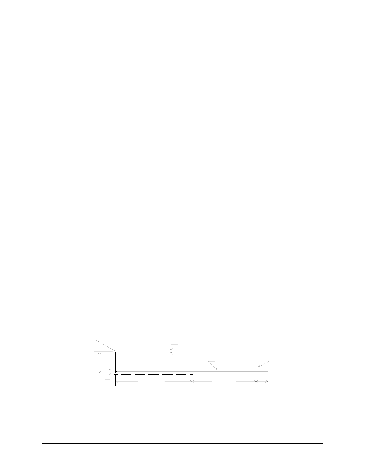
2.4 I/O Panel
All input/output (I/O) connectors are accessible on the rear of the chassis. The SSI E-bay 3.5compliant chassis provides an ATX* 2.03-compatible cutout for I/O shield installation. Boxed
server boards provide the required I/O shield for installation in the cutout. The I/O cutout
dimensions are shown in the following figure.
The rear I/O panel conforms to the Advanced Technology Extended (ATX) Specification,
Revision 2.1, and supports seven full-length expansion PCI adaptor cards.
R 0.039 MAX, TYP
1.750 ± 0.0 08
(0.150)
I/O Aperture
Figure 1. ATX* 2.03 I/O Aperture
0.100 Min keepout around opening
Baseboard
5.196 ± 0.0106.250 ± 0.008
Datum 0,0
(0.650)
18 Revision 1.31
Page 20
Intel® Server Chassis SC5300 5U Kit TPS Chassis Features
2.5 Standard and Optional Hot Swap Drive Bays
One fixed bay, supporting six cabled drives, ships with the standard chassis. An optional fourdrive bay for cabled (fixed) drives is available. Optional four- and six-drive hot swap bays are
also available and may be installed to replace either the six- or four-drive fixed bays. No tools
are required to replace the fixed drive bays. An optional six drive hot swap SATA/SAS bay is
also available. See the appendix for a full list of accessories.
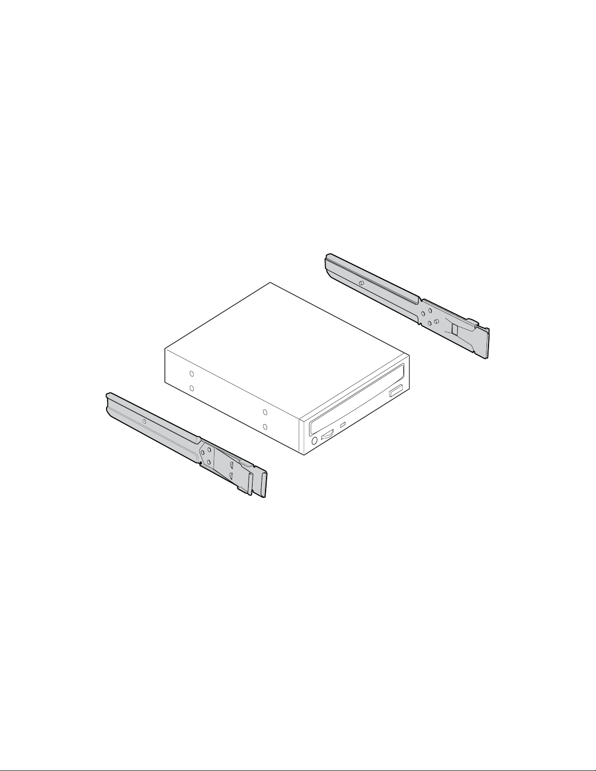
2.6 5.25-inch Half-height Peripheral Bays
Three 5.25-inch, half-height drive bays are available for installation of a floppy drive, CD-ROM
drive or tape drive. The chassis ships with a 3.5-inch floppy or fixed drive carrier installed in the
top 5.25-inch drive bay and two empty 5.25-inch drive bays. Tool-less mounting rails are
included for all three drive bays and attach without screws.
Figure 2. Tool-less Rails Mounting 5.25-inch CDROM Drive
Revision 1.31
TP00895
19
Page 21
Chassis Features Intel® Server Chassis SC5300 5U Kit TPS
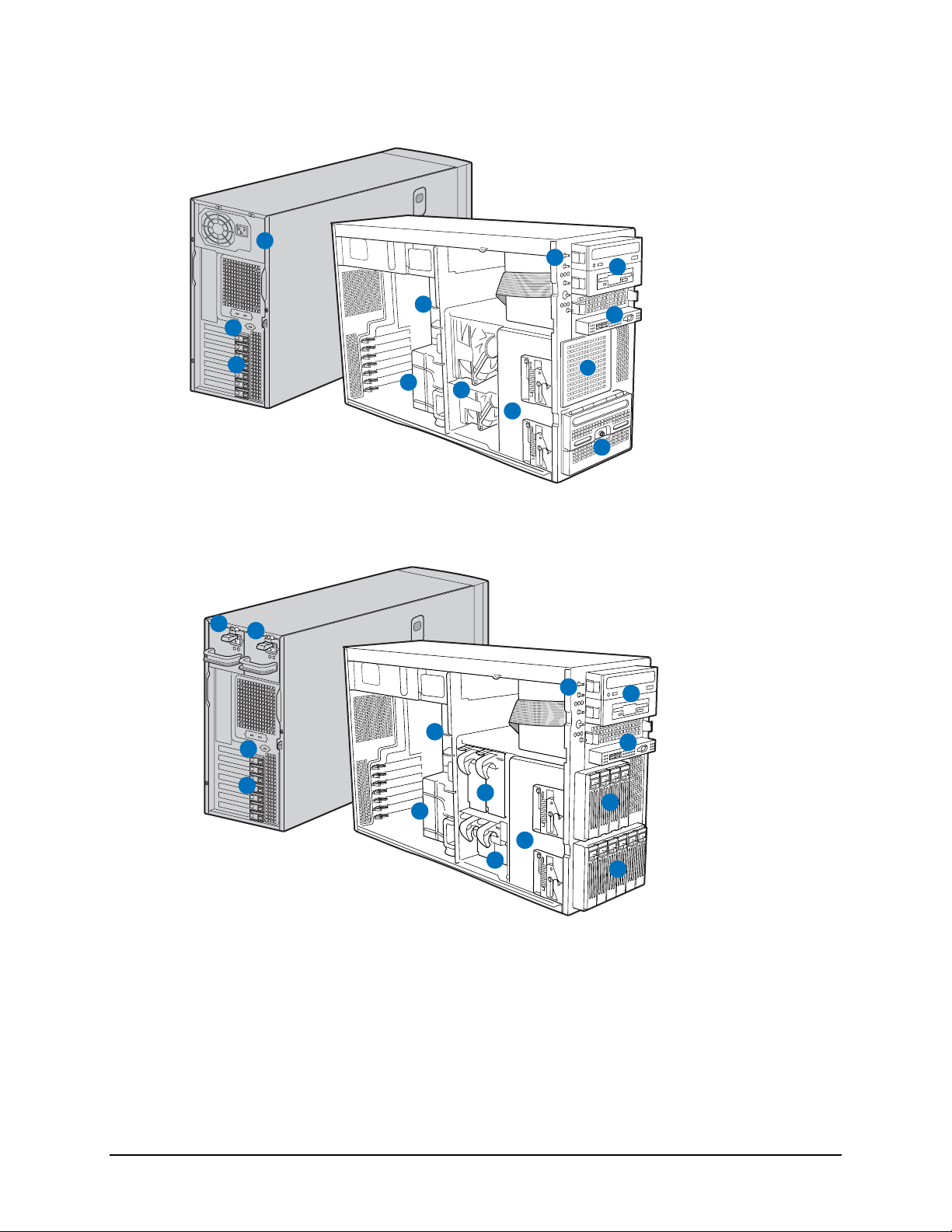
2.7 Chassis Views
1
12
2
Intel® Server Chassis
SC5300 with Base
Components
7
3
4
5
6
8
9
10
11
1. Fixed Power Supply
2. PCI Add-in Card Panel
3. Upper Air Duct
4. Lower Air Duct
5. Fixed Fans (2)
6. HDD Cage Release
Mechanisms (2)
7. Front Panel Control
8. 5.25" Device Bays (3)
9. Front Panel USB/Serial B
10. Fixed Drive Cage - 4 Drive
(accessory)
11. Fixed Drive Cage - 6 Drive
12. Rear Serial-B Connector
Figure 3. Intel® Server Chassis SC5300BASE Components
1
2
14
3
Intel® Server Chassis
SC5300 LX with Hot
Swap Components
TP00901
1. Hot Swap Power Supply
2. Second Hot Swap Power
Supply (accessory)
3. PCI Add-in Card Panel
4. Upper Air Duct
5. Lower Air Duct
6. Hot Swap Fans - Large (2)
9
4
6
5
10
11
12
7. Hot Swap Fans - Small (2)
8. HDD Cage Release
Mechanisms (2)
9. Front Panel Control
10. 5.25" Device Bays (3)
11. Front Panel USB/Serial B
12. Hot Swap Drive Cage - 4 Drive
(accessory)
13. Hot Swap Drive Cage - 6 Drive
14. Rear Serial-B Connector
8
7
13
TP00900
Figure 4. Intel® Server Chassis SC5300LX Components
20 Revision 1.31
Page 22
Intel® Server Chassis SC5300 5U Kit TPS Chassis Features
Figure 5. Rack Configuration with Sub-bezel and Right Side Panel Removed
Revision 1.31
21
Page 23

Chassis Power Subsystem Intel® Server Chassis SC5300 5U Kit TPS
3. Chassis Power Subsystem
The Server Chassis SC5300 power supplies are Server System Infrastructure (SSI) compliant.
The SSI specifications may be found at the following website:
W and 730-W power supplies have identical power supply wire harness cable lengths to
peripheral bays and server board.
3.1 600-W Power Supply
The 600-W power supply has eight outputs: 3.3V, 5V, 12V1, 12V2, 12V3, 12V4, -12V, and 5Vsb
(standby). The 600-W power supply contains a single 80-mm fan for cooling the power supply,
which also provides part of the system cooling. The 12V six-pin power connector is for the 150W PCI-E (video) cards, which require an external 75-W power connector.
3.1.1 Mechanical Outline
The power supply size is 150mm x 180mm x 86mm and has a wire harness for the DC outputs.
The AC power cord plugs directly into the external face of the power supply.
www.ssifourm.org. Both the 600-
22 Revision 1.31
Page 24
Intel® Server Chassis SC5300 5U Kit TPS Chassis Power Subsystem
Note: All dimensions are in mm.
3.1.2 Output Wire Harness
Listed or recognized component appliance wiring material (AVLV2), CN, rated min 105°C,
300VDC shall be used for all output wiring. Cable length, connector number and description are
identical for both the 600-W and 730-W power supplies.
Revision 1.31
23
Page 25

Chassis Power Subsystem Intel® Server Chassis SC5300 5U Kit TPS
Table 5. 600-W and 730-W Power Supply Cable Lengths
From
Power Supply cover exit
hole
Power Supply cover exit
hole
Power Supply cover exit
hole
Power Supply cover exit
hole
Power Supply cover exit
hole
Extension 100 P4 4 Peripheral Power Connector
Extension from P4 100 P5 4 Floppy Power Connector
Power Supply cover exit
hole
Extension
Power Supply cover exit
hole
Length
(mm)
425 P1 24 Baseboard Power Connector
375 P2 8 Processor Power Connector
375 P14 5 Power Signal Connector
375 P15 6 PCI Express Connector
450 P3 4 Peripheral Power Connector
575 P6 4 Peripheral Power Connector
75 (cover
with sleeve)
740
To
connector
#
P7 4
P8 4 Peripheral Power Connector
Number
of pins
Description
Right-angle Peripheral
Power Connector
Extension 75 P9 4 Peripheral Power Connector
Power Supply cover exit
hole
Extension 75 P11 4 Peripheral Power Connector
Power Supply cover exit
hole
Extension 75 P13 5 SATA Power Connector
740
740
P10 4 Peripheral Power Connector
P12 5
Right-angle SATA Power
Connector
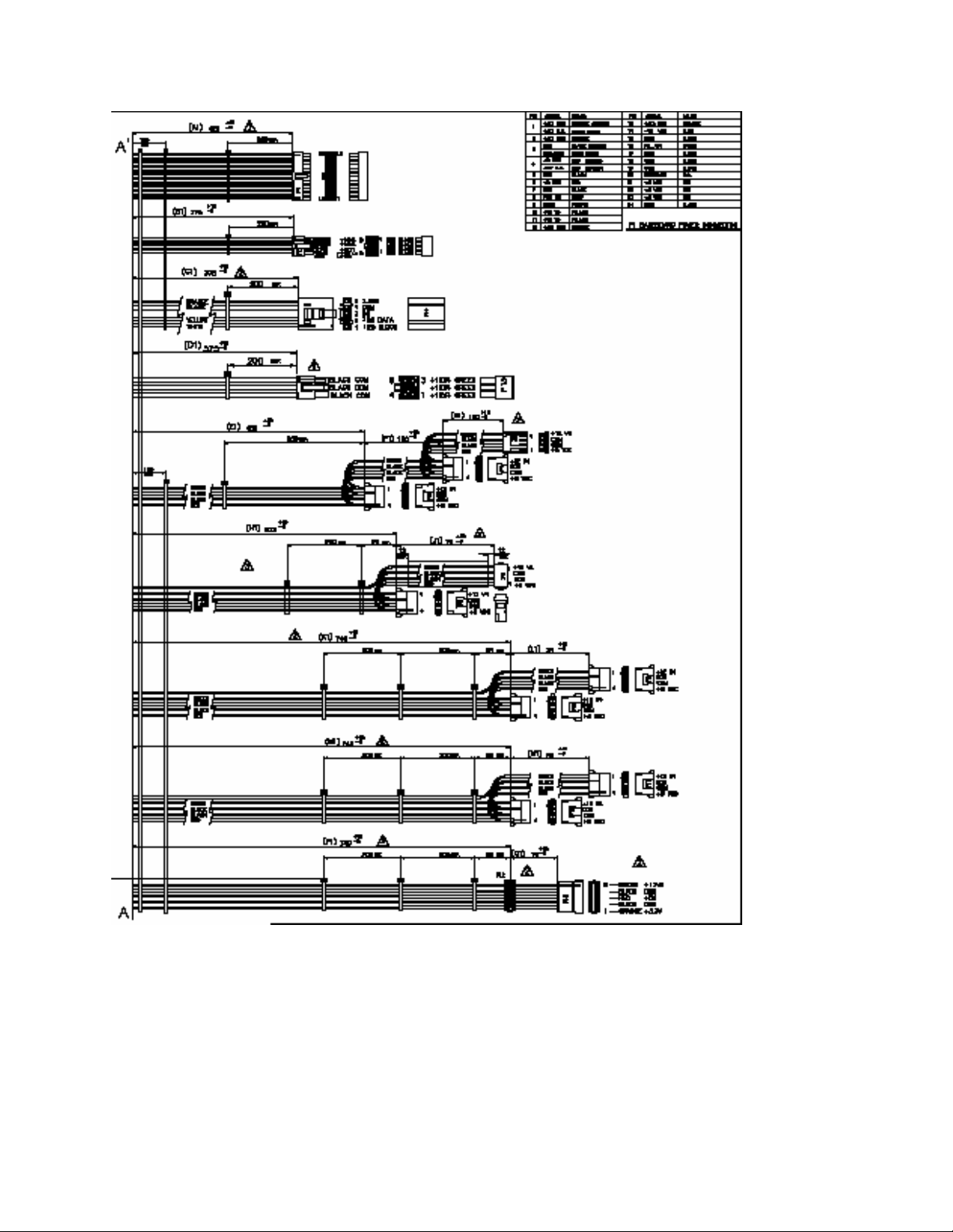
The output cable harness and connectors is detailed in the following figure.
24 Revision 1.31
Page 26
Intel® Server Chassis SC5300 5U Kit TPS Chassis Power Subsystem
Notes: (1) All dimensions are in mm. (2) All tolerances are +15-0mm. 3. (3) Install 1 tie wrap within 12 mm of PSU
case. (4) Mark reference designator on each connector. (5) Tie wrap each harness at approximately mid point or
point shown.
Figure 6. Output Cable Harness for 600-W and 700-W Power Supplies
Revision 1.31
25
Page 27
Chassis Power Subsystem Intel® Server Chassis SC5300 5U Kit TPS
3.1.2.1 Baseboard power connector (P1)
Connector housing: 24-Pin Molex* Mini-Fit Jr. 39-01-2245 or equivalent
Contact: Molex Mini-Fit, HCS, Female, Crimp 44476 or equivalent
Table 6. Baseboard Power Connector P1 Pin-out
Pin Signal 18 AWG Color Pin Signal 18 AWG Color
1* +3.3VDC Orange 13 +3.3VDC Orange
3.3V RS Orange (24AWG) 14 -12VDC Blue
2 +3.3VDC Orange 15 COM Black
3* COM Black 16 PSON# Green
COM RS Black (24AWG) 17 COM Black
4* +5VDC Red 18 COM Black
5V RS Red (24AWG) 19 COM Black
5 COM Black 20 Reserved N.C.
6 +5VDC Red 21 +5VDC Red
7 COM Black 22 +5VDC Red
8 PWR OK Gray 23 +5VDC Red
9 5 VSB Purple 24 COM Black
10 +12V3 Yellow
11 +12V3 Yellow
12 +3.3VDC Orange
* Remote Sense wire double crimped.
3.1.2.2 Processor Power Connector (P2)
Connector housing: 8-Pin Molex 39-01-2080 or equivalent
Contact: Molex 44476-1111 or equivalent
Table 7. Processor Power Connector P2
Pin Signal 18 AWG color Pin Signal 18 AWG Color
1 COM Black 5* +12V1 White
2 COM Black 12V1 RS Yellow (24AWG)
3 COM Black 6 +12V1 White
4 COM Black 7 +12V2 Brown
8* +12V2 Brown
26 Revision 1.31
Page 28
Intel® Server Chassis SC5300 5U Kit TPS Chassis Power Subsystem
Pin Signal 18 AWG color Pin Signal 18 AWG Color
12V2 RS Yellow (24AWG)
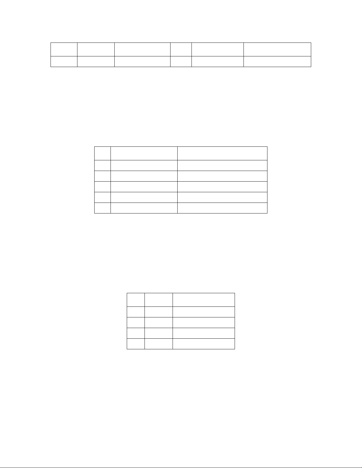
3.1.2.3 Power Signal Connector (P13)
Connector housing: 5-pin Molex 50-57-9405 or equivalent
Contacts: Molex 16-02-0087 or equivalent
Table 8. Power Signal Connector P13
Pin Signal 24 AWG Color
1 I2C Clock White
2 I2C Data Yellow
3 Reserved N.C.
4 COM Black
5 3.3RS Orange
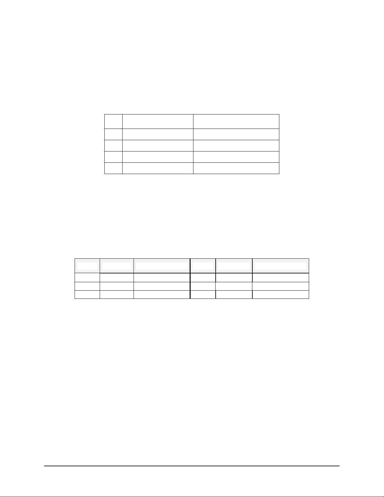
3.1.2.4 Peripheral Power Connectors (P3, P4, and P6, P8 – P11)
Connector housing: Amp 1-480424-0 or equivalent
Contact: Amp 61314-1 contact or equivalent
Table 9. Peripheral Power Connectors
Pin Signal 18 AWG Color
1 +12V4 Green
2 COM Black
3 COM Black
4 +5 VDC Red
Revision 1.31
27
Page 29
Chassis Power Subsystem Intel® Server Chassis SC5300 5U Kit TPS
3.1.2.5 Floppy Power Connector (P6)
Connector housing: Amp 171822-4 or equivalent
Contact: Amp 170204-1 contact or equivalent
Table 10. Floppy Power Connector P6
Pin Signal 22 AWG Color
1 +5VDC Red
2 COM Black
3 COM Black
4 +12V4 Green
3.1.2.6 PCI Express Connector (P15)
Connector housing: 6-pin Molex 39-01-2065 or equivalent
Contacts: Molex Mini-Fit, HCS, Female, Crimp 44476
Table 11. PCI Express Connector
PIN SIGNAL 18 AWG Colors PIN SIGNAL 18 AWG Colors
1 +12V4 Green 4 COM Black
2 +12V4 Green 5 COM Black
3 +12V4 Green 6 COM Black
3.1.3 600-W Power Supply Airflow and Temperature Rise
The power supply incorporates one 80-mm fan for self-cooling and system cooling. The fan
provides 14 CFM airflow through the power supply when installed in the system. The cooling air
enters the power module from the non-AC side.
The power supply meets UL enclosure requirements for temperature rise limits. All sides of the
power supply, with exception to the air exhaust side, are classified as “Handle, knobs, grips,
etc., held for short periods of time only.”
3.1.4 AC Specifications
The power supply incorporates universal power input with active power factor correction, which
reduces line harmonics in accordance with the EN61000-3-2 and JEIDA MITI standards.
28 Revision 1.31
Page 30

Intel® Server Chassis SC5300 5U Kit TPS Chassis Power Subsystem
3.1.4.1 AC Inlet Connector
The AC input connector is an IEC 320 C-14 power inlet. This inlet is rated for 10A / 250VAC.
3.1.4.2 AC Input Voltage Specification
The power supply operates within all specified limits over the following input voltage range (see
the following table). The power supply shall power off if the AC input is less than 75-80VAC
ranges. The power supply operates properly starting at 80-85VAC input voltages.
Table 12. AC Input Ratings
I
PARAMETER MIN RATED V
MAX
MAX
Voltage (110) 90 V
100-127
rms
V
rms
Voltage (220) 180 Vrms 200-240
V
rms
140 V
264 V
10 A
rms
5 A
rms
1, 3
2, 3
Frequency 47 Hz 50/60 63 Hz
Start up
VAC
85VAC +/4VAC
Power Off
VAC
75VAC +/5VAC
Notes:
(1) Maximum input current at low input voltage range shall be measured at 90VAC, at max load.
(2) Maximum input current at high input voltage range shall be measured at 180VAC, at max load.
(3) This requirement is not to be used for determining agency input current markings.
3.1.4.3 Efficiency
The 600-W power supply has an efficiency of 68% at maximum load and over the specified AC
voltage.
3.1.4.4 AC Line Dropout / Holdup
An AC line dropout occurs when the AC input drops to zero VAC at any phase of the AC line for
any length of time. During an AC dropout of one cycle or less, the power supply meets dynamic
voltage regulation requirements over the rated load. An AC line dropout of 1 cycle or less (20
ms min) shall not cause any tripping of control signals or protection circuits. If the AC dropout
lasts longer than one cycle, the power supply should recover and meet all turn-on requirements.
The power supply meets the AC dropout requirement over rated AC voltages, frequencies, and
output loading conditions. Any dropout of the AC line does not cause damage to the power
supply.
3.1.4.5 AC Line Fuse
The power supply has one line fused in the single line fuse on the line (hot) wire of the AC input.
The input fuse is a slow blow type. AC inrush current does not cause the AC line fuse to blow
under any conditions. Not all protection circuits shall cause the AC fuse to blow unless a
component in the power supply has failed. This includes DC output load short conditions.
Revision 1.31
29
Page 31

Chassis Power Subsystem Intel® Server Chassis SC5300 5U Kit TPS
3.1.5 600-W DC Output Specifications
3.1.5.1 Grounding
The output ground of the pins of the power supply provides the return path. The output
connector ground pins is to the safety ground (power supply enclosure).
3.1.5.2 Output Voltage and Currents
The following tables define two power and current ratings for the 600-W power supply. The
combined output power of all outputs shall not exceed the rated output power.
Table 13. Maximum System Load Ratings
Voltage
Minimum
Continuous
Load
Maximum
Continuous Load
1, 3
Peak Load
+3.3V6 1.5 A 20 A
6
+5V
5.0 A 24 A
+12V1 1.5 A 15 A 18 A
+12V2 1.5 A 15 A 18 A
+12V3 1.5 A 16 A 18 A
+12V4 1.5 A 16 A 18 A
-12V 0 A 0.5 A
+5VSB 0.1 A 2.0 A
Table 14. Light System Load Ratings
Voltage Minimum
Continuous Load
Maximum
Continuous Load
Peak Load
+3.3V6 0.5 A 9.0 A
6
+5V
2.0 A 7.0 A
2, 4, 5
5
+12V1 0.5 A 5.0 A 7.0 A
+12V2 0.5 A 5.0 A 7.0 A
+12V3 2.0 A 6.0 A
+12V4 0.5 A 5.0 A
-12V 0 A 0.5 A
+5VSB 0.1 A 2.0 A
Notes:
(1) Maximum continuous total DC output power should not exceed 600 W.
30 Revision 1.31
Page 32

Intel® Server Chassis SC5300 5U Kit TPS Chassis Power Subsystem
(2) Peak load on the combined 12V output shall not exceed 48A.
(3) Maximum continuous load on the combined 12V output shall not exceed 43A.
(4) Peak total DC output power should not exceed 660W.
(5) Peak power and peak current loading shall be supported for a minimum of 12 seconds.
3.1.5.3 Voltage Regulation
The output voltages must stay within the following voltage limits when operating at steady state
and dynamic loading conditions. These limits include the peak-peak ripple/noise. All outputs are
measured with reference to the return remote sense signal (ReturnS). The +12V3, +12V4, –12V
and 5VSB outputs are measured at the power supply connectors referenced to ReturnS. The
+3.3V, +5V, +12V1, and +12V2 are measured at the remote sense signal located at the signal
connector.
Table 13. Voltage Regulation Limits
PARAMETER TOLERANCE MIN NOM MAX UNITS
+3.3V - 5% / +5% +3.14 +3.30 +3.46 V
+5V - 5% / +5% +4.75 +5.00 +5.25 V
+12V1 - 5% / +5% +11.40 +12.00 +12.60 V
+12V2 - 5% / +5% +11.40 +12.00 +12.60 V
+12V3 - 5% / +5% +11.40 +12.00 +12.60 V
+12V4 - 5% / +5% +11.40 +12.00 +12.60 V
- 12V - 5% / +9% - 11.40 -12.00 -13.08 V
+5VSB - 5% / +5% +4.75 +5.00 +5.25 V
rms
rms
rms
rms
rms
rms
rms
rms
3.1.5.4 Standby Operation
The 5V standby output is present when an AC input greater than the power supply turn on
voltage is applied.
The power supply fan is off (fan-less operation) when the power supply is in the stand-by mode
of operation. The power supply will work indefinitely in stand-by mode with the input AC power
on, power supply off, and the 5V stand-by output at full load (=2A).
3.1.6 600-W Protection Circuits
Protection circuits inside the power supply shall cause only the power supply’s main outputs to
shutdown. If the power supply latches off due to a protection circuit tripping, an AC cycle OFF
for 15 sec and a PSON# cycle HIGH for 1 sec shall be able to reset the power supply.
Revision 1.31
31
Page 33

Chassis Power Subsystem Intel® Server Chassis SC5300 5U Kit TPS
3.1.6.1 Over Voltage Protection
The power supply shall shutdown and latch off after an over voltage condition occurs. The
voltage shall never exceed the maximum levels when measured at the power pins of the power
supply connector during any single point of fail. The voltage shall never trip any lower than the
minimum levels when measured at the power pins of the power supply connector. 5Vsb (standby) will be auto-recovered after removing the Over Voltage Protection limit.
3.1.6.2 Over Temperature Protection
In an over temperature condition, the power supply will shutdown. When the power supply
temperature drops to within specified limits, the power supply shall restore power automatically,
while the 5VSB remains always on. The over temperature protection circuit has built-in
hysterisis such that the power supply will not oscillate on and off due to a temperature
recovering condition. The over temperature protection trip level shall have a minimum of 4°C of
ambient temperature hysterisis.
3.1.7 600-W Power Supply Control and Indicator Functions
The following sections define the input and output signals from the power supply.
Signals that can be defined as low true use the following convention:
Signal# = low true
3.1.7.1 PSON# Input Signal
The PSON# signal is required for remotely turning on or off the power supply. PSON# is an
active low signal that turns on the +3.3V, +5V, +12V, and -12V power rails. When this signal is
not pulled low by the system, or left open, the outputs (except the +5VSB) turn off. This signal is
pulled to a standby voltage by a pull-up resistor internal to the power supply.
3.1.7.2 PWOK (Power OK) Output Signal
PWOK is a power OK signal and is pulled HIGH by the power supply to indicate that all the
outputs are within the regulation limits of the power supply. When any output voltage falls below
regulation limits or when AC power has been removed for a time sufficiently long so that power
supply operation is no longer guaranteed, PWOK will be de-asserted to a LOW state. The start
of the PWOK delay time shall be inhibited as long as any power supply output is in current limit.
3.1.8 Mean Time Between Failures (MTBF)
The power supply shall have a minimum MTBF at continuous operation of 100,000 hours at
80% load at 40°C, as calculated by Bellcore RPP, or 250,000 hours demonstrated at 80% load
°C.
at 40
3.2 730-W Power Supply
The 730W power supply replaceable module has two outputs: 12V and 5VSB. The input is
power factor corrected. An IEC connector on the external face provides for AC input to the
power supply. The power supply contains a cooling fan.
32 Revision 1.31
Page 34

Intel® Server Chassis SC5300 5U Kit TPS Chassis Power Subsystem
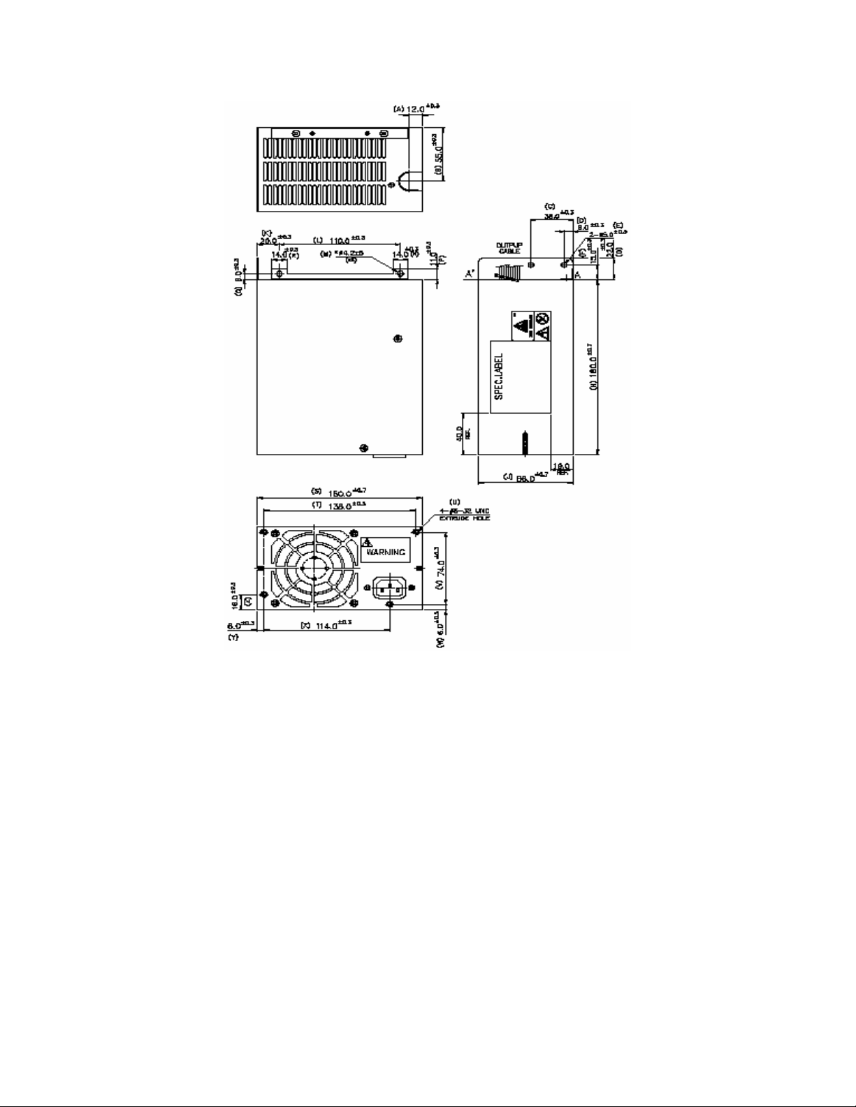
3.2.1 730W Power Supply Mechanical Outline
Figure 7. 730-W Power Supply Mechanical Drawings
Revision 1.31
33
Page 35

Chassis Power Subsystem Intel® Server Chassis SC5300 5U Kit TPS
3.2.2 Output Wire Harness
The output wiring harness is part of the power distribution board (backplane) and is described in
that section. The 730-W power supply wiring harness is identical to the 600-W power supply
described in Section
3.1.2 above.
3.2.3 Airflow Requirements and Temperature Rise
The power module supply incorporates one 80-mm fan. The fan will provide no less than 14
CFM airflow through the power supply when installed in the system
The power supply meets UL enclosure requirements for temperature rise limits. All sides of the
power supply, with exception to the air exhaust side, are classified as “Handle, knobs, grips,
etc., held for short periods of time only.”
3.2.4 AC Specifications
The power supply incorporates universal power input with active power factor correction, which
reduces line harmonics in accordance with the EN61000-3-2 and JEIDA MITI standards. The
AC input connector shall be an IEC 320 C-14 power inlet. This inlet is rated for 15A / 250VAC.
3.2.4.1 AC Input Voltage Specification
The power supply operates within all specified limits over the following input voltage range (see
the following table). The power supply shall power off if the AC input is less than the 75-80VAC
range. The power supply operates properly starting at 80-85VAC input voltages.
Table 15. AC Input Rating
PARAMETER MIN RATED MAX Max Input
Current
rms
rms
100-127 V
200-240 V
140 V
rms
264 V
rms
TBD A
rms
TBD A
rms
rms
rms
63 Hz
Voltage (110) 90
V
Voltage (220) 180
V
Frequency 47
Start up
Power Off
VAC
85Vac +/-
4Vac
75Vac +/5Vac
VAC
Hz
3.2.4.2 Efficiency
The power supply has a recommended minimum efficiency of 77% at maximum load and over
the specified AC voltage.
34 Revision 1.31
Page 36

Intel® Server Chassis SC5300 5U Kit TPS Chassis Power Subsystem
3.2.4.3 AC Line Fuse
The power supply shall have a single line fuse, on the line (hot) wire of the AC input. The input
fuse shall be a slow blow type. AC inrush current shall not cause the AC line fuse to blow under
any conditions. No protection circuits in the power supply shall cause the AC fuse to blow
unless a component in the power supply has failed. This includes DC output load short
conditions.
3.2.5 730-W DC Specifications
3.2.5.1 Output Module Edge Connector
The power supply provides card edge fingers, which mate to a female connector located on the
backplane (power distribution board). This blind mating type connector connects the power
supply’s output voltages and signals.
Table 16. Edge Finger Pin-out
Pin Component
side
31 GND 31 GND
30 GND 30 GND
29 GND 29 GND
28 GND 28 GND
27 GND 27 GND
26 GND 26 GND
25 +12V 25 +12V
24 +12V 24 +12V
23 +12V 23 +12V
22 +12V 22 +12V
21 +12V 21 +12V
20 +12V 20 +12V
19 +12V 19 +12V
18 +12V 18 +12V
17 +12V 17 +12V
Pin Bottom
16 +12V 16 +12V
15 +12V 15 +12V
14 +12V 14 +12V
13 GND 13 GND
12 GND 12 GND
11 GND 11 GND
Revision 1.31
35
Page 37

Chassis Power Subsystem Intel® Server Chassis SC5300 5U Kit TPS
Pin Component
side
10 GND 10 GND
9 GND 9 GND
8 GND 8 GND
7 Reserved 7 5VSB
6 PSKill 6 5VSB
5 PSON 5 Returns
4 PWOK 4 I2C SCL
3 SMBAlert 3 I2C SDA
2 +12LS 2 A0
1 Vbias 1 +12VRS
Pin Bottom
The ground of the pins of the output connector provides the power return path. The ground pin
is connected to safety ground (power supply enclosure).
3.2.5.2 Output Power / Currents
The following table defines the current ratings for the 730-W power supply.
Table 17. 730-W Load Ratings
Minimum
Voltage
+12V 3.0 A 60 A 70 A peak
+5VSB 0 A 2.0 A 2.5 A 10 W 15 W
Total continuous power (note 1) = 730 W
Total Peak power (note 2) = 855 W
Notes:
(1) Maximum continuous total DC output power should not exceed 730 watts.
(2) Peak power and peak current loading shall be supported for a minimum of 15 seconds.
Continuous
Load
Maximum
Continuous
Load
Peak Load
(see note
2)
Max
Continuous
Power
720 W 840 W
Max Peak
Power
3.2.5.3 Standby Outputs
The 5VSB output shall be present when an AC input greater than the power supply turn on
voltage is applied.
36 Revision 1.31
Page 38

Intel® Server Chassis SC5300 5U Kit TPS Chassis Power Subsystem
3.2.5.4 Stand By Operation
Fan-less operation requirement is the power supply’s ability to work indefinitely in stand-by
mode: with power on, power supply off and the 5VSB at full load (=2A) under environmental
conditions (temperature, humidity, altitude).
3.2.5.5 Voltage Regulation
The output voltages must stay within the following voltage limits when operating at steady state
and dynamic loading conditions. All outputs are measured with reference to the return remote
sense signal (ReturnS). The 12V and 5VSB outputs are measured at the power distribution
output connectors referenced to return source.
Table 18. Voltage Regulation Limits
Parameter Tolerance MIN NOM MAX Units
+ 12V -4%/+5% +11.52 +12.00 +12.60 V
+ 5VSB -4%/+5% +4.80 +5.00 +5.25 V
rms
rms
3.2.6 730-W Protection Circuits
Protection circuits inside the power supply shall cause only the power supply’s main output to
shutdown. If the power supply latches off due to a protection circuit tripping, an AC cycle OFF
for 15 sec and a PSON# cycle HIGH for 1 sec shall be able to reset the power supply.
3.2.6.1 Over Current Protection
The power supply shall have over current limit to prevent the +12V output. If the current limits
are exceeded, the power supply shall shutdown and latch off. The latch is cleared by toggling
the PSON# signal or by an AC power interruption. The power supply shall not be damaged from
repeated power cycling in this condition. The 5VSB shall also be protected during over current
or shorted conditions so that no damage can occur to the power supply.
3.2.6.2 Over Voltage Protection and Over Temperature
The power supply shall shutdown and latch off after an over voltage condition occurs. This latch
is cleared by toggling the PSON
#
signal or by an AC power interruption.
The power supply is protected against over temperature conditions caused by loss of fan
cooling or excessive ambient temperature. In an over temperature protection (OTP) condition
the power supply will shutdown. When the power supply temperature drops to within specified
limits, the power supply shall restore power automatically, while the 5VSB remains always on.
Revision 1.31
37
Page 39

Chassis Power Subsystem Intel® Server Chassis SC5300 5U Kit TPS
3.2.7 730-W Power Supply Control and Indicator Functions
3.2.7.1 PSON# Input Signal
The PSON# signal is required to turn on/off the power supply. PSON# is an active low signal
that turns on the +12V power rail. When this signal is not pulled low by the system, or left open,
the output (except the +5VSB) turns off. This signal is pulled to a standby voltage by a pull-up
resistor internal to the power supply.
3.2.7.2 PWOK Output Signal
PWOK is a power OK signal and is pulled HIGH by the power supply to indicate that all the
outputs are within the regulation limits of the power supply. When any output voltage falls below
regulation limits or when AC power has been removed for a time sufficiently long so that power
supply operation is no longer guaranteed, PWOK is de-asserted to a LOW state.
3.2.7.3 PSKILL Signal Requirements
The purpose of the PSKill pin is to allow for hot swapping of the power supply. The PSKill pin on
the power supply is shorter than the other signal pins. When a power supply is operating in
parallel with other power supplies and then extracted from the system, the PSKill pin will quickly
turn off the power supply and prevent arching of the DC output contacts.
3.2.8 730-W Mean Time Between Failure (MTBF)
The power supply shall have a minimum MTBF at continuous operation of 100,000 hours at
100% load and 45°C, as calculated by Bellcore RPP, or 250,000 hours demonstrated at 100%
load and 45°C.
3.2.9 Redundant (1+1) Hot Swap Mode
In the redundant (1+1) parallel configuration (two power supply modules installed) the +12V
output shared output current is enough current to meet voltage regulation limits during hot
swapping and power supply failures. Hot swapping a power supply is the process of inserting
and extracting a power supply from an operating power system while the AC cord is unplugged.
During this process, the output voltages shall remain within the limits specified. In general, a
failed supply may be removed and replaced with a good power supply. Hot swap works with
operational as well as failed power supplies. There is a mechanical latch on the power supply to
prevent the removal or insertion of a power supply while the AC power cord is plugged into the
power supply.
3.3 730-W Power Distribution Board
The power distribution board (PDB) is designed to plug directly to the output connector of the
power supplies and contains the DC/DC power converters required to produce the output
voltages: +3.3 VDC, +5 VDC and –12 VDC along with additional protection circuitry and a FRU
EEPROM.
38 Revision 1.31
Page 40

Intel® Server Chassis SC5300 5U Kit TPS Chassis Power Subsystem
3.3.1 Power Distribution Mechanical Overview
Note: All dimensions are in mm.
Figure 8. Enclosure Mechanical Dimensions
Revision 1.31
39
Page 41

Chassis Power Subsystem Intel® Server Chassis SC5300 5U Kit TPS
Figure 9. Mechanical Dimensions Power Distribution Board
Note: All dimensions in the drawing are in mm.
40 Revision 1.31
Page 42

Intel® Server Chassis SC5300 5U Kit TPS Chassis Power Subsystem
3.3.2 Temperature Operational Limits
The power supply modules provide airflow to cool the power distribution board. The power
distribution board operates over the specified limits listed in the following table.
Table 19. Thermal Requirements
Item Description MIN MAX Units
Top Operating temperature range. 0 40
T
Non-operating temperature range. -40 70
non-op
°C
°C
3.3.3 Electrical Specification
3.3.3.1 Input Connectors
Each connector provides card edge fingers, which mate with the female input connector on the
power distribution board. The female type connector on the power distribution board is a right
angle 2x31 pin type Singatron* (p/n: 2806-62-R-30T-P-K1) or equivalent.
Signals which are defined as low true or high true use the following convention:
signal# = low true
Reserved pins are reserved for future use.
Table 20. Cable Lengths
Length For
From
revision S0
only
Connector #
No of
pins
Description
(mm)
Power Supply cover exit
hole
Power Supply cover exit
hole
Power Supply cover exit
hole
Extension 100 P4 4
Power Supply cover exit
hole
Extension 100 P6 4
450 P1 24
450 P2 8
230 P3 4
350 P5 4
Baseboard Power
Connector
Processor Power
Connector
Peripheral Power
Connector
Peripheral Power
Connector
Peripheral Power
Connector
Floppy Power
Revision 1.31
41
Page 43

Chassis Power Subsystem Intel® Server Chassis SC5300 5U Kit TPS
Connector
Power Supply cover exit
hole
Extension
Power Supply cover exit
hole
Extension
Power Supply cover exit
hole
Extension 75 P12 4
Signal 450 P13 5 Signal Connector
550
75
550
75
550
P7 4
P8 4
P9 4
P10 4
P11 4
Peripheral Power
Connector
Peripheral Power
Connector
Peripheral Power
Connector
Peripheral Power
Connector
Peripheral Power
Connector
Peripheral Power
Connector
3.3.3.2 Baseboard Power Connector (P1)
Connector housing: 24-Pin Molex Mini-Fit Jr. 39-01-2245 or equivalent
Contact: Molex Mini-Fit, HCS, Female, Crimp 44476 or equivalent
Table 21. P1 Baseboard Power Connector
Pin Signal 18 AWG Color Pin Signal 18 AWG Color
1 +3.3VDC*+ Orange 13 +3.3VDC Orange
2 +3.3VDC Orange 14 -12VDC Blue
3 COM Black 15 COM Black
4 +5VDC* Red 16 PSON# Green
5 COM Black 17 COM Black
6 +5VDC Red 18 COM Black
7 COM Black 19 COM Black
8 PWR OK Gray 20 Reserved N.C.
9 5 VSB Purple 21 +5VDC Red
10 +12V3 Yellow 22 +5VDC Red
11 +12V3 Yellow 23 +5VDC Red
12 +3.3VDC Orange 24 COM Black
Notes: * Remote Sense wire double crimped
+ If the signal connector is not present, the 3.3V remote sense wire will be double crimped into pin 1 in the baseboard
power connector (P1)
42 Revision 1.31
Page 44

Intel® Server Chassis SC5300 5U Kit TPS Chassis Power Subsystem
3.3.3.3 Processor Power Connector (P2)
Connector housing: 8-Pin Molex 39-01-2080 or equivalent
Contact: Molex 44476-1111 or equivalent
Table 22. P2 Processor Power Connector
Pin Signal 18 AWG color Pin Signal 18 AWG Color
1 COM Black 5 +12V1 Yellow
2 COM Black 6 +12V1 Yellow
3 COM Black 7 +12V2 Yellow
4 COM Black 8 +12V2 Yellow
3.3.3.4 Peripheral Power Connectors (P3 - P5, P7 - P12)
Connector housing: Amp 1-480424-0 or equivalent;
Contact: Amp 61314-1 contact or equivalent
Table 23. P3-P5, P7-P12 Peripheral Power Connectors
Pin Signal 18 AWG Color
1 +12V4 Yellow
2 COM Black
3 COM Black
4 +5 VDC Red
3.3.3.5 Floppy Power Connector (P6)
Connector housing: Amp 171822-4 or equivalent;
Contact: Amp 170204-1 contact or equivalent
Table 24. P6 Floppy Power Connector
Pin Signal 22 AWG Color
1 +5VDC Red
2 COM Black
3 COM Black
Revision 1.31
43
Page 45

Chassis Power Subsystem Intel® Server Chassis SC5300 5U Kit TPS
Pin Signal 22 AWG Color
4 +12V4 Yellow
3.3.3.6 Power Signal Connector P13
Connector housing: 5-pin Molex 50-57-9405 or equivalent
Contacts: Molex 16-02-0087 or equivalent
Table 25. Power Signal Connector
Pin Signal 24 AWG Color
1 I2C Clock Brown
2 I2C Data Blue
3 SMBAlert# White
4 Return Sense Black
5 3.3RS Orange
3.3.3.7 12V Output Load Requirements
The +12V output power requirements from the power distribution board with a single or two
ERP12V 730-W power supplies plugged into the input of the power distribution board are as
follows.
Note: The combined total power limit for all outputs is 700-W max.
Table 26. +12V Outputs Load Ratings
MAX Load 14A 14A 16A 18A
MIN Static / Dynamic Load 0.5 0.5 1.5A 1.5A
Peak load 18A 18A 18A 22A
+12V1/2/3/4 combined output limit = 48A / 58Apk
+12V1 +12V2 +12V3 +12V4
Notes:
(1) Combined output power from the power distribution board shall not exceed 700W.
(2) Combined power on the 3.3V/5V rails shall not exceed 140W.
(3) Combined current on the +12V rails shall not exceed 48A.
(4) Combined peak power out of the power distribution board shall not exceed 825W.
44 Revision 1.31
Page 46

Intel® Server Chassis SC5300 5U Kit TPS Chassis Power Subsystem
(5) Combined peak current on the total +12V rails shall not exceed 58A.
(6) Peak current on the 12V4 rail shall be supported for a minimum of 500msec.
(7) All rails from the power distribution board must meet the UL energy hazard requirements.
3.3.3.8 DC/DC Converters Loading
The following table defines the power and current ratings of the three DC/DC converters located
on the power distribution board, each powered from the +12V rail. The three converters must
meet both static and dynamic voltage regulation requirements for the minimum and maximum
loading conditions.
3.3V / 5V combined power limit is 140W max.
Table 27. DC/DC Converters Load Ratings
+12VDC Input DC/DC Converters
+3.3V Converter +5V Converter
MAX Load 24.0A 24.0A 0.5A
MIN Static / Dynamic Load 0.5A 0.5A 0A
Max Output Power, see note 1 3.3x24=79.2W 5x24=120W 0.5x12=6W
Notes:
(1) The straight sum of the three max powers = 205.2W, but considering the 3.3/5V power limit, it may be 140W +6W
= 146W max combined power. In reality, at max load, each output voltage is allowed to sag to Vmin, so the actual
each max power will then be is: for 3.3V, 3.2Vx24A = 76.8W; for 5V, 4.8Vx24A=115.2W; and for -12V,
11.4Vx0.5A=5.7W.
(2) All rails from the power distribution board must meet the UL energy hazard requirements.
-12V
Converter
3.3.3.9 Voltage Regulation
The DC/DC converters’ output voltages must stay within the following voltage limits when
operating at steady state and dynamic loading conditions. These limits include the peak-peak
ripple/noise specified. All outputs are measured with reference to the return remote sense signal
(ReturnS). The 3.3V output is measured at the 3.3 RS point, all other voltages are measured at
the output harness connectors.
Table 28. Voltage Regulation Limits
Converter Output Tolerance MIN NOM MAX Units
+ 3.3VDC - 3% / +5% +3.20 +3.30 +3.465 VDC
+ 5VDC - 4% / +5% +4.80 +5.00 +5.25 VDC
+12VDC (12V1/2/3/4) -4%/ +5% +11.52 +12.00 +12.60 VDC
- 12VDC - 5% / +9% -11.40 -12.00 -13.08 VDC
Revision 1.31
45
Page 47

Chassis Power Subsystem Intel® Server Chassis SC5300 5U Kit TPS
Converter Output Tolerance MIN NOM MAX Units
5VSB -4% / +5% +4.80 +5.00 +5.25 VDC
3.3.3.10 Fan-less Operation in Stand-by Mode
The power supply will work indefinitely in standby mode with power on, power supply plus
power distribution board off, and the 5VSB at full load under environmental conditions
(temperature, humidity, altitude) as specified.
3.3.4 Protection Circuits
Protection circuits inside the power distribution board (and the power supply) shall cause either
the power supply’s main +12V output to shutdown, which in turn shuts down the other 3 outputs
on the power distribution board or first shut down any of the 3 outputs on the power distribution
board, which in turn also shuts down the entire power supply combo. If the power supply latches
off due to a protection circuit tripping, an AC cycle OFF for 15 sec min and a PSON# cycle
HIGH for 1sec shall be able to reset the power supply and the power distribution board.
3.3.4.1 Over Current Protection (OCP) / 240VA Current Limit
Each DC/DC converter output on the power distribution board has individual OCP protection
circuits. The power supply will shutdown and latch off after an over current condition occurs.
This latch is cleared by toggling the PSON
#
signal or by an AC power interruption. Also, the
+12V output from the power supply is divided on the power distribution board into four channels
and each is limited to 240 VA of power. Current sensors and limit circuits shut down the entire
power supply if the limit is exceeded.
3.3.4.2 Over Voltage Protection (OVP)
Each DC/DC converter output on the power distribution board shall have individual OVP
protection circuits built in and shall be locally sensed. The power supply shall shutdown and
latch off after an over voltage condition occurs. This latch shall be cleared by toggling the
PSON# signal or by an AC power interruption. The values are measured at the power
distribution board harness connectors. The voltage shall never exceed the maximum levels
when measured at the power pins of the output harness connector during any single point of
fail. The voltage shall never trip any lower than the minimum levels when measured at the
power pins of the power distribution board connector.
3.3.5 Control and Indicator Functions
The following sections define the input and output signals from the power distribution board.
Signals that can be defined as low true use the following convention:
signal# = low true
46 Revision 1.31
Page 48

Intel® Server Chassis SC5300 5U Kit TPS Chassis Power Subsystem
3.3.5.1 PSON# Input and Output Signals
The PSON# signal is required to remotely turn on/off the power supply.
3.3.5.2 PSKILL
The purpose of the PSKill pin is to allow for hot swapping of the power supply. The mating pin of
this signal on the power distribution board input connector should be tied to ground, and its
resistance shall be less than 5 ohms.
3.3.5.3 PWOK (Power OK) Input and Output Signals
PWOK is a Power Good, 5V TTL compatible, coming from the power supply, active HI logic
signal, which will be pulled HIGH by the power supply to indicate that its +12V output is within
its regulation limits. When its +12V output voltage falls below regulation limits or when AC
power has been removed for a time sufficiently long so that power supply operation is no longer
guaranteed, PWOK will be de-asserted to a LOW state.
3.3.5.4 lert# Output Signal
This signal indicates that the power supply is experiencing a problem that the user should
investigate. This signal from each supply is OR-ed on the power distribution board, and then
becomes one PSALERT# output signal to the system. See the power supply specification for
signal description details.
3.4 SMBus Monitoring Interface
The 600-W and 730-W power supplies are compatible with both SMBus 2.0 ‘high power’ and
2
I
C Vdd based power and drive. This bus operates at 3.3V. The SMBus pull-ups are located on
the server board.
The SMBus provides power monitoring, failure conditions, warning conditions, and FRU data.
Two pins have been reserved on the connector to provide this information. One pin is the Serial
Clock (PSM Clock). The second pin is used for Serial Data (PSM Data). Both pins are bidirectional and are used to form a serial bus.
There are two usage models depending on the system. The system shall control the usage
model by setting the Usage Mode bit.
Default Mode:
event has occurred, because there is no software, BIOS, or other agent that will access the
power supply via the SMBus to do any clearing.
Intelligent Mode:
status. In this mode, the LEDs and registers should latch when a warning event occurs so that
the system and user can read their status before it changes during transient events. There
should also be a mechanism to allow the system management or BIOS to ‘force’ the LED states
in order to identify which power supply should be replaced.
In this mode, the LEDs and registers must automatically clear when a warning
A system management controller or BIOS agent exists that can read and clear
Critical events will cause the power supply to shutdown and latch the LED and SMBAlert signal
no matter what mode the power supply is in; “default” or Intelligent.”
Revision 1.31
47
Page 49

Chassis Power Subsystem Intel® Server Chassis SC5300 5U Kit TPS
Warning events latch the LED and SMBAlert signal when in “intelligent” mode. If in the “default”
mode, the LED and SMBAlert signal will de-assert as soon as the condition driving the event
clears.
3.4.1 Mean Time Between Failures (MTBF)
The backplane assembly shall have a minimum MTBF at continuous operation of 400,000 hours
at 100% load and 45°C, as calculated by Bellcore RPP, or 1 million hours demonstrated at
100% load and 45°C.
48 Revision 1.31
Page 50

Intel® Server Chassis SC5300 5U Kit TPS System Cooling
4. System Cooling
4.1 Fan Configuration
Two cooling solutions are employed in the Server Chassis SC5300. The base solution consists
of two fixed fans (92mm and 120mm) to provide sufficient system cooling. The second
redundant solution is designed for maximum up time by providing four replaceable hot-swap
fans (80mm and 120mm) that maintain proper system cooling, with a single failed fan. Air ducts
are used in both configurations and an active memory heat sink solution for the server board
memory may be required for a few system configurations.
4.1.1 Processor Passive Heat Sink Cooling Solution
Processors with passive heat sinks should be used unless otherwise indicated in the server
board manuals. The ducting shown (see the following figure) is designed to work with the
passive heat sink.
Air flows through the system from front to back. The heat sink solution used for the Server
Chassis SC5300 is provided with the Intel® Xeon™ processors.
Figure 10. CPU and PCI Air Ducts
Revision 1.31
49
Page 51

System Cooling Intel® Server Chassis SC5300 5U Kit TPS
4.1.2 Base Cooling Solution
One 120 x 38mm fan and one 92 x 38mm fan provide cooling for the processors, hard drives,
and add-in cards. These two fans draw air through the rear of each hard drive bay to provide
drive cooling. In addition, the power supply fan provides cooling for the power supply.
Figure 11. Fixed Fan Mounting
4.1.2 Redundant Cooling Solution
Two hot swap 120x38mm fans and two hot swap 92x38mm fans provide cooling for the
processors, hard drives and add-in cards. The two 120x38mm fans ensure proper cooling of the
core area (processors and memory) and the hot swap drive bay. The two 92x38mm fans
provide cooling for the PCI card area. When any single fan fails, the remaining fans will increase
in speed and maintain cooling until the failed unit is replaced. All system fans provide a signal
for RPM detection that the server board can make available for server management functions.
50 Revision 1.31
Page 52

Intel® Server Chassis SC5300 5U Kit TPS System Cooling
5 Pin SSI Power
Serverboard
3 Pin FAN
3 Pin FAN
Figure 12. Hot Swap Fans and Connectors
Air flow
Power Supply
24 Pin SSI Power
10Pin Serial
8 Pin SSI Power
34Pin SSI FP
3 Pin FAN
3 Pin FAN
CPU_1
CPU_2
SATA_A1
68 Pin LVD SCSI
68 Pin LVD SCSI
SATA_A2
3 Pin FAN
3 Pin FAN
10Pin USB
40 Pin ATA
34 Pin Floppy
3 Pin FAN
3 Pin FAN
Fan
Fan
Fan
Fan
IDE CDROM
4HOT SWAP Bay
6HOT SWAP Bay
Chassis
intrusion
Front Panel
FP USB
COM2
Figure 13. Redundant Chassis Airflow Characteristics
Revision 1.31
51
Page 53

System Cooling Intel® Server Chassis SC5300 5U Kit TPS
4.2 Fan Control
The fans in the Intel® Server Chassis SC5300 are designed for server boards which support fan
control. The front panel of the chassis has an active temperature sensor (i.e., Dallas* 1621)
connected to the front panel’s bus. Based on the inlet temperature measured, the server
board’s firmware will adjust the fan voltage. This will maintain proper system cooling of all
components and peripherals, while minimizing the acoustic noise level. To hot swap a fan, the
user should remove the failed fan, wait at least 30 seconds, and then insert the replacement
fan. The firmware will then re-arm the fan sensor. The correct Field Replaceable Unit
(FRU)/Sensor Data Record (SDR) must be installed to ensure proper functionality of the fan
control.
4.3 FAN Header Connector Descriptions
Fan #1 and #2 headers on the supported server boards are different from Fan #3 and #4
headers due to the use of new pulse width modulated(PWM) fans used for cooling the
processors in the chassis.
Fan #1 and #2 are the standard 3-pin fan headers used with 3-wire fans (pwr, tach, gnd). These
fans are commonly called “TAC Fans”.
Fan #3 and #4 headers are a combination of 3-pin and 2-pin fan headers. The 3-pin connector
can be used for a standard 3-wire fan (pwr, tach, gnd). New for the Server Chassis SC5300
series is a 6-pin fan connector, which can span the two connectors required for the added hot
swap functions. The empty pin is a key, so that these fan header connectors cannot mistakenly
be plugged into headers #5 and #6.
Fan #5 and #6 are the new 6-pin fan headers for the new 4-wire fans (pwr, tach, gnd, pwm) plus
the hot swap signals. All 6 pins are used on this connector.
The new 4-wire fans used for cooling the processors allows the RPM to vary from 20% to 100%
of full speed. This expanded speed range provides better acoustics and thermal control. The
older 3-wire fans are limited to a 60% to 100% RPM range. Fans #1 through #4 on the
supported server boards remain compatible with more common (older) 3-pin fan headers.
52 Revision 1.31
Page 54

Intel® Server Chassis SC5300 5U Kit TPS Hard Disk Drive Bays
5. Hard Disk Drive Bays
5.1 Server Chassis SC5300 4HDD and 6HDD SCSI HSBP Overview
The Server Chassis SC5300 4HDD or 6HDD SCSI Hot Swap Backplane (HSBP) is a monolithic
printed circuit board. The architecture is based on the QLogic
*
GEM359 enclosure management
controller and has support for up to 4 or 6 SCSI drives.
The 4HDD and 6HDD SCSI HSBP supports the following feature set:
• QLogic
*
GEM359 enclosure management controller
o External non-volatile Flash ROM
2
o Two I
C interfaces
o Low Voltage Differential (LVD) SCSI Interface
o SCSI-3 compatible
o Compliance with SCSI Accessed Fault Tolerant Enclosures (SAF-TE) specification,
version 1.00 and addendum
o Compliance with Intelligent Platform Management Interface (IPMI)
• Support for up to 4 or 6 each U320 LVD SCSI Drives
o Onboard LVD SCSI Termination
• Hot Swap Power Controller
• Temperature Sensor
• FRU EEPROM
• Two 4-pin Standard HD Power Connectors
5.1.1 SCSI Enclosure Management Controller
The QLogic* GEM359 is an enclosure management controller for the SCSI backplanes and
monitors various aspects of a storage enclosure. The chip provides in-band SAF-TE and SES
management through the SCSI interface. The GEM359 also supports the IPMI specification by
providing management data to a baseboard management controller through the IPMB.
The hot-swap SCSI backplane board set resides in the hot swap drive bay, which is included
with the 650-W redundant chassis and/or is available as an upgrade.
The SCSI interface on the LVD SCSI backplane provides the link between the SCSI bus and the
SCSI Accessed Fault Tolerant Enclosure (SAF-TE) controller. The SAF-TE interface allows the
enclosure management controller to respond as a SCSI target to implement the SAF-TE
protocol.
Power control on the LVD SCSI backplane supports the following features.
• Spin-down of a drive when failure is detected and reported (using enclosure services
messages) via the SCSI bus. An application or RAID controller detects a drive-related
problem that indicates a data risk. In response, it removes the drive from service and
sends a spin-down SCSI command to the drive. This decreases the likelihood that the
drive will be damaged during removal from the hot-swap drive bay. When a new drive is
Revision 1.31
53
Page 55

Hard Disk Drive Bays Intel® Server Chassis SC5300 5U Kit TPS
inserted, the power control waits a small amount of time for the drive to be fully seated,
and then applies power with a controlled power ramp.
• If the system power is on, the LVD SCSI backplane immediately powers off a drive slot
when it detects that a drive has been removed. This prevents possible damage to the
drive when it is partially removed and re-inserted while full power is available, and
disruption of the entire SCSI array from possible sags in supply voltage and resultant
current spikes.
5.1.2 SCSI Interface
The GEM359 controller supports LVD SCSI operation through 8-bit asynchronous SCSI data
transfers.
5.1.2.1 I
The GEM359 supports two independent I
value readings to be returned to the host. The Intelligent Platform Management Bus (IPMB) is
supported through I
2
C Serial Bus Interface
2
C port 1.
2
C interface ports. This enables actual temperature
5.1.2.2 Temperature Sensor
The SCSI HSBP provides a temperature sensor with an over-temperature detector. The host
can query the backplane at any time to read the temperature. The host can program both the
temperature alarm threshold and the temperature at which the alarm condition goes away.
5.1.2.3 Serial EEPROM
The SCSI HSBP provides an Atmel* 24C02 or equivalent serial EEPROM for storing FRU
information. The 24C02 EEPROM provides 2048 bits of serial electrically erasable and
programmable read-only memory.
5.1.3 External Memory Device
The SCSI HSBP contains a non-volatile 16K Top Boot Block, 4Mbit Flash memory device that
stores the configuration data and operating firmware executed by the GEM359 controller’s
internal CPU.
5.1.4 Hot Swap Power Controller
The SCSI HSBP provides a Texas Instrument* TPS2320 or equivalent, Dual Channel Hot Swap
Power Controller with independent circuit breaker support. The controller uses external Nchannel MOSFETs as high-side switches for 5V and 12V and supports the following features:
overcurrent protection (OCP), inrush-current control, and electrostatic discharge protection.
The controller is housed in a 16-pin TSSOP package.
5.1.5 SCSI Drive Connectors
The SCSI HSBP provides SCA2 connectors for hot swappable drives with support up to the
Ultra-320 LVD transfer rate. The HSBP only supports LVD mode, and not SE or HVD mode.
The HSBP provides one 68-pin SCSI connector to cable back to the host system.
54 Revision 1.31
Page 56

Intel® Server Chassis SC5300 5U Kit TPS Hard Disk Drive Bays
The HSBP provides active termination, termination voltage, a reset-able fuse, and a protection
diode for the SCSI channel. By design, on-board termination cannot be disabled.
5.1.6 Power Connectors
The SCSI HSBP provides two standard 4-pin hard drive power connectors.
The following table defines the pin-out of the 4-pin power connector.
Table 29. Power Connector Pin-out
Pin Signal
1 12V
2 GND
3 GND
4 5V
5.1.7 SCA2 SCSI Connector
The following table defines the pin-out of the 80-pin SCA2 SCSI connector.
Table 30. SCA2 SCSI Connector Pin-out
Connector
Contact
Number
1 12V CHARGE 12V GND 41
2 12V 12V GND 42
3 12V 12V GND 43
4 12V MATED 1 44
5 OPT 3.3V 3.3V CHARGE 45
6 OPT 3.3V DIFFSNS 46
7 -DB(11) +DB(11) 47
8 -DB(10) +DB(10) 48
9 -DB(9) +DB(9) 49
10 -DB(8) +DB(8) 50
11 -I/O +I/O 51
12 -REQ +REQ 52
Signal Name Signal Name Connector
Contact
Number
13 -C/D +C/D 53
14 -SEL +SEL 54
Revision 1.31
55
Page 57

Hard Disk Drive Bays Intel® Server Chassis SC5300 5U Kit TPS
Connector
Contact
Number
15 -MSG +MSG 55
16 -RST +RST 56
17 -ACK +ACK 57
18 -BSY +BSY 58
19 -ATN +ATN 59
20 -DB(P) +DB(P) 60
21 -DB(7) +DB(7) 61
22 -DB(6) +DB(6) 62
23 -DB(5) +DB(5) 63
24 -DB(4) +DB(4) 64
25 -DB(3) +DB(3) 65
26 -DB(2) +DB(2) 66
27 -DB(1) +DB(1) 67
28 -DB(0) +DB(0) 68
Signal Name Signal Name Connector
Contact
Number
29 -DB(P1) +DB(P1) 69
30 -DB(15) +DB(15) 70
31 -DB(14) +DB(14) 71
32 -DB(13) +DB(13) 72
33 -DB(12) +DB(12) 73
34 5V MATED 2 74
35 5V 5V GND 75
36 5V CHARGE 5V GND 76
37 SPINDLE SYNC ACT LED OUT 77
38 RMT START DLYD START 78
39 SCSI ID(0) SCSI ID(1) 79
40 SCSI ID(2) SCSI ID(3) 80
5.1.8 68-Pin SCSI Connector
The following table defines the pin-out of the 68-pin SCSI Connector.
56 Revision 1.31
Page 58

Intel® Server Chassis SC5300 5U Kit TPS Hard Disk Drive Bays
Table 31. 68-pin SCSI Connector Pin-out
Connector
Contact
Number
1 +DB(12) -DB(12) 35
2 +DB(13) -DB(13) 36
3 +DB(14) -DB(14) 37
4 +DB(15) -DB(15) 38
5 +DB(P1) -DB(P1) 39
6 +DB(0) -DB(0) 40
7 +DB(1) -DB(1) 41
8 +DB(2) -DB(2) 42
9 +DB(3) -DB(3) 43
10 +DB(4) -DB(4) 44
11 +DB(5) -DB(5) 45
12 +DB(6) -DB(6) 46
13 +DB(7) -DB(7) 47
14 +DB(P) -DB(P) 48
Signal Name Signal Name Connector
Contact
Number
15 GROUND GROUND 49
16 DIFFSENSE GROUND 50
17 TERMPWR TERMPWR 51
18 TERMPWR TERMPWR 52
19 RESERVED RESERVED 53
20 GROUND GROUND 54
21 +ATN -ATN 55
22 GROUND GROUND 56
23 +BSY -BSY 57
24 +ACK -ACK 58
25 +RST -RST 59
26 +MSG -MSG 60
27 +SEL -SEL 61
28 +C/D -C/D 62
29 +REQ -REQ 63
30 +I/O -I/O 64
31 +DB(8) -DB(8) 65
Revision 1.31
57
Page 59

Hard Disk Drive Bays Intel® Server Chassis SC5300 5U Kit TPS
Connector
Contact
Number
32 +DB(9) -DB(9) 66
33 +DB(10) -DB(10) 67
34 +DB(11) -DB(11) 68
Signal Name Signal Name Connector
5.1.9 IPMB (I2C) Header
The following table defines the pin-out of the 4-pin IPMB Header at J1.
Table 32. IPMB Header Pin-out
Pin Signal Name Description
1 N/C
2 BP_I2C_SCL Clock
3 GND
4 BP_I2C_SDA Data
Contact
Number
5.1.10 Power Budget
The following table shows the worst-case power budget for the 4HDD and 6HDD SCSI hot swap
backplanes.
Table 33. Hot Swap Backplane Worst-case Power Budget
Intel® Server Chassis
SC5300 4HDD or 6HDD
SCSI Hot Swap
Backplane
Backplane 0.1 A 2.0 A
4HDD or 6HDD 10.0 A 10.0 A
Total Current 10.1 A 12.0 A
12V 5V
5.1.11 Hard Drive Activity and Fault LED
The SCSI HSBP contains a green ACTIVITY LED and a yellow FAULT LED for each of the four
drive connectors. The ACTIVITY LED is driven by the SCSI HD itself whenever the drive is
accessed. The FAULT LED is driven by the GEM359 controller whenever an error condition, as
58 Revision 1.31
Page 60

Intel® Server Chassis SC5300 5U Kit TPS Hard Disk Drive Bays
defined by the firmware, is detected.
Table 34. Hard Drive Activity LED
Drive HSBP LED
Activated
1 Drive 0 - Conn 2 D1 D1 Yellow Green
2 Drive 1 – Conn 3 D2 D2 Yellow Green
3 Drive 2 – Conn 4 D3 D3 Yellow Green
4 Drive 3 – Conn 5 D4 D4 Yellow Green
5 (6 HDD
only)
6 (6 HDD
only)
Drive 4 – Conn 6
Drive 5 – Conn 7
4 HDD Bay
LED
Designator
none
None
6 HDD Bay
LED
Designator
D5
D6
Fault
LED
Color
Yellow
Yellow
Activity
LED
Color
Green
Green
The hot-swap controller (HSC) is responsible for turning the drive fault LEDs on or off according
to the states specified via commands received from SAF-TE and the IMB. The drive fault LEDs
are yellow and indicate failure status for each drive. The LEDs are physically located on the
LVD SCSI backplane.
The LEDs are 4-terminal dual-color (yellow and green) and are physically located on the
backplane.
5.1.12 SCSI Backplane Status LEDs.
Each SCSI backplane has two status LEDs used to indicate system fail or system alarm. These
LED’s are located on the power connector side of the SCSI backplane and are visible from the
interior of the chassis.
Table 35. SCSI Backplane LED
Back plane LED Designator Signal Name
4 HDD D5 SYS_FAIL
4 DD D6 SYS_ALARM
6 HDD D7 SYS_FAIL
6 HDD D8 SYS_ALARM
The following are isometric views of the SCSI backplane assemblies.
Revision 1.31
59
Page 61

Hard Disk Drive Bays Intel® Server Chassis SC5300 5U Kit TPS
Figure 14. 4-HDD Hot Swap Drive Bay, Front/Rear Isometric View
Figure 15. 6-HDD Hot Swap Drive Bay, Front/Rear Isometric View
60 Revision 1.31
Page 62

Intel® Server Chassis SC5300 5U Kit TPS Hard Disk Drive Bays
Figure 16. Drive Carrier with Air Baffle Installed
5.1.13 SCSI Hot Swap Drive Bay Upgrade Kits
The two optional SCSI HSBP drive bays allow for installation of up to six SCSI drives in the
SC5300BASE configuration and up to ten SCSI drives in the SC5300BRP and SC5300LX
configurations.
Kit Order Codes:
• 6 Drive Bay – AXX6SCSIDB / MM# 856604
• 4 Drive Bay – AXX4SCSIDB / MM# 856603
5.2 SATA/SAS Hot Swap Backplane
The Server Chassis SC5300 6HDD SATA/SAS HSBP is a monolithic printed circuit board. The
architecture is based on a QLogic* GEM424 enclosure management controller and has support
for up to 6 SATA/SAS drives.
The 6HDD SATA/SAS HSBP supports the following feature set:
• QLogic* GEM424 enclosure management controller
o External non-volatile SEEPROMs
o Three I
o SATA, SATA-II and SAS extension compatible
o Compliance with SATA Accessed Fault Tolerant Enclosures (SAF-TE) specification,
version 1.00 and addendum
o Compliance with Intelligent Platform Management Interface 1.5 (IPMI)
o Support for up to six SAS 1.5/3.0Gbps,SATA I or SATA II Drives
• Hot swap drive support
• Temperature sensor
• FRU EEPROM
• Two 4-pin standard hard drive power connectors
2
C interfaces
Revision 1.31
61
Page 63

Hard Disk Drive Bays Intel® Server Chassis SC5300 5U Kit TPS
The following figure shows the functional blocks of the SATA/SAS HSBP.
SATA BACK PLANE BOARD - 6 PORT
SATA 7PIN Conn6
P.7
SATA 7PIN Conn5
P.7
SATA 7PIN Conn4
P.7
SATA 7PIN Conn3
P.7
SATA 7PIN Conn2
P.7
SATA 7PIN Conn1
P.7
SATA
HDD1
SATA
HDD2
P.8 P.8
SATA
HDD3
P.8
SATA
HDD4
SATA
HDD5
SATA
HDD6
P.8 P.8 P.8
STATUS
DISPLAY
LED
P.9
SMBus
P.2
Hardware Monitor
& SAF-TE
P.2 & P.3
POWER
CONN
P.4
Figure 17. Intel® Server Chassis SC5300 6-HDD SATA/SAS Hot Swap Backplane Block Diagram
62 Revision 1.31
Page 64

Intel® Server Chassis SC5300 5U Kit TPS Hard Disk Drive Bays
5.2.1 Enclosure Management Controller
The QLogic* GEM424 is an enclosure management controller for the SATA/SAS backplane and
monitors various aspects of a storage enclosure. The chip provides out-of-band SAF-TE
management through the SATA/SAS Host I
2
C interface. The GEM424 controller also supports
the IPMI specification by providing management data to a baseboard management controller
through the IPMB.
The GEM424 has general input and output pins (GPIO) that allow customization. These GPIOs
are used for hardware drive detection and driving FAULT and ACTIVITY LEDs.
The GEM424 controller comes in an 80-pin Thin Quad Flat Pack (TQFP) package and operates
from the 3.3V rail with an input clock frequency of 20MHz.
5.2.2 SATA/SAS Interface
The GEM424 controller implements SAF-TE over the HBA I2C interface. The GEM424
controller supports the following SAF-TE Command Set:
• Read Enclosure Configuration
• Read Enclosure Status
• Read Device Slot Status
• Read Global Flags
• Write Device Slot Status
• Perform Slot Operation
5.2.3 I2C Serial Bus Interface
The GEM424 controller supports two independent I2C interface ports with bus speeds of up to
400Kbits. The I
supports National* LM75 or equivalent I
temperature value readings to be returned to the host. The Intelligent Platform Management
Bus (IPMB) is supported through I
The following figure provides a block diagram of the I
6HDD SATA/SAS HSBP.
2
C core incorporates 8-bit FIFOs for data transfer buffering. The I2C bus
2
C -based temperature sensors. This enables actual
2
C port 0.
2
C bus connection implemented on the
Revision 1.31
63
Page 65

Hard Disk Drive Bays Intel® Server Chassis SC5300 5U Kit TPS
A
A
A
A
A
A
68 & 69
GEM424
72 & 73
74 & 75
ddr = 0xA0
BOOT
EEPROM
Port 2
FRU
EEPROM
Port 1
ddr = 0xA6
ddr = 0x90
ddr = 0xA2
RUN
EEPROM
ddr = 0xC0
Temp
Port 0
Sensor
ddr = 0xC0/C2
SATA HOST
IPMB
Figure 18. Intel® Server Chassis SC5300 6-HDD SATA/SAS Hot Swap Backplane I2C Bus
Connection Diagram
Details of IPMI support and various firmware support can be found in the 6HDD SATA/SAS
HSBP firmware EPS.
5.2.3.1 I
LM75 I2C
Address
90h A0h A2h A6h
Device Power
LM75 P5V 0.7VCC 0.3VCC 0.4V/3mA 6uA 20PF 94h SDA0,SCL0
GEM424 P5V 0.7VCC 0.3VCC 0.4V/3mA 10uA 4PF GEM424
2
C Bus Address and Loading
Table 36. I2C Bus Addressing
24C128 EEPROM I2C 24C512 EEPROM I2C 24C02 EEPROM I2C
Table 37. I2C Bus Loading
ViH ViL VoL Ileak CAP I2C
Well
Address
SDA0,SCL0
allot
I2C Bus
Name
J13 P5V 0.7VCC* 0.3VCC* 0.4V/3mA* 10uA* 4/8P* * SDA0,SCL0
GEM424 P5V 0.7VCC 0.3VCC 0.4V/3mA 10uA 4PF GEM424
allot
64 Revision 1.31
SDA1,SCL1
Page 66

Intel® Server Chassis SC5300 5U Kit TPS Hard Disk Drive Bays
JP1 P5V 0.7VCC* 0.3VCC* 0.4V/3mA* 10uA* 4/8P* * SDA1,SCL1
GEM424 P5V 0.7VCC 0.3VCC 0.4V/3mA 10uA 4PF GEM424
allot
PCA9554 P5V 0.7VCC 0.3VCC 0.4/3mA 10uA 10PF 40h SDA2,SCL2
AT24C512 P5V 0.7VCC 0.3VCC 0.4V/2.1mA 3uA 8PF A2h SDA2,SCL2
AT24C128 P5V 0.7VCC 0.3VCC 0.4V/2.1mA 3uA 8PF A0h SDA2,SCL2
AT24C02 P5V 0.7VCC 0.3VCC 0.4V/2.1mA 3uA 8PF A6h SDA2,SCL2
JP2 P5V 0.7VCC* 0.3VCC* 0.4V/3mA* 10uA* 4/8P* * SDA2,SCL2
SDA2,SCL2
5.2.3.2 Temperature Sensor
The 6HDD SATA/SAS HSBP provides a National* LM75 or equivalent temperature sensor. The
host can query the LM75 at any time to read the temperature.
The temperature sensor has an I
2
C address of 0x90h on the GEM424 controller Port 0.
5.2.3.3 Serial EEPROM
The 6HDD SATA/SAS HSBP provides an Atmel* 24C02 or equivalent serial EEPROM for
storing FRU information. The 24C02 provides 2048 bits of serial electrically erasable and
programmable read-only memory.
The serial EEPROM has an I
2
C address of 0xA6h on the GEM424 controller Port 1.
5.2.4 General Purpose Input/Output (GPIO)
The GEM424 controller supports GPIO pins that are customizable. The following table lists the
GPIO pins with their assigned functions.
Table 38. GEM424* Controller GPIO Assignment
GEM424
PIN
NAME
GPIO0 O 3.3V HDD0 Active LED HD0_ACT_LED Pull up 4.7K to
GPIO1 O 3.3V HDD1 Active LED HD1_ACT_LED Pull up 4.7K to
GPIO2 O 3.3V HDD2 Active LED HD2_ACT_LED Pull up 4.7K to
GPIO3 O 3.3V HDD3 Active LED HD3_ACT_LED Pull up 4.7K to
I/O
Type
Power
Well
Programming
Description
System Function Reset
State
Initial
Value
Connection
5V
5V
5V
5V
GPIO4 O 3.3V HDD4 Active LED HD4_ACT_LED Pull up 4.7K to
5V
Revision 1.31
65
Page 67

Hard Disk Drive Bays Intel® Server Chassis SC5300 5U Kit TPS
GEM424
PIN
NAME
GPIO5 O 3.3V HDD5 Active LED HD5_ACT_LED Pull up 4.7K to
GPIO6 O 3.3V SATA HDD0 Status
GPIO7 O 3.3V SATA HDD1 Status
GPIO8 O 3.3V SATA HDD2 Status
GPIO9 O 3.3V SATA HDD3 Status
GPIO10 O 3.3V SATA HDD4 Status
GPIO11 O 3.3V SATA HDD5 Status
GPIO12 I 3.3V SATA HDD0 present
GPIO13 I 3.3V SATA HDD1 present
I/O
Type
Power
Well
Programming
Description
LED
LED
LED
LED
LED
LED
detection
detection
System Function Reset
State
HD0_FLT_LED_L Pull up 4.7K to
HD1_FLT_LED_L Pull up 4.7K to
HD2_FLT_LED_L Pull up 4.7K to
HD3_FLT_LED_L Pull up 4.7K to
HD4_FLT_LED_L Pull up 4.7K to
HD5_FLT_LED_L Pull up 4.7K to
HD0_INSTALL_L
HD1_INSTALL_L
Initial
Value
Connection
5V
5V
5V
5V
5V
5V
5V
GPIO14 I 3.3V SATA HDD2 present
detection
GPIO15 I 3.3V SATA HDD3 present
detection
GPIO16 I 3.3V SATA HDD4 present
detection
GPIO17 I 3.3V SATA HDD5 present
detection
GPIO18 O 3.3V GPIO18 Pull up 4.7K to
GPIO19 I 3.3V FORCE UPDATE FROCE_UPDATE_L Pull up 4.7K to
GPIO20 I 3.3V I2C Address control I2C_ADDR_CNRL Pull up 4.7K to
GPIO21 O 3.3V GPIO21 Pull up 4.7K to
GPIO22 O 3.3V GPIO22 Pull up 4.7K to
GPIO23 O 3.3V GPIO23 Pull up 4.7K to
HD2_INSTALL_L
HD3_INSTALL_L
HD4_INSTALL_L
HD5_INSTALL_L
5V
5V
5V
5V
5V
5V
66 Revision 1.31
Page 68

Intel® Server Chassis SC5300 5U Kit TPS Hard Disk Drive Bays
5.2.5 External Memory Device
The 6HDD SATA/SAS HSBP contains non-volatile 32K and 64K Serial EEPROM devices for
Boot and Run-Time/Configuration code storage, respectively. These devices reside on the
GEM424 controller’s private I
2
C bus.
The SEEPROMs operate off the 5.0V rail and are housed in 8-pin SOIC packages.
5.2.6 LEDs
The 6HDD SATA/SAS HSBP contains a green ACTIVITY LED and a yellow FAULT LED for
each of the six drive connectors. The ACTIVITY LED is driven by the GEM424 controller or, for
drives that support the feature, by the SATA/SAS hard drive itself whenever the drive is
accessed. The FAULT LED is driven by the GEM424 controller whenever an error condition, as
defined by the firmware, is detected.
Table 39. LED Function
Status LED Definition
GREEN ON HDD Activity
YELLOW ON HDD Fail
YELLOW Blinking Rebuild in progress
5.2.7 SATA/SAS Drive Connectors
The 6HDD SATA/SAS HSBP provides six 22-pin S-ATA/SAS connectors for hot swappable
drives supporting a 1.5GHz and 3.0GHz transfer rate.. The following table defines the pin-out of
the 22-pin SATA/SAS Drive Connectors (J7-J12).
Table 5. 22-pin SATA Connector Pin-out
Connector
Contact
Number
1 SATA HDD Present
2 H_TXPn
3 H_TXNn
4 GND
Signal Name
5 H_RXNn
6 H_RXPn
7 GND
8 3.3V - NC
Revision 1.31
67
Page 69

Hard Disk Drive Bays Intel® Server Chassis SC5300 5U Kit TPS
Connector
Contact
Number
9 3.3V - NC
10 3.3V Precharge - NC
11 GND
12 GND
13 GND
14 5V Precharge
15 5V
16 5V
17 GND
18
19 GND
20 12V Precharge
21 12V
22 12V
Signal Name
G1 GND
G2 GND
5.2.8 Power Connectors
The 6HDD SATA/SAS HSBP provides two standard 4-pin hard drive power connectors. The
following table defines the pin-out of the 4-pin Power Connectors (JP4 and JP5).
Table 7. Power Connector Pin-out
Pin Signal
1 12V
2 GND
3 GND
4 5V
5.2.9 Clock Generation and Distribution
The 6HDD SATA/SAS HSBP provides one clock source. A 20MHz oscillator provides the clock
to the GEM424 controller.
68 Revision 1.31
Page 70

Intel® Server Chassis SC5300 5U Kit TPS Hard Disk Drive Bays
5.2.10 7-Pin SATA/SAS Connector – Drive0-Drive5
The following table defines the pin-outs of the 7-pin SATA Control Connectors (J1-J6).
Table 6. 7-pin SATA Connector Pin-out
Connector
Contact
Number
1 GND
2 H_TXPn
3 H_TXNn
4 GND
5 H_RXNn
6 H_RXPn
7 GND
Signal Name
5.2.11 IPMB Header - IPMB
The following table defines the pin-out of the 4-pin IPMB Header (J13).
Table 8. IPMB Header Pin-out
Pin Signal Name Description
1 I2C Address
Control
2 BP_I2C_SCL Clock
3 GND
4 BP_I2C_SDA Data
IPMI interface address selection.
Primary = 0xC0, Secondary =
0xC2
Revision 1.31
69
Page 71

Hard Disk Drive Bays Intel® Server Chassis SC5300 5U Kit TPS
5.2.12 SATA/SAS Host I2C Header - I2C_1
The following table defines the pin-out of the 3-pin SATA/SAS Host I2C Header (JP1).
Table 40. SATA Host I2C Header Pin-out
Pin Signal Name Description
1 BP_I2C_SDA Data
2 GND
3 BP_I2C_SCL Clock
5.2.13 Power Budget
The following table illustrates the worst -case power budget for the 6HDD SATA/SAS HSBP.
Table 13. 6-HDD SATA/SAS Hot Swap Backplane Worst-case Power Budget
Intel® Server Chassis
SC5300 6HDD
SATA/SAS Hot Swap
Backplane
Backplane 0.1A 2.0A
6 HDD 15.0A 15.0A
Total Current 15.1A 17.0A
12V 5V
5.2.14 Board Layout
The following figure shows the 6HDD SATA/SAS HSBP board layout and connector placement.
Note: Secondary side is mirrored.
70 Revision 1.31
Page 72

Intel® Server Chassis SC5300 5U Kit TPS Hard Disk Drive Bays
Figure 19. Intel® Server Chassis SC5300 6-HDD SATA/SAS Hot Swap Backplane Board Layout
5.2.15 Connector Specifications
Table 14. SATA/SAS Hot Swap Backplane Connector Specifications
Qty Manufacturer and Part
Number
6 Amphenol* G16A2111 SMD 7-pin SATA Control J1 – J6
6 Foxconn* LD28223-S03 THM 22-pin SATA Drive J7 – J12
1 Molex* 22-43-6040 THM 4-pin Header – IPMB J13 J13
1 Molex 22-43-6030 THM 3-pin Header – I2C JP1, JP JP1
1 Molex 22-44-7031 THM 3-pin Header – I2C (debug-
yellow)
2 Molex 8981-04V THM 4-pin Connector – Power JP4, JP5
Description Reference
JP2
Revision 1.31
71
Page 73

Hard Disk Drive Bays Intel® Server Chassis SC5300 5U Kit TPS
5.2.16 SATA/SAS Hot Swap Drive Cage Upgrade Kit
The SATA/SAS drive cage allows for installation of up to six SATA/SAS drives in the server.
The kit includes a SATA/SAS hot swap drive bay with mounting hardware.
With this kit, the SATASAS hot swap drive cage can be directly connected to the SATA/SAS
connectors on the server board for those server boards that have integrated Serial ATA/SAS, or
to a Serial ATA/SAS RAID card, such as the Intel
that is supported depends on the feature set of the Serial ATA controller.
Kit Order Codes:
• AXX6SASDB / MM# 875063
®
RAID Controller SRCS14L. The RAID level
72 Revision 1.31
Page 74

Intel® Server Chassis SC5300 5U Kit TPS Front Panel
6. Front Panel
The Server Chassis SC5300 provides a 34-pin cable option with the chassis kit. A 34-pin Entry
Ebay SSI (rev 3.0) front panel header for Intel® server boards is located on the back of the front
panel. This allows for connection of a 34-pin ribbon cable for use with SSI rev 3.0-compliant
server boards. The connector cable is compatible with the 24-pin SSI standard. The front panel
features control buttons and LED indicators. The LEDs are visible with the pedestal exterior
access door closed. The blue ID LED and ID toggle switch featured in the rack mount SC5300
chassis is used to indicate which particular chassis among several in a rack configuration is
being serviced.
6.1 Front Panel Board Layout
Figure 20. Front Panel Primary Side
Figure 21. Front Panel Secondary Side
6.1.1 Front Panel Connectors
Front Panel connectors are listed in the following table. The I2C connectors are not stuffed and
there are no headers installed at J1 and J2. The front panel SSI connector, JP2, incorporates
both the standard 24-pin SSI front panel signals and the eight LED status signals used by the
Server Chassis SC5300 front panel.
Revision 1.31
73
Page 75

Front Panel Intel® Server Chassis SC5300 5U Kit TPS
Table 41. Front Panel Connector Designations
Designator Header
Size
JP2 17x2 Front Panel SSI Connector
JP3 2x1 Intrusion or Front Panel Key Switch
J1 4x1 Primary I2C Connector Not Stuffed
J2 4x1 Secondary I2C Connector Not
Stuffed
Description
6.1.2 Front panel JP2 Header (17x2) Pin-out.
A 34-pin Entry Ebay SSI (rev 3.0) front panel header is located on the back of the front panel.
This allows for a 34-pin ribbon cable connection for use with SSI rev 3.0-compliant server
boards, or a 24-pin ribbon connection for use with first-generation SSI server boards.
Table 42. Front Panel JP2 Pin-out Descriptions
Pin # Description Pin # Description
Pin 1 PWR_LED PWR Pin 2 +5V
Pin 3 No Connection Pin 4 FAN_FAIL PWR
Pin 5 PWR_LED SLEEP/PWR Pin 6 FAN_FAIL L
Pin 7 HD_ACT_PWR
Pin 9 HD_ACT_L Pin 10 PWER _FAULT L
Pin 11 PWR_TOGGLE_L Pin 12 NIC_ACT PWR
Pin 13 PWR_TOGGLE GND Pin 14 NIC_ACT L
Pin 15 RESET_L Pin 16 I2C_SDA
Pin 17 RESET GND Pin 18 I2C_SCL
Pin 19 SLEEP_L Pin 20 Intrusion
Pin 21 SLEEP GND Pin 22 NIC2_ACT PWR
Pin 23 NMI_L Pin24 NIC2_ACT L
Pin 25 No Connection Pin26 No Connection
Pin 27 ID_LED_PWR (+) Pin28 STATUS_LED PWR
Pin 29 ID_LED_L (-) Pin30 STATUS_LED L
Pin 31 ID_TOGGLE_L Pin 32 HDD_FAULT PWR
Pin 8 POWER_FAULT PWR
74 Revision 1.31
Page 76

Intel® Server Chassis SC5300 5U Kit TPS Front Panel
Pin # Description Pin # Description
Pin 33 ID_TOGGLE GND Pin 34 HDD_FAULT L
When the hot swap drive bay is installed, a bi-color hard drive LED is located on each drive
carrier (five total) to indicate specific drive failure or activity. For pedestal systems, these LEDs
are visible upon opening the front bezel door.
6.1.3 I2C Connectors at J1 and J2 (Not Installed) Pin-out
Table 43. Front Panel J1 and J2 I2C Pin-out
Pin 1 SDA
Pin 2 GND
Pin 3 SDL
Pin 4 NC
6.1.4 Front Panel Controls and Indicators
The front panel control buttons and LED indicators are displayed in the following figure. The
tool-activated non-maskable Interrupt (NMI) switch is located below the Status Fault LED. When
the hot swap drive bay is installed, a bi-color hard drive LED is located on each drive carrier (six
total) to indicate specific drive failure or activity. For pedestal systems, these LEDs are visible
upon opening the front bezel door.
Revision 1.31
75
Page 77

Front Panel Intel® Server Chassis SC5300 5U Kit TPS
Figure 22. Front Panel Controls and Indicators
Front panel buttons and indicator LED’s function and location is shown in the following table.
Table 42. Front Panel LED Functions
LED Name Color Condition Description
Green ON Power on
Power/Sleep
System Fault
Green BLINK Standby/Sleep (S1)
OFF Off (also Sleep S4)
Green ON System ready
Green BLINK
Amber ON
Amber BLINK
OFF
System ready, but degraded: some CPU fault, DIMM
Killed
Critical alarm: Critical power module failure, critical fan
failure, voltage (power supply), Voltage and thermal
fault
Non-Critical failure: Redundant fan failure, redundant
power failure, non-critical power and voltage
System not ready: Post error/NMI event/PCI or
terminator missing
76 Revision 1.31
Page 78

Intel® Server Chassis SC5300 5U Kit TPS Front Panel
Green BLINK Hard drive activity
Hard drive activity
LAN #1 activity
LAN #2 activity
Identification
Amber ON Fault
OFF No activity
Green ON Linked
Green BLINK LAN activity
OFF Idle
Green ON Linked
Green BLINK LAN activity
OFF Idle
Blue BLINK Server identification; Toggled by ID button or software
OFF Server identification; Toggled by ID button or software
For further details of the front panel functions supported, refer to the individual server board
specifications.
Revision 1.31
77
Page 79

Front Panel Intel® Server Chassis SC5300 5U Kit TPS
B
6.2 Chassis Interconnect
IDE CDROM
Power Supply
5 Pin SSI Power
24 Pin SSI Power
8 Pin SSI Power
CPU_1
Front Panel
FP US
COM2
Serverboard
3 Pin FAN
3 Pin FAN
10Pin Serial
3 Pin FAN
34Pin SSI FP
Fan
Fan
CPU_2
3 Pin FAN
Figure 23. Chassis Interconnect SCSI Diagram
SATA_A1 SATA_A2
68 Pin LVD SCSI
68 Pin LVD SCSI
3 Pin FAN
3 Pin FAN
10Pin USB
40 Pin ATA
34 Pin Floppy
3 Pin FAN
3 Pin FAN
Fan
Fan
4HOT SWAP Bay
6HOT SWAP Bay
Chassis
intrusion
78 Revision 1.31
Page 80

Intel® Server Chassis SC5300 5U Kit TPS Front Panel
6.3 Chassis Internal Cables
The following cables are provided as part of the chassis kit and accessories.
Table 44. Intel® Server Chassis SC5300 System Cables
Cable Description Source
Front Panel cable 34-pin SC5300 (BASE, BRP and LX)
Floppy cable (Round With Twist--
SC5300 (BASE, BRP and LX)
standard ATX compatible floppy cable)
ATA 100 (IDE) cable SC5300 (BASE, BRP and LX)
FAN Cable for 92-mm Hot Swap Fan SC5300LX
FAN Cable for 120-mm Hot Swap Fan SC5300LX
SCSI Cable 6 HDD AXX6SCSIDB Accessory
SCSI Cable 4 HDD AXX4SCSIDB Accessory
I2C 3-pin cable AXX6SASBP, AXX6SCSIDB Accessory
IPMB 4-pin cable AXX6SASBP, AXX6SCSIDB Accessory
SATA cables Boxed Board
LCP (Local Control Panel) I2C cable Accessory
USB cable SC5300 (BASE, BRP and LX)
Serial COM cable SC5300 (BASE, BRP and LX)
Floppy data cable (Flat No Twist required
ARIGCDFDBRK Accessory
for slim-line floppy drive)
6.3.1 Front Panel Cable
A 34-conductor ribbon cable with 34-pin IDC connectors links the front panel and SSI Revision
3.0-compliant server board. Some server boards may employ a 24-pin ribbon cable that does
not fully support all the features of the front panel.
21
26 25
33
34
SERVER BOARD
FRONT CABLE
34CB000484
P/N:
XXXX
*WW/YY
Red Line
Figure 24. Chassis Panel Cable
Revision 1.31
1
2
FRONT CABLE
25
26
34 33
79
Page 81

Front Panel Intel® Server Chassis SC5300 5U Kit TPS
6.3.2 USB Cable and Connectors
A 10-conductor USB cable with 10-pin connectors is used for connecting the front panelmounted USB connector to the server board
Figure 25. USB Cable Drawing
Figure 26. USB Connector
Table 45. USB Connector Pin-out
Pin Signal Pin Signal
1 VBUS 2 VBUS
3 D- 4 D5 D+ 6 D+
7 GND 8 GND
8 KEY 10 Overcurrent
6.3.3 Hot Swap Fan Cables and Connectors
There are four hot swap fans. The 90-mm fans are labeled fans 1 and 2 and use the keyed 5pin connector. The 120-mm fans are labeled fans 3 and 4 and use the 6-pin un-keyed
connector.
80 Revision 1.31
Page 82

Intel® Server Chassis SC5300 5U Kit TPS Front Panel
FAN1
P1
Figure 27. 120-mm Hot Swap Fan Cable
6
5
4 Ground
3 PWM
2 Presence
1 Led power
Figure 28. Hot Swap Fan 6-pin Cable Connector
Figure 29. 90-mm Hot Swap 5-pin Cable Connector
Figure 30. Hot Swap 8-pin (8 CM) Fan Cable Connectors
Revision 1.31
81
Page 83

Front Panel Intel® Server Chassis SC5300 5U Kit TPS
Figure 31. 8-pin (12 CM) Fan Connector
6.3.4 SCSI Cable
A 68-conductor twisted-pair SCSI cable is provided to interface from the server board to the hotswap backplane. There are two kinds of SCSI cables in the chassis. They are used to connect
the 6 HDD and 4HDD hot swap back planes. The longer SCSI cable connects the 4-HDD
HSBP; the shorter cable connects 6-HDD HSBP.
67
68
`
SCSI CABLE
34CB000490
XXXXXX
' `YY WW'
P2 HSBP
21
Figure 32. SCSI Cable 4-Drive Bay
67
68
P1 SERVERBOARD
12
82 Revision 1.31
Page 84

Intel® Server Chassis SC5300 5U Kit TPS Front Panel
1
68
2
P1 SERVERBOARD
2
1
P2 HSBP
68
67
Figure 33. SCSI Cable 6-Drive Bay
6.3.5 Serial Cable
The 8-conductor cable provided is terminated in a 2x5 header at one end and a 9-pin panel
mount D-sub connector on the other.
Figure 34. Serial Cable
6.3.6 SATA Cable
A SATA cable is provided to interface from the server board to the hot swap backplane. The
SATA cables ship with the upgrade kit.
XXXXXX
P/N:C31751-001
Figure 35. SATA Cable
SATA
DATE:WW/YY
1 GND
2 A+
3 A-
4 GND
5 B-
6 B+
7 GND
Figure 36. SATA Cable Connector
Revision 1.31
83
Page 85

Front Panel Intel® Server Chassis SC5300 5U Kit TPS
6.3.7 IPMB cable for 6-Drive Bays (4-pin)
A 4-pin cable connects the server board to the HSBP to communicate server management
information, such as drive and fan status to the server board. Note that the server management
features will vary by server board. This cable plugs into the IPMB 4-pin connector on the server
board. The 4-pin cable ships with the upgrade kit. Note that the 3-pin cable described below
also ships with the upgrade kit.
Figure 37. I2C 4-pin Cable
6.3.8 I2C Cable for 6-Drive Bays (3-pin)
The 3-pin cable connects a RAID controller to the HSBP to communicate server management
information, such as drive status to the server board. This cable is required if the RAID
controller is to drive the SATA HDD LED activity lights via the SAFT-E commands. This 3-pin
cable ships with the upgrade kit and usually connects to the RAID controller card.
P1 P2
C37205-001
XXXX WW YY
Figure 38. I2C 6-Pin Cable
84 Revision 1.31
Page 86

Intel® Server Chassis SC5300 5U Kit TPS System-Compatible Server Boards
7. System-Compatible Server Boards
The Intel® Server Chassis SC5300 supports the following Intel® server boards:
• Intel® Server Board SE7320SP2
• Intel® Server Board SE7520AF2
• Intel® Server Board SE7525GP2
• Intel® Server Board SE7520BD2
Revision 1.31
85
Page 87

Upgrade Accessories Intel® Server Chassis SC5300 5U Kit TPS
8. Upgrade Accessories
Principle upgrades include the tool-less four-drive fixed drive bay, four- and six-drive SCSI hot
swap drive bays, six-drive SATA/SAS hot swap drive bay, rack mount conversion kit, hot swap
fan upgrade kit and power supply upgrade conversion kit. See Appendix A for a complete listing
of spares and upgrade accessories.
8.1 AXX6SCSIDB and AXX4SCSIDB Hot Swap SCSI Drive Bays
The optional hot-swap SCSI hard disk drive bays, AXX6SCSIDB and AXX4SCSIDB, are
available for all the Server Chassis SC5300 configurations. They support six or four 1-inch
single connector attachment (SCA) low-voltage differential SCSI (LVD) hard drives. The kits
include a hot-swap drive bay with mounting hardware, a 68-pin LVD SCSI cable for data
transfer, a 4-pin IPMB cable, and a 3-pin I
8.2 SATA/SAS Hot Swap Drive Bay Upgrade Accessory AXX6SASDB
The SATA/SAS Hot Swap Drive Bay Kit, Product Code AXX6SASDB, includes a SATA/SAS hot
swap drive bay with mounting hardware, six SATA data transfer cables, a 4-pin IPMB cable, and
a 3-pin I
connector attachment (SCA) low-voltage differential SATA (LVD) hard drives to enhance
serviceability, availability, and upgradeability of the system.
2
C cable for server management communication. It supports up to six 1-inch single
2
C cable for server management communication.
8.3 External SCSI Adapter Cable AXXEXTSCSICBL
The 68-pin LVD SCSI cable allows an internal SCSI connection from the motherboard to the
SCSI knockout at the rear of the chassis.
Figure 39. External SCSI Adapter Cable Detail
8.4 Rack Conversion Kit ARIGRACK
The Rack Conversion Kit includes all parts needed to convert a pedestal chassis into a rack
mount chassis. The conversion kit includes rack bezel plastic parts, rack handles, and rack
mounting rails.
86 Revision 1.31
Page 88

Intel® Server Chassis SC5300 5U Kit TPS Reliability, Serviceability, and Availability
9. Reliability, Serviceability, and Availability
9.1 MTBF
The following is the calculated Mean Time Between Failures (MTBF) at maximum configuration
at 35° C.
Table 46. MTBF Calculations
Item Percentage usage MTBF HRs
Front panel board 100 3,566,515
SATA/SAS Back Plane 100 2,024,479
SCSI dist BD 100 314,618
Hard Drive 100 NA
PRO 100 B 100 1,680,930
IDE CD-ROM (typical) 25 500,000
Power supply (typical) 100 150,000
1.44MB 3.5-inch FDU
(typical)
32 Meg DIMM (typical) 100 283,051
FAN (typical) 100 96,062
5 405,000
9.2 Serviceability
The system is designed for service by qualified technical personnel only.
The desired Mean Time To Repair (MTTR) of the system is 30 minutes including diagnosis of
the system problem. To meet this goal, the system enclosure and hardware have been
designed to minimize the mean time to repair.
The following are the maximum times that a trained field service technician should take to
perform the listed system maintenance procedures, after diagnosis of the system.
Table 47. Maximum Maintenance Procedure Times
Remove cover 1 minute
Remove and replace hard disk drive 1 minute
Remove and replace 5 ¼ peripheral device 5 minutes
Remove and replace power supply 5 minutes
Remove and replace drive cage fan 2 minutes
Revision 1.31
87
Page 89

Reliability, Serviceability, and Availability Intel® Server Chassis SC5300 5U Kit TPS
Remove and replace expansion board (PCI Adaptor
Card)
Remove and replace front panel board 5 minutes
Remove and replace server board (with no expansion
boards)
Overall Mean Time To Repair (MTTR) 20 minutes
5 minutes
15 minutes
88 Revision 1.31
Page 90

Intel® Server Chassis SC5300 5U Kit TPS Environmental Limits
10. Environmental Limits
10.1 System Office Environment
Table 48. System Office Environment Summary
Parameter Limits
Operating Temperature +5oC to +35oC with the maximum rate of change not to exceed
Non-Operating
Temperature
Non-Operating Humidity 95%, non-condensing @ 30oC
Acoustic noise 55 dBA in a typical office ambient temperature (18-25oC)
Operating Shock No errors with a half sine wave shock of 2G (with 11-millisecond
Package Shock Operational after a free fall, 18 – 24 inch depending on the weight.
ESD 15kV per the Intel Environmental Test Specification
o
C per hour.
10
-40oC to +70oC
duration)
10.2 System Environmental Testing
The system will be tested per the Environmental Standards Handbook, Intel Doc.#662394-05.
These tests shall include:
• Temperature Operating and Non-Operating
• Humidity Non-Operating
• Packaged Shock
• Packaged and Unpackaged Vibration
• AC Voltage, Frequency, and Source Interrupt
• AC Surge
• Acoustics
• Electrostatic Discharge (ESD)
• EMC Radiated Investigation
Revision 1.31
89
Page 91

Product Regulatory Compliance Intel® Server Chassis SC5300 5U Kit TPS
11. Product Regulatory Compliance
The Intel® Server Chassis SC5300 is designed and tested to meet the standards and regulation
listed below when configured with the Intel® server boards specified.
11.1 Product Safety Compliance
The Server Chassis SC5300 complies with the following safety requirements:
• UL 1950 – CSA 950 (US/Canada)
• EN 60 950 (European Union)
• IEC 60 950 (International)
• CE – Low Voltage Directive (73/23/EEC) (European Limits)
• EMKO-TSE (74-SEC) 207/94 (Nordics)
11.2 Product EMC Compliance
The system has been tested and verified to comply with the following EMC regulations when
configured with the Intel® server boards specified. For information on compatible server boards,
refer to Intel’s Server Builder website (http://www.intel.com/go/serverbuilder) or contact your
local Intel representative.
• FCC (Class A Verification) – Radiated and Conducted Emissions (USA)
• ICES-003 (Class A) – Radiated and Conducted Emissions (Canada)
• CISPR 22, 3rd Edition (Class A) – Radiated and Conducted Emissions (International)
• EN45022 (Class A) – Radiated and Conducted Emissions (European Union)
• EN45024 (Immunity) (European Union)
• EN6100-3-2 & -3 (Power Harmonics & Fluctuation and Flicker)
• CE – EMC Directive (89/33/EEC) (European Union)
• VCCI (Class A) – Radiated and Conducted Emissions (Japan)
• RRL (Class A) – Radiated and Conducted Emissions (Korea)
• BSMI (Class A) – Radiated and Conducted Emissions (Taiwan)
11.3 Product Regulatory Compliance Markings
This product is provided with the following Product Certification Markings:
• UL / cUL Listing Mark
• CE Mark
• German GS Mark
• Russian GOST Mark
• FCC, Class A Verification Marking
• ICES-003 (Canada EMC Compliance Marking)
• VCCI, Class A Mark
90 Revision 1.31
Page 92

Intel® Server Chassis SC5300 5U Kit TPS Product Regulatory Compliance
• Australian C-Tick Mark
• Taiwan BSMI Certification Number and Class A Warning
11.4 Electromagnetic Compatibility Notices
11.4.1 USA
This device complies with Part 15 of the FCC Rules. Operation is subject to the following two
conditions: (1) this device may not cause harmful interference and (2), this device must accept
any interference received, including interference that may cause undesired operation.
For questions related to the EMC performance of this product, contact:
Intel Corporation
5200 N.E. Elam Young Parkway
Hillsboro, OR 97124
1-800-628-8686
This equipment has been tested and found to comply with the limits for a Class A digital device,
pursuant to Part 15 of the FCC Rules. These limits are designed to provide reasonable
protection against harmful interference in a residential installation. This equipment generates,
uses, and can radiate radio frequency energy and, if not installed and used in accordance with
the instructions, may cause harmful interference to radio communications. However, there is no
guarantee that interference will not occur in a particular installation. If this equipment does
cause harmful interference to radio or television reception, which can be determined by turning
the equipment off and on, the user is encouraged to try to correct the interference by one or
more of the following measures:
• Reorient or relocate the receiving antenna.
• Increase the separation between the equipment and the receiver.
• Connect the equipment to an outlet on a circuit other than the one to which the receiver
is connected.
• Consult the dealer or an experienced radio/TV technician for help.
Any changes or modifications not expressly approved by the grantee of this device could void
the user’s authority to operate the equipment. The customer is responsible for ensuring
compliance of the modified product.
Only peripherals (computer input/output devices, terminals, printers, etc.) that comply with FCC
Class B limits may be attached to this computer product. Operation with noncompliant
peripherals is likely to result in interference to radio and TV reception.
All cables used to connect to peripherals must be shielded and grounded. Operation with
cables, connected to peripherals that are not shielded and grounded, may result in interference
to radio and TV reception.
Revision 1.31
91
Page 93

Product Regulatory Compliance Intel® Server Chassis SC5300 5U Kit TPS
11.4.2 FCC Verification Statement
This device complies with Part 15 of the FCC Rules. Operation is subject to the following two
conditions: (1) This device may not cause harmful interference and (2), this device must accept
any interference received, including interference that may cause undesired operation.
For questions related to the EMC performance of this product, contact:
Intel Corporation
5200 N.E. Elam Young Parkway
Hillsboro, OR 97124-6497
Phone: 1 (800)-INTEL4U or 1 (800) 628-8686
11.4.3 ICES-003 (Canada)
Cet appareil numérique respecte les limites bruits radioélectriques applicables aux
appareils numériques de Classe A prescrites dans la norme sur le matériel
brouilleur: “Appareils Numériques”, NMB-003 édictée par le Ministre Canadian des
Communications.
English translation of the above notice:
“This digital apparatus does not exceed the Class A limits for radio noise emissions from digital
apparatus set out in the interference-causing equipment standard entitled “Digital Apparatus,”
ICES-003 of the Canadian Department of Communications.”
11.4.4 Europe (CE Declaration of Conformity)
This product has been tested in accordance to, and complies with the Low Voltage Directive
(73/23/EEC) and EMC Directive (89/336/EEC). The product has been marked with the CE Mark
to illustrate its compliance.
11.4.5 Japan EMC Compatibility
Electromagnetic Compatibility Notices (International):
English translation of the preceding notice:
92 Revision 1.31
Page 94

Intel® Server Chassis SC5300 5U Kit TPS Product Regulatory Compliance
“This is a Class A product based on the standard of the Voluntary Control Council for
Interference (VCCI) from Information Technology Equipment. If this is used near a radio or
television receiver in a domestic environment, it may cause radio interference. Install and use
the equipment according to the instruction manual.”
11.4.6 BSMI (Taiwan)
The BSMI Certification number and the following warning are located on the product safety
label, which is located on the bottom side (pedestal orientation) or side (rack mount
configuration).
Revision 1.31
93
Page 95

Appendices Intel® Server Chassis SC5300 5U Kit TPS
Appendix A: Intel® Server Chassis SC5300 Spares and
Accessories
Product MM# Description
SC5300BASE
SC5300BASENA
SC5300BRP
.
SC5300BRPNA
SC5300BRP
857678
865052
862502
865077
SC5300 Base Chassis w/600W PFC
Fixed PSU, 2 chassis fans, 1 PSU fan,
supports up to 6 tool-free cabled
drives, upgradeable to 6 hot swap
drives (SCSI or SATA/SAS) without
power cord
SC5300 Base Chassis w/600W PFC
Fixed PSU, 2 chassis fans, 1 PSU fan,
supports up to 6 tool-free cabled
drives, upgradeable to 6 hot swap
drives (SCSI or SATA/SAS) includes
North America power cord
SC5300 Base Redundant Power
(BRP) Chassis w/730W PFC
redundant PSU (2nd PSU module is
required for redundancy)
2 chassis fans, 1 PSU fan, supports up
to 10 tool-free cabled drives,
upgradeable to 10 hot-swap drives
(SCSI or SATA/SAS), without power
cord
SC5300 Base Redundant Power
(BRP) Chassis w/730W PFC
redundant PSU (2nd PSU module is
required for redundancy)
2 chassis fans, 1 PSU fan, supports up
to 10 tool-free cabled drives,
upgradeable to 10 hot-swap drives
(SCSI or SATA/SAS) includes N.A.
power cord
SC5300LX
SC5300LXNA
94 Revision 1.31
857677
865053
SC5300 LX Chassis w/730W PFC
redundant PSU (2nd PSU module is
required for redundancy) 4 hot-swap
redundant fans, 1 PSU fan per module,
supports up to 6 tool-free cabled
drives, upgradeable to 10 hot-swap
SCSI drives or 6 hot-swap SATA/SAS
drives, without power cord
SC5300 LX Chassis w/730W PFC
redundant PSU (2nd PSU module is
required for redundancy) 4 hot-swap
redundant fans, 1 PSU fan per module,
supports up to 6 tool-free cabled
Page 96

Intel® Server Chassis SC5300 5U Kit TPS Appendices
drives, upgradeable to 10 hot-swap
SCSI drives or 6 hot-swap SATA/SAS
drives, includes N.A. power cord
SC5300GP2 866230 SC5300 Base Chassis w/600W PFC
Fixed PSU, 2 chassis fans, 1 PSU fan,
supports up to 6 tool-free cabled
drives, upgradeable to 6 hot-swap
drives (SCSI or SATA/SAS) without
power cord, Intel® Server Board
SE7525GP2
SC5300GP2NA 867447 SC5300 Base Chassis w/600W PFC
Fixed PSU, 2 chassis fans, 1 PSU fan,
supports up to 6 tool-free cabled
drives, upgradeable to 6 hot-swap
drives (SCSI or SATA/SAS) includes
North America power cord, Intel®
Server Board SE7525GP2
SC5300AF2 867231 SC5300 LX Chassis w/730W PFC
redundant PSU (2nd PSU module is
required for redundancy) 4 hot-swap
redundant fans, 1 PSU fan per module,
supports up to 6 tool-free cabled
drives, upgradeable to 10 hot-swap
SCSI drives or 6 hot-swap SATA/SAS
drives, without power cord, Intel®
Server Board SE7520AF2
SC5300AF2NA 867369I SC5300 LX Chassis w/730W PFC
redundant PSU (2nd PSU module is
required for redundancy) 4 hot-swap
redundant fans, 1 PSU fan per module,
supports up to 6 tool-free cabled
drives, upgradeable to 10 hot-swap
SCSI drives or 6 hot-swap SATA/SAS
drives, includes North America power
cord, Intel® Server Board SE7520AF2
SC5300BD2 867230 SC5300 Base Redundant Power
(BRP) Chassis w/730W PFC
redundant PSU (2nd PSU module is
required for redundancy)
2 chassis fans, 1 PSU fan, supports up
to 10 tool-free cabled drives,
upgradeable to 10 hot-swap drives
(SCSI or SATA/SAS), without power
cord, Intel® Server Board SE7520BD2
SC5300BD2NA 869042 SC5300 Base Redundant Power
(BRP) Chassis w/730W PFC
redundant PSU (2nd PSU module is
required for redundancy), 2 chassis
fans, 1 PSU fan, supports up to 10
tool-free cabled drives, upgradeable to
10 hot-swap drives (SCSI or
SATA/SAS) includes North America
Revision 1.2
95
Page 97

Appendices Intel® Server Chassis SC5300 5U Kit TPS
power cord, Intel® Server Board
SE7520BD2
AXX04HSBPYCBL
ARIGRACK 856670 Rack Conversion Accessory Kit,
ARIGDLTRAIL 856600 DLT Accessory, Left and Right, Rails
ARIGCDFDBRK 856599 5.25 " CD/DVD/Floppy bracket,
AXX4SCSIDB 856603 SC5300 only 4 drive SCSI Drive Bay,
AXX6SCSIDB 856604 SC5300 and SC5275 6-drive SCSI
864463
SC5300 SCSI Y Cable with unique
lengths for 4 drive and 6 drive bays,
AXX4SCSIDB and AXX6SCSIDB.
Includes slide rails, front bezel hinge
cover, handles, jumper for front panel
intrusion switch, rail mounting
hardware, and bezel icon label.
Kit (10 pack)
hardware kit, interface board,
installation guide; Note: Supports the
AXXSFLOPPY (Floppy) and AXXSCD
(CDROM) accessories.
4 drive carriers, SCSI cable, 4-drive
bay, I2C Cable, common installation
guide
Drive Bay, 6 ea drive carriers, SCSI
cable, 6-drive bay, I2C Cable, common
installation guide
AXX6SASDB 875063 SC5300 and SC5275 6-drive
SATA/SAS Drive Bay, 6 ea drive
carriers, 6 ea SATA cables, 2 ea I2C
Cables, common installation guide,
SATA configuration label
FXX600WPSU 856597 SC5300 and SC5275 replacement
600W Power supply
FXX730WPSU 856596 SC5300 redundant 730W Power
Supply Module and power supply filler
panel
FRIGPDB 856819 Power Distribution Board, power
supply cage, power supply divider
ARIGHSFANKIT 856963 SC5300 Hot Swap Fan Upgrade Kit: 2
pairs of ea fan, 120mm & 92mm, hot
swap fan cables (4 ea) hot swap label,
installation guide.
FRIGHSFANS 857578 SC5300 replacement hot swap fans, 1
ea 120mm & 1 ea 92mm fan
FRIGFIXFANS 856960 SC5300 replacement 120mm & 92mm
Standalone Fans (fixed fans)
ARIGPMKIT 857002 SC5300 Chassis PM Kit: Includes;
96 Revision 1.31
Page 98

Intel® Server Chassis SC5300 5U Kit TPS Appendices
front panel board, front panel cable,
serial cable, USB cable, (1) 92mm HS
fan + plastic housing, (1) 120mm HS
fan and plastic housing , 4 ea HS fan
wires, (1) fixed 92 mm fan, (1) fixed
120mm fan, bezel intrusion switch,
power supply filler panel, 2 sets (4)
5.25 tool-less bay rails, 2 sets (4) of
fixed hard drive bay rails, (1) IDE cable
and (1) FDD cable
FXX4SCSIBRD 857005 4 Drive SCSI Back Plane Board only
FXX6SCSIBRD 857004 6 Drive SCSI Back Plane Board only
ARIGHPPCI 857577 SC5300/SE7520AF2 hot plug PCI kit
includes; (1) Glove, (1) Insulator, (1)
light pipe assembly, 4 green PCI
rocker latches, HP-PCI label and
installation guide
AXX4FIXDB 857882 SC5300 cabled 4 drive tool-less drive
bay assembly
4 drive fixed drive bay
ASPIO 859267 OEM 50 Pak IO Shield – Single NIC
I/O panel – (SP/GP)*
ASPIO2 859781 OEM 50 Pak IO Shield – Dual NIC I/O
panel (SP/GP)*
ARIGBEZPNL 860750 SC5300 Branding Panels (1) upper
and (1) lower bezel customization
panel (10 pair)
ARIGRACKCVR 860747 SC5300 Unpainted removable side
(Top) cover to be used in rack mode
AXXCMA3U7U 862119 Universal 3U though 7U Rack Mode
Cable Management Arm (CMA)
AXXSCD 856519 Slim Line CD ROM drive
AXXSFLOPPY 856444 Slim Line Floppy Drive
Revision 1.2
97
Page 99

Appendices Intel® Server Chassis SC5300 5U Kit TPS
Appendix B: Intel® Server Chassis SC5200, SC5250-E,
SC5275-E and SC5300 Common Spares & Accessories
Components
Product Code MM # Description
FXX2DRVCARBLK 835853 HS DRIVE CARR, 1 INCH, BLACK
FHDEYE2C 823392 I2C Cable – 10 each
FHDLVDSCBL 823391 SPARE CABLE, SCSI WIDE, LVDS.
AXXEXTSCSICBL
AXX2ICMBKIT 836017 ICMB Board Assembly for use with
PWRCABLEUS 816324 North American power cord
830656 ACCESSORY, EXTERNAL SCSI CABLE. For
use with SCSI Knockout on chassis.
SE75020BD2 and SE7520AF2
98 Revision 1.31
Page 100

Intel® Server Chassis SC5300 5U Kit TPS Appendices
Appendix C: Errata and Integration Notes
Errata: Redundant Hot Swap Fan LED
The redundant fan (hot swap fan) red LED indicators used in the Intel® Server Chassis
SC5300LX will turn on (red) if a fan failure is detected by the Intel® Server Board SE7520BD2.
Upon replacement of the hot swap fan, the red LED will remain lighted. To turn off (reset) the
red LED located in the hot swap fan handle, the system must be rebooted.
Integration Note
Full support of Intel® Server Chassis SC5300LX redundant features requires installation of an
IMM module.
Revision 1.2
99
 Loading...