

Page 1
Intel® Server Products and Solutions
Intel® Server System
S9200WK
Product Family
Setup and Service Guide
Initial system setup instructions and procedures for
the installation and replacement of system components
and available Intel accessories
Rev 1.0
July 2019
S9200WK
Page 2

<This page is intentionally left blank>
Page 3

Intel® Server System S9200WK Product Family Setup and Service Guide
3
Document Revision History
Date
Revision
Changes
July 2019
1.0
Initial release.
Page 4

Intel® Server System S9200WK Product Family Setup and Service Guide
4
Disclaimers
Intel technologies’ features and benefits depend on system configuration and may require enabled
hardware, software, or service activation. Learn more at Intel.com, or from the OEM or retailer.
You may not use or facilitate the use of this document in connection with any infringement or other legal
analysis concerning Intel products described herein. You agree to grant Intel a non-exclusive, royalty-free
license to any patent claim thereafter drafted which includes subject matter disclosed herein.
No license (express or implied, by estoppel or otherwise) to any intellectual property rights is granted by this
document.
The products described may contain design defects or errors known as errata which may cause the product
to deviate from published specifications. Current characterized errata are available on request.
Intel disclaims all express and implied warranties, including without limitation, the implied warranties of
merchantability, fitness for a purpose, and non-infringement, as well as any warranty arising from course of
performance, course of dealing, or usage in trade.
Copies of documents which have an order number and are referenced in this document may be obtained by
calling 1-800-548-4725 or by visiting www.intel.com/design/literature.htm.
Intel and the Intel logo are trademarks of Intel Corporation or its subsidiaries in the U.S. and/or other
countries.
*Other names and brands may be claimed as the property of others.
© Intel Corporation
Page 5
Intel® Server System S9200WK Product Family Setup and Service Guide
5
Warnings
Heed safety instructions: Before working with your server product, whether you are using this guide or any
other resource as a reference, pay close attention to the safety instructions. You must adhere to the
assembly instructions in this guide to ensure and maintain compliance with existing product certifications
and approvals. Use only the described, regulated components specified in this guide. Use of other
products/components will void the UL listing and other regulatory approvals of the product and will most
likely result in noncompliance with product regulations in the region(s) in which the product is sold.
System power on/off: The power buttons located on the front panel of each compute module DO NOT turn
off the server chassis AC power. To remove power from the server chassis, you must unplug the AC power
cord from the wall outlet. Make sure the AC power cord is unplugged before you open the server chassis.
To service a compute module it is not necessary to power down the entire system. Power off only the
compute module requiring servicing before attempting to remove it from the server chassis.
Hazardous conditions, devices and cables: Hazardous electrical conditions may be present on power,
telephone, and communication cables. Turn off the compute module and disconnect all telecommunications
systems, networks, and modems attached to it before removing it from the server chassis. Otherwise,
personal injury or equipment damage can result.
Installing or removing jumpers: A jumper is a small plastic encased conductor that slips over two jumper
pins. Some jumpers have a small tab on top that you can grip with your fingertips or with a pair of fine needle
nosed pliers. If your jumpers do not have such a tab, take care when using needle nosed pliers to remove or
install a jumper; grip the narrow sides of the jumper with the pliers, never the wide sides. Gripping the wide
sides can damage the contacts inside the jumper, causing intermittent problems with the function controlled
by that jumper. Take care to grip with, but not squeeze, the pliers or other tool you use to remove a jumper,
or you may bend or break the pins on the board.
Electrostatic Discharge (ESD)
Electrostatic discharge can cause damage to your computer or the components within it. ESD can occur
without the user feeling a shock while working inside the system chassis or while improperly handling
electronic devices like processors, memory or other storage devices, and add-in cards.
Intel recommends the following steps be taken when performing any procedures described within this
document or while performing service to any computer system.
• Where available, all system integration and/or service should be performed at a properly equipped ESD
workstation.
• Wear ESD protective gear like a grounded antistatic wrist strap, sole grounders, and/or conductive
shoes.
• Wear an anti-static smock or gown to cover any clothing that may generate an electrostatic charge.
• Remove all jewelry.
• Disconnect all power cables and cords before opening the Sever Chassis
• Power down the Compute Module and remove it from the Server Chassis, remove power feed from the
Server Board before performing any integration or service
• Touch any unpainted metal surface of the chassis before performing any integration or service.
Page 6

Intel® Server System S9200WK Product Family Setup and Service Guide
6
• Hold all circuit boards and other electronic components by their edges only.
• After removing electronic devices from the system or from their protective packaging, place them
component side up on to a grounded anti-static surface or conductive foam pad. Do not place electronic
devices on to the outside of any protective packaging.
Caution: Slide/rail mounted equipment is not to be used as a shelf or a work space.
Intel warranties that this product will perform to its published specifications. However, all computer systems
are inherently subject to unpredictable system behavior under various environmental and other conditions.
This product is not intended to be the sole source for any critical data and the user must maintain a
verified backup. Failure to do so or to comply with other user notices in the product user guide and
specification documents may result in loss of or access to data.
Liquid cooling safety guidelines:
• Make sure there are no leaks and/or damaged parts before operating the liquid cooling system.
• Do not to energize system or compute module if liquid cooling system is compromised.
• Do not attempt to perform any service before removing power to the liquid compute module, turn off
and disconnect power before disconnecting the liquid cooling quick disconnects tube connectors.
• To reduce the risk of damage to the cooling system, use care when installing or removing the liquid
compute modules.
• Avoid excessive force when connecting and disconnecting quick disconnect couplings.
• Keep liquid cooling tubing clear of pinch points when sliding server nodes.
Page 7

Intel® Server System S9200WK Product Family Setup and Service Guide
7
Important Safety Certification Standards and Transition Support Information
The IEC 60950-1 2nd Edition safety standard (Information Technology Equipment) is going through a
replacement phase due to the new IEC 62368-1 3rd Edition safety standard (Audio/Video, Information, and
Communication Technology Equipment).
Intel® server systems identified in this document are certified to:
• The new IEC 62368-1 3rd Edition standard for countries that have adopted this new standard.
• The outgoing IEC 60950-1 2nd Edition standard for countries that have not yet adopted the new
standard.
During the global adoption/certification transition phase between the outgoing and new standards, safety
requirement differences between the standards may temporarily dictate restricted usage of Intel® server
system products as follows:
• In countries that have adopted the new IEC 62368-1 3rd Edition standard, no location restrictions
apply beyond the standard intended application use requirements.
• In countries that have not yet adopted the new IEC 62368-1 3rd Edition standard, restricted access
locations are required. Access in these locations is permitted only by technically trained and qualified
personnel who are aware of potential safety hazards.
Note: This requirement applies only to Intel® server system products released in 2019 or later. Legacy Intel®
server system products (released in 2018 or earlier) provide safeguards that require no additional access
restrictions.
Explanation of temporary restricted access location measures
The new IEC 62368-1 3rd Edition standard does not consider 240 VA an energy hazard. The outgoing IEC
60950-1 2nd Edition standard does consider 240 VA an energy hazard, therefore Intel® server system
products released in 2019 or later certified to this standard require restricted access locations. Legacy Intel®
server system products (released in 2018 or earlier) were designed with additional safeguards to meet IEC
60950-1 2nd Edition standard 240 VA requirements, so no location restrictions apply beyond the standard
intended application use requirements. After the IEC 60950-1 standard is phased out globally and Intel
server system products are certified to the new IEC 62368-1 standard, the temporarily restricted access
locations will no longer be required.
Page 8

Intel® Server System S9200WK Product Family Setup and Service Guide
8
Table of Contents
1. Introduction ............................................................................................................................................................... 15
1.1 The Intel® Server System S9200WK Product Family .................................................................................. 15
1.2 About This Document ........................................................................................................................................... 15
1.3 System Overview and Feature Identification ................................................................................................. 15
2. System Setup............................................................................................................................................................. 18
2.1 Requirements for liquid cooled systems ........................................................................................................ 18
2.2 Installing the System Into a Rack ....................................................................................................................... 19
2.2.1 Installing the Fixed Rail Kit ................................................................................................................................... 19
2.2.2 Installing the Chassis Into a Rack ...................................................................................................................... 20
2.3 Connecting the System to a Liquid Coolant Supply .................................................................................... 21
2.4 Updating System Firmware ................................................................................................................................. 21
3. Optional Accessory Kit Integration and Service ................................................................................................ 22
3.1 Intel® Virtual RAID on CPU (Intel® VROC) Upgrade Key – IPC VROCSTANMOD ................................. 23
3.1.1 Installing the Intel® Virtual RAID on CPU (Intel® VROC) Upgrade Key ................................................... 23
3.1.2 Removing the Intel® Virtual RAID on CPU (Intel® VROC) Upgrade Key ................................................. 23
3.2 Intel® Remote Management Module 4 Lite (Intel® RMM4 Lite) Key – iPC AXXRMM4LITE2 ............ 24
3.2.1 Installing the Intel® Remote Management Module 4 Lite (Intel® RMM4 Lite) Key ............................. 24
3.2.2 Removing the Intel® Remote Management Module 4 Lite (Intel® RMM4 Lite) Key ............................ 24
3.3 PCIe* Add-In Card ................................................................................................................................................... 25
3.3.1 Installing a PCIe* Add-In Card ............................................................................................................................ 25
3.3.2 Removing a PCIe* Add-In Card ........................................................................................................................... 25
3.4 Ethernet Management Port Module (EMP Module) – iPC AXXFCEMP................................................... 26
3.4.1 Installing the EMP Module ................................................................................................................................... 26
3.4.2 Removing the EMP Module ................................................................................................................................. 27
4. System Service .......................................................................................................................................................... 28
4.1 System Component Identification .................................................................................................................... 29
4.2 Compute Module Replacement ......................................................................................................................... 33
4.2.1 Compute Module Removal .................................................................................................................................. 33
4.2.2 Compute Module Installation ............................................................................................................................. 34
4.3 Riser Assembly Replacement .............................................................................................................................. 35
4.3.1 Riser Assembly Removal ...................................................................................................................................... 35
4.3.2 Riser Assembly Installation ................................................................................................................................. 36
4.4 Drive Carrier Extraction, Assembly, and Installation ................................................................................... 36
4.4.1 Drive Carrier Extraction ......................................................................................................................................... 37
4.4.2 Drive Carrier Assembly .......................................................................................................................................... 37
4.4.3 Drive Carrier Installation ....................................................................................................................................... 39
4.5 M.2 SSD Replacement ........................................................................................................................................... 39
4.5.1 M.2 Heat Sink Removal ......................................................................................................................................... 40
4.5.2 M.2 SSD Removal .................................................................................................................................................... 40
4.5.3 M.2 SSD Installation ............................................................................................................................................... 41
Page 9

Intel® Server System S9200WK Product Family Setup and Service Guide
9
4.5.4 M.2 Heat Sink Installation .................................................................................................................................... 41
4.6 System Battery Replacement .............................................................................................................................. 42
4.7 Liquid Cooling Loop Replacement (Liquid Cooled Compute Modules Only) ..................................... 43
4.7.1 Liquid Cooling Loop Removal ............................................................................................................................. 43
4.7.2 Liquid Cooling Loop Installation ........................................................................................................................ 45
4.8 Air Duct Replacement (Air Cooled Compute Modules Only) .................................................................... 46
4.8.1 Air Duct Removal..................................................................................................................................................... 46
4.8.2 Air Duct Installation ................................................................................................................................................ 46
4.9 Processor Heat Sink Replacement (Air Cooled Compute Modules Only) ............................................ 47
4.9.1 Processor Heat Sink Removal ............................................................................................................................. 47
4.9.2 Processor Heat Sink Installation ........................................................................................................................ 48
4.10 Memory (DIMM) Replacement ............................................................................................................................ 49
4.10.1 Air Cooled Compute Module DIMM Replacement ....................................................................................... 49
4.10.2 Liquid Cooled Compute Module DIMM Replacement ................................................................................ 50
4.11 Memory Heat Spreader Thermal Pad Replacement (Liquid Cooled Compute Modules only) ...... 53
4.11.1 Thermal Pad Removal ........................................................................................................................................... 53
4.11.2 Thermal Pad Installation ...................................................................................................................................... 54
4.12 Power Supply Replacement ................................................................................................................................ 54
4.12.1 Power Supply Removal ......................................................................................................................................... 54
4.12.2 Power Supply Installation .................................................................................................................................... 55
4.13 System Fan Replacement ..................................................................................................................................... 56
4.13.1 System Fan Removal ............................................................................................................................................. 57
4.13.2 System Fan Installation ......................................................................................................................................... 57
4.14 Chassis Plumbing Assembly Replacement (Liquid Cooled Systems Only).......................................... 58
4.14.1 Chassis Plumbing Assembly Removal ............................................................................................................. 58
4.14.2 Chassis Plumbing Assembly Installation ........................................................................................................ 61
4.15 Power Distribution Board (PDB) Assembly Replacement .......................................................................... 64
4.15.1 Power Distribution Board Assembly Removal .............................................................................................. 64
4.15.2 Power Distribution Board Assembly Installation .......................................................................................... 67
4.16 Internal Chassis Rail Replacement .................................................................................................................... 70
4.16.1 Internal Chassis Rail Removal ............................................................................................................................. 70
4.16.2 Internal Chassis Rail Installation ........................................................................................................................ 71
5. System Packaging Assembly Instructions .......................................................................................................... 72
Appendix A. Getting Help .......................................................................................................................................... 77
Appendix B. General Memory Population Rules .................................................................................................. 78
Appendix C. System Status LED State Definitions ............................................................................................... 81
Appendix D. POST Code Diagnostic LED Decoder ............................................................................................... 83
Appendix E. POST Code Errors ................................................................................................................................ 90
Appendix F. Safety Instructions ............................................................................................................................. 100
Appendix G. Additional References ...................................................................................................................... 110
Appendix H. Glossary ............................................................................................................................................... 111
Page 10

Intel® Server System S9200WK Product Family Setup and Service Guide
10
List of Figures
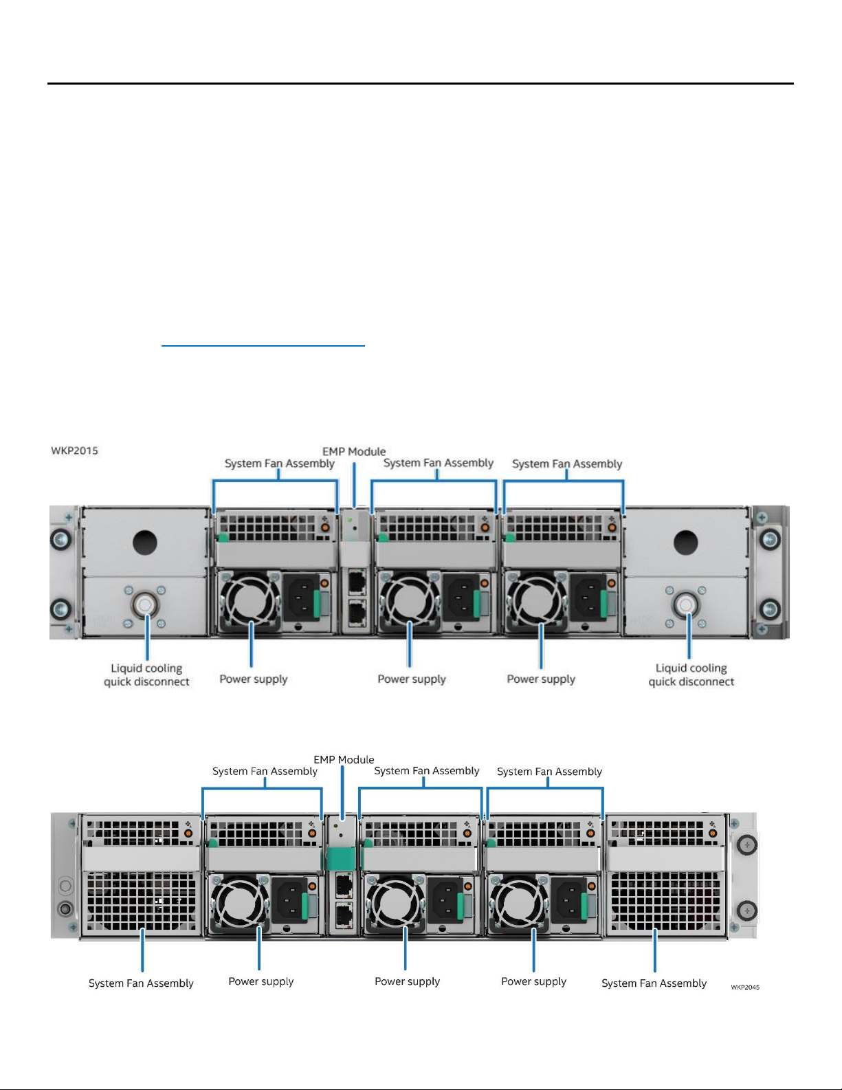
Figure 1. Liquid cooled system back view ................................................................................................................................ 15
Figure 2. Air cooled system back view ...................................................................................................................................... 15
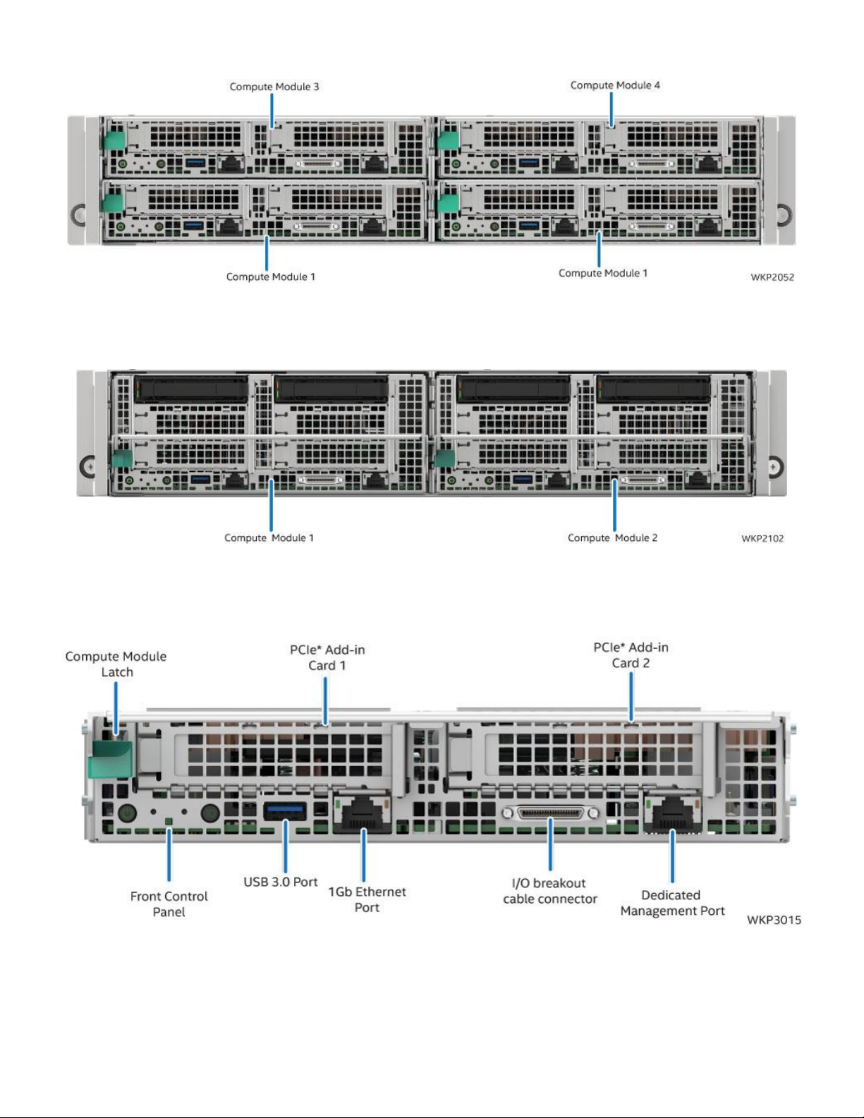
Figure 3. Compute module identification – 4 node system with 1U compute modules ........................................... 16
Figure 4. Compute module identification – 2 node systems with 2U compute modules ......................................... 16
Figure 5. 1U compute module front panel feature identification ..................................................................................... 16
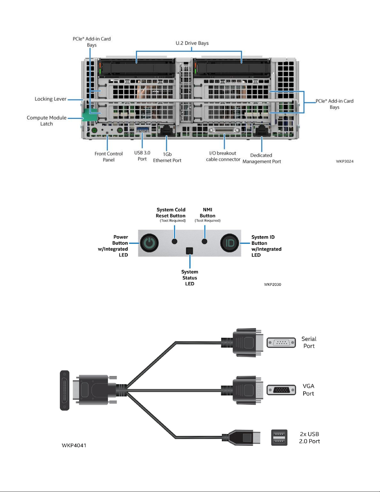
Figure 6. 2U compute module front panel feature identification ..................................................................................... 17
Figure 7. Front control panel features ....................................................................................................................................... 17
Figure 8. I/O breakout cable connector identification ......................................................................................................... 17
Figure 9. Securing the front of the rack rail ............................................................................................................................. 19
Figure 10. Securing the back of the rail ..................................................................................................................................... 20
Figure 11. Installing the chassis into the rack ......................................................................................................................... 20
Figure 12. Liquid cooling supply and return connections................................................................................................... 21
Figure 13. Installing the Intel® VROC Upgrade Key ............................................................................................................... 23
Figure 14. Removing the Intel® VROC Upgrade Key .............................................................................................................. 23
Figure 15. Installing the Intel® RMM4 Lite Key ........................................................................................................................ 24
Figure 16. Removing the Intel® RMM4 Lite Key ...................................................................................................................... 24
Figure 17. Installing an add-in card ............................................................................................................................................ 25
Figure 18. Removing an add-in card .......................................................................................................................................... 25
Figure 19. Removing the EMP Bay Filler Blank ....................................................................................................................... 26
Figure 20. Installing the EMP module/blank ........................................................................................................................... 26
Figure 21. Removing the EMP module/blank .......................................................................................................................... 27
Figure 22. Server chassis component identification ............................................................................................................. 29
Figure 23. 1U liquid cooled compute module component identification ...................................................................... 30
Figure 24. 2U liquid cooled compute module component identification ...................................................................... 31
Figure 25. 2U air cooled compute module component identification ............................................................................ 32
Figure 26. Removing a compute module .................................................................................................................................. 33
Figure 27. Installing a compute module ................................................................................................................................... 34
Figure 28. Removing a riser assembly ....................................................................................................................................... 35
Figure 29. Installing a riser assembly ......................................................................................................................................... 36
Figure 30. Drive carrier extraction from the chassis.............................................................................................................. 37
Figure 31. 2.5” drive carrier assembly – drive/drive blank removal ................................................................................ 37
Figure 32. 2.5” drive carrier assembly – drive installation into the carrier .................................................................... 38
Figure 33. 2.5” drive carrier assembly – alignment features .............................................................................................. 38
Figure 34. Drive carrier installation into the chassis ............................................................................................................. 39
Figure 35. Removing the M.2 heat sink ..................................................................................................................................... 40
Figure 36. Removing the M.2 SSD ............................................................................................................................................... 40
Figure 37. Installing the M.2 SSD................................................................................................................................................. 41
Figure 38. Removing the M.2 heat sink ..................................................................................................................................... 41
Figure 39. Removing the system battery .................................................................................................................................. 42
Figure 40. Installing the system battery .................................................................................................................................... 42
Page 11

Intel® Server System S9200WK Product Family Setup and Service Guide
11
Figure 41. Removing the cross head screws ............................................................................................................................ 43
Figure 42. Removing the T-20 screws ....................................................................................................................................... 43
Figure 43. Removing the liquid cooling loop ........................................................................................................................... 44
Figure 44. Securing the cross head screws .............................................................................................................................. 45
Figure 45. Securing the T-20 screws .......................................................................................................................................... 45
Figure 46. Removing the air duct................................................................................................................................................. 46
Figure 47. Installing the air duct .................................................................................................................................................. 46
Figure 48. Removing the processor heat sink ......................................................................................................................... 47
Figure 49. Installing the processor heat sink ........................................................................................................................... 48
Figure 50. Removing the DIMM in an air cooled system ...................................................................................................... 49
Figure 51. Installing the DIMM in an air cooled system ....................................................................................................... 49
Figure 52. Locating and retrieving the memory replacement tool .................................................................................. 50
Figure 53. Removing the DIMM retention clips....................................................................................................................... 51
Figure 54. Removing the DIMM in a liquid cooled system .................................................................................................. 51
Figure 55. Installing the DIMM in a liquid cooled system .................................................................................................... 52
Figure 56. Installing the DIMM retention clips ........................................................................................................................ 52
Figure 57. Removing a DIMM thermal pad ............................................................................................................................... 53
Figure 58. Installing a DIMM thermal pad ................................................................................................................................. 54
Figure 59. Removing the power supply ..................................................................................................................................... 54
Figure 60. Installing the power supply ...................................................................................................................................... 55
Figure 61. System Fan Configuration - Liquid cooled system ........................................................................................... 56
Figure 62. System Fan Configuration - Air cooled system ................................................................................................. 56
Figure 63. Removing the system fan .......................................................................................................................................... 57
Figure 64. Installing the system fan ............................................................................................................................................ 57
Figure 65. Removing the quick connect fillers ........................................................................................................................ 58
Figure 66. Removing the quick connect screws ..................................................................................................................... 59
Figure 67. Removing quick connect covers ............................................................................................................................. 59
Figure 68. Removing the back cover .......................................................................................................................................... 59
Figure 69. Removing the chassis plumbing assembly .......................................................................................................... 60
Figure 70. Installing the chassis plumbing assembly ........................................................................................................... 61
Figure 71. Installing quick connect covers ............................................................................................................................... 62
Figure 72. Securing the quick connect couplings to the covers ....................................................................................... 62
Figure 73. Installing the quick connect fillers ......................................................................................................................... 63
Figure 74. Securing the back cover............................................................................................................................................. 63
Figure 75. Removing the back cover .......................................................................................................................................... 64
Figure 76. Disconnecting the system fan power cables....................................................................................................... 65
Figure 77. Removing the power distribution board .............................................................................................................. 66
Figure 78. Installing the power distribution board ................................................................................................................ 67
Figure 79. Connecting system fan power cables.................................................................................................................... 68
Figure 80. Securing the back cover............................................................................................................................................. 69
Figure 81. Removing the internal chassis rail .......................................................................................................................... 70
Figure 82. Installing the internal chassis rail ........................................................................................................................... 71
Page 12

Intel® Server System S9200WK Product Family Setup and Service Guide
12
Figure 83. DIMM population for liquid cooled compute modules with 8 DIMMs of up to 32GB capacity .......... 78
Figure 84. DIMM population for liquid cooled compute modules with 8 DIMMs of 64GB capacity ..................... 79
Figure 85. DIMM population for air cooled compute modules with 8 DIMMs .............................................................. 79
Figure 86. DIMM population for liquid and air cooled compute modules with 16 DIMMs ...................................... 80
Figure 87. POST diagnostic LED identification ....................................................................................................................... 83
Page 13

Intel® Server System S9200WK Product Family Setup and Service Guide
13
List of Tables
Table 1. System status LED state definitions .......................................................................................................................... 81
Table 2. POST progress code LED example ............................................................................................................................ 83
Table 3. MRC progress codes ....................................................................................................................................................... 85
Table 4. MRC fatal error codes ..................................................................................................................................................... 86
Table 5. POST progress codes ..................................................................................................................................................... 87
Table 6. POST Error Codes and Messages ............................................................................................................................... 90
Table 7. Product family reference collaterals ...................................................................................................................... 110
Page 14

Intel® Server System S9200WK Product Family Setup and Service Guide
14
<This page is intentionally left blank>
Page 15
Intel® Server System S9200WK Product Family Setup and Service Guide
15
1. Introduction
1.1 The Intel® Server System S9200WK Product Family
The Intel® Server System S9200WK is a density-optimized, rack-mounted, 2U, multi-node product family
that is designed to support high-density, high-performance computing environments in both liquid and air
cooled configurations. Each system within the Intel Server System S9200WK product family includes
independent, pre-configured compute modules that allow for a power-on ready installation.
1.2 About This Document
This setup and service guide provides system integrators and service technicians guidance for the setup,
configuration, upgrade, and future maintenance of the Intel Server System S9200WK product family.
Refer to Appendix G for the complete list of documentation available. For the latest revision of this
document go to http://www.intel.com/support.
1.3 System Overview and Feature Identification
The illustrations on the following pages provide a quick reference identifying the key features of this server
product family.
Figure 1. Liquid cooled system back view
Figure 2. Air cooled system back view
Page 16
Intel® Server System S9200WK Product Family Setup and Service Guide
16
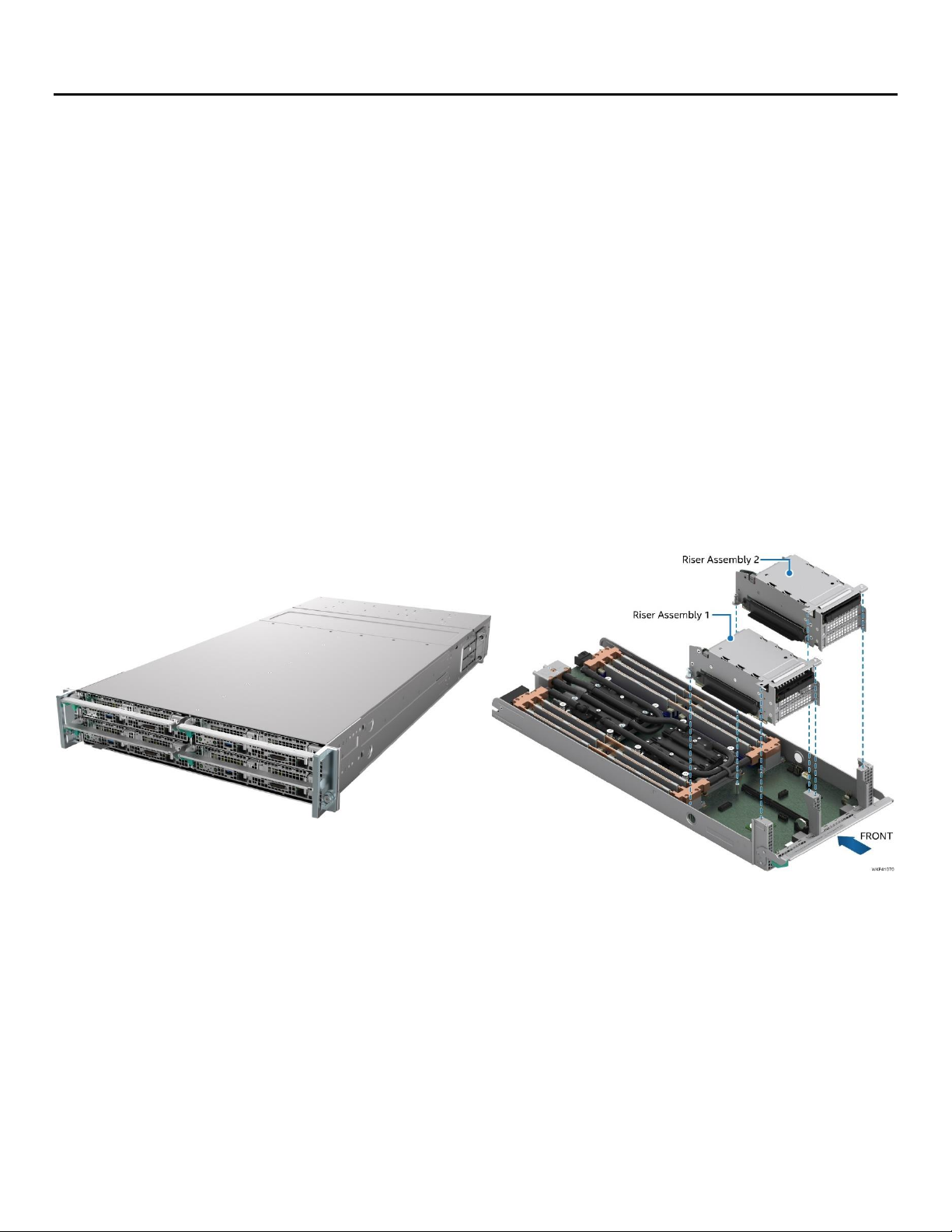
Figure 3. Compute module identification – 4 node system with 1U compute modules
Figure 4. Compute module identification – 2 node systems with 2U compute modules
Figure 5. 1U compute module front panel feature identification
Page 17
Intel® Server System S9200WK Product Family Setup and Service Guide
17
Figure 6. 2U compute module front panel feature identification
Figure 7. Front control panel features
Figure 8. I/O breakout cable connector identification
Page 18
Intel® Server System S9200WK Product Family Setup and Service Guide
18
2. System Setup
Each server system within the Intel® Server System S9200WK product family includes power supplies,
cooling components, rack mounting accessories, and configurable compute modules that include memory,
storage, and network components. Refer to the Intel® Server System S9200WK Product Family Configuration
Guide for a complete list of available options.
This chapter provides service personnel the information necessary to set up the Intel Server System
S9200WK product family. Illustrations identify the system features and procedures to install the system in a
rack environment and prepare it for use. The system comes fully assembled containing all components
necessary to be fully functional, so that once the system is physically set up in the operating environment
and updated to the latest available firmware version, it is ready for use.
Before Setting Up or Servicing the Intel® Server System S9200WK
Before working with this server product, observe the safety and ESD precautions found in the beginning of
this guide.
System Directional Reference
All references to left, right, front, top, and bottom assume the reader is facing the front of the chassis and
front of a compute module.
2.1 Requirements for liquid cooled systems
The liquid cooled systems within the Intel® Server System S9200WK product family are designed to operate
while being connected to a non-Intel coolant distribution unit that supports Staubli* SCG 06 quick connect
couplings.
Server Chassis
Compute Module
Page 19
Intel® Server System S9200WK Product Family Setup and Service Guide
19
2.2 Installing the System Into a Rack
Before following the instructions in this section, remove all compute modules from the server chassis (see
Section 4.2.1). If the rail kit is already installed, proceed to Section 2.2.2.
2.2.1 Installing the Fixed Rail Kit
The Intel® Server System S9200WK product family includes a fixed rail kit that serves as a shelf for the
system upon installation into the rack. When a system is installed onto the fixed rails, it can be secured to
both the rail and the rack through a pair of thumbscrews on the front of the system.
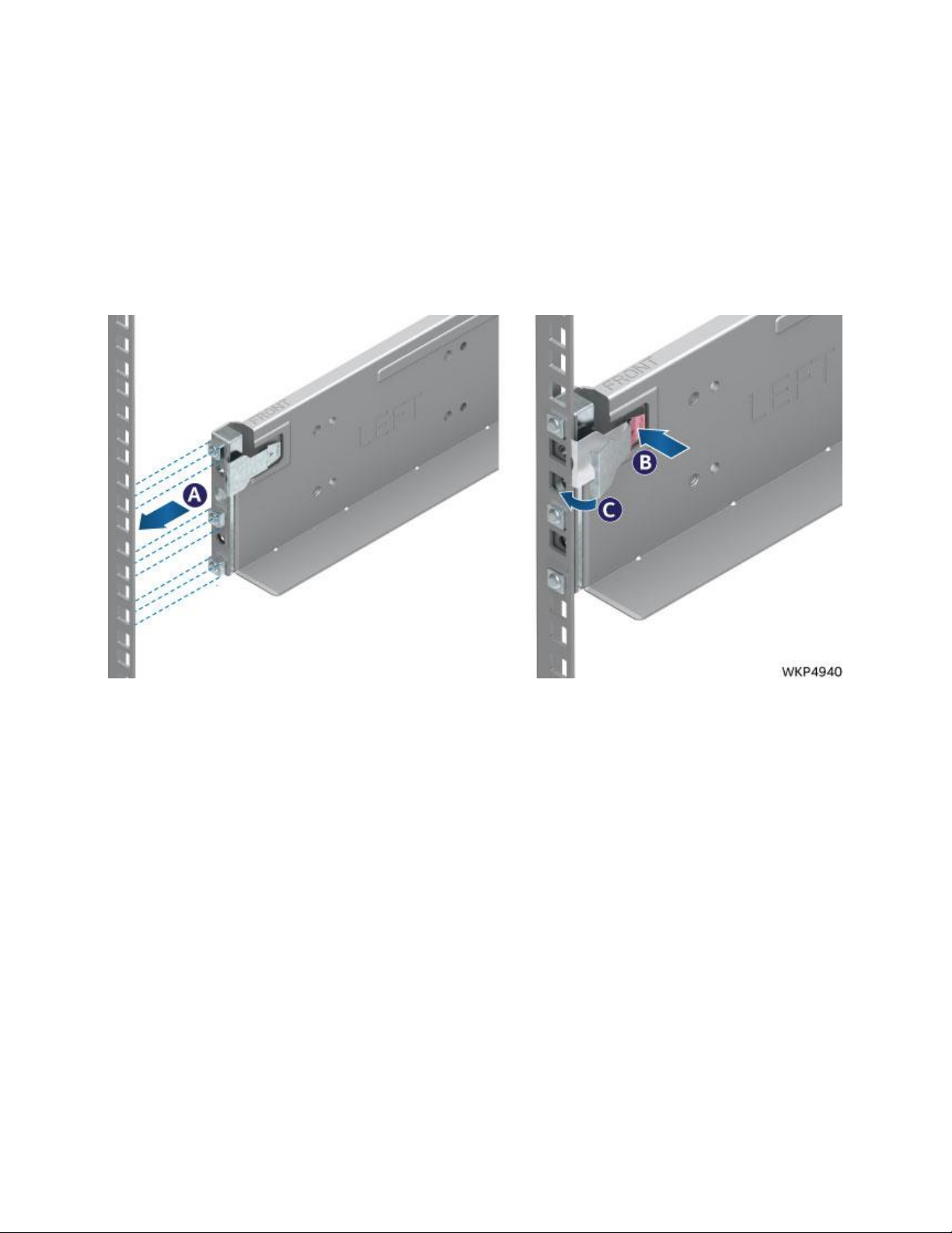
Figure 9. Securing the front of the rack rail
1. Remove the chassis rail kit from the packaging. Locate the rail, either left or right, and align the rail
guides with the slots in the front of the rack (see Letter A).
2. Insert the rail guides into their respective rack slots while pressing on the clip (see Letter B).
3. Release the clip once the guides are fully inserted into the rack (see Letter C).
Page 20
Intel® Server System S9200WK Product Family Setup and Service Guide
20
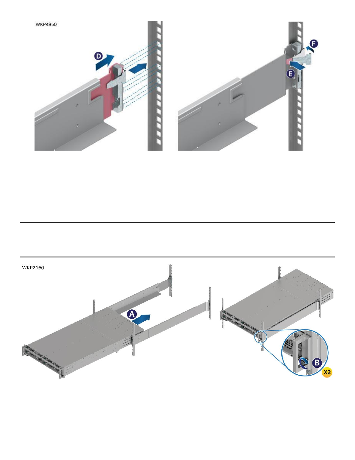
Figure 10. Securing the back of the rail
4. Extend and align the rear guides with their slots in the back of the rack (see Letter D).
5. Insert the rail guides into their respective rack slots while pressing on the clip (see Letter E).
6. Release the clip once the guides are fully inserted into the rack (see Letter F).
7. Repeat this process with the opposite rail.
2.2.2 Installing the Chassis Into a Rack
Important Safety Note: Due to the weight of a fully configured system, Intel® recommends using a
mechanical lift to aid with the installation of the system into the rack, and/or to use at least two people to
install the system into the rack, or remove all installed compute modules from the system before attempting
to install the system into the rack.
Figure 11. Installing the chassis into the rack
1. Insert the chassis onto the rails and slide it back to the rear of the rack (see Letter A).
2. Tighten the thumbscrews located on the chassis handles to secure the chassis to the rack (see Letter
B).
3. If removed, install the compute modules into the chassis (see Section 4.2).
Page 21
Intel® Server System S9200WK Product Family Setup and Service Guide
21
2.3 Connecting the System to a Liquid Coolant Supply
The liquid cooled systems within the Intel® Server System S9200WK product family include Staubli* SCG O6
quick connect couplings on the back of the chassis. When integrating a liquid cooled system into an
operating environment, it must be connected to the facility’s liquid coolant supply.
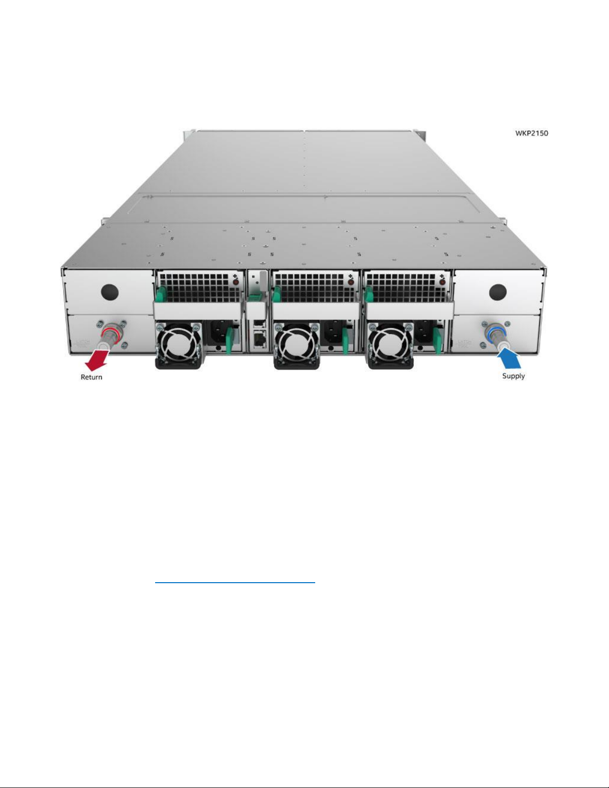
Figure 12. Liquid cooling supply and return connections
1. Locate the two quick connect couplings in the rear of the chassis as shown in Figure 12.
2. Attach the liquid supply to the quick connect coupling marked with a blue ring.
3. Attach the liquid return to the quick connect coupling marked with a red ring.
2.4 Updating System Firmware
Each compute module within the Intel® Server System S9200WK product family includes a software stack
that includes a BIOS, BMC firmware, Intel® Management Engine (Intel® ME) firmware, and both FRU and SDR
data. A full software stack is installed during the system manufacturing process, but may not be the latest
available version. Intel highly recommends updating the full system software stack on each installed
compute module to the latest available version for optimal performance and system reliability. A System
Update Package (SUP) containing the latest available system software stack can be downloaded from the
following Intel web site: http://downloadcenter.intel.com.
To ensure that the embedded platform management subsystem is configured properly, the latest FRU and
SDR data for each compute module must be installed after updating the full system software stack. Updated
FRU and SDR data allows the platform management subsystem to monitor the specific system sensors used
to determine appropriate system cooling, optimal performance, and accurate error reporting. FRU and SDR
data is loaded by using the FRUSDR utility which is included with the System Update Package (SUP).
Page 22
Intel® Server System S9200WK Product Family Setup and Service Guide
22
3. Optional Accessory Kit Integration and Service
This chapter provides installation and removal instructions for supported optional accessory kits.
Before Beginning
Before working with the server product, observe the safety and ESD precautions found in the Warnings
section at the beginning of this guide.
Ensure the compute module is powered off before removing it from the system chassis
Required Tools and Supplies
1. Anti-static wrist strap and conductive foam pad (recommended)
System Reference
All references to left, right, front, top, and bottom assume the reader is facing the front of the server chassis
or compute module.
Server Chassis
Compute Module
Page 23
Intel® Server System S9200WK Product Family Setup and Service Guide
23
3.1 Intel® Virtual RAID on CPU (Intel® VROC) Upgrade Key – IPC VROCSTANMOD
3.1.1 Installing the Intel® Virtual RAID on CPU (Intel® VROC) Upgrade Key
Figure 13. Installing the Intel® VROC Upgrade Key
1. Remove the compute module to be serviced from the server chassis and place it on to an anti-static
work surface (see Section 4.2.1)
2. Remove the right riser assembly from Riser Slot 2. (see Section 0)
3. Remove the Intel® VROC Upgrade Key from its packaging.
4. Locate the white 4-pin key connector near the right edge of the server board
5. Place the key over the connector and confirm that the orientation of the key matches that of the
connector.
6. Press the key down onto the connector.
3.1.2 Removing the Intel® Virtual RAID on CPU (Intel® VROC) Upgrade Key
Figure 14. Removing the Intel® VROC Upgrade Key
1. Remove the compute module to be serviced from the server chassis and place it on to an anti-static
work surface (see Section 4.2.1)
2. Remove the right riser assembly from Riser Slot 2. (see Section 0)
3. Using the key pull tab, carefully pull the key up until it disengages from the connector.
Page 24
Intel® Server System S9200WK Product Family Setup and Service Guide
24
3.2 Intel® Remote Management Module 4 Lite (Intel® RMM4 Lite) Key – iPC
AXXRMM4LITE2
3.2.1 Installing the Intel® Remote Management Module 4 Lite (Intel® RMM4 Lite) Key
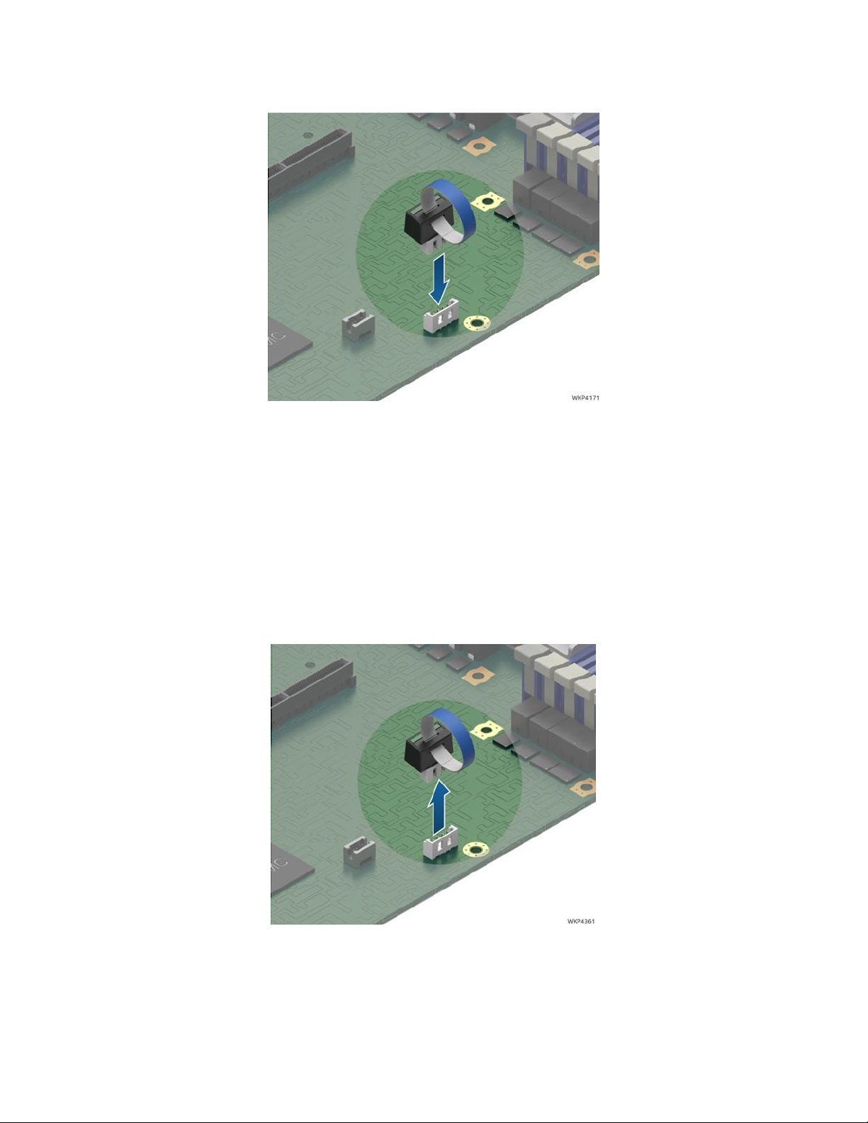
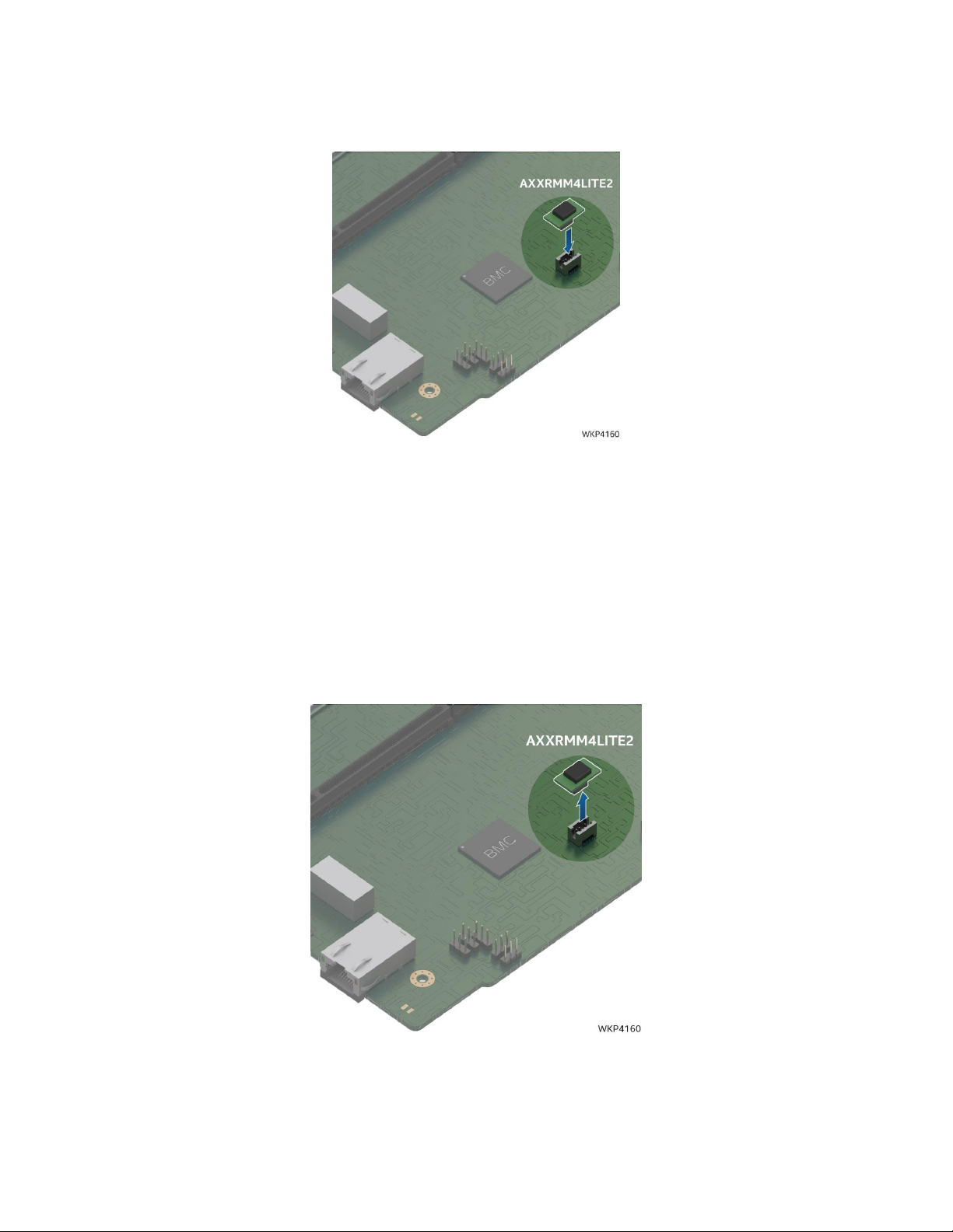
Figure 15. Installing the Intel® RMM4 Lite Key
1. Remove the compute module to be serviced from the server chassis and place it on to an anti-static
work surface (see Section 4.2.1)
2. Remove the right riser assembly from Riser Slot 2. (see Section 0)
3. Remove the Intel RMM4 Lite Key from its packaging.
4. Locate the Intel RMM4 Lite key connector near the right edge of the server board behind the RJ45
Management Port connector.
5. Match the orientation of the Intel RMM4 Lite key to the onboard connector.
6. Press the Intel RMM4 Lite key down into the connector until fully engaged.
3.2.2 Removing the Intel® Remote Management Module 4 Lite (Intel® RMM4 Lite) Key
Figure 16. Removing the Intel® RMM4 Lite Key
1. Remove the compute module to be serviced from the server chassis and place it on to an anti-static
work surface(see Section 4.2.1)
2. Remove the right riser assembly from Riser Slot 2. (see Section 0)
3. Carefully grasp the Intel® RMM4 Lite key and pull it up until disengaged from the connector.
Page 25
Intel® Server System S9200WK Product Family Setup and Service Guide
25
3.3 PCIe* Add-In Card
The following procedures are identical for both 1U and 2U riser card assemblies
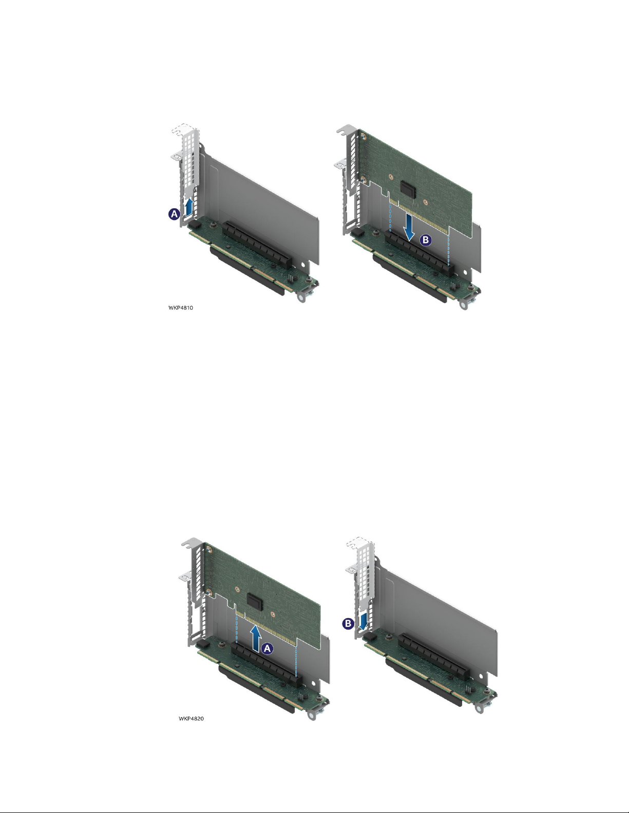
3.3.1 Installing a PCIe* Add-In Card
Figure 17. Installing an add-in card
1. Remove the compute module to be serviced from the server chassis and place it on to an anti-static
work surface (see Section 4.2.1)
2. Remove the selected riser assembly from the compute module (see Section 0)
3. If present, carefully remove the rear metal filler plate from the metal frame of the riser assembly (see
Letter A).
4. Align the rear bracket of the add-in card to the rear opening of the riser assembly
5. Carefully push the add-in card down into the PCIe slot (see Letter B).
6. Ensure the add-in card is fully seated
7. Re-install the riser card assembly into the compute module (see Section 4.3)
3.3.2 Removing a PCIe* Add-In Card
Figure 18. Removing an add-in card
1U riser card assembly shown**
1U Riser assembly shown **
Page 26
Intel® Server System S9200WK Product Family Setup and Service Guide
26
1. Remove the compute module to be serviced from the server chassis and place it on to an anti-static
work surface (see Section 4.2.1)
2. Remove the selected riser assembly from the compute module (see Section 0)
3. Carefully remove the add-in card from the PCIe slot (see Letter A).
4. Carefully install the metal filler plate over the opening on the metal frame of the riser assembly (see
Letter B).
5. Re-install the riser card assembly into the compute module (see Section 4.3)
3.4 Ethernet Management Port Module (EMP Module) – iPC AXXFCEMP
Your system may or may not come preconfigured with an Ethernet Management Port Module. This section
provides instruction for the installation and removal of this accessory option. The EMP module is hot-swap
capable. It can be installed or removed without powering down the system or any of its compute modules.
3.4.1 Installing the EMP Module
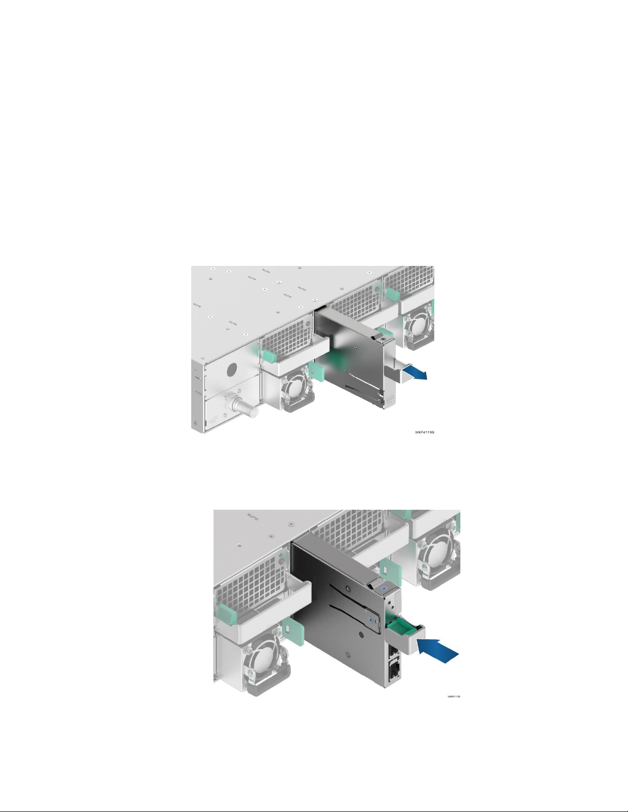
Figure 19. Removing the EMP Bay Filler Blank
1. If present, remove the EMP Bay Filler blank from the back of the server chassis by pulling it out from
the chassis as shown in Figure 19.
Figure 20. Installing the EMP module/blank
2. Install the EMP module, by sliding it into the open EMP bay until it locks into place (see Letter A).
A
Page 27
Intel® Server System S9200WK Product Family Setup and Service Guide
27
3.4.2 Removing the EMP Module
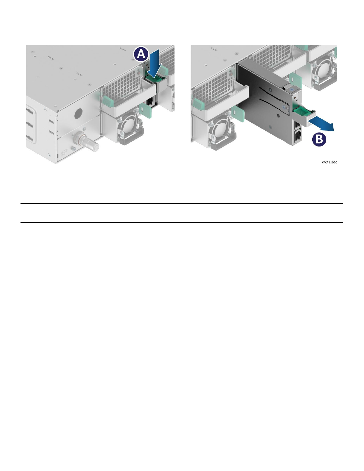
1. Locate the EMP module on the back of the chassis.
Figure 21. Removing the EMP module/blank
2. Remove the EMP module by pushing down on the Green latch (see Letter A) and then pulling it out
from the chassis (see Letter B).
Note: To keep the system operating within its thermal limits, the EMP module bay must be populated with
either an EMP module or EMP blank when any of the installed compute modules are operational.
Page 28
Intel® Server System S9200WK Product Family Setup and Service Guide
28
4. System Service
This chapter provides instructions for removing and installing system components considered field
replaceable (field-replaceable units, or FRUs). The Intel® Server System S9200WK product family features a
modular design, allowing for servicing of system fans, power supply modules, compute modules and
Ethernet Management Port module (EMP module) without having to power off the entire system.
System components that do require that the full system be powered off and AC power cords disconnected
from the system include the following:
For air cooled configurations:
• Power distribution board
For liquid cooled configurations:
• Power distribution board
• Chassis plumbing assembly
When service is necessary for any of the individual compute modules within the server system, it is
necessary to power off the selected compute module before removing it from the server chassis.
Before Setting Up or Servicing the Intel® Server System S9200WK
Before working with this server product, observe the safety and ESD precautions found at the beginning of
this guide.
System Directional Reference
All references to left, right, front, top, and bottom assume the reader is facing the front of the server chassis
or the front of the compute module.
Server Chassis
Compute Module
Page 29
Intel® Server System S9200WK Product Family Setup and Service Guide
29
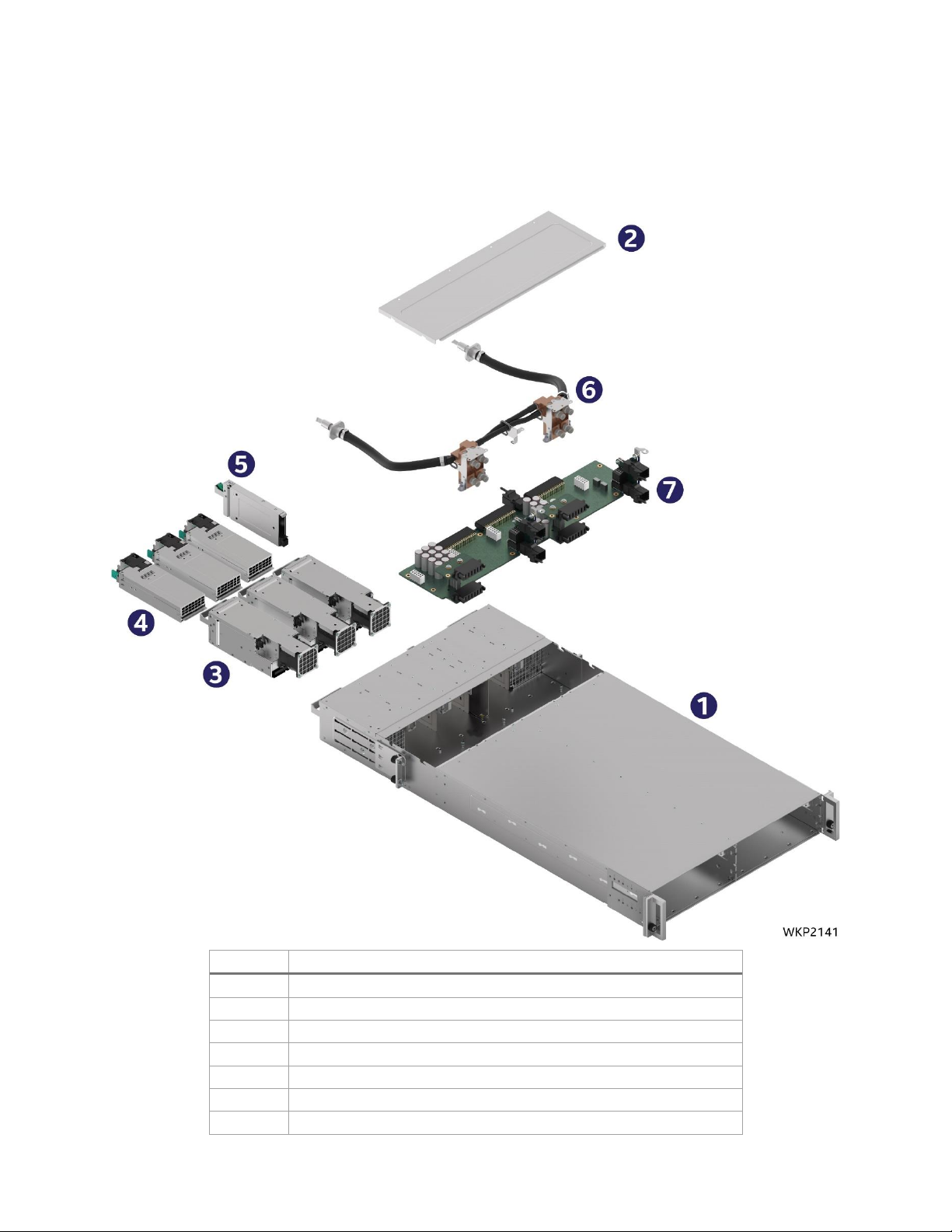
4.1 System Component Identification
The following illustrations provide a quick reference to identify system components that are considered field
serviceable. Refer to the Intel® Server System S9200WK product family Configuration Guide for a complete
list of available spares.
Number
Name
1
Server Chassis
2
Chassis back cover
3
System fan assemblies
4
Power supplies
5
EMP module
6
Chassis plumbing assembly (Liquid cooled systems only)
7
Power distribution board
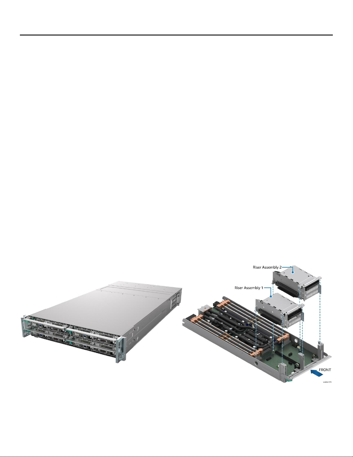
Figure 22. Server chassis component identification
Page 30
Intel® Server System S9200WK Product Family Setup and Service Guide
30
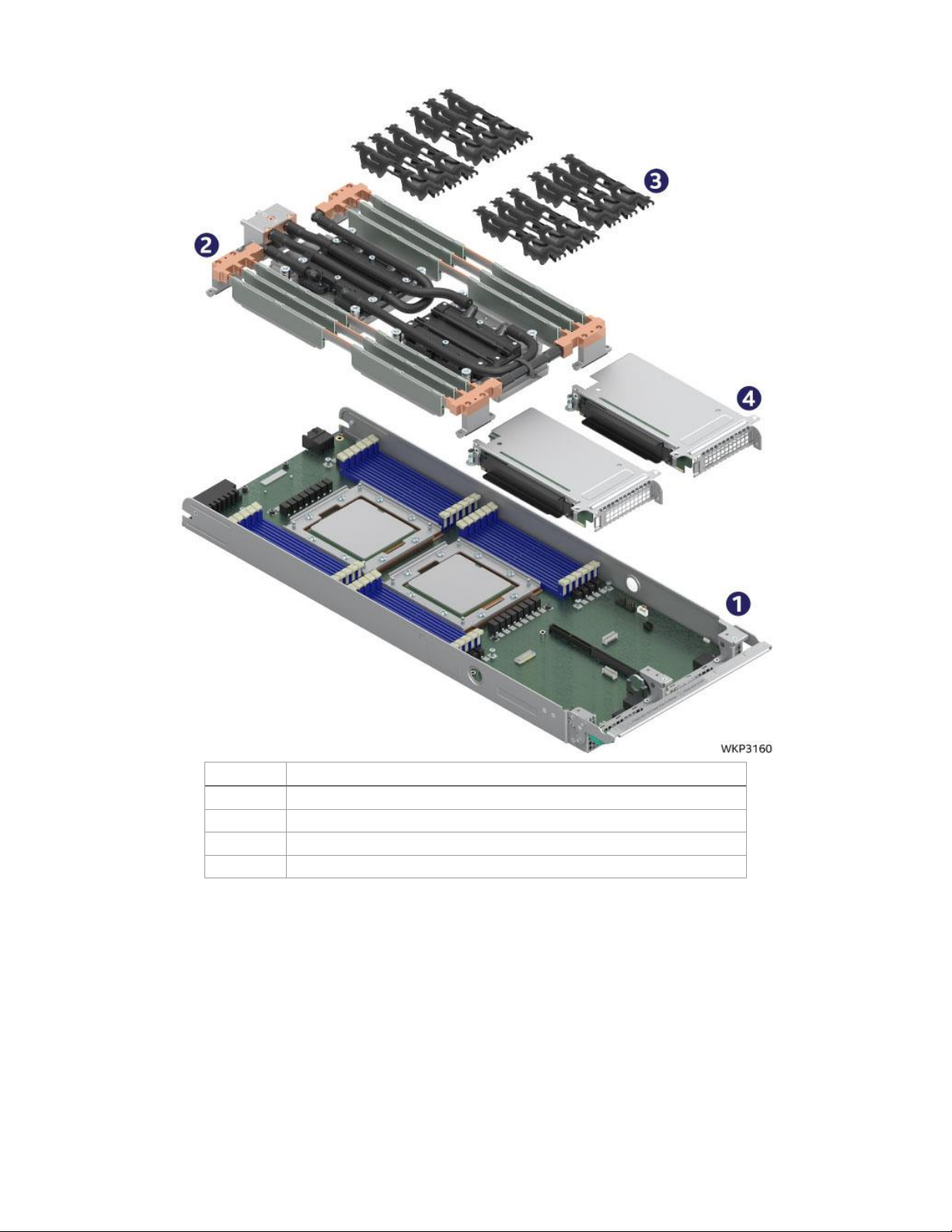
Number
Name
1
Compute module tray with server board
2
Liquid cooling loop
3
DIMM retention clips
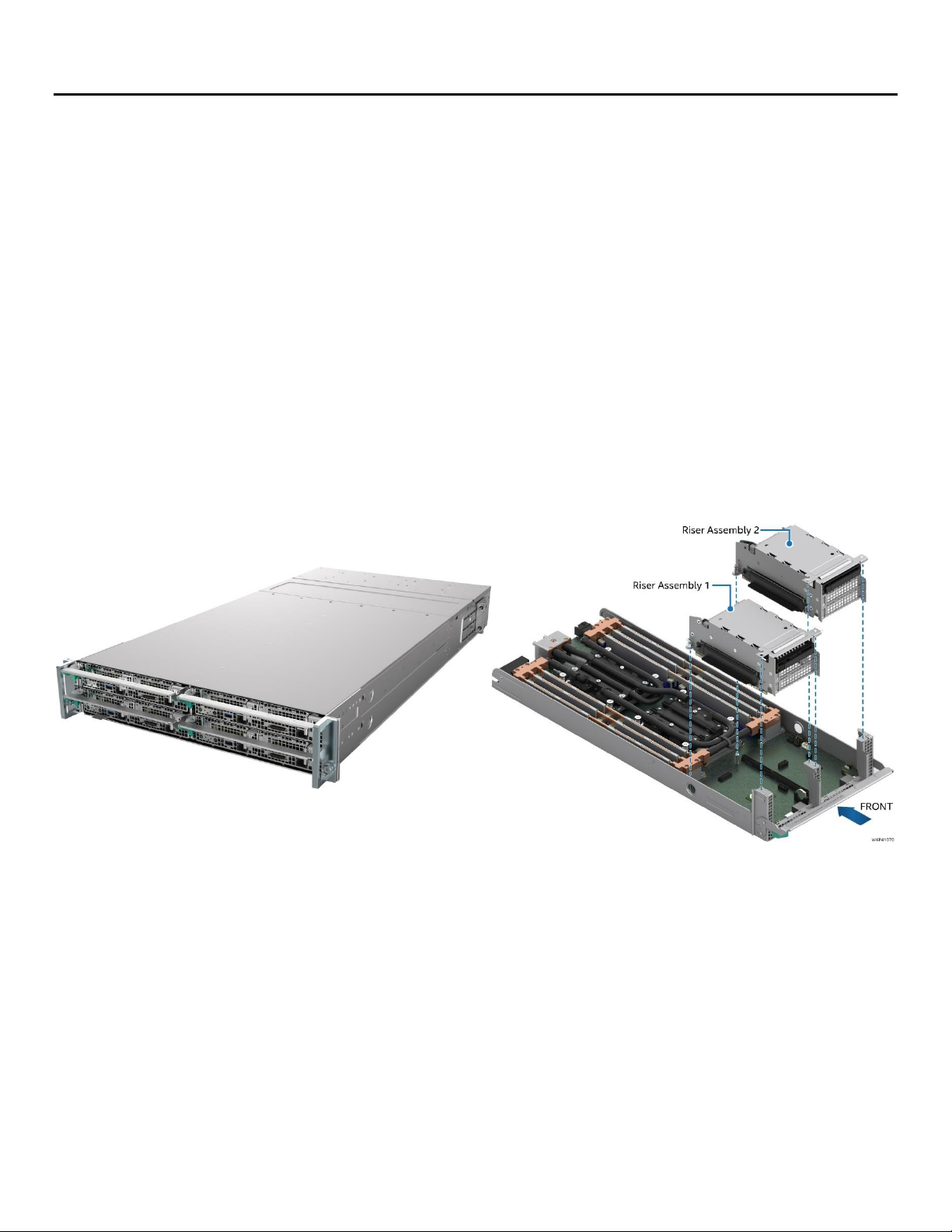
4
Riser assemblies
Figure 23. 1U liquid cooled compute module component identification
Page 31

Intel® Server System S9200WK Product Family Setup and Service Guide
31
Number
Name
1
Compute module tray with server board
2
Liquid cooling loop
3
DIMM retention clips
4
Riser assemblies
Figure 24. 2U liquid cooled compute module component identification
Page 32

Intel® Server System S9200WK Product Family Setup and Service Guide
32
Number
Name
1
Compute module tray with server board
2
CPU Heat sinks
3
Air duct
4
Riser assemblies
Figure 25. 2U air cooled compute module component identification
Page 33

Intel® Server System S9200WK Product Family Setup and Service Guide
33
4.2 Compute Module Replacement
All installed compute modules within an Intel® Server System S9200WK are independent from each other.
Servicing a compute module does not require having to power down the full server system. Only the
compute module to be serviced must be powered down before being removed from the server chassis.
Replacement of compute modules (spare or warranty replacement) will include the following:
• Compute Module Tray
• Server Board with processors
• Riser Card Assemblies
• Liquid Cooling Loop (liquid cooled compute modules only)
• Processor Heat Sinks (air cooled compute modules only)
• Air Duct (2U air cooled compute modules only)
When returning a compute module for warranty replacement, the following components must be removed
before shipment (if present) :
• Memory (DIMMs)
• DIMM retention clips
• PCIe* add-in cards
• Add-on storage devices (M.2 SSD, U.2 SSD)
• Intel® RMM4 Lite key
• Intel® VROC upgrade key
Note: Processors are soldered to the server board, they are not removable. Processors are included when
ordering a spare or warranty replacement compute module. Refer to the Intel® Server System S9200WK
Product Family Configuration Guide for available spares.
The following procedures are identical for both 1U and 2U compute modules.
4.2.1 Compute Module Removal
1. Power down the compute module using the Power Button located on the front panel of the
compute module to be serviced.
Figure 26. Removing a compute module
Page 34

Intel® Server System S9200WK Product Family Setup and Service Guide
34
2. Press the green latch inward (see Letter A) and lower the lever in front of the compute module (see
Letter B).
3. Grasp the lever and pull out the compute module from the chassis (see Letter C).
Note: To keep the system operating within its thermal limits, compute module bays must be populated
with either a compute module or blank when any of the installed compute modules are operational.
4.2.2 Compute Module Installation
Replacement compute modules can be re-installed into a server chassis without impacting the operation or
functionality of other operational compute modules.
•
Figure 27. Installing a compute module
1. Ensure the lever in front of the compute module is lowered. If not, press the green latch inward and
lower the lever.
2. Align the compute module to its corresponding bay and push it into the chassis until the key pins in
the lever are inside the chassis inner wall key hole.
3. Raise the lever to secure the compute module. (see Letter B)
2U Compute Module shown **
Page 35

Intel® Server System S9200WK Product Family Setup and Service Guide
35
4.3 Riser Assembly Replacement
Before following the instructions in this section, remove the Intel® compute module (see Section 4.2.1)
needing service. This procedure applies to both 1U and 2U compute modules.
Required Tools and Supplies:
• Anti-static wrist strap and conductive foam pad (recommended)
• Phillips head screwdriver
4.3.1 Riser Assembly Removal
Figure 28. Removing a riser assembly
1. Remove the three screws that secure the riser assembly to the compute module (see Letter A).
2. Carefully remove the riser assembly by lifting it up away from the compute module (see Letter B).
If the riser assembly is going to be shipped as part of a warranty replacement, remove all installed add-in
cards and/or storage SSDs.
Page 36

Intel® Server System S9200WK Product Family Setup and Service Guide
36
4.3.2 Riser Assembly Installation
Figure 29. Installing a riser assembly
1. Align the riser card edge connector to the riser slot on the server board (see Letter A).
2. Carefully push down on the riser assembly until the riser card is securely seated into the riser slot.
3. Ensure the three screw holes of the riser assembly are aligned and flush with the mounting holes of
the compute module.
4. With three screws, secure the riser assembly to the compute module using 8 lbs. of torque on each
(see Letter B).
4.4 Drive Carrier Extraction, Assembly, and Installation
The 2U compute modules of the Intel® Server System S9200WK product family have support for up to two
hot-swap 2.5” form factor U.2 Solid State Drives (SSDs). Each drive installed to a tool-less drive carrier. This
section provides instructions for drive extraction from the chassis, drive assembly, and drive installation into
the chassis.
Required Tools and Supplies:
• Anti-static wrist strap and conductive foam pad (recommended)
Page 37

Intel® Server System S9200WK Product Family Setup and Service Guide
37
4.4.1 Drive Carrier Extraction
Figure 30. Drive carrier extraction from the chassis
1. Press the button on the carrier face plate to release the lever (see Letter A).
2. Using the lever, pull the carrier from the drive bay (see Letter B).
4.4.2 Drive Carrier Assembly
Important: The S9200WK server product family is designed and tested to support 2.5” U.2 NVMe* Solid
State Drives only.
Figure 31. 2.5” drive carrier assembly – drive/blank removal
1. Remove the drive (or drive blank) from the carrier by gently rotating the top edge of a carrier rail
outwards while simultaneously pushing the drive up from the bottom as shown in .
Page 38

Intel® Server System S9200WK Product Family Setup and Service Guide
38
Figure 32. 2.5” drive carrier assembly – drive installation into the carrier
2. Carefully unpack the new drive, taking care not to touch any of the connector pins located on the
back side of the drive.
3. With the rear drive connector positioned toward the back of the drive carrier, align and position the
mounting holes on one side of the drive over the mounting tabs located on the drive carrier side rail
(see Letter A).
4. Lower the other side of the drive into the carrier (see Letter B) and press down on the drive until all
mounting tabs are locked in place.
Figure 33. 2.5” drive carrier assembly – alignment features
Note: The 2.5” drive blank and drive carrier each have alignment features (shown in ) ensuring proper
assembly. When re-installing a drive blank into the drive carrier ensure the features are aligned prior to
installation, as failure to properly install a drive blank may result in the carrier assembly not fitting properly
into the drive bay.
Page 39

Intel® Server System S9200WK Product Family Setup and Service Guide
39
4.4.3 Drive Carrier Installation
Figure 34. Drive carrier installation into the chassis
1. Align the drive assembly with the open drive bay.
2. With the lever in the open position, insert the drive assembly into the drive bay (see Letter A) and
push forward until the drive makes contact with the internal backplane.
3. Complete the drive installation by closing the drive assembly lever until it locks into place (see Letter
B).
4.5 M.2 SSD Replacement
Before following the instructions in this section, remove the selected compute module (see Section 4.2.1)
from the server chassis and then remove the selected riser assembly from the compute module (see Section
0).
This procedure applies to both 1U and 2U riser assemblies with illustrations showing differences where
applicable.
Required Tools and Supplies:
• Anti-static wrist strap and conductive foam pad (recommended)
• Phillips head screwdriver
Page 40

Intel® Server System S9200WK Product Family Setup and Service Guide
40
4.5.1 M.2 Heat Sink Removal
The riser assembly includes an M.2 heat sink that must be removed prior to servicing any M.2 SSD.
Figure 35. Removing the M.2 heat sink
1. Locate the heat sink on the left side of the riser assembly and remove the screw (see Letter A).
2. Slide the heat sink in the direction shown to remove it (see Letter B).
4.5.2 M.2 SSD Removal
Figure 36. Removing the M.2 SSD
1. Remove the screw from the M.2 mounting stand-off on the left side of the riser assembly (see Letter
A).
2. Carefully rotate outward the free end of the M.2 SSD away from the riser assembly (see Letter B).
3. Grasp the M.2 SSD by its edges and gently remove it from the connector in the direction shown (see
Letter C).
If no SSD is being installed:
4. Return the previously removed screw to the M.2 mounting stand-off.
5. Re-Install the M.2 heat sink on to the riser assembly (see Section 4.5.4).
1U Riser Assembly
2U Riser Assembly
1U Riser Assembly
2U Riser Assembly
Page 41

Intel® Server System S9200WK Product Family Setup and Service Guide
41
4.5.3 M.2 SSD Installation
Figure 37. Installing the M.2 SSD
1. If present, remove the screw from the M.2 mounting stand-off on the left side of the riser assembly.
2. Align the notch within the SSD edge connector with the key in the M.2 connector and insert the SSD
into the connector (see Letter A).
3. Push the free edge of the SSD towards the riser assembly (see Letter B) and secure the SSD to the M.2
mounting stand-off with the previously removed screw (see Letter C).
4. Install the M.2 Heat Sink (see Section 4.5.4)
4.5.4 M.2 Heat Sink Installation
Figure 38. Removing the M.2 heat sink
1. If installing a new heatsink, peel off the protective film from the thermal interface material.
2. Align the heat sink to the riser assembly and slide into place in the direction shown (see Letter A).
3. Ensure the screw holes are properly aligned then secure the heat sink to the riser assembly with a
screw (see Letter B).
1U Riser Assembly
2U Riser Assembly
1U Riser Assembly
2U Riser Assembly
Page 42

Intel® Server System S9200WK Product Family Setup and Service Guide
42
4.6 System Battery Replacement
Required Tools and Supplies:
• Anti-static wrist strap and conductive foam pad (recommended)
Before following the instructions in this section, remove the select compute module from the server chassis
(see Section 4.2.1), and then remove the riser assemblies from the compute module (see Section 4.3.1).
Figure 39. Removing the system battery
1. Locate the battery on the server board. See Figure 39.
2. Gently pull the metal clip to release the battery (see Letter A).
3. Remove the old battery from the plastic socket (see Letter B).
4. Dispose of the battery according to local laws.
5. Remove the new lithium battery from its package.
6. Orient the battery so the positive pole is facing towards the left side of the compute module.
Figure 40. Installing the system battery
7. Insert the battery into the battery socket. See Figure 40.
8. Use the <F2> BIOS Setup Utility to restore BIOS Settings and reset the system time and date.
Page 43

Intel® Server System S9200WK Product Family Setup and Service Guide
43
4.7 Liquid Cooling Loop Replacement (Liquid Cooled Compute Modules Only)
Before following the instructions in this section, remove the selected compute module from the server
chassis (see Section 4.2.1).
Required Tools and Supplies:
• Anti-static wrist strap and conductive foam pad (recommended)
• Phillips head screwdriver
• Torx* T-20 screwdriver
4.7.1 Liquid Cooling Loop Removal
Figure 41. Removing the cross head screws
1. Remove the ten screws indicated in Figure 41 with a phillips head screwdriver.
Figure 42. Removing the T-20 screws
2. Remove the eight screws indicated in Figure 42 with a Torx* T-20 screwdriver.
Page 44

Intel® Server System S9200WK Product Family Setup and Service Guide
44
Figure 43. Removing the liquid cooling loop
3. Carefully lift the liquid cooling loop assembly up and away from the compute module. See Figure 43.
Page 45

Intel® Server System S9200WK Product Family Setup and Service Guide
45
4.7.2 Liquid Cooling Loop Installation
1. Carefully unpack the new liquid cooling loop.
2. Carefully place the liquid cooling loop assembly into the compute module, ensuring that both the
DIMM cooling assembly and processor cold plates are properly aligned with the mounting screw
holes.
Figure 44. Securing the cross head screws
3. Place and secure the ten phillips head screws indicated in Figure 44 with a phillips head screwdriver
using 8 lbs. of torque.
Figure 45. Securing the T-20 screws
4. Using a cross pattern for each cooling plate, place and secure the eight Torx* head screws as
indicated in Figure 45 with a Torx* T-20 screwdriver using 8 lbs. of torque
2 3 4
3
2 4 1
Page 46

Intel® Server System S9200WK Product Family Setup and Service Guide
46
4.8 Air Duct Replacement (Air Cooled Compute Modules Only)
4.8.1 Air Duct Removal
Figure 46. Removing the air duct
1. Remove the compute module to be serviced from the server chassis (see Section 4.2.1).
2. Press the latches located on both sides of the compute module inwards (see Letter A).
3. Carefully lift the front edge of the air duct away from the compute module (see Letter B).
4. Pull the air duct away from the compute module (see Letter C).
4.8.2 Air Duct Installation
Figure 47. Installing the air duct
1. Align and attach the hinge slots located on the back end of the air duct with the hinge posts located
on both sides of the compute module (see Letter A).
2. Lower the air duct down until both the left and right side latches snap into place (see Letter B).
Page 47

Intel® Server System S9200WK Product Family Setup and Service Guide
47
4.9 Processor Heat Sink Replacement (Air Cooled Compute Modules Only)
Due to possible damage to the server board while attempting to remove/install the processor heat sink, Intel
does NOT recommend removing the processor heat sink outside of the following:
• The processor heat sink is damaged and needs to be replaced
• The processor heat sink is faulty and needs to be replaced
Before following the instructions in this section, remove the compute module to be serviced from the server
chassis (see Section 4.2.1) and remove the air duct (see Section 4.8.1).
Required Tools and Supplies:
• Anti-static wrist strap and conductive foam pad (recommended)
• Torx* T-20 screwdriver
4.9.1 Processor Heat Sink Removal
Figure 48. Removing the processor heat sink
Note: Extreme care should be taken when removing the heat sink from a fixed mounted processor.
• Care should be taken not to accidentally bend or knock off any components mounted on the server
board while attempting to remove the heat sink or clean the top side of the processor.
1. Using a Torx* T-20 screwdriver, loosen all captive (non-removable) processor heat sink screws until
each is free from the server board (see Letter A). No specific order is required.
2. It will be necessary to break the thermal interface bond that has formed between the processor and
the heat sink. To break the bond and remove the heat sink, carefully rotate the heat sink in a short
back and forth pattern while at the same time carefully lifting the heat sink away from the processor
(see Letter B).
3. Using a commercially available isopropyl alcohol cleaning pad or other similar cleaning tool, carefully
clean away all Thermal Interface Material (TIM) residue from both the bottom of the heatsink and the
top of the processor.
Page 48

Intel® Server System S9200WK Product Family Setup and Service Guide
48
• No excess cleaning agent should flow from the top side of the processor onto any part of the server
board
4.9.2 Processor Heat Sink Installation
Figure 49. Installing the processor heat sink
Note: Replacement processor heat sinks will include thermal interface material (TIM) on the bottom side of
the heat sink. If present, remove the protective film from the TIM before installing the heat sink onto the
processor.
1. Align and place the heat sink on top of the processor. No specific heat sink fin orientation is required.
2. Secure the screws indicated in Figure 49 with a Torx* T-20 screwdriver using 8 lbs. of torque, in an X
pattern, alternating between screws until all are tight.
Page 49

Intel® Server System S9200WK Product Family Setup and Service Guide
49
4.10 Memory (DIMM) Replacement
This section documents the procedure to follow when replacement of a faulty DIMM is necessary. The DIMM
replacement procedure for a liquid cooled compute module and an air cooled cooled compute module is
different. Refer to the appropriate sub-section for your specific compute module configuration.
For memory population rules, refer to Appendix B.
4.10.1 Air Cooled Compute Module DIMM Replacement
1. Remove the select compute module from the server chassis (see Section 4.2.1)
2. Remove the air duct from the computer module (see Section 4.8.1).
4.10.1.1 DIMM Removal
Figure 50. Removing the DIMM in an air cooled system
3. Identify and locate the faulty DIMM. Ensure that the ejection tabs of adjacent DIMM slots are closed.
4. Open the DIMM ejection tabs at both ends of the selected DIMM slot (see Letter A). The DIMM will
slightly lift up from the slot.
5. Holding the DIMM by its edges, lift it away from the slot (see Letter B).
4.10.1.2 DIMM Installation
Figure 51. Installing the DIMM in an air cooled system
1. Locate the DIMM slot for installation. Ensure that the DIMM ejection tabs at both ends of the DIMM
slot are pushed outward to the open position (see Letter A).
2. Carefully unpack the replacement DIMM, taking care to only handle the device by its outer edges.
3. Align the notch at the bottom edge of the DIMM with the key in the DIMM slot (see Letter B).
Page 50

Intel® Server System S9200WK Product Family Setup and Service Guide
50
4. Insert the DIMM into the slot (see Letter C) pushing down on the DIMM, until the ejection tabs snap
into place (see Letter D). Ensure that the ejection tabs are firmly in place (see Letter E).
4.10.2 Liquid Cooled Compute Module DIMM Replacement
The DIMM replacement procedure for a liquid cooled compute module requires removal, replacement, and
re-installation of several components. The documented procedure should be followed in the order specified
with little or no deviation.
1. Remove the select compute module from the server chassis (see Section 4.2.1)
2. Remove the air duct from the computer module (see Section 4.8.1).
4.10.2.1 DIMM Removal
The liquid cooled compute modules within the Intel® Server System S9200WK product family include a
memory replacement tool located on top of the cold plates of the liquid cooling loop. This tool can be used
to remove the DIMM retainer clips in memory configurations that require them, and to open the DIMM
ejection tabs.
Figure 52. Locating and retrieving the memory replacement tool
1. Locate the memory replacement tool on top of the CPU0 cold plate.
2. Remove the tool from one of its sides first (see Letter A) and then lift it away (see Letter B).
Page 51

Intel® Server System S9200WK Product Family Setup and Service Guide
51
If the compute module does not have DIMM retention clips installed, skip to step 6.
Figure 53. Removing the DIMM retention clips
3. Identify and locate the faulty DIMM
4. Use the memory removal tool as a lever and position one end between the DIMM retention clip and
the liquid cooling loop (see Letter A).
5. Lift the DIMM retention clip from the liquid cooling loop (see Letter B).
Figure 54. Removing the DIMM in a liquid cooled system
6. Using the memory replacement tool, open the DIMM ejection tabs at both ends of the DIMM slot (see
Letter A and Letter B). The DIMM will slightly lift up from the slot.
7. Hold the DIMM by its edges and lift it away from the slot (see Letter C).
Page 52

Intel® Server System S9200WK Product Family Setup and Service Guide
52
4.10.2.2 DIMM Installation
Figure 55. Installing the DIMM in a liquid cooled system
1. Locate the DIMM slot for installation. Ensuring that the DIMM ejection tabs at both ends of the DIMM
slot are pushed outward to the open position (see Letter A). Use the provided tool if the DIMM
ejection tabs are in the closed position (see Section 4.10.2.1).
2. Carefully unpack the replacement DIMM, taking care to only handle the device by its outer edges.
3. Align the notch at the bottom edge of the DIMM with the key in the DIMM slot (see Letter B).
4. Insert the DIMM into the slot (see Letter C) pushing down on the DIMM, until the ejection tabs snap
into place (see Letter D). Ensure that the ejection tabs are firmly in place (see Letter E).
Figure 56. Installing the DIMM retention clips
5. If the replacement DIMM is 64GB in capacity, re-install the DIMM retention clip over the select DIMM
pair and heat spreader as shown in Figure 56. Ensure the clip is securely in place.
Page 53

Intel® Server System S9200WK Product Family Setup and Service Guide
53
Memory Heat Spreader Thermal Pad Replacement (Liquid Cooled Compute
Modules only)
In liquid cooled compute module configurations, the heat generated from installed DIMMs is drawn out of
the compute module by means of an array of memory heat spreaders that are interconnected to the internal
plumbing of the liquid cooling loop. Each heat spreader is positioned in between two DIMMs. Thermal pads
are affixed to both sides of a heat spreader to ensure efficient heat dissipation from the DIMMs to the heat
spreader.
Should a thermal pad become damaged while installing or removing a DIMM, or become damaged or worn
for other reasons, the following sections provide the instructions necessary to remove and replace a heat
spreader thermal pad.
Note: To maintain optimal performance of the liquid cooling loop, Intel recommends replacing ALL thermal
pads at once.
4.11.1 Thermal Pad Removal
1. Remove the select compute module from the server chassis (see Section 4.2.1).
2. Remove all DIMMs from the compute module (see Section 4.10.2.1).
Figure 57. Removing a thermal pad
3. Carefully peel away the thermal pads from both sides of all heat spreaders.
4. Using isopropyl alcohol and a lint free cloth, carefully clean the surface of each heat spreader,
ensuring that no thermal pad residue remains.
Page 54

Intel® Server System S9200WK Product Family Setup and Service Guide
54
4.11.2 Thermal Pad Installation
Figure 58. Installing a thermal pad
1. Apply a new thermal pad to the heat spreader by aligning the thermal pad’s cutout edges with the
heat spreader’s shape (see Letter A).
2. Fold the thermal pad to the opposite side of the heat spreader (see Letter B).
3. Use a plastic tweezer (or the included DIMM removal tool) to apply pressure along the thermal pad
from one side to the other, ensuring that no air bubbles remain between the thermal pad and the
heat spreader.
4. Install the previously removed DIMMs (see Section 1.1).
4.12 Power Supply Replacement
Power supply modules are hot swappable when the system is configured in a redundant (2+1) power supply
configuration. In this configuration, should a power supply fail, it can be removed and replaced without
powering down the full system.
4.12.1 Power Supply Removal
Figure 59. Removing the power supply
Page 55

Intel® Server System S9200WK Product Family Setup and Service Guide
55
1. Identify the faulty power supply.
2. Detach the power cord from the power supply to be removed.
3. While pushing the green latch in the shown direction (see Letter A), use the handle to pull the power
supply module from the system fan assembly (see Letter B).
4.12.2 Power Supply Installation
Figure 60. Installing the power supply
1. (If present) Remove the power supply filler from the power supply bay.
2. Insert the power supply module into the system fan assembly (see Letter A).
3. Push the power supply module into the system fan assembly until it locks into place.
Page 56

Intel® Server System S9200WK Product Family Setup and Service Guide
56
4.13 System Fan Replacement
The Intel® Server System S9200WK product family supports two system fan configurations, one for Liquid
Cooled configurations and one for Air Cooled configurations, as shown in the following illustrations.
Figure 61. System Fan Configuration - Liquid cooled system
Figure 62. System Fan Configuration - Air cooled system
The system is designed to support fan redundancy. Should a single fan rotor fail, system management will
engage various system thermal controls to maintain system thermals below maximum limits. Depending on
the system configuration, the system fans are designed to be hot swappable.
In air cooled configurations, the two outer 80mm system fans are hot swappable.
In liquid cooled and air cooled system configurations, three 60mm system fans share the same assembly
housing as a power supply module. The power supply module must be removed from the fan assembly
before removing the assembly housing from the chassis. Hot swapping these system fans can only be
supported when the system is configured to support 2 + 1 power supply redundancy. Attempting to hot
swap one of these fans with power redundancy lost will cause the entire system to shut down unless the
failed fan is in the same assembly as a failed power supply.
Page 57

Intel® Server System S9200WK Product Family Setup and Service Guide
57
4.13.1 System Fan Removal
Figure 63. Removing the system fan
1. If present, remove the power supply (see Section 4.12.1) from the system fan assembly to be
removed.
2. While pushing the green latch in the shown direction (see Letter A), use the handle to pull the system
fan assembly out of the bay (see Letter B).
4.13.2 System Fan Installation
Figure 64. Installing the system fan
1. Ensure no power supply is pre-installed in the system fan assembly.
2. Insert the system fan assembly into the open fan assembly bay (see Letter A)
Note: 80 mm fans on the sides (air cooled system only), 60 mm fans in the three center bays.
3. Push in the system fan assembly until it locks into place.
Page 58

Intel® Server System S9200WK Product Family Setup and Service Guide
58
4.14 Chassis Plumbing Assembly Replacement (Liquid Cooled Systems Only)
Select system configurations within the Intel® Server System S9200WK product family support liquid cooling
on the installed compute modules through an integrated liquid cooling loop.
The coolant flow for the liquid cooling loop is supported through liquid cooling plumbing connections
installed in the back of the server chassis. Should the chassis plumbing or plumbing connections become
damaged or worn out, the following sections provide the instructions necessary to remove and replace the
chassis plumbing assembly.
Required Tools and Supplies:
• Anti-static wrist strap and conductive foam pad (recommended)
• Phillips head screwdriver
4.14.1 Chassis Plumbing Assembly Removal
1. Power the system down, remove it from the rack and place it on a flat surface.
Important Safety Note: Due to the weight of a fully configured system, Intel® recommends using a
mechanical lift to aid with the removal of the system from the rack, and/or to use at least two people to
remove the system from the rack, or remove all installed compute modules from the system before
attempting to remove the system from the rack.
2. Remove the power supplies (see Section 4.12.1).
3. Remove the system fans (see Section 4.13.1).
4. Remove the EMP module / EMP module blank (see Section 3.4).
Figure 65. Removing the quick connect fillers
1. Remove the fillers located above the quick connect couplings in the back of the chassis.
Page 59

Intel® Server System S9200WK Product Family Setup and Service Guide
59
Figure 66. Removing the quick connect screws
2. Using a phillips head screwdriver, remove the four screws that secure each of the quick connect
couplings to the covers.
Figure 67. Removing quick connect covers
3. Pull the quick connect covers upwards, then out.
Figure 68. Removing the back cover
4. Locate the chassis back cover and remove the four screws with a phillips head screwdriver (see Letter
A).
5. Slide the cover towards the back and lift it up (see Letter B).
Page 60

Intel® Server System S9200WK Product Family Setup and Service Guide
60
Figure 69. Removing the chassis plumbing assembly
6. Using a phillips head screwdriver remove the six screws on the top brace of the plumbing assembly
and loosen the four captive screws on the sides of the brace (see Letter A).
7. Carefully pull towards the front of the chassis and then up to remove the plumbing assembly (see
Letter B).
Page 61

Intel® Server System S9200WK Product Family Setup and Service Guide
61
4.14.2 Chassis Plumbing Assembly Installation
Figure 70. Installing the chassis plumbing assembly
1. Lower the plumbing assembly inside the chassis and slide the quick connect couplings into their
respective bays (see Letter A).
2. Align and secure the plumbing assembly to the chassis using a phillips head screwdriver and the six
screws provided on the top brace, and tighten the four captive screws on the sides of the brace (see
Letter B).
Page 62

Intel® Server System S9200WK Product Family Setup and Service Guide
62
Figure 71. Installing quick connect covers
3. Install the quick connect covers by sliding them into the chassis and then pressing downwards.
Figure 72. Securing the quick connect couplings to the covers
4. Align and secure the quick connect couplings to the covers using a phillips head screwdriver and the
four screws provided for each.
Page 63

Intel® Server System S9200WK Product Family Setup and Service Guide
63
Figure 73. Installing the quick connect fillers
5. Insert the fillers above the quick connect couplings in the back of the chassis.
6. Install the system fans (see Section 4.13.2).
7. Install the power supplies (see Section 4.12.2).
Figure 74. Securing the back cover
8. Place the back cover on top of the chassis slide it towards the front (see Letter A).
9. Secure the back cover with a phillips head screwdriver and the four screws provided (see Letter B).
Page 64

Intel® Server System S9200WK Product Family Setup and Service Guide
64
4.15 Power Distribution Board (PDB) Assembly Replacement
Required Tools and Supplies:
• Anti-static wrist strap and conductive foam pad (recommended)
• Phillips head screwdriver
4.15.1 Power Distribution Board Assembly Removal
1. Power the system down and remove it from the rack.
Important Safety Note: Due to the weight of a fully configured system, Intel® recommends using a
mechanical lift to aid with the removal of the system from the rack, and/or to use at least two people to
remove the system from the rack, or remove all installed compute modules from the system before
attempting to remove the system from the rack.
Figure 75. Removing the back cover
2. Locate the chassis back cover and remove the four screws with a phillips head screwdriver (see Letter
A).
3. Slide the cover towards the back and lift it up (see Letter B).
Page 65

Intel® Server System S9200WK Product Family Setup and Service Guide
65
Figure 76. Disconnecting the system fan power cables
4. Locate and disconnect the system fan power cables from the power distribution board by pressing
inwards on each clip and lifting them up.
5. Remove the power supplies (see Section 4.12.1).
6. Remove the system fans (see Section 4.13.1).
7. Remove the EMP module or EMP module blank if installed (see Section 3.4).
8. If the system is liquid cooled, remove the chassis plumbing (see Section 4.14.1).
Page 66

Intel® Server System S9200WK Product Family Setup and Service Guide
66
Figure 77. Removing the power distribution board
9. Remove the screws securing the power distribution board to the chassis with a phillips head
screwdriver (see Letter A).
10. Remove the PDB by lifting it upwards, tilting up the front side of the PDB, and then lifting the board
out. (see Letter B).
Page 67

Intel® Server System S9200WK Product Family Setup and Service Guide
67
4.15.2 Power Distribution Board Assembly Installation
Figure 78. Installing the power distribution board
1. Lower the PDB into the chassis, tilting down the back side and then sliding the board to the front (see
Letter A).
2. Secure the power distribution board using a phillips head screwdriver and the provided screws (see
Letter B).
3. If the system is liquid cooled, install the chassis plumbing (see Section 4.14.2).
4. Install the EMP module if available, or an EMP module blank (see Section 3.4).
5. Install the system fan assemblies (see Section 4.13.2).
6. Install the power supplies (see Section 4.12.2).
Page 68

Intel® Server System S9200WK Product Family Setup and Service Guide
68
Figure 79. Connecting system fan power cables
7. Locate and connect the system fan cables by pressing inwards on each clip and pressing them down
into the appropriate connector.
Page 69

Intel® Server System S9200WK Product Family Setup and Service Guide
69
Figure 80. Securing the back cover
8. Place the back cover over the top of the chassis and slide it towards the front (see Letter A).
9. Secure the back cover with a phillips head screwdriver and the four screws provided (see Letter B).
Page 70

Intel® Server System S9200WK Product Family Setup and Service Guide
70
4.16 Internal Chassis Rail Replacement
The systems within the Intel® Server System S9200WK product family include internal rails to support 1U
compute modules in the upper part of the inner walls of the chassis. Should the internal rails become
damaged or worn out, the following sections provide the instructions necessary to remove and replace them.
Required Tools and Supplies:
• Anti-static wrist strap and conductive foam pad (recommended)
• Flat head screwdriver
Note: To maintain optimal performance of the system Intel recommends replacing ALL internal rails at once.
4.16.1 Internal Chassis Rail Removal
1. Power the system down, remove it from the rack and place it on a flat surface.
Important Safety Note: Due to the weight of a fully configured system, Intel® recommends using a
mechanical lift to aid with the removal of the system from the rack, and/or to use at least two people to
remove the system from the rack, or remove all installed compute modules from the system before
attempting to remove the system from the rack.
2. Remove the compute modules from the bays selected for service (see Section 4.2.1)
Figure 81. Removing the internal chassis rail
3. Using a flat head screwdriver, release the rail latch (see Letter A).
4. Slide the rail towards the front of the chassis to remove it (see Letter B).
Page 71

Intel® Server System S9200WK Product Family Setup and Service Guide
71
4.16.2 Internal Chassis Rail Installation
Figure 82. Installing the internal chassis rail
1. Place the rail inside the chassis aligning the keying pins of the rail with the chassis inner wall.
2. Slide the rail into the chassis inner wall towards the back of the chassis until it locks into place.
Page 72

Intel® Server System S9200WK Product Family Setup and Service Guide
72
5. System Packaging Assembly Instructions
The original Intel packaging is designed to provide protection to a fully configured system and tested to
meet ISTA (International Safe Transit Association) Test Procedure 3A (2008). The packaging is also designed
to be re-used.
The original packaging includes two layers of boxes – an inner box and the outer shipping box – and various
protective inner packaging components. The boxes and packaging components are designed to function
together as a protective packaging system. When reused, all the original packaging material must be used,
including both boxes and each inner packaging component. In addition, all inner packaging components
must be reinstalled in the proper location to ensure adequate protection of the system for subsequent
shipment.
Note: The design of the inner packaging components does not prevent improper placement within the
packaging assembly. There is only one correct packaging assembly that will allow the package to meet the
ISTA (International Safe Transit Association) Test Procedure 3A (2008) limits.
Failure to follow the specified packaging assembly instructions may result in damage to the system during
shipment.
1. Place two foam inserts into the inner box as shown. Note foam insert orientation.
2. Place the Accessory Kit box between the end foam insert and the end wall of the inner box as shown.
Page 73

Intel® Server System S9200WK Product Family Setup and Service Guide
73
3. Wrap the red foam sheet around the system.
4. Install the red front foam in the front of the system (left piece in the illustration below) and the red
rear foam in the rear of the system (right piece in the illustration below).
Page 74

Intel® Server System S9200WK Product Family Setup and Service Guide
74
5. Carefully place the system into the shipping bag and tape the bag shut.
6. Carefully lower the system into the inner shipping box as shown.
7. Put the front foam on the left top and the rear foam on the right top.
Page 75

Intel® Server System S9200WK Product Family Setup and Service Guide
75
8. Place the accessory box in the middle as shown.
9. Fold the top flaps of the inner box closed, end flaps first, followed by side flaps.
a. By design, the two side flaps will not meet. Do not tape side flaps shut.
Page 76

Intel® Server System S9200WK Product Family Setup and Service Guide
76
10. Fold the top flaps of the outer box closed, end flaps first, followed by the side flaps.
11. Tape the outer box using an H-pattern. Across the center first, followed by both ends.
Page 77

Intel® Server System S9200WK Product Family Setup and Service Guide
77
Appendix A. Getting Help
To obtain support for an issue with the server system, follow these steps:
1. Visit the following Intel support web page: http://www.intel.com/support/
This web page provides 24x7 support when you need it to get the latest and most complete technical
support information on all Intel® Enterprise Server and Storage Platforms. Information available at the
support site includes:
— Latest BIOS, firmware, drivers and utilities
— Product documentation, setup and service guides
— Full product specifications, technical advisories and errata
—Compatibility documentation for memory, hardware add-in cards, and operating systems
— Server and chassis accessory parts list for ordering upgrades or spare parts
— A searchable knowledgebase to search for product information throughout the support site
2. If a solution cannot be found at Intel’s support site, send an email to Intel’s technical support center
using the online form available at:
http://www.intel.com/p/en_US/support/contactsupport
3. Lastly, contact an Intel support representative using one of the support phone numbers available at
http://www.intel.com/support/feedback.htm?group=server (charges may apply).
Intel also offers Channel Program members around-the-clock 24x7 technical phone support on Intel® server
boards, server chassis, server RAID controller cards, and Intel® Server Management at:
http://www.intel.com/reseller/.
Note: Access to the 24x7 number requires a login to the reseller site.
Warranty Information
To obtain warranty information, visit http://www.intel.com/p/en_US/support/warranty.
Page 78

Intel® Server System S9200WK Product Family Setup and Service Guide
78
Appendix B. General Memory Population Rules
• Only multiples of 8 DIMMs are supported to be installed on a compute module (8,16,24).
• On the compute module, each DIMM slot is labeled by CPU #, die #, memory channel, and slot # such as
CPU0_0_DIMM_A1.
• Mixing DIMMs of different frequencies and latencies is not supported within or across processors. If a
mixed configuration is encountered, the BIOS attempts to operate at the highest common frequency and
the lowest latency possible.
• Mixing of DDR4 DIMM Types (RDIMM, LRDIMM) within the processor attached DIMM slots or across
processors is not supported. This is a Fatal Error Halt in Memory Initialization.
• DIMMs should be populated evenly across memory controllers within a processor.
• Memory channels should be populated in alphabetical order.
• For liquid cooled compute modules with DIMMs of 64GB capacity, DIMMs must be populated in pairs to
each side of the memory heat spreaders within the liquid cooling loop, and a DIMM retention clip must
be installed to secure them to the DIMM heat spreader.
Figure 83. DIMM population for liquid cooled compute modules with 8 DIMMs of up to 32GB capacity
Page 79

Intel® Server System S9200WK Product Family Setup and Service Guide
79
Figure 84. DIMM population for liquid cooled compute modules with 8 DIMMs of 64GB capacity
Figure 85. DIMM population for air cooled compute modules with 8 DIMMs
Page 80

Intel® Server System S9200WK Product Family Setup and Service Guide
80
Figure 86. DIMM population for liquid and air cooled compute modules with 16 DIMMs
Page 81

Intel® Server System S9200WK Product Family Setup and Service Guide
81
Appendix C. System Status LED State Definitions
The server board includes a bi-color system status LED. The system status LED on the server board is tied
directly to the system status LED on the front panel. This LED indicates the current health of the server.
Possible LED states include solid green, blinking green, blinking amber, and solid amber.
When the server is powered down (transitions to the DC-off state or S5), the BMC is still on standby power
and retains the sensor and front panel status LED state established before the power-down event.
When AC power is first applied to the system, the status LED turns solid amber and then immediately
changes to blinking green to indicate that the BMC is booting. If the BMC boot process completes with no
errors, the status LED changes to solid green.
Table 1. System status LED state definitions
LED State
System State
BIOS Status Description
Off
System is not operating.
System AC power is off.
System is in EuP Lot6 off mode.
System is in S5 soft-off state.
Solid green
System is operating normally.
System is running (in S0 State) and its status is healthy. The system is not
exhibiting any errors. AC power is present and BMC has booted and
manageability functionality is up and running.
After a BMC reset, and in conjunction with the chassis ID solid on, the BMC is
booting Linux*. Control has been passed from BMC uBoot to BMC Linux*
itself. It is in this state for roughly 10-20 seconds.
Blinking green
System is operating in a
degraded state although still
functioning, or system is
operating in a redundant
state but with an impending
failure warning.
Redundancy loss such as power-supply or fan. Applies only if the associated
platform sub-system has redundancy capabilities.
Fan warning or failure when the number of fully operational fans is less than
the minimum number needed to cool the system.
Non-critical threshold crossed – Temperature (including HSBP temp), voltage,
input power to power supply, output current for main power rail from power
supply and Processor Thermal Control (Therm Ctrl) sensors.
Power supply predictive failure occurred while redundant power supply
configuration was present.
Unable to use all the installed memory (more than 1 DIMM installed).
Correctable Errors over a threshold and migrating to a spare DIMM (memory
sparing). This indicates that the system no longer has spared DIMMs (a
redundancy lost condition). Corresponding DIMM LED lit.
In mirrored configuration, when memory mirroring takes place and system
loses memory redundancy.
Battery failure.
BMC executing in uBoot. (Indicated by Chassis ID blinking at 3Hz). System in
degraded state (no manageability). BMC uBoot is running but has not
transferred control to BMC Linux*. Server will be in this state 6-8 seconds
after BMC reset while it pulls the Linux* image into flash.
BMC Watchdog has reset the BMC.
Power Unit sensor offset for configuration error is asserted.
HDD HSC is off-line or degraded.
Blinking amber
System is operating in a
degraded state with an
impending failure warning,
although still functioning.
System is likely to fail.
Critical threshold crossed – Voltage, temperature (including HSBP temp), input
power to power supply, output current for main power rail from power
supply and PROCHOT (Therm Ctrl) sensors.
VRD Hot asserted.
Minimum number of fans to cool the system not present or failed.
Hard drive fault.
Power Unit Redundancy sensor – Insufficient resources offset (indicates not
enough power supplies present).
In non-sparing and non-mirroring mode if the threshold of correctable errors
is crossed within the window.
Page 82

Intel® Server System S9200WK Product Family Setup and Service Guide
82
LED State
System State
BIOS Status Description
Solid amber
Critical/non-recoverable –
system is halted. Fatal alarm –
system has failed or shut
down.
CPU CATERR signal asserted.
MSID mismatch detected (CATERR also asserts for this case).
CPU 1 is missing.
CPU Thermal Trip.
No power good – power fault.
DIMM failure when there is only 1 DIMM present and hence no good memory
present.
Runtime memory uncorrectable error in non-redundant mode.
DIMM Thermal Trip or equivalent.
SSB Thermal Trip or equivalent.
CPU ERR2 signal asserted.
BMC/Video memory test failed. (Chassis ID shows blue/solid-on for this
condition.)
Both uBoot BMC firmware images are bad. (Chassis ID shows blue/solid-on for
this condition.)
240 VA fault.
Fatal Error in processor initialization:
o Processor family not identical
o Processor model not identical
o Processor core/thread counts not identical
o Processor cache size not identical
o Unable to synchronize processor frequency
o Unable to synchronize QPI link frequency
Uncorrectable memory error in a non-redundant mode.
Page 83

Intel® Server System S9200WK Product Family Setup and Service Guide
83
Appendix D. POST Code Diagnostic LED Decoder
As an aid to assist in troubleshooting a system hang that occurs during a system’s Power-On Self-Test
(POST) process, the server board includes a blank of eight POST Code Diagnostic LEDs on the back edge of
the server board as shown in the Figure below.
Figure 87. POST diagnostic LED identification
During the system boot process, Memory Reference Code (MRC) and System BIOS execute a number of
memory initialization and platform configuration processes, each of which is assigned a specific hex POST
code number.
As each routine is started, the given POST code number is displayed to the POST Code Diagnostic LEDs on
the back edge of the server board.
During a POST system hang, the displayed post code can be used to identify the last POST routine that was
run prior to the error occurring, helping to isolate the possible cause of the hang condition.
Each POST code is represented by eight LEDs; four green and four amber. The POST codes are divided into
two nibbles, an upper nibble and a lower nibble. The upper nibble bits are represented by Amber Diagnostic
LEDs and the lower nibble bits are represented by Green Diagnostics LEDs. If the bit is set in the upper and
lower nibbles, the corresponding LED is lit. If the bit is clear, the corresponding LED is off.
Note: Diagnostic LEDs are best read and decoded when viewing the LEDs from the front of the system.
In the following example, the BIOS sends a value of ACh to the diagnostic LED decoder. The LEDs are
decoded as shown in Table 2.
Table 2. POST progress code LED example
Binary Value
LED State
Upper Nibble AMBER LEDs
Lower Nibble GREEN LEDs
MSB
LSB 1 0 1 0 1 1 0 0
ON
OFF
ON
OFF
ON
ON
OFF
OFF
Hex Value
8h
4h
2h
1h
8h
4h
2h
1h
Hex Result
Ah
Ch
Page 84

Intel® Server System S9200WK Product Family Setup and Service Guide
84
Upper nibble bits = 1010b = Ah; Lower nibble bits = 1100b = Ch; the two are concatenated as ACh
Page 85

Intel® Server System S9200WK Product Family Setup and Service Guide
85
Early POST Memory Initialization MRC Diagnostic Codes
Memory initialization at the beginning of POST includes multiple functions, including: discovery, channel
training, validation that the DIMM population is acceptable and functional, initialization of the IMC and other
hardware settings, and initialization of applicable RAS configurations.
The MRC Progress Codes are displayed to the Diagnostic LEDs that show the execution point in the MRC
operational path at each step.
Table 3. MRC progress codes
Checkpoint
Diagnostic LED Decoder
Description
1 = LED On, 0 = LED Off
Upper Nibble
(Amber)
Lower Nibble
(Green)
MSB
LSB
8h
4h
2h
1h
8h
4h
2h
1h
MRC Progress Codes
B0h
1 0 1 1 0 0 0 0 Detect DIMM population
B1h
1 0 1 1 0 0 0 1 Set DDR4 frequency
B2h
1 0 1 1 0 0 1 0 Gather remaining SPD data
B3h
1 0 1 1 0 0 1 1 Program registers on the memory controller level
B4h
1 0 1 1 0 1 0 0 Evaluate RAS modes and save rank information
B5h
1 0 1 1 0 1 0 1 Program registers on the channel level
B6h
1 0 1 1 0 1 1 0 Perform the JEDEC defined initialization sequence
B7h
1 0 1 1 0 1 1 1 Train DDR4 ranks
B8h
1 0 1 1 1 0 0 0 Initialize CLTT/OLTT
B9h
1 0 1 1 1 0 0 1 Hardware memory test and init
BAh
1 0 1 1 1 0 1 0 Execute software memory init
BBh
1 0 1 1 1 0 1 1 Program memory map and interleaving
BCh
1 0 1 1 1 1 0 0 Program RAS configuration
BFh
1 0 1 1 1 1 1 1 MRC is done
Should a major memory initialization error occur, preventing the system from booting with data integrity, the
MRC will display a fatal error code on the diagnostic LEDs, and a system halt command is executed. Fatal
MRC error halts do NOT charge the state of the System Status LED, and they do NOT get logged as SEL
events. The following table lists all MRC fatal errors that are displayed to the Diagnostic LEDs.
Page 86

Intel® Server System S9200WK Product Family Setup and Service Guide
86
Table 4. MRC fatal error codes
Checkpoint
Diagnostic LED Decoder
Description
1 = LED On, 0 = LED Off
Upper Nibble
(Amber - Read 1st)
Lower Nibble
(Green - Read 2nd)
MSB
LSB
8h
4h
2h
1h
8h
4h
2h
1h
MRC Fatal Error Codes
E8h
1 1 1 0 1 0 0
0
No usable memory error
01h = No memory was detected from SPD read, or invalid config that
causes no operable memory.
02h = Memory DIMMs on all channels of all sockets are disabled due to
hardware memtest error.
03h = No memory installed. All channels are disabled.
E9h
1 1 1 0 1 0 0
1
Memory is locked by Intel Trusted Execution Technology and is
inaccessible
EAh
1 1 1 0 1 0 1
0
DDR4 channel training error
01h = Error on read DQ/DQS (Data/Data Strobe) init
02h = Error on Receive Enable
03h = Error on Write Leveling
04h = Error on write DQ/DQS (Data/Data Strobe
EBh
1 1 1 0 1 0 1
1
Memory test failure
01h = Software memtest failure.
02h = Hardware memtest failed.
EDh
1 1 1 0 1 1 0
1
DIMM configuration population error
01h = Different DIMM types (RDIMM, LRDIMM) are detected installed in
the system.
02h = Violation of DIMM population rules.
03h = The 3rd DIMM slot cannot be populated when QR DIMMs are
installed.
04h = UDIMMs are not supported.
05h = Unsupported DIMM Voltage.
EFh
1 1 1 0 1 1 1
1
Indicates a CLTT table structure error
Page 87

Intel® Server System S9200WK Product Family Setup and Service Guide
87
BIOS POST Progress Codes
The following table provides a list of all POST progress codes.
Table 5. POST progress codes
Checkpoint
Diagnostic LED Decoder
Description
1 = LED On, 0 = LED Off
Upper Nibble
(Amber - Read 1st)
Lower Nibble
(Green - Read 2nd)
MSB
LSB
8h
4h
2h
1h
8h
4h
2h
1h
SEC Phase
01h
0 0 0 0 0 0 0 1 First POST code after CPU reset
02h
0 0 0 0 0 0 1 0 Microcode load begin
03h
0 0 0 0 0 0 1 1 CRAM initialization begin
04h
0 0 0 0 0 1 0 0 EI Cache When Disabled
05h
0 0 0 0 0 1 0 1 SEC Core at Power on Begin
06h
0 0 0 0 0 1 1 0 Early CPU initialization during Sec Phase.
UPI RC (Fully leverage without platform change)
A1h
1 0 1 0 0 0 0 1 Collect info such as SBSP, Boot Mode, Reset type etc.
A3h
1 0 1 0 0 0 1 1 Setup minimum path between SBSP & other sockets
A7h
1 0 1 0 0 1 1 1 Topology discovery and route calculation
A8h
1 0 1 0 1 0 0 0 Program final route
A9h
1 0 1 0 1 0 0 1 Program final IO SAD setting
AAh
1 0 1 0 1 0 1 0 Protocol layer and other uncore settings
ABh
1 0 1 0 1 0 1 1 Transition links to full speed operation
ACh
1 0 1 0 1 1 0 0 Phy layer setting
ADh
1 0 1 0 1 1 0 1 Link layer settings
AEh
1 0 1 0 1 1 1 0 Coherency settings
AFh
1 0 1 0 1 1 1 1 UPI initialization done
07h
0 0 0 0 0 1 1 1 Early SB initialization during Sec Phase.
08h
0 0 0 0 1 0 0 0 Early NB initialization during Sec Phase.
09h
0 0 0 0 1 0 0 1 End Of Sec Phase.
0Eh
0 0 0 0 1 1 1 0 Microcode Not Found.
0Fh
0 0 0 0 1 1 1 1 Microcode Not Loaded.
PEI Phase
10h
0 0 0 1 0 0 0 0 PEI Core
11h
0 0 0 1 0 0 0 1 CPU PEIM
15h
0 0 0 1 0 1 0 1 NB PEIM
19h
0 0 0 1 1 0 0 1 SB PEIM
MRC Progress Codes
31h
0 0 1 1 0 0 0 1 Memory Installed
32h
0 0 1 1 0 0 1 0 CPU PEIM (CPU Init)
33h
0 0 1 1 0 0 1 1 CPU PEIM (Cache Init)
4Fh
0 1 0 0 1 1 1 1 Dxe IPL started
DXE Phase
60h
0 1 1 0 0 0 0 0 DXE Core started
61h
0 1 1 0 0 0 0 1 DXE NVRAM Init
62h
0 1 1 0 0 0 1 0 DXE Setup Init
63h
0 1 1 0 0 0 1 1 DXE CPU Init
65h
0 1 1 0 0 1 0 1 DXE CPU BSP Select
Page 88

Intel® Server System S9200WK Product Family Setup and Service Guide
88
Checkpoint
Diagnostic LED Decoder
Description
1 = LED On, 0 = LED Off
Upper Nibble
(Amber - Read 1st)
Lower Nibble
(Green - Read 2nd)
MSB
LSB
8h
4h
2h
1h
8h
4h
2h
1h
66h
0 1 1 0 0 1 1 0 DXE CPU AP Init
68h
0 1 1 0 1 0 0 0 DXE PCI Host Bridge Init
69h
0 1 1 0 1 0 0 1 DXE NB Init
6Ah
0 1 1 0 1 0 1 0 DXE NB SMM Init
70h
0 1 1 1 0 0 0 0 DXE SB Init
71h
0 1 1 1 0 0 0 1 DXE SB SMM Init
72h
0 1 1 1 0 0 1 0 DXE SB devices Init
78h
0 1 1 1 1 0 0 0 DXE ACPI Init
79h
0 1 1 1 1 0 0 1 DXE CSM Init
80h
1 0 0 0 0 0 0 0 DXE BDS Started
81h
1 0 0 0 0 0 0 1 DXE BDS connect drivers
82h
1 0 0 0 0 0 1 0 DXE PCI Bus begin
83h
1 0 0 0 0 0 1 1 DXE PCI Bus HPC Init
84h
1 0 0 0 0 1 0 0 DXE PCI Bus enumeration
85h
1 0 0 0 0 1 0 1 DXE PCI Bus resource requested
86h
1 0 0 0 0 1 1 0 DXE PCI Bus assign resource
87h
1 0 0 0 0 1 1 1 DXE CON_OUT connect
88h
1 0 0 0 1 0 0 0 DXE CON_IN connect
89h
1 0 0 0 1 0 0 1 DXE SIO Init
8Ah
1 0 0 0 1 0 1 0 DXE USB start
8Bh
1 0 0 0 1 0 1 1 DXE USB reset
8Ch
1 0 0 0 1 1 0 0 DXE USB detect
8Dh
1 0 0 0 1 1 0 1 DXE USB enable
91h
1 0 0 1 0 0 0 1 DXE IDE begin
92h
1 0 0 1 0 0 1 0 DXE IDE reset
93h
1 0 0 1 0 0 1 1 DXE IDE detect
94h
1 0 0 1 0 1 0 0 DXE IDE enable
95h
1 0 0 1 0 1 0 1 DXE SCSI begin
96h
1 0 0 1 0 1 1 0 DXE SCSI reset
97h
1 0 0 1 0 1 1 1 DXE SCSI detect
98h
1 0 0 1 1 0 0 0 DXE SCSI enable
99h
1 0 0 1 1 0 0 1 DXE verifying SETUP password
9Bh
1 0 0 1 1 0 1 1 DXE SETUP start
9Ch
1 0 0 1 1 1 0 0 DXE SETUP input wait
9Dh
1 0 0 1 1 1 0 1 DXE Ready to Boot
9Eh
1 0 0 1 1 1 1 0 DXE Legacy Boot
9Fh
1 0 0 1 1 1 1 1 DXE Exit Boot Services
C0h
1 1 0 0 0 0 0 0 RT Set Virtual Address Map Begin
C2h
1 1 0 0 0 0 1 0 DXE Legacy Option ROM init
C3h
1 1 0 0 0 0 1 1 DXE Reset system
C4h
1 1 0 0 0 1 0 0 DXE USB Hot plug
C5h
1 1 0 0 0 1 0 1 DXE PCI BUS Hot plug
C6h
1 1 0 0 0 1 1 0 DXE NVRAM cleanup
C7h
1 1 0 0 0 1 1 1 DXE ACPI Enable
Page 89

Intel® Server System S9200WK Product Family Setup and Service Guide
89
Checkpoint
Diagnostic LED Decoder
Description
1 = LED On, 0 = LED Off
Upper Nibble
(Amber - Read 1st)
Lower Nibble
(Green - Read 2nd)
MSB
LSB
8h
4h
2h
1h
8h
4h
2h
1h
0h
0 0 0 0 0 0 0 0 Clear POST Code
S3 Resume
40h
0 1 0 0 0 0 0 0 S3 Resume PEIM (S3 started)
41h
0 1 0 0 0 0 0 1 S3 Resume PEIM (S3 boot script)
42h
0 1 0 0 0 0 1 0 S3 Resume PEIM (S3 Video Repost)
43h
0 1 0 0 0 0 1 1 S3 Resume PEIM (S3 OS wake)
BIOS Recovery
46h
0 1 0 0 0 1 1 0 PEIM which detected forced Recovery condition
47h
0 1 0 0 0 1 1 1 PEIM which detected User Recovery condition
48h
0 1 0 0 1 0 0 0 Recovery PEIM (Recovery started)
49h
0 1 0 0 1 0 0 1 Recovery PEIM (Capsule found)
4Ah
0 1 0 0 1 0 1 0 Recovery PEIM (Capsule loaded)
E8h
1 1 1 0 1 0 0 0 No Usable Memory Error:
E9h
1 1 1 0 1 0 0
1
Memory is locked by Intel® Trusted Execution Technology and is
inaccessible.
EAh
1 1 1 0 1 0 1 0 DDR4 Channel Training Error:
EBh
1 1 1 0 1 0 1 1 Memory Test Failure
EDh
1 1 1 0 1 1 0 1 DIMM Configuration/Population Error
EFh
1 1 1 0 1 1 1 1 Indicates a CLTT table structure error
B0h
1 0 1 1 0 0 0 0 Detect DIMM population
B1h
1 0 1 1 0 0 0 1 Set DDR4 frequency
B2h
1 0 1 1 0 0 1 0 Gather remaining SPD data
B3h
1 0 1 1 0 0 1 1 Program registers on the memory controller level
B4h
1 0 1 1 0 1 0 0 Evaluate RAS modes and save rank information
B5h
1 0 1 1 0 1 0 1 Program registers on the channel level
B6h
1 0 1 1 0 1 1 0 Perform the JEDEC defined initialization sequence
B7h
1 0 1 1 0 1 1 1 Train DDR4 ranks
B8h
1 0 1 1 1 0 0 0 Initialize CLTT/OLTT
B9h
1 0 1 1 1 0 0 1 Hardware memory test and init
BAh
1 0 1 1 1 0 1 0 Execute software memory init
BBh
1 0 1 1 1 0 1 1 Program memory map and interleaving
BCh
1 0 1 1 1 1 0 0 Program RAS configuration
BFh
1 0 1 1 1 1 1 1 MRC is done
Page 90

Intel® Server System S9200WK Product Family Setup and Service Guide
90
Appendix E. POST Code Errors
Most error conditions encountered during POST are reported using POST Error Codes. These codes
represent specific failures, warnings, or are informational. POST Error Codes may be displayed in the Error
Manager Display screen, and are always logged to the System Event Log (SEL). Logged events are available to
System Management applications, including Remote and Out of Band (OOB) management.
There are exception cases in early initialization where system resources are not adequately initialized for
handling POST Error Code reporting. These cases are primarily Fatal Error conditions resulting from
initialization of processors and memory, and they are handed by a Diagnostic LED display with a system halt.
The following table lists the supported POST Error Codes. Each error code is assigned an error type which
determines the action the BIOS will take when the error is encountered. Error types include Minor, Major, and
Fatal. The BIOS action for each is defined as follows:
▪ Minor: The error message is displayed on the screen or on the Error Manager screen, and an error is
logged to the SEL. The system continues booting in a degraded state. The user may want to replace the
erroneous unit. The POST Error Pause option setting in the BIOS setup does not have any effect on this error.
▪ Major: The error message is displayed on the Error Manager screen, and an error is logged to the SEL.
The POST Error Pause option setting in the BIOS setup determines whether the system pauses to the Error
Manager for this type of error so the user can take immediate corrective action or the system continues
booting.
Note that for 0048 “Password check failed”, the system halts, and then after the next reset/reboot will
display the error code on the Error Manager screen.
▪ Fatal: The system halts during post at a blank screen with the text “Unrecoverable fatal error found.
System will not boot until the error is resolved” and “Press <F2> to enter setup”. The POST Error Pause
option setting in the BIOS setup does not have any effect with this class of error.
When the operator presses the F2 key on the keyboard, the error message is displayed on the Error Manager
screen, and an error is logged to the SEL with the error code. The system cannot boot unless the error is
resolved. The user needs to replace the faulty part and restart the system.
Table 6. POST Error Codes and Messages
Error Code
Error Message
Action message
Response
0012
System RTC date/time not set
Major
0048
Password check failed
Please put right password.
Major
0140
PCI component encountered a PERR error
Major
0141
PCI resource conflict
Major
0146
PCI out of resources error
Please enable Memory Mapped I/O
above 4 GB item at SETUP to use
64bit MMIO.
Major
0191
Processor core/thread count mismatch detected
Please use identical CPU type.
Fatal
0192
Processor cache size mismatch detected
Please use identical CPU type.
Fatal
0194
Processor family mismatch detected
Please use identical CPU type.
Fatal
0195
Processor Intel(R) UPI link frequencies unable to
synchronize
Fatal
0196
Processor model mismatch detected
Please use identical CPU type.
Fatal
0197
Processor frequencies unable to synchronize
Please use identical CPU type.
Fatal
5220
BIOS Settings reset to default settings
Major
5221
Passwords cleared by jumper
Major
Page 91

Intel® Server System S9200WK Product Family Setup and Service Guide
91
Error Code
Error Message
Action message
Response
5224
Password clear jumper is Set
Recommend to remind user to install
BIOS password as BIOS admin
password is the master keys for
several BIOS security features.
Major
8130
Processor 01 Die 0 disabled
Major
8131
Processor 01 Die 1 disabled
Major
8132
Processor 02 Die 0 disabled
Major
8133
Processor 02 Die 1 disabled
Major
8160
Processor 01 Die 0 unable to apply microcode update
Major
8161
Processor 01 Die 1 unable to apply microcode update
Major
8162
Processor 02 Die 0 unable to apply microcode update
Major
8163
Processor 02 Die 1 unable to apply microcode update
Major
8170
Processor 01 Die 0 failed Self Test (BIST)
Major
8171
Processor 01 Die 1 failed Self Test (BIST)
Major
8172
Processor 02 Die 0 failed Self Test (BIST)
Major
8173
Processor 02 Die 1 failed Self Test (BIST)
Major
8180
Processor 01 Die 0 microcode update not found
Minor
8181
Processor 01 Die 1 microcode update not found
Minor
8182
Processor 02 Die 0 microcode update not found
Minor
8183
Processor 02 Die 1 microcode update not found
Minor
8190
Watchdog timer failed on last boot.
Major
8198
OS boot watchdog timer failure.
Major
8300
Baseboard Management Controller failed self test.
Major
8305
Hot Swap Controller failure
Major
83A0
Management Engine (ME) failed self test.
Major
83A1
Management Engine (ME) Failed to respond.
Major
84F2
Baseboard management controller failed to respond
Major
84F3
Baseboard Management Controller in Update Mode.
Major
84F4
Baseboard Management Controller Sensor Data Record
empty.
Please update right SDR.
Major
84FF
System Event Log full
Please clear SEL through EWS or
SELVIEW utility.
Minor
85FC
Memory component could not be configured in the
selected RAS mode
Major
8501
Memory Population Error
Please plug DIMM at right population.
Major
8520
Memory failed test/initialization CPU0_0_DIMM_A1
please remove the disabled DIMM.
Major
8521
Memory failed test/initialization CPU0_0_DIMM_A2
please remove the disabled DIMM.
Major
8522
Memory failed test/initialization CPU0_0_DIMM_A3
please remove the disabled DIMM.
Major
8523
Memory failed test/initialization CPU0_0_DIMM_B1
please remove the disabled DIMM.
Major
8524
Memory failed test/initialization CPU0_0_DIMM_B2
please remove the disabled DIMM.
Major
8525
Memory failed test/initialization CPU0_0_DIMM_B3
please remove the disabled DIMM.
Major
8526
Memory failed test/initialization CPU0_0_DIMM_C1
please remove the disabled DIMM.
Major
8527
Memory failed test/initialization CPU0_0_DIMM_C2
please remove the disabled DIMM.
Major
8528
Memory failed test/initialization CPU0_0_DIMM_C3
please remove the disabled DIMM.
Major
8529
Memory failed test/initialization CPU0_0_DIMM_D1
please remove the disabled DIMM.
Major
852A
Memory failed test/initialization CPU0_0_DIMM_D2
please remove the disabled DIMM.
Major
852B
Memory failed test/initialization CPU0_0_DIMM_D3
please remove the disabled DIMM.
Major
852C
Memory failed test/initialization CPU0_0_DIMM_E1
please remove the disabled DIMM.
Major
Page 92

Intel® Server System S9200WK Product Family Setup and Service Guide
92
Error Code
Error Message
Action message
Response
852D
Memory failed test/initialization CPU0_0_DIMM_E2
please remove the disabled DIMM.
Major
852E
Memory failed test/initialization CPU0_0_DIMM_E3
please remove the disabled DIMM.
Major
852F
Memory failed test/initialization CPU0_0_DIMM_F1
please remove the disabled DIMM.
Major
8530
Memory failed test/initialization CPU0_0_DIMM_F2
please remove the disabled DIMM.
Major
8531
Memory failed test/initialization CPU0_0_DIMM_F3
please remove the disabled DIMM.
Major
8532
Memory failed test/initialization CPU0_0_DIMM_G1
please remove the disabled DIMM.
Major
8533
Memory failed test/initialization CPU0_0_DIMM_G2
please remove the disabled DIMM.
Major
8534
Memory failed test/initialization CPU0_0_DIMM_G3
please remove the disabled DIMM.
Major
8535
Memory failed test/initialization CPU0_0_DIMM_H1
please remove the disabled DIMM.
Major
8536
Memory failed test/initialization CPU0_0_DIMM_H2
please remove the disabled DIMM.
Major
8537
Memory failed test/initialization CPU0_0_DIMM_H3
please remove the disabled DIMM.
Major
8538
Memory failed test/initialization CPU0_1_DIMM_A1
please remove the disabled DIMM.
Major
8539
Memory failed test/initialization CPU0_1_DIMM_A2
please remove the disabled DIMM.
Major
853A
Memory failed test/initialization CPU0_1_DIMM_A3
please remove the disabled DIMM.
Major
853B
Memory failed test/initialization CPU0_1_DIMM_B1
please remove the disabled DIMM.
Major
853C
Memory failed test/initialization CPU0_1_DIMM_B2
please remove the disabled DIMM.
Major
853D
Memory failed test/initialization CPU0_1_DIMM_B3
please remove the disabled DIMM.
Major
853E
Memory failed test/initialization CPU0_1_DIMM_C1
please remove the disabled DIMM.
Major
853F
(Go to 85C0)
Memory failed test/initialization CPU0_1_DIMM_C2
please remove the disabled DIMM.
Major
8540
Memory disabled.CPU0_0_DIMM_A1
please remove the disabled DIMM.
Major
8541
Memory disabled.CPU0_0_DIMM_A2
please remove the disabled DIMM.
Major
8542
Memory disabled.CPU0_0_DIMM_A3
please remove the disabled DIMM.
Major
8543
Memory disabled.CPU0_0_DIMM_B1
please remove the disabled DIMM.
Major
8544
Memory disabled.CPU0_0_DIMM_B2
please remove the disabled DIMM.
Major
8545
Memory disabled.CPU0_0_DIMM_B3
please remove the disabled DIMM.
Major
8546
Memory disabled.CPU0_0_DIMM_C1
please remove the disabled DIMM.
Major
8547
Memory disabled.CPU0_0_DIMM_C2
please remove the disabled DIMM.
Major
8548
Memory disabled.CPU0_0_DIMM_C3
please remove the disabled DIMM.
Major
8549
Memory disabled.CPU0_0_DIMM_D1
please remove the disabled DIMM.
Major
854A
Memory disabled.CPU0_0_DIMM_D2
please remove the disabled DIMM.
Major
854B
Memory disabled.CPU0_0_DIMM_D3
please remove the disabled DIMM.
Major
854C
Memory disabled.CPU0_0_DIMM_E1
please remove the disabled DIMM.
Major
854D
Memory disabled.CPU0_0_DIMM_E2
please remove the disabled DIMM.
Major
854E
Memory disabled.CPU0_0_DIMM_E3
please remove the disabled DIMM.
Major
854F
Memory disabled.CPU0_0_DIMM_F1
please remove the disabled DIMM.
Major
8550
Memory disabled.CPU0_0_DIMM_F2
please remove the disabled DIMM.
Major
8551
Memory disabled.CPU0_0_DIMM_F3
please remove the disabled DIMM.
Major
8552
Memory disabled.CPU0_0_DIMM_G1
please remove the disabled DIMM.
Major
8553
Memory disabled.CPU0_0_DIMM_G2
please remove the disabled DIMM.
Major
8554
Memory disabled.CPU0_0_DIMM_G3
please remove the disabled DIMM.
Major
8555
Memory disabled.CPU0_0_DIMM_H1
please remove the disabled DIMM.
Major
8556
Memory disabled.CPU0_0_DIMM_H2
please remove the disabled DIMM.
Major
8557
Memory disabled.CPU0_0_DIMM_H3
please remove the disabled DIMM.
Major
8558
Memory disabled.CPU0_1_DIMM_A1
please remove the disabled DIMM.
Major
8559
Memory disabled.CPU0_1_DIMM_A2
please remove the disabled DIMM.
Major
855A
Memory disabled.CPU0_1_DIMM_A3
please remove the disabled DIMM.
Major
Page 93

Intel® Server System S9200WK Product Family Setup and Service Guide
93
Error Code
Error Message
Action message
Response
855B
Memory disabled.CPU0_1_DIMM_B1
please remove the disabled DIMM.
Major
855C
Memory disabled.CPU0_1_DIMM_B2
please remove the disabled DIMM.
Major
855D
Memory disabled.CPU0_1_DIMM_B3
please remove the disabled DIMM.
Major
855E
Memory disabled.CPU0_1_DIMM_C1
please remove the disabled DIMM.
Major
855F
(Go to 85D0)
Memory disabled.CPU0_1_DIMM_C2
please remove the disabled DIMM.
Major
8560
Memory encountered a Serial Presence Detection(SPD)
failure.CPU0_0_DIMM_A1
Major
8561
Memory encountered a Serial Presence Detection(SPD)
failure.CPU0_0_DIMM_A2
Major
8562
Memory encountered a Serial Presence Detection(SPD)
failure.CPU0_0_DIMM_A3
Major
8563
Memory encountered a Serial Presence Detection(SPD)
failure.CPU0_0_DIMM_B1
Major
8564
Memory encountered a Serial Presence Detection(SPD)
failure.CPU0_0_DIMM_B2
Major
8565
Memory encountered a Serial Presence Detection(SPD)
failure.CPU0_0_DIMM_B3
Major
8566
Memory encountered a Serial Presence Detection(SPD)
failure.CPU0_0_DIMM_C1
Major
8567
Memory encountered a Serial Presence Detection (SPD)
failure.CPU0_0_DIMM_C2
Major
8568
Memory encountered a Serial Presence Detection (SPD)
failure.CPU0_0_DIMM_C3
Major
8569
Memory encountered a Serial Presence Detection(SPD)
failure.CPU0_0_DIMM_D1
Major
856A
Memory encountered a Serial Presence Detection(SPD)
failure.CPU0_0_DIMM_D2
Major
856B
Memory encountered a Serial Presence Detection(SPD)
failure.CPU0_0_DIMM_D3
Major
856C
Memory encountered a Serial Presence Detection(SPD)
failure.CPU0_0_DIMM_E1
Major
856D
Memory encountered a Serial Presence Detection(SPD)
failure.CPU0_0_DIMM_E2
Major
856E
Memory encountered a Serial Presence Detection(SPD)
failure.CPU0_0_DIMM_E3
Major
856F
Memory encountered a Serial Presence Detection(SPD)
failure.CPU0_0_DIMM_F1
Major
8570
Memory encountered a Serial Presence Detection(SPD)
failure.CPU0_0_DIMM_F2
Major
8571
Memory encountered a Serial Presence Detection(SPD)
failure.CPU0_0_DIMM_F3
Major
8572
Memory encountered a Serial Presence Detection(SPD)
failure.CPU0_0_DIMM_G1
Major
8573
Memory encountered a Serial Presence Detection(SPD)
failure.CPU0_0_DIMM_G2
Major
8574
Memory encountered a Serial Presence Detection(SPD)
failure.CPU0_0_DIMM_G3
Major
8575
Memory encountered a Serial Presence Detection(SPD)
failure.CPU0_0_DIMM_H1
Major
8576
Memory encountered a Serial Presence Detection(SPD)
failure.CPU0_0_DIMM_H2
Major
Page 94

Intel® Server System S9200WK Product Family Setup and Service Guide
94
Error Code
Error Message
Action message
Response
8577
Memory encountered a Serial Presence Detection(SPD)
failure.CPU0_0_DIMM_H3
Major
8578
Memory encountered a Serial Presence Detection(SPD)
failure.CPU0_1_DIMM_A1
Major
8579
Memory encountered a Serial Presence Detection(SPD)
failure.CPU0_1_DIMM_A2
Major
857A
Memory encountered a Serial Presence Detection(SPD)
failure.CPU0_1_DIMM_A3
Major
857B
Memory encountered a Serial Presence Detection(SPD)
failure.CPU0_1_DIMM_B1
Major
857C
Memory encountered a Serial Presence Detection(SPD)
failure.CPU0_1_DIMM_B2
Major
857D
Memory encountered a Serial Presence Detection(SPD)
failure.CPU0_1_DIMM_B3
Major
857E
Memory encountered a Serial Presence Detection(SPD)
failure.CPU0_1_DIMM_C1
Major
857F
(Go to 85E0)
Memory encountered a Serial Presence Detection(SPD)
failure.CPU0_1_DIMM_C2
Major
85C0
Memory failed test/initialization CPU0_1_DIMM_C3
please remove the disabled DIMM.
Major
85C1
Memory failed test/initialization CPU0_1_DIMM_D1
please remove the disabled DIMM.
Major
85C2
Memory failed test/initialization CPU0_1_DIMM_D2
please remove the disabled DIMM.
Major
85C3
Memory failed test/initialization CPU0_1_DIMM_D3
please remove the disabled DIMM.
Major
85C4
Memory failed test/initialization CPU0_1_DIMM_E1
please remove the disabled DIMM.
Major
85C5
Memory failed test/initialization CPU0_1_DIMM_E2
please remove the disabled DIMM.
Major
85C6
Memory failed test/initialization CPU0_1_DIMM_E3
please remove the disabled DIMM.
Major
85C7
Memory failed test/initialization CPU0_1_DIMM_F1
please remove the disabled DIMM.
Major
85C8
Memory failed test/initialization CPU0_1_DIMM_F2
please remove the disabled DIMM.
Major
85C9
Memory failed test/initialization CPU0_1_DIMM_F3
please remove the disabled DIMM.
Major
85CA
Memory failed test/initialization CPU0_1_DIMM_G1
please remove the disabled DIMM.
Major
85CB
Memory failed test/initialization CPU0_1_DIMM_G2
please remove the disabled DIMM.
Major
85CC
Memory failed test/initialization CPU0_1_DIMM_G3
please remove the disabled DIMM.
Major
85CD
Memory failed test/initialization CPU0_1_DIMM_H1
please remove the disabled DIMM.
Major
85CE
Memory failed test/initialization CPU0_1_DIMM_H2
please remove the disabled DIMM.
Major
85CF
Memory failed test/initialization CPU0_1_DIMM_H3
please remove the disabled DIMM.
Major
85D0
Memory disabled.CPU0_1_DIMM_C3
please remove the disabled DIMM.
Major
85D1
Memory disabled.CPU0_1_DIMM_D1
please remove the disabled DIMM.
Major
85D2
Memory disabled.CPU0_1_DIMM_D2
please remove the disabled DIMM.
Major
85D3
Memory disabled.CPU0_1_DIMM_D3
please remove the disabled DIMM.
Major
85D4
Memory disabled.CPU0_1_DIMM_E1
please remove the disabled DIMM.
Major
85D5
Memory disabled.CPU0_1_DIMM_E2
please remove the disabled DIMM.
Major
85D6
Memory disabled.CPU0_1_DIMM_E3
please remove the disabled DIMM.
Major
85D7
Memory disabled.CPU0_1_DIMM_F1
please remove the disabled DIMM.
Major
85D8
Memory disabled.CPU0_1_DIMM_F2
please remove the disabled DIMM.
Major
85D9
Memory disabled.CPU0_1_DIMM_F3
please remove the disabled DIMM.
Major
85DA
Memory disabled.CPU0_1_DIMM_G1
please remove the disabled DIMM.
Major
85DB
Memory disabled.CPU0_1_DIMM_G2
please remove the disabled DIMM.
Major
85DC
Memory disabled.CPU0_1_DIMM_G3
please remove the disabled DIMM.
Major
85DD
Memory disabled.CPU0_1_DIMM_H1
please remove the disabled DIMM.
Major
Page 95

Intel® Server System S9200WK Product Family Setup and Service Guide
95
Error Code
Error Message
Action message
Response
85DE
Memory disabled.CPU0_1_DIMM_H2
please remove the disabled DIMM.
Major
85DF
Memory disabled.CPU0_1_DIMM_H3
please remove the disabled DIMM.
Major
85E0
Memory encountered a Serial Presence Detection(SPD)
failure.CPU0_1_DIMM_C3
Major
85E1
Memory encountered a Serial Presence Detection (SPD)
failure. CPU0_1_DIMM_D1
Major
85E2
Memory encountered a Serial Presence Detection (SPD)
failure.CPU0_1_DIMM_D2
Major
85E3
Memory encountered a Serial Presence Detection(SPD)
failure.CPU0_1_DIMM_D3
Major
85E4
Memory encountered a Serial Presence Detection(SPD)
failure.CPU0_1_DIMM_E1
Major
85E5
Memory encountered a Serial Presence Detection(SPD)
failure.CPU0_1_DIMM_E2
Major
85E6
Memory encountered a Serial Presence Detection(SPD)
failure.CPU0_1_DIMM_E3
Major
85E7
Memory encountered a Serial Presence Detection (SPD)
failure.CPU0_1_DIMM_F1
Major
85E8
Memory encountered a Serial Presence Detection(SPD)
failure.CPU0_1_DIMM_F2
Major
85E9
Memory encountered a Serial Presence Detection(SPD)
failure.CPU0_1_DIMM_F3
Major
85EA
Memory encountered a Serial Presence Detection(SPD)
failure.CPU0_1_DIMM_G1
Major
85EB
Memory encountered a Serial Presence Detection(SPD)
failure. CPU0_1_DIMM_G2
Major
85EC
Memory encountered a Serial Presence Detection(SPD)
failure.CPU0_1_DIMM_G3
Major
85ED
Memory encountered a Serial Presence Detection(SPD)
failure.CPU0_1_DIMM_H1
Major
85EE
Memory encountered a Serial Presence Detection(SPD)
failure.CPU0_1_DIMM_H2
Major
85EF
Memory encountered a Serial Presence Detection(SPD)
failure.CPU0_1_DIMM_H3
Major
8604
POST Reclaim of non-critical NVRAM variables
Minor
8605
BIOS Settings are corrupted
Major
8606
NVRAM variable space was corrupted and has been
reinitialized
Major
8607
Recovery boot has been initiated.
Note: The Primary BIOS image may be corrupted or the
system may hang during POST. A BIOS update is required.
Fatal
9500
Memory disabled.CPU1_0_DIMM_A1
please remove the disabled DIMM.
Major
9501
Memory disabled.CPU1_0_DIMM_A2
please remove the disabled DIMM.
Major
9502
Memory disabled.CPU1_0_DIMM_A3
please remove the disabled DIMM.
Major
9503
Memory disabled.CPU1_0_DIMM_B1
please remove the disabled DIMM.
Major
9504
Memory disabled.CPU1_0_DIMM_B2
please remove the disabled DIMM.
Major
9505
Memory disabled.CPU1_0_DIMM_B3
please remove the disabled DIMM.
Major
9506
Memory disabled.CPU1_0_DIMM_C1
please remove the disabled DIMM.
Major
9507
Memory disabled.CPU1_0_DIMM_C2
please remove the disabled DIMM.
Major
9508
Memory disabled.CPU1_0_DIMM_C3
please remove the disabled DIMM.
Major
9509
Memory disabled.CPU1_0_DIMM_D1
please remove the disabled DIMM.
Major
Page 96

Intel® Server System S9200WK Product Family Setup and Service Guide
96
Error Code
Error Message
Action message
Response
950A
Memory disabled.CPU1_0_DIMM_D2
please remove the disabled DIMM.
Major
950B
Memory disabled.CPU1_0_DIMM_D3
please remove the disabled DIMM.
Major
950C
Memory disabled.CPU1_0_DIMM_E1
please remove the disabled DIMM.
Major
950D
Memory disabled.CPU1_0_DIMM_E2
please remove the disabled DIMM.
Major
950E
Memory disabled.CPU1_0_DIMM_E3
please remove the disabled DIMM.
Major
950F
Memory disabled.CPU1_0_DIMM_F1
please remove the disabled DIMM.
Major
9510
Memory disabled.CPU1_0_DIMM_F2
please remove the disabled DIMM.
Major
9511
Memory disabled.CPU1_0_DIMM_F3
please remove the disabled DIMM.
Major
9512
Memory disabled.CPU1_0_DIMM_G1
please remove the disabled DIMM.
Major
9513
Memory disabled.CPU1_0_DIMM_G2
please remove the disabled DIMM.
Major
9514
Memory disabled.CPU1_0_DIMM_G3
please remove the disabled DIMM.
Major
9515
Memory disabled.CPU1_0_DIMM_H1
please remove the disabled DIMM.
Major
9516
Memory disabled.CPU1_0_DIMM_H2
please remove the disabled DIMM.
Major
9517
Memory disabled.CPU1_0_DIMM_H3
please remove the disabled DIMM.
Major
9518
Memory disabled.CPU1_1_DIMM_A1
please remove the disabled DIMM.
Major
9519
Memory disabled.CPU1_1_DIMM_A2
please remove the disabled DIMM.
Major
951A
Memory disabled.CPU1_1_DIMM_A3
please remove the disabled DIMM.
Major
951B
Memory disabled.CPU1_1_DIMM_B1
please remove the disabled DIMM.
Major
951C
Memory disabled.CPU1_1_DIMM_B2
please remove the disabled DIMM.
Major
951D
Memory disabled.CPU1_1_DIMM_B3
please remove the disabled DIMM.
Major
951E
Memory disabled.CPU1_1_DIMM_C1
please remove the disabled DIMM.
Major
951F
Memory disabled.CPU1_1_DIMM_C2
please remove the disabled DIMM.
Major
9520
Memory disabled.CPU1_1_DIMM_C3
please remove the disabled DIMM.
Major
9521
Memory disabled.CPU1_1_DIMM_D1
please remove the disabled DIMM.
Major
9522
Memory disabled.CPU1_1_DIMM_D2
please remove the disabled DIMM.
Major
9523
Memory disabled.CPU1_1_DIMM_D3
please remove the disabled DIMM.
Major
9524
Memory disabled.CPU1_1_DIMM_E1
please remove the disabled DIMM.
Major
9525
Memory disabled.CPU1_1_DIMM_E2
please remove the disabled DIMM.
Major
9526
Memory disabled.CPU1_1_DIMM_E3
please remove the disabled DIMM.
Major
9527
Memory disabled.CPU1_1_DIMM_F1
please remove the disabled DIMM.
Major
9528
Memory disabled.CPU1_1_DIMM_F2
please remove the disabled DIMM.
Major
9529
Memory disabled.CPU1_1_DIMM_F3
please remove the disabled DIMM.
Major
952A
Memory disabled.CPU1_1_DIMM_G1
please remove the disabled DIMM.
Major
952B
Memory disabled.CPU1_1_DIMM_G2
please remove the disabled DIMM.
Major
952C
Memory disabled.CPU1_1_DIMM_G3
please remove the disabled DIMM.
Major
952D
Memory disabled.CPU1_1_DIMM_H1
please remove the disabled DIMM.
Major
952E
Memory disabled.CPU1_1_DIMM_H2
please remove the disabled DIMM.
Major
952F
Memory disabled.CPU1_1_DIMM_H3
please remove the disabled DIMM.
Major
9530
Memory failed test/initialization CPU1_0_DIMM_A1
please remove the disabled DIMM.
Major
9531
Memory failed test/initialization CPU1_0_DIMM_A2
please remove the disabled DIMM.
Major
9532
Memory failed test/initialization CPU1_0_DIMM_A3
please remove the disabled DIMM.
Major
9533
Memory failed test/initialization CPU1_0_DIMM_B1
please remove the disabled DIMM.
Major
9534
Memory failed test/initialization CPU1_0_DIMM_B2
please remove the disabled DIMM.
Major
9535
Memory failed test/initialization CPU1_0_DIMM_B3
please remove the disabled DIMM.
Major
9536
Memory failed test/initialization CPU1_0_DIMM_C1
please remove the disabled DIMM.
Major
9537
Memory failed test/initialization CPU1_0_DIMM_C2
please remove the disabled DIMM.
Major
Page 97

Intel® Server System S9200WK Product Family Setup and Service Guide
97
Error Code
Error Message
Action message
Response
9538
Memory failed test/initialization CPU1_0_DIMM_C3
please remove the disabled DIMM.
Major
9539
Memory failed test/initialization CPU1_0_DIMM_D1
please remove the disabled DIMM.
Major
953A
Memory failed test/initialization CPU1_0_DIMM_D2
please remove the disabled DIMM.
Major
953B
Memory failed test/initialization CPU1_0_DIMM_D3
please remove the disabled DIMM.
Major
953C
Memory failed test/initialization CPU1_0_DIMM_E1
please remove the disabled DIMM.
Major
953D
Memory failed test/initialization CPU1_0_DIMM_E2
please remove the disabled DIMM.
Major
953E
Memory failed test/initialization CPU1_0_DIMM_E3
please remove the disabled DIMM.
Major
953F
Memory failed test/initialization CPU1_0_DIMM_F1
please remove the disabled DIMM.
Major
9540
Memory failed test/initialization CPU1_0_DIMM_F2
please remove the disabled DIMM.
Major
9541
Memory failed test/initialization CPU1_0_DIMM_F3
please remove the disabled DIMM.
Major
9542
Memory failed test/initialization CPU1_0_DIMM_G1
please remove the disabled DIMM.
Major
9543
Memory failed test/initialization CPU1_0_DIMM_G2
please remove the disabled DIMM.
Major
9544
Memory failed test/initialization CPU1_0_DIMM_G3
please remove the disabled DIMM.
Major
9545
Memory failed test/initialization CPU1_0_DIMM_H1
please remove the disabled DIMM.
Major
9546
Memory failed test/initialization CPU1_0_DIMM_H2
please remove the disabled DIMM.
Major
9547
Memory failed test/initialization CPU1_0_DIMM_H3
please remove the disabled DIMM.
Major
9548
Memory failed test/initialization CPU1_1_DIMM_A1
please remove the disabled DIMM.
Major
9549
Memory failed test/initialization CPU1_1_DIMM_A2
please remove the disabled DIMM.
Major
954A
Memory failed test/initialization CPU1_1_DIMM_A3
please remove the disabled DIMM.
Major
954B
Memory failed test/initialization CPU1_1_DIMM_B1
please remove the disabled DIMM.
Major
954C
Memory failed test/initialization CPU1_1_DIMM_B2
please remove the disabled DIMM.
Major
954D
Memory failed test/initialization CPU1_1_DIMM_B3
please remove the disabled DIMM.
Major
954E
Memory failed test/initialization CPU1_1_DIMM_C1
please remove the disabled DIMM.
Major
954F
Memory failed test/initialization CPU1_1_DIMM_C2
please remove the disabled DIMM.
Major
9550
Memory failed test/initialization CPU1_1_DIMM_C3
please remove the disabled DIMM.
Major
9551
Memory failed test/initialization CPU1_1_DIMM_D1
please remove the disabled DIMM.
Major
9552
Memory failed test/initialization CPU1_1_DIMM_D2
please remove the disabled DIMM.
Major
9553
Memory failed test/initialization CPU1_1_DIMM_D3
please remove the disabled DIMM.
Major
9554
Memory failed test/initialization CPU1_1_DIMM_E1
please remove the disabled DIMM.
Major
9555
Memory failed test/initialization CPU1_1_DIMM_E2
please remove the disabled DIMM.
Major
9556
Memory failed test/initialization CPU1_1_DIMM_E3
please remove the disabled DIMM.
Major
9557
Memory failed test/initialization CPU1_1_DIMM_F1
please remove the disabled DIMM.
Major
9558
Memory failed test/initialization CPU1_1_DIMM_F2
please remove the disabled DIMM.
Major
9559
Memory failed test/initialization CPU1_1_DIMM_F3
please remove the disabled DIMM.
Major
955A
Memory failed test/initialization CPU1_1_DIMM_G1
please remove the disabled DIMM.
Major
955B
Memory failed test/initialization CPU1_1_DIMM_G2
please remove the disabled DIMM.
Major
955C
Memory failed test/initialization CPU1_1_DIMM_G3
please remove the disabled DIMM.
Major
955D
Memory failed test/initialization CPU1_1_DIMM_H1
please remove the disabled DIMM.
Major
955E
Memory failed test/initialization CPU1_1_DIMM_H2
please remove the disabled DIMM.
Major
955F
Memory failed test/initialization CPU1_1_DIMM_H3
please remove the disabled DIMM.
Major
9560
Memory encountered a Serial Presence Detection(SPD)
failure. CPU1_0_DIMM_A1
Major
9561
Memory encountered a Serial Presence Detection(SPD)
failure. CPU1_0_DIMM_A2
Major
9562
Memory encountered a Serial Presence Detection(SPD)
failure. CPU1_0_DIMM_A3
Major
Page 98

Intel® Server System S9200WK Product Family Setup and Service Guide
98
Error Code
Error Message
Action message
Response
9563
Memory encountered a Serial Presence Detection(SPD)
failure. CPU1_0_DIMM_B1
Major
9564
Memory encountered a Serial Presence Detection(SPD)
failure. CPU1_0_DIMM_B2
Major
9565
Memory encountered a Serial Presence Detection(SPD)
failure. CPU1_0_DIMM_B3
Major
9566
Memory encountered a Serial Presence Detection(SPD)
failure. CPU1_0_DIMM_C1
Major
9567
Memory encountered a Serial Presence Detection(SPD)
failure. CPU1_0_DIMM_C2
Major
9568
Memory encountered a Serial Presence Detection(SPD)
failure. CPU1_0_DIMM_C3
Major
9569
Memory encountered a Serial Presence Detection(SPD)
failure. CPU1_0_DIMM_D1
Major
956A
Memory encountered a Serial Presence Detection(SPD)
failure. CPU1_0_DIMM_D2
Major
956B
Memory encountered a Serial Presence Detection(SPD)
failure. CPU1_0_DIMM_D3
Major
956C
Memory encountered a Serial Presence Detection(SPD)
failure. CPU1_0_DIMM_E1
Major
956D
Memory encountered a Serial Presence Detection(SPD)
failure. CPU1_0_DIMM_E2
Major
956E
Memory encountered a Serial Presence Detection(SPD)
failure. CPU1_0_DIMM_E3
Major
956F
Memory encountered a Serial Presence Detection(SPD)
failure. CPU1_0_DIMM_F1
Major
9570
Memory encountered a Serial Presence Detection(SPD)
failure. CPU1_0_DIMM_F2
Major
9571
Memory encountered a Serial Presence Detection(SPD)
failure. CPU1_0_DIMM_F3
Major
9572
Memory encountered a Serial Presence Detection(SPD)
failure. CPU1_0_DIMM_G1
Major
9573
Memory encountered a Serial Presence Detection(SPD)
failure. CPU1_0_DIMM_G2
Major
9574
Memory encountered a Serial Presence Detection(SPD)
failure. CPU1_0_DIMM_G3
Major
9575
Memory encountered a Serial Presence Detection(SPD)
failure. CPU1_0_DIMM_H1
Major
9576
Memory encountered a Serial Presence Detection(SPD)
failure. CPU1_0_DIMM_H2
Major
9577
Memory encountered a Serial Presence Detection(SPD)
failure. CPU1_0_DIMM_H3
Major
9578
Memory encountered a Serial Presence Detection(SPD)
failure. CPU1_1_DIMM_A1
Major
9579
Memory encountered a Serial Presence Detection(SPD)
failure. CPU1_1_DIMM_A2
Major
957A
Memory encountered a Serial Presence Detection(SPD)
failure. CPU1_1_DIMM_A3
Major
957B
Memory encountered a Serial Presence Detection(SPD)
failure. CPU1_1_DIMM_B1
Major
957C
Memory encountered a Serial Presence Detection(SPD)
failure. CPU1_1_DIMM_B2
Major
Page 99

Intel® Server System S9200WK Product Family Setup and Service Guide
99
Error Code
Error Message
Action message
Response
957D
Memory encountered a Serial Presence Detection(SPD)
failure. CPU1_1_DIMM_B3
Major
957E
Memory encountered a Serial Presence Detection(SPD)
failure. CPU1_1_DIMM_C1
Major
957F
Memory encountered a Serial Presence Detection(SPD)
failure. CPU1_1_DIMM_C2
Major
9580
Memory encountered a Serial Presence Detection(SPD)
failure. CPU1_1_DIMM_C3
Major
9581
Memory encountered a Serial Presence Detection(SPD)
failure. CPU1_1_DIMM_D1
Major
9582
Memory encountered a Serial Presence Detection(SPD)
failure. CPU1_1_DIMM_D2
Major
9583
Memory encountered a Serial Presence Detection(SPD)
failure. CPU1_1_DIMM_D3
Major
9584
Memory encountered a Serial Presence Detection(SPD)
failure. CPU1_1_DIMM_E1
Major
9585
Memory encountered a Serial Presence Detection(SPD)
failure. CPU1_1_DIMM_E2
Major
9586
Memory encountered a Serial Presence Detection(SPD)
failure. CPU1_1_DIMM_E3
Major
9587
Memory encountered a Serial Presence Detection(SPD)
failure. CPU1_1_DIMM_F1
Major
9588
Memory encountered a Serial Presence Detection(SPD)
failure. CPU1_1_DIMM_F2
Major
9589
Memory encountered a Serial Presence Detection(SPD)
failure. CPU1_1_DIMM_F3
Major
958A
Memory encountered a Serial Presence Detection(SPD)
failure. CPU1_1_DIMM_G1
Major
958B
Memory encountered a Serial Presence Detection(SPD)
failure. CPU1_1_DIMM_G2
Major
958C
Memory encountered a Serial Presence Detection(SPD)
failure. CPU1_1_DIMM_G3
Major
958D
Memory encountered a Serial Presence Detection(SPD)
failure. CPU1_1_DIMM_H1
Major
958E
Memory encountered a Serial Presence Detection(SPD)
failure. CPU1_1_DIMM_H2
Major
958F
Memory encountered a Serial Presence Detection(SPD)
failure. CPU1_1_DIMM_H3
Major
A100
BIOS ACM Error
Major
A421
PCI component encountered a SERR error
Fatal
A5A0
PCI Express component encountered a PERR error
Minor
A5A1
PCI Express component encountered an SERR error
Fatal
A6A0
DXE Boot Services driver: Not enough memory available to
shadow a Legacy Option ROM.
Please disable OpRom at SETUP to
save runtime memory.
Minor
Page 100

Intel® Server System S9200WK Product Family Setup and Service Guide
100
Appendix F. Safety Instructions
WARNING: English (US)
The power supply in this product contains no user-serviceable parts. There may be more
than one supply in this product. Refer servicing only to qualified personnel.
Do not attempt to modify or use the supplied AC power cord if it is not the exact type
required. A product with more than one power supply will have a separate AC power cord
for each supply.
The power button on the system does not turn off system AC power. To remove AC
power from the system, you must unplug each AC power cord from the wall outlet or
power supply.
The power cord(s) is considered the disconnect device to the main (AC) power. The
socket outlet that the system plugs into shall be installed near the equipment and shall
be easily accessible.
SAFETY STEPS: Whenever you remove the chassis covers to access the inside of the
system, follow these steps:
1. Turn off all peripheral devices connected to the system.
2. Turn off the system by pressing the power button.
3. Unplug all AC power cords from the system or from wall outlets.
4. Label and disconnect all cables connected to I/O connectors or ports on the back of
the system.
5. Provide some electrostatic discharge (ESD) protection by wearing an antistatic wrist
strap attached to chassis ground of the system—any unpainted metal surface—when
handling components.
6. Do not operate the system with the chassis covers removed.
After you have completed the six SAFETY steps above, you can remove the system
covers. To do this:
1. Unlock and remove the padlock from the back of the system if a padlock has been
installed.
2. Remove and save all screws from the covers.
3. Remove the covers.
 Loading...