

Page 1

Intel® Server Board S5520HC and
S5500HCV Service Guide
Order Number: E39527-006
Revision 1.2
Intel® Server Board S5520HC and S5500HCV Service Guide i
Page 2

Disclaimer
Information in this document is provided in connection with Intel
to any intellectual property rights is granted by this document. Except as provided in Intel’s Terms and Conditions of Sale for such
products, Intel assumes no liability whatsoever, and Intel disclaims any express or implied warranty, relating to sale and/or use of
Intel products including liability or warranties relating to fitness for a particular purpose, merchantability, or infringement of any patent,
copyright or other intellectual property right. Intel products are not designed, intended or authorized for use in any medical, life
saving, or life sustaining applications or for any other application in which the failure of the Intel product could create a situation
where personal injury or death may occur. Intel may make changes to specifications and product descriptions at any time, without
notice.
Intel server boards contain a number of high-density VLSI and power delivery components that need adequate airflow for cooling.
Intel’s own chassis are designed and tested to meet the intended thermal requirements of these components when the fully
integrated system is used together. It is the responsibility of the system integrator that chooses not to use Intel developed server
building blocks to consult vendor datasheets and operating parameters to determine the amount of airflow required for their specific
application and environmental conditions. Intel Corporation can not be held responsible if components fail or the server board does
not operate correctly when used outside any of their published operating or non-operating limits.
Intel, Intel Pentium, and Intel Xeon are trademarks or registered trademarks of Intel Corporation or its subsidiaries in the United
States and other countries.
®
products. No license, express or implied, by estoppel or otherwise,
* Other names and brands may be claimed as the property of others.
Copyright © 2008-2009, Intel Corporation. All Rights Reserved
Intel® Server Board S5520HC and S5500HCV Service Guide ii
Page 3
Safety Information
Safety Information
Important Safety Instructions
Before performing any of the instructions, read all caution and safety statements in this document. See also Intel
Server Boards and Server Chassis Safety Information on the Intel® Server Deployment Toolkit 3.0 CD and/or at:
http://support.intel.com/support/motherboards/server/sb/cs-010770.htm
Wichtige Sicherheitshinweise
Lesen Sie zunächst sämtliche Warnund Sicherheitshinweise in diesem Dokument, bevor Sie eine der Anweisungen
ausführen. Beachten Sie hierzu auch die Sicherheitshinweise zu Intel-Serverplati nen und Servergehäusen auf der
®
Server Deployment Toolkit 3.0 CD oder unter:
Intel
http://support.intel.com/support/motherboards/server/sb/cs-010770.htm
Consignes de sécurité
Lisez attention toutes les consignes de sécurité et les mises en garde indiquées dans ce document avant de suivre
toute instruction. Consultez Intel Server Boards and Server Chassis Safety Information sur le Intel® Server
Deployment Toolkit 3.0 CD ou bien rendez-vous sur le site:
http://support.intel.com/support/motherboards/server/sb/cs-010770.htm
Instrucciones de seguridad importantes
Lea todas las declaraciones de seguridad y precaución de este documento antes de realizar cualquiera de las
instrucciones. Vea Intel Server Boards and Server Chassis Safety Information en el Intel® Server Deployment Toolkit
3.0 CD y/o en:
http://support.intel.com/support/motherboards/server/sb/cs-010770.htm
Intel® Server Board S5520HC and S5500HCV Service Guide iii
Page 4

Safety Information
Warnings
Heed safety instructions: Before working with your server product, whether you are using
this guide or any other resource as a reference, pay close attention to the safety instructions.
You must adhere to the assembly instructions in this guide to ensure and maintain
compliance with existing product certifications and approvals. Use only the described,
regulated components specified in this guide. Use of other products / components will void
the UL listing and other regulatory approvals of the product and will most likely result in
noncompliance with product regulations in the region(s) in which the product is sold.
System power on/off: The power button DOES NOT turn off the system AC power. To
remove power from the system, you must unplug the AC power cord from the wall outlet.
Make sure the AC power cord is unplugged before you open the chassis, add, or remove any
components.
Hazardous conditions, devices and cables: Hazardous electrical conditions may be present
on power, telephone, and communication cables. Turn off the server and disconnect the
power cord, telecommunications systems, networks, and modems attached to the server
before opening it. Otherwise, personal injury or equipment damage can result.
Electrostatic discharge (ESD) and ESD protection: ESD can damage disk drives, boards,
and other parts. We recommend that you perform all procedures in this chapter only at an
ESD workstation. If one is not available, provide some ESD protection by wearing an
antistatic wrist strap attached to chassis groundany unpainted metal surfaceon your
server when handling parts.
ESD and handling boards: Always handle boards carefully. They can be extremely sensitive
to ESD. Hold boards only by their edges. After removing a board from its protective wrapper
or from the server, place the board component side up on a grounded, static free surface.
Use a conductive foam pad if available but not the board wrapper. Do not slide board over
any surface.
Installing or removing jumpers: A jumper is a small plastic encased conductor that slips
over two jumper pins. Some jumpers have a small tab on top that you can grip with your
fingertips or with a pair of fine needle nosed pliers. If your jumpers do not have such a tab,
take care when using needle nosed pliers to remove or install a jumper; grip the narrow sides
of the jumper with the pliers, never the wide sides. Gripping the wide sides can damage the
contacts inside the jumper, causing intermittent problems with the function controlled by that
jumper. Take care to grip with, but not squeeze, the pliers or other tool you use to remove a
jumper, or you may bend or break the pins on the board.
Intel® Server Board S5520HC and S5500HCV Service Guide iv
Page 5

Preface
About this Manual
Thank you for purchasing and using the Intel® Server Board S5520HC / S5500HCV.
®
When a feature varies from the Intel
noted in this document. Unless specified, features apply to both the Intel® Server Board S5520HC and Intel® Server
Board S5500HCV.
This manual is written for system technicians responsible for troubleshooting, upgrading, and repairing this server
board. This document provides a brief overview of the features of the board/chassis, list of accessories or other
components you may need, troubleshooting information, and instructions on how to add and replace components on
®
the Intel
Server Board S5520HC / S5500HCV. For the latest version of this manual, refer to:
http://support.intel.com/support/motherboards/server/S5520HC/
Manual Organization
Server Board S5520HC to the Intel® Server Board S5500HCV, the difference is
Preface
Chapter 1 provides a brief overview of the Intel® Server Board S5520HC / S5500HCV. In this chapter, you will find a
list of the server board features, photos of the product, and product diagrams to help you identify components and
their locations.
Chapter 2 provides instructions on using the utilities shipped with the board or that may be required to update the
system. This includes how to navigate through the BIOS setup screen, perform a BIOS update, and reset the
password or CMOS. Information about the specific BIOS settings and screens is available in the Technical Product
Specification. See “Additional Information and Software” for a link to the Technical Product Specification.
Chapter 3 provides instructions on adding and replacing compon ents. Use this chapter for step-by-step instructions
and diagrams for installing or replacing components such as the memory, processor, front panel board, and battery,
among other components.
Chapter 4 provides troubleshooting information. In this chapter, you will find BIOS error messages and POST code
messages. You will also find suggestions for performing troubleshooting activities to identify the source of a problem.
Product Accessories
The Intel® Server Board S5520HC and S5500HCV are compatible with the following Intel® Server Chassis:
Intel
Intel
Intel
Intel
Intel
®
Server Chassis SC5600Base
®
Server Chassis SC5600BRP
®
Server Chassis SC5600LX
®
Server Chassis SC5650DP
®
Server Chassis SC5650BRP
Intel® Server Board S5520HC and S5500HCV Service Guide v
Page 6

Preface
NOTE
When installing either the Intel® Server Board S5520HC or S5500HCV in the Intel® Server Chassis SC5600LX, a
passive processor heatsink (FXXRGTHSINK) is required.
The Intel® Server Board S5520HC and S5500HCV are compatible with the following Intel® hot-swap hard disk drive
backplane assemblies:
AXX6DRV3GR
AXX4DRV3GR
AXX6DRV3GEXP
AXX4DRV3GEXP
You may need or want to purchase one or more of the following accessory items for your server:
Processor
Memory DIMMs
Hard drive
USB floppy drive
CD-ROM or DVD-ROM drive
RAID controller
Operating System
For information about which accessories, memory, processors, and third-party hardware were tested and can be used
with your board, and for ordering information for Intel products, see:
http://support.intel.com/support/motherboards/server/S5520HC/compat.htm
Additional Information and Software
If you need more information about this product or information about the accessories you can use with this server
board, use the following resources. These files are available at:
http://support.intel.com/support/motherboards/server/S5520HC/
Intel® Server Board S5520HC and S5500HCV Service Guide vi
Page 7
Preface
For this information or software Use this Document or Software
For in-depth technical information
about this product, including BIOS
settings and chipset information
Intel® Server Board S5520HC and S5500HCV Technical Product
Specification.
Available at:
http://support.intel.com/support/motherboards/server/S5520HC/
See the section on the web page titled, “Technical Specifications”.
If you just received this product and
you need to assemble your system
and install components
Intel® Server Board S5520HC, S5500HCV Quick Start User’s Guide in the
product box.
Or visit:
http://support.intel.com/support/motherboards/server/S5520HC/
See the section on the web page titled, “Installation and Use”.
Accessories or other Intel® server
products
Spares and Configuration Guide.
Available at:
http://support.intel.com/support/motherboards/server/S5520HC/
See the section on the web page titled, “Installation and Use” or using the
Server Configurator Tool described in the next box.
®
Intel
To quickly and efficiently select
compatible components to design a
complete system
Server Configurator tool
Available at:
http://serverconfigurator.intel.com/default.aspx
Hardware (peripheral boards,
adapter cards, and so on) and
operating systems tested with this
product
Processors tested with this product
DIMMs tested with this product
Hard Drives tested with this product
Server Configurator Tool
Available at:
http://serverconfigurator.intel.com/default.aspx
Chassis tested with this product
To make sure your system falls
within the allowed power budget
For latest drivers, firmware updates
(BIOS, BMC, FRUSDR, and ME),
and utilities
For software to manage your Intel®
Intel® Server Board S5520HC and S5500HCV Service Guide vii
Reference Chassis List.
Available at:
http://support.intel.com/support/motherboards/server/S5520HC/
See the section on the web page titled, “Compatibility”.
Power Budget Analysis Tool.
Available at:
http://support.intel.com/support/motherboards/server/S5520HC/
See the section on the web page titled, “Installation and Use”.
Available for download at:
http://support.intel.com/support/motherboards/server/S5520HC/
Click the “Software and Drivers” link on the left side of the web page
Intel System Management Software.
Page 8

Preface
server
Available at:
http://www.intel.com/go/servermanagement
Intel® Server Board S5520HC and S5500HCV Service Guide viii
Page 9

Contents
Contents
Safety Information .............................................................................................. iii
Preface.................................................................................................................. v
1 Server Board Features ................................................................................. 12
Connector and Component Locations...................................................................................15
Configuration Jumpers..........................................................................................................16
Back Panel Features.............................................................................................................17
Intel® Light-Guided Diagnostics ............................................................................................18
RAID Support........................................................................................................................19
Hardware Requirements.......................................................................................................20
Processor.....................................................................................................................20
Memory 20
Power Supply...............................................................................................................23
Storage Mode Matrix.............................................................................................................24
Optional Hardware................................................................................................................26
Intel® SAS Entry RAID Module AXX4SASMOD...........................................................26
2 System Utilities............................................................................................. 29
Using the BIOS Setup Utility.................................................................................................29
Starting Setup ..............................................................................................................29
If You Cannot Access Setup ........................................................................................29
Setup Menus................................................................................................................29
Upgrading the BIOS..............................................................................................................30
Preparing for the Upgrade............................................................................................31
Recovering the BIOS ............................................................................................................32
Clearing the Password..........................................................................................................33
Clearing the CMOS...............................................................................................................35
3 Hardware Installations and Upgrades ........................................................ 36
Before You Begin..................................................................................................................36
Tools and Supplies Needed..................................................................................................36
Installing and Removing Memory..........................................................................................36
Installing DIMMs...........................................................................................................36
Removing DIMMs.........................................................................................................37
Installing or Replacing the Processor....................................................................................37
Installing the Processor................................................................................................38
Installing the Processor Heatsink(s).............................................................................40
Replacing the Processor..............................................................................................43
Replacing the CMOS Battery................................................................................................43
4 Troubleshooting ........................................................................................... 46
Resetting the System............................................................................................................46
Problems following Initial System Installation .......................................................................46
First Steps Checklist.....................................................................................................46
Intel® Server Board S5520HC and S5500HCV Service Guide ix
Page 10

Contents
Hardware Diagnostic Testing................................................................................................47
Verifying Proper Operation of Key System Lights........................................................47
Confirming Loading of the Operating System ..............................................................47
Specific Problems and Corrective Actions............................................................................48
Power Light Does Not Light..........................................................................................48
No Characters Appear on Screen................................................................................48
Characters Are Distorted or Incorrect...........................................................................49
System Cooling Fans Do Not Rotate Properly.............................................................49
CD-ROM Drive or DVD-ROM Drive Activity Light Does Not Light ...............................50
Cannot Connect to a Server.........................................................................................50
Problems with Network.................................................................................................50
System Boots when Installing PCI Card.......................................................................51
Problems with Newly Installed Application Software....................................................51
Problems with Application Software that Ran Correctly Earlier....................................52
Devices are not Recognized under Device Manager (Microsoft Windows* Operating System)
.......................................................................................................................52
Hard Drive(s) are not Recognized................................................................................52
Bootable CD-ROM / DVD-ROM Disk Is Not Detected .................................................53
LED Information ...........................................................................................................53
BIOS POST Beep Codes.............................................................................................53
Appendix A: Regulatory and Compliance Information.................................. 54
Product Regulatory Compliance ...........................................................................................54
Product Safety Compliance ..........................................................................................54
Product EMC Compliance – Class A Compliance........................................................54
Certifications / Registrations / Declarations..................................................................54
Product Regulatory Compliance Markings...................................................................55
Electromagnetic Compatibility Notices..................................................................................56
FCC (USA)...................................................................................................................56
ICES-003 (Canada)......................................................................................................56
Europe (CE Declaration of Conformity)........................................................................57
VCCI (Japan)................................................................................................................57
BSMI (Taiwan)..............................................................................................................57
RRL (Korea).................................................................................................................57
CNCA (CCC-China) .....................................................................................................57
Product Ecology Change (EU RoHS) ...................................................................................58
Product Ecology Change (CRoHS).......................................................................................58
China Packaging Recycle Marks (or GB18455-2001) ..........................................................60
CA Perchlorate Warning .......................................................................................................60
End-of-Life / Product Recycling.............................................................................................60
Appendix B: Getting Help ................................................................................. 61
®
Intel
Server Issue Report Form....................................................................... 62
Figures
Figure 1. Intel® Server Board S5520HC......................................................................................12
Figure 2. Intel® Server Board S5500HCV...................................................................................12
Intel® Server Board S5520HC and S5500HCV Service Guide x
Page 11

Contents
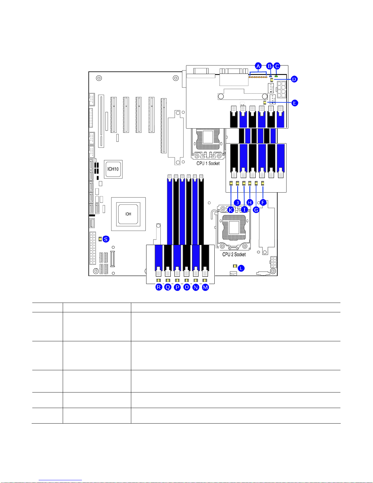
Figure 3. Server Board Connector and Component Locations...................................................15
Figure 4. Configuration Jumper Location....................................................................................16
Figure 5. Back Panel Features ...................................................................................................17
Figure 6. Intel® Light-Guided Diagnostics...................................................................................19
Figure 7. DIMM Sockets .............................................................................................................22
Figure 8. Intel® SAS Entry RAID Module ....................................................................................26
Figure 9. BIOS Recover Jumper.................................................................................................32
Figure 10. Password Clear Jumper ............................................................................................34
Figure 11. CMOS Clear Jumper .................................................................................................35
Figure 12 .Installing Memory.......................................................................................................36
Figure 13. Opening the Processor Socket Lever........................................................................38
Figure 14. Opening the Processor Socket Load Plate................................................................39
Figure 15. Removing the Processor Socket Protective Cover....................................................39
Figure 16. Remove Processor Protective Cover.........................................................................39
Figure 17. Install the processor...................................................................................................40
Figure 18. Close Load Plate and Socket Lever ..........................................................................40
Figure 19. Installing Processor Heatsink(s)................................................................................42
Figure 20. Locating Active Heatsink Cable Connections............................................................43
Figure 21. Locating and Removing the CMOS Battery...............................................................45
Tables
Table 1. Server Board Features..................................................................................................13
Table 2. Configuration Jumpers..................................................................................................16
Table 3. NIC LEDs......................................................................................................................17
Table 4. Storage Mode Matrix.....................................................................................................25
Table 5. Keyboard Commands...................................................................................................30
Table 6. Heatsink Requirements for Compatible Intel® Server Chassis .....................................41
Table 7. POST Error Beep Codes ..............................................................................................46
Table 8. BIOS POST Error Beep Codes.....................................................................................53
Table 9. BMC POST Error Beep Codes .....................................................................................53
Table 10. Product Certification Markings....................................................................................55
Intel® Server Board S5520HC and S5500HCV Service Guide xi
Page 12
Server Board Features
1 Server Board Features
This chapter briefly describes the main features of the Intel® Server Board S5520HC and Intel® Server Board
S5500HCV. This chapter provides a photograph of the product, list of the server board features, and diagrams
showing the location of important components and connections on the server board.
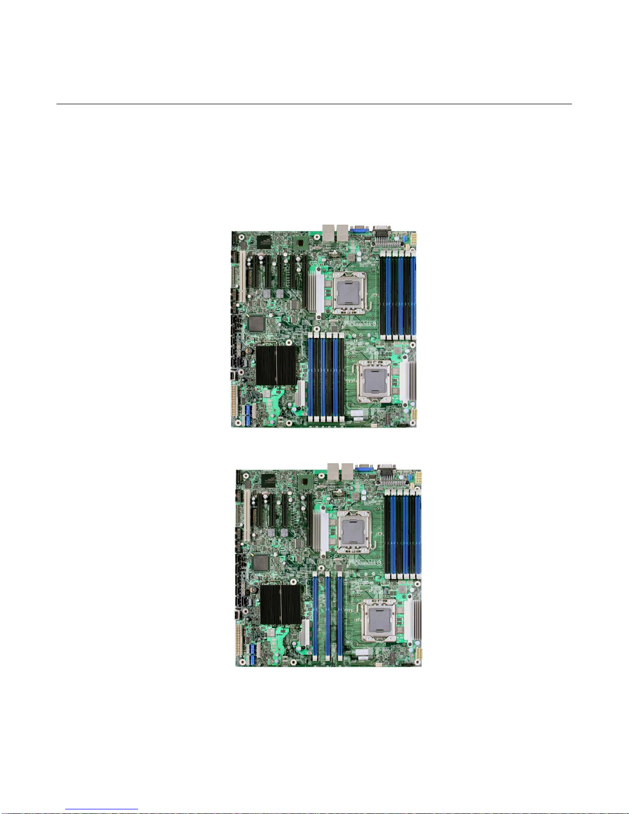
The Intel® Server Board S5520HC and Intel® Server Board S5500HC are shown in the following pictures.
Figure 1. Intel® Server Board S5520HC
Figure 2. Intel® Server Board S5500HCV
Intel® Server Board S5520HC and S5500HCV Service Guide 12
Page 13
Table 1. Server Board Features
Server Board Features
Feature Description
Processors
Up to two Intel
®
Xeon® Processors 5500 series with Thermal Design Power
(TDP) up to 95 W.
Memory
Six memory channels (three channels per processor socket) with support for
800/1066/1333 MT/s ECC Registered (RDIMM) or Unbuffered (UDIMM)
DDR3 memory.
No support for mixing of RDIMMs and UDIMMs.
®
Intel
Server Board S5520HC
o 12 DIMM slots, two DIMM slots per channel
®
Intel
Server Board S5500HCV
o Nine DIMM slots.
o Two DIMM slots on each channel of processor socket 1.
o One DIMM slot on each channel of processor socket 2.
Chipset
Intel
Server Board S5520HC
®
o Intel® S5520 Chipset and Intel® 82801Jx I/O Controller Hub
(ICH10R)
®
Intel
Server Board S5500HCV
®
o Intel
S5500 Chipset and Intel® 82801Jx I/O Controller Hub
(ICH10R)
Cooling fan support
Support for
Two processor fans (4-pin headers)
Four front fans (6-pin headers)
One rear fan (4-pin header)
3-pin fans are compatible with all fan headers.
Add-in Card Slots
Intel
Server Board S5520HC: Six expansion slots
®
o One PCI Express* Gen 2 slot (x16 Mechanically, x8 Electrically)
o Three PCI Express* Gen 2 x8 slots
o One PCI Express* Gen 1 slot (x8 Mechanically, x4 Electrically)
shared with SAS Module slot
o One 32-bit/33 MHz PCI slot, keying for 5 V and Universal PCI add-
in card
®
Intel
Server Board S5500HCV: Five expansion slots
o One PCI Express* Gen 2 slot (x16 Mechanically, x4 Electrically)
o Two PCI Express* Express* Gen 2 x8 slots
o One PCI Express* Gen 1 slot (x8 Mechanically, x4 Electrically)
shared with SAS Module slot
o One 32-bit/33 MHz PCI slot, keying for 5 V and Universal PCI add-
in card
Video Support
Server Engine* LLC Pilot II* with 64 MB DDR2 memory, 8 MB allocated to
graphics
Dual video is supported
Hard Drive and Optical
Drive Support
Optical devices are supported
Six SATA connectors at 1.5 Gbps and 3 Gbps
Four SAS connectors at 3 Gbps through optional Intel® SAS Entry RAID
Module AXX4SASMOD
Intel® Server Board S5520HC and S5500HCV Service Guide 13
Page 14
Server Board Features
USB Drive Support
I/O control support
RAID Support
Management support
One internal USB port
One internal low-profile USB port for Solid State Drive
External connections:
o DB9 serial port A connection
o One DH 10 serial port connector (optional)
o Two RJ-45 NIC connectors for 10/100/1000 Mb connections: Dual
GbE through the Intel
®
82575EB Network Connection.
o Four USB 2.0 ports at the back of the board
Internal connections:
o Two 9-pin USB headers, each supports two USB 2.0 ports
o One internal USB port that supports a peripheral, such as a floppy
drive
o One DH10 serial port B header
o Six SATA connectors at 1.5 Gbps and 3 Gbps
o Four SAS connectors at 3 Gbps (optional)
o One SSI-compliant 24-pin front control panel header
®
Intel
Embedded Server RAID Technology II through on-board SATA
connectors provides SATA RAID 0, 1, and 10 with optional RAID 5 support
provided by the Intel® RAID Activation Key AXXRAKSW5
Intel® Embedded Server RAID Technology II through optional Intel® SAS Entry
RAID Module AXX4SASMOD provides SAS RAID 0, 1, and 10 with optional
RAID 5 support provided by the Intel® RAID Activation Key AXXRAKSW5
®
IT/IR RAID through optional Intel
SAS Entry RAID Module AXX4SASMOD
provides entry hardware RAID 0, 1, 10/10E, and Native SAS pass through
mode
Integrated IPMI 2.0 compliant Baseboard Management Controller
Support for the Intel
®
Local Control Panel (optional component sold
separately)
Support for Intel
Support for Intel
®
Remote Management Module 3
®
System Management Software
Intel® Light-Guided Diagnostics on field replaceable units
Intel® Server Board S5520HC and S5500HCV Service Guide 14
Page 15
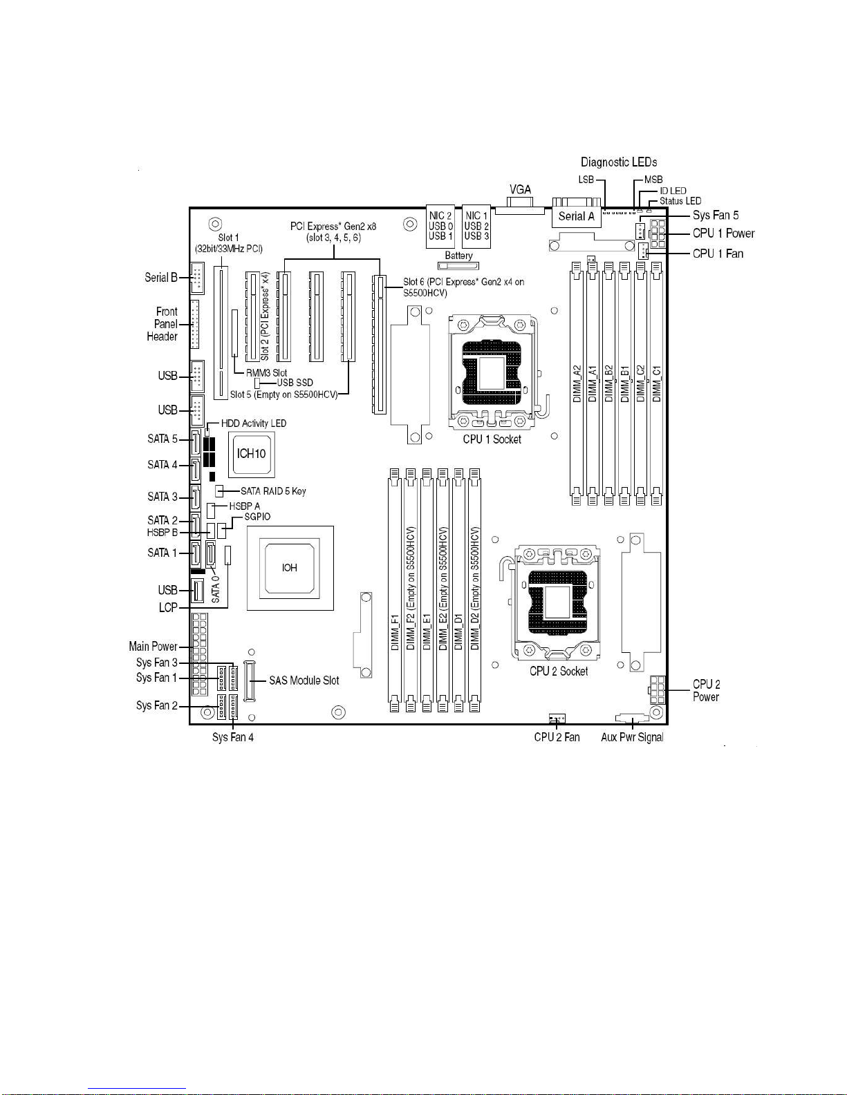
Connector and Component Locations
Server Board Features
Figure 3. Server Board Connector and Component Locations
Intel® Server Board S5520HC and S5500HCV Service Guide 15
Page 16
Server Board Features
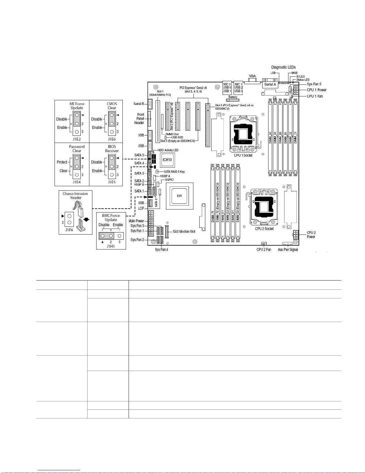
Configuration Jumpers
Figure 4. Configuration Jumper Location
Table 2. Configuration Jumpers
Jumper Name Pins What happens at system reset…
CMOS Clear
(J1E6)
ME Force Update
(J1E2)
Password Clear
(J1E4)
BIOS Recover
(J1E5)
1-2 (Default)
2-3 If pins 2-3 are connected for 5 to 10 seconds with AC power unplugged, the CMOS
1-2 (Default)
2-3 ME Firmware Force Update Mode – Enabled
1-2 (Default)
2-3 To clear administrator and user passwords, power on the system with pins 2-3
1-2 (Default)
2-3 The main system BIOS does not boot with pins 2-3 connected. The system only boots
Protect CMOS: These pins should have a jumper in place for normal system operation.
settings clear on the next reset.
These pins should not be connected for normal operation.
ME Firmware Force Update Mode – Disabled
These pins should have a jumper in place for normal system operation.
These pins should not be connected for normal operation.
Protect Password: These pins should have a jumper in place for normal system
operation.
connected. The administrator and user passwords clear in 5-10 seconds after power
on.
These pin should not be connected for normal system operation.
These pins should be connected for normal system operation.
Intel® Server Board S5520HC and S5500HCV Service Guide 16
Page 17
from EFI-bootable recovery media with a recovery BIOS image present.
These pin should not be connected for normal system operation.
BMC Force
Update
(J1H1)
1-2 (Default) BMC Firmware Force Update Mode – Disabled.
These pins should have a jumper in place for normal system operation.
2-3 BMC Firmware Force Update Mode – Enabled.
These pins should not be connected for normal operation.
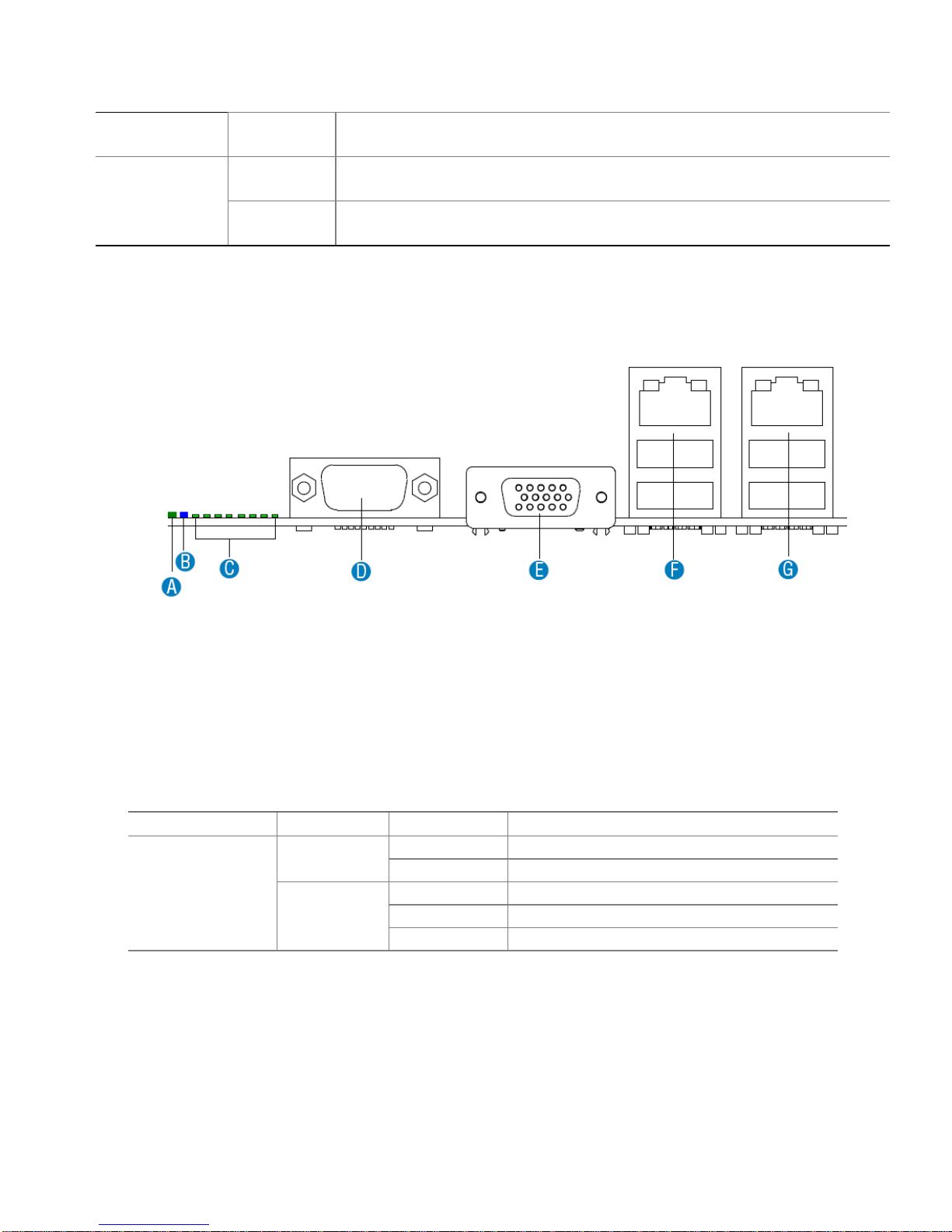
Back Panel Features
Server Board Features
A. System Status LED E. Video
B. ID LED F. NIC 1 (top, default management port), Two USB (bottom)
C. POST Diagnostic LEDs G. NIC 2 (top), Two USB (bottom)
D. Serial A Port
Figure 5. Back Panel Features
The NIC LEDs at the right and left of each NIC provide the following information:
Table 3. NIC LEDs
NIC LED Color LED State Description
NIC 1 and NIC 2
(Gigabit)
Left LED
Right LED
Off No network connection
Blinking Green Transmit/receive activity
Off 10 Mbps connection (if left LED is on or blinking)
Solid Green 100 Mbps connection
Solid Amber 1000 Mbps connection
Intel® Server Board S5520HC and S5500HCV Service Guide 17
Page 18
Server Board Features
Intel® Light-Guided Diagnostics
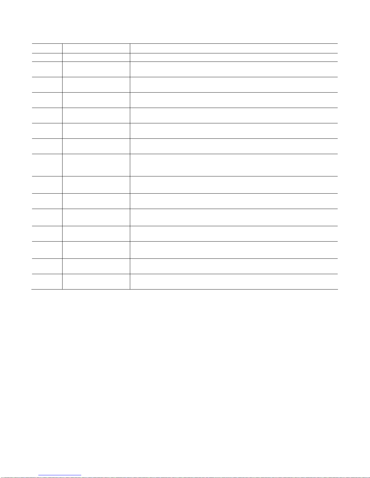
Callout LED Functions
A. POST Diagnostics LEDs POST Diagnostics LEDs: The sequence of lit POST Diagnostics LEDs is used to
identify specific errors that might occur during the boot process. For a description of
how to read these LEDs, refer to the appendix of the Technical Product
Specification.
B. ID LED You can turn this LED on and off by pressing a chassis button or by using system
management software. This LED is useful when the system is grouped with several
systems, such as in a rack, and you need to find the system to perform
maintenance on it.
C. System Status LED The status LED indicates whether a system is operating correctly, has experienced
a minor fault, or a major system error. For details about this LED, refer to the
Technical Production Specification.
D. System fan 5 fault LED This LED indicates a fault occurred with a fan installed on the Server Board System
Fan 5 header. Replace the faulty unit.
E. Processor 1 fan fault
LED
This LED applies only to server systems that use an active heatsink. This LED
indicates a fault occurred with the fan installed on the heatsink for processor 1.
Intel® Server Board S5520HC and S5500HCV Service Guide 18
Page 19
Server Board Features
Callout LED Functions
Replace faulty unit.
F. DIMM C1 fault LED This LED indicates a fault occurred with the DIMM installed in socket DIMM_C1.
Replace the faulty DIMM.
G. DIMM C2 fault LED This LED indic ates a fault occurred with the DIMM installed in socket DIMM_C2.
Replace the faulty DIMM.
H. DIMM B1 fault LED This LED indicates a fault occurred with the DIMM installed in socket DIMM_B1.
Replace the faulty DIMM.
I. DIMM B2 fault LED This LED indicates a fault occurred with the DIMM installed in socket DIMM_B2.
Replace the faulty DIMM.
J. DIMM A1 fault LED This LED indicates a fault occurred with the DIMM installed in socket DIMM_A1.
Replace the faulty DIMM.
K. DIMM A2 fault LED This LED indicates a fault occurred with the DIMM installed in socket DIMM_A2.
Replace the faulty DIMM.
L. Processor 2 fan fault
LED
This LED applies only to server systems that use an active heatsink. This LED
indicates a fault occurred with a fan installed on the heatsink for processor 2.
Replace faulty unit.
M. DIMM D2 fault LED
(Empty in S5500HCV)
This LED indicates a fault occurred with the DIMM installed in socket DIMM_D2.
Replace the faulty DIMM.
N. DIMM D1 fault LED This LED indicates a fault occurred with the DIMM installed in socket DIMM_D1.
Replace the faulty DIMM.
O. DIMM E2 fault LED
(Empty in S5500HCV)
This LED indicates a fault has occurred with the DIMM installed in socket
DIMM_E2. Replace the faulty DIMM.
P. DIMM E1 fault LED This LED indicates a fault occurred with the DIMM installed in socket DIMM_E1.
Replace the faulty DIMM.
Q. DIMM F2 fault LED
(Empty in S5500HCV)
This LED indicates a fault occurred with the DIMM installed in socket DIMM_F2.
Replace the faulty DIMM.
R. DIMM F1 fault LED This LED indicates a fault occurred with the DIMM installed in socket DIMM_F1.
Replace the faulty DIMM.
S. +5-V Standby LED This LED is green whenever AC power is applied to the system. You do not need to
power on the system for this LED to be on.
Figure 6. Intel® Light-Guided Diagnostics
RAID Support
The Intel® Server Board S5520HC / S5500HCV provide an embedded SATA controller that supports bot h 1.5 Gbps
and 3.0 Gbps data transfer rates.
The BIOS Setup Utility provides drive configuration options on the Advanced | Mass Storage Controller Configuration
setup page, some of which affect the ability to configure RAID. The “On-board SATA Controller” option is enabled by
default and when enabled, you can set the “SATA Mode” option to either one of the following fo ur modes:
“Enhanced” – Enhanced Mode supports up to six SATA ports with IDE native Mode.
“Compatibility” – Supports up to four SATA ports [0/1/2/3] with IDE Legacy mode and two SATA ports [4/5] with
IDE Native Mode.
“AHCI” – Supports all SATA ports using the Advanced Host Controller Interface.
Intel® Server Board S5520HC and S5500HCV Service Guide 19
Page 20

Server Board Features
“SW RAID” – Intel
Embedded Server RAID Technology II feature provides RAID modes 0, 1, and 10.
If RAID 5 is needed, you must install the optional Intel
key is placed on the SATA_ RAID_5_Key connector located on the left side of the server board. For installation
instructions, see the documentation included with the activation key.
®
When Intel
management is provided through the SATA_SGPIO connector on the server board when a cable is attached bet ween
this connector and the backplane or I
NOTE
For help with navigating the BIOS Setup utility, see the Intel® Server Board S5520HC/S5500HCV Technical Product
Specification.
For information on how to configure RAID, refer to the RAID software user’s guide at:
http://www.intel.com/support/motherboards/server/S5520HC/howto.htm
For help with enclosure management cabling, refer to the Enclosure Management Cabling Guide for Pedestal
Systems with hot-swap Drive Backplanes. This guide is available at:
http://support.intel.com/support/motherboards/server/S5520HC/compat.htm
Embedded Server RAID Technology II is enabled with the embedded SATA controller, encl osure
®
Embedded Server RAID Technology II is enabled by “SW RAID” mode. The Intel®
®
RAID Activation Key AXXRAKSW5 accessory. This activation
2
C interface.
Hardware Requirements
To avoid integration difficulties and possible board damage, your system must meet the following requirements
outlined. For a list of qualified components, see the links under “Additional Information and Software”.
Processor
One or two Intel® Xeon® Processor 5500 series.
For a list of supported processors, see the links under “Additional Information and Software”.
You must populate processors in sequential order. Therefore, you must populate Processor Socket 1 (CPU 1) before
processor socket 2 (CPU 2).
For optimum performance, when two processors are installed, both must be the identical revision and h ave the same
core voltage and Intel
Memory
The Intel® Server Board S5520HC provides 12 DIMM sockets in six channels. Each channel contains two DIMM
sockets:
Channel A contains DIMM sockets A1 and A2
Channel B contains DIMM sockets B1 and B2
®
QPI / Core speed.
Channel C contains DIMM sockets C1 and C2
Intel® Server Board S5520HC and S5500HCV Service Guide 20
Page 21

Server Board Features
Channel D contains DIMM sockets D1 and D2
Channel E contains DIMM sockets E1 and E2
Channel F contains DIMM sockets F1 and F2
The Intel® Server Board S5520HCV provides nine DIMM sockets in six channels. Channels A, B, and C contain two
DIMM sockets per channel. Channels D, E, and F contain one DIMM socket per channel:
Channel A contains DIMM sockets A1 and A2
Channel B contains DIMM sockets B1 and B2
Channel C contains DIMM sockets C1 and C2
Channel D contains DIMM sockets D1
Channel E contains DIMM sockets E1
Channel F contains DIMM sockets F1
Callout DIMM Socket Callout DIMM Socket
A. Channel A, DIMM_A2 G. Channel D, DIMM_D2 (Empty on S5500HCV)
B. Channel A, DIMM_A1 (Blue) H. Channel D, DIMM_D1 (Blue)
C. Channel B, DIMM_B2 I. Channel E, DIMM_E2 (Empty on S5500HCV)
Intel® Server Board S5520HC and S5500HCV Service Guide 21
Page 22

Server Board Features
D. Channel B, DIMM_B1 (Blue) J. Channel E, DIMM_E1 (Blue)
E. Channel C, DIMM_C2 K. Channel F, DIMM_F2 (Empty on S 5500HCV)
F. Channel C, DIMM_C1 (Blue) L. Channel F, DIMM_F1 (Blue)
Figure 7. DIMM Sockets
DDR3 DIMMs must meet the following requirements:
Use only 240-pin DDR3 DIMMs.
A minimum of one 1 GB DDR3 DIMM is required in DIMM socket DIMM_A1.
Either registered DDR3 DIMMs (RDIMMs) or unbuffered ECC/non-ECC DDR3 DIMMs (UDIMMs). No mixing of
RDIMMs and UDIMMs.
DDR3-800, DDR3-1066, or DDR3-1333
DIMM within a channel must be populated starting with the first slot (blue slot) of the channel: DIMM_A1,
DIMM_B1, DIMM_C1, DIMM_D1, DIMM_E1, or DIMM_F1.
When installing Quad-rank DIMM, you must populate Quad-rank DIMM starting with the first slot (blue slot) of
each channel.
For a complete list of supported memory DIMMs, see the links under “Additional Information and Software”.
Channel Population Requirements for Memory RAS Modes
The Intel® Server Board S5520HC / S5500HCV support two memory RAS modes: Independent Channel Mode, and
Mirrored Channel Mode. The rules on channel population and channel matching vary by the RAS mode used. Note
that the support of RAS modes that require matching DIMM population between channels (Mirroring) and require that
ECC DIMMs must be populated. Independent Mode is the only mode that supports non-ECC DIMMs in addition to
ECC DIMMs.
Independent Channel Mode
You can populate channels in any order in Independent Channel Mode. You can populate all three channels in any
order and have no matching requirements. All channels must run at the same interface frequency, but individual
channels may run at different DIMM timings (RAS latency, CAS latency, and so on).
Mirrored Channel Mode
In Mirrored Channel Mode, the memory contents are mirrored between Channels A (D) and Chann el B (E). As a result
of the mirroring, the total physical memory available to the system is half of what is populated. Mirrored Channel Mode
requires that Channel A (D) and Channel B (E) must be populated identically. DIMM slot populations within a channel
do not have to be identical but the same DIMM slot location across Channel A (D) and Channel B (E) must be
populated the same. Channel C (F) is unused in Mirrored Channel Mode.
NOTE
For help with memory population rules, refer to the Intel® Server Board S5520HC/S5500HCV Technical Product
Specification.
Intel® Server Board S5520HC and S5500HCV Service Guide 22
Page 23

Server Board Features
Power Supply
A minimum of 550 W is required. Your supply must provide a minimum of 3 amps of 5-V standby current or the board
will not boot.
Intel® Server Board S5520HC and S5500HCV Service Guide 23
Page 24

Server Board Features
Intel® Server Board S5520HC and S5500HCV Service Guide 24
Storage Mode Matrix
SW RAID = Intel® Embedded Server RAID Technology II (ESRTII)
IT/IR RAID = IT/IR RAID, Entry Hardware RAID
Storage
Controller
Storage
Mode
Description
RAID Types and Levels
Supported
Driver
RAID
Management
Software
RAID
Software
User’s Guide
Compatible
Backplane
Enhanced
6 SATA ports at
Native mode
N/A
Chipset
driver or
operating
system
embedded
Broad OS
support
N/A N/A
Compatibility
6 SATA ports: port 0,
1, 2, 3 at IDE Legacy
mode, port 4, 5 at
Native mode
N/A
Chipset
driver or
operating
system
embedded
Broad OS
Support
N/A N/A
AHCI
6 SATA ports using
the Advanced Host
Controller Interface
N/A
AHCI driver
or OS
embedded
Broad OS
Support
N/A N/A
Onboard SATA
Controller
(ICH10R)
SW RAID 6 SATA Ports
SW RAID 0/1/10 standard
SW RAID 5 with optional
AXXRAKSW5
ESRTII
Driver
Microsoft
Windows*
and
selected
Linux*
Versions
only
Intel
®
RAID
Web Console
2
Intel® RAID
Software
User’s Guide
AXX6DRV3GR,
AXX4DRV3GR
Page 25

Server Board Features
Intel® Server Board S5520HC and S5500HCV Service Guide 25
Storage
Controller
Storage
Mode
Description
RAID Types and Levels
Supported
Driver
RAID
Management
Software
RAID
Software
User’s Guide
Compatible
Backplane
IT/IR RAID
4 SAS Ports
Up to 10 SAS or SATA
drives via expander
backplanes
Native SAS pass through
mode without RAID
function.
Entry Hardware RAID.
- RAID 1 (IM mode)
- RAID 10/10E (IME
mode)
- RAID 0 (IS Mode)
SAS MPT
driver (Fully
opensource
driver)
Broad OS
support.
Intel
®
RAID
Web Console
2
IT/IR RAID
Software
User’s Guide
Optional Intel®
SAS Entry RAID
module
AXX4SASMOD
SW RAID
4 SAS Ports
Up to 8 SAS or SATA
drives via expander
backplanes
SW RAID 0/1/10 standard
SW RAID 5 with optional
AXXRAKSW5
Microsoft Windows* and
selected Linux* Versions
only
ESRTII
Driver
Intel
®
RAID
Web Console
2
Intel
®
RAID
Software
User’s Guide
AXX6DRV3GR
AXX4DRV3GR
AXX6DRV3GEXP
AXX4DRV3GEXP
Table 4. Storage Mode Matrix
Page 26

Server Board Features
Optional Hardware
Intel® SAS Entry RAID Module AXX4SASMOD
The Intel® Server Board S5520HC / S5500HCV provide a SAS module slot (J2J1) for the installation of an optional
Intel® SAS Entry RAID Module AXX4SASMOD. Once the optional Intel® SAS Entry RAID Module AXX4SASMOD is
present, the x4 PCI Express* links from the ICH10R to PCI Express* Slot 2 (x8 mechanically, x4 electrically) switches
to the SAS module slot.
®
The optional Intel
Express* link widths and is a single-function PCI Express* end-point device. The SAS controller supports the SAS
protocol as described in the Serial Attached SCSI (SAS) Standard, version 1.0, and also supports SAS 1.1 features. A
32-bit external memory bus off the SAS1064e controller provides an interface for Flash ROM and NVSRAM (Nonvolatile Static Random Access Memory) devices.
The optional Intel
drives with a non-expander backplane or up to eight hard drives with an expander backplane.
The optional Intel
Output) connector and a SCSI Enclosure Services (SES) connector for backplane drive LED control.
SAS Entry RAID Module AXX4SASMOD includes a SAS1064e controller that supports x4 PCI
®
SAS Entry RAID Module AXX4SASMOD provides four SAS connectors that support up to four hard
®
SAS Entry RAID Module AXX4SASMOD also provides a SGPIO (Serial General Purpose Input /
SAS RAID Support
The BIOS Setup Utility provides drive configuration options on the Advanced | Mass Storage Controller Configuration
setup page for the Intel
®
The “Intel
AXX4SASMOD is present. When enabled, you can set the “Configure Intel
Integrated RAID” or “Intel
Intel® Server Board S5520HC and S5500HCV Service Guide 26
SAS Entry RAID Module” option is enabled by default once the Intel® SAS Entry RAID Module
®
SAS Entry RAID Module AXX4SASMOD, some of which affect the ability to configure RAID.
®
ESRTII” mode.
Figure 8. Intel® SAS Entry RAID Module
®
SAS Entry RAID Module” to either “LSI*
Page 27

Server Board Features
IT/IR RAID Mode
Supports entry hardware RAID 0, RAID 1, and RAID10/10E and native SAS pass through mode.
Intel® ESRTII Mode
The Intel® Embedded Server RAID Technology II (Intel® ESRTII) feature provides RAID modes 0, 1, and 10. If RAID 5
is needed with Intel® ESRTII, you must install the optional Intel® RAID Activation Key AXXRAKSW5 accessory. This
activation key is placed on the SAS Software RAID 5 connector located on the Intel
AXX4SASMOD. For installation instructions, see the documentation included with the SAS Module AXX4SASMOD
and the activation key.
®
When Intel
Embedded Server RAID Technology II is enabled with the SAS Module AXX4SASMOD, enclosure
management is provided through the SAS_SGPIO or SES connector on the SAS Module AXX4SASMOD when a
2
cable is attached between this connector and the backplane or I
NOTE
C interface.
For help with navigating the BIOS Setup utility, refer to the Intel® Server Board S5520HC/S5500HCV Technical
Product Specification.
®
SAS Entry RAID Module
For information on how to configure RAID, see the RAID software user’s guide at:
http://www.intel.com/support/motherboards/server/S5520HC/howto.htm
For information about configure IT/IR RAID, see the IT/IR RAID software user’s guide at:
http://www.intel.com/support/motherboards/server/S5520HC/howto.htm
For help with enclosure management cabling, see the Enclosure Management Cabling Guide for Pedestal Systems
with Hot-swap Drive Backplanes. This guide is available at:
http://support.intel.com/support/motherboards/server/S5520HC/compat.htm
Intel® RAID Activation Key
You can purchase and install the Intel® RAID Activation Key AXXRAKSW5 to enable Software RAID 5 support on your
server board or the Intel® SAS Entry RAID Module AXX4SASMOD. For the Intel® Server Board S5520HC / S5500HCV,
®
you can install an Intel
Entry RAID Module AXX4SASMOD, you can install an Intel
RAID Activation Key (AXXRAKSW5) in the SATA RAID 5 Key connector. For the Intel® SAS
®
RAID Activation Key (AXXRAKSW5) in the SAS RAID 5
key connector of the SAS module card.
Hard Disk Drives
The Intel® Server Board S5520HC / S5500HCV support different hard disk driver options.
USB or Serial SATA (SATA) Solid State Drives
Serial SATA (SATA) and Serial Attached SCSI (SAS):
– Supports for SATA Hard Disk Drive: Six on- board SATA ports at 1.5 Gbps and 3 Gbps.
– Supports for SAS or SATA Hard Disk Drives: Four SAS ports via optional Intel
AXX4SASMOD at 1.5 Gbps (SATA) and 3 Gbps (SATA and SAS).
Intel® Server Board S5520HC and S5500HCV Service Guide 27
®
SAS Entry RAID Module
Page 28

Server Board Features
NOTE
Refer to the documentation included with your server chassis for additional information and drive installation
instructions.
Tower Passive Heatsink (FXXRGTHSINK)
This tower passive heatsink (FXXRGTHSINK) is required when installing the Intel® Server Board S5520HC /
S5500HCV into the Intel® Server Chassis SC5600LX. Two tower heatsinks are required for dual-processor installation.
®
This tower passive heatsink is NOT required for other Intel
Intel® Server Chassis SC5650 families.
Server Chassis in the Intel® Server Chassis SC5600 and
Intel® Remote Management Module 3
The Intel® Remote Management Module 3 (RMM3) plugs into the connector on the server board and acts as a
component of the server board, and provides a way to view and operate the server remotely in real-time. Keyboard,
video, and mouse control (KVM) is redirected to a managing system. This provides remote control. USB media
redirection allows you to use a USB device anywhere on the network as if it was installed on the management server
with RMM3 installed. For example, you can insert a CD-ROM disk in a workstation CD-ROM drive and the managed
server views it as its own, local CD-ROM drive.
Intel® Local Control Panel
The Intel® Local Control Panel provides enhanced system control by using a LCD display, which provides add itional
controls and indicators beyond the standard control panel.
Intel® Server Board S5520HC and S5500HCV Service Guide 28
Page 29

System Utilities
2 System Utilities
Using the BIOS Setup Utility
This section describes the BIOS Setup Utility options, which you use to change server configur ation defaults. You can
run the BIOS Setup with or without an operating system present. See “Additional Information and Software” for a link
to the Technical Product Specification where you can find details about specific BIOS setup screens.
Starting Setup
You can enter and start BIOS Setup under several conditions:
When you turn on the server, after POST completes the memory test.
When you move the CMOS jumper on the server board to the “Clear CMOS” position (enabled).
In the two conditions listed above, after rebooting, you will see this prompt:
Press <F2> to enter SETUP
In a third condition, when CMOS/NVRAM is corrupted, you will see other prompts but not the <F2> prompt:
Warning: CMOS checksum invalid
Warning: CMOS time and date not set
In this condition, the BIOS loads the default values for CMOS and attempts to boot.
If You Cannot Access Setup
If you cannot access the BIOS Setup, you might need to clear the CMOS memory. For instructions on clearing the
CMOS, see “Clearing the CMOS”.
Setup Menus
Each BIOS Setup menu page contains a number of features. Except for those features provided only to display
automatically configured information, each feature is associated with a value field that contains user-selectable
parameters. If they have adequate security rights, a user can change these parameters. If a value cannot be changed
for any reason, the feature’s value field is inaccessible.
Table 5 describes the keyboard commands you can use in the BIOS Setup menus.
®
Intel
Server Board S5520HC and S5500HCV Service Guide 29
Page 30

System Utilities
Press Description
<F1> Help - Pressing F1 on any menu opens the general Help window.
F5/- Change Value - The minus key or the F5 function key is used to change the value of the current item
F6/+ Change Value - The plus key or the F6 function key is used to change the value of the current menu
<Enter> Execute Command - The Enter key is used to activate submenus when the selected feature is a
<Esc> Exit - The ESC key provides a mechanism for backing out of any field. This key will undo the
<F9> Setup Defaults - Pressing F9 causes the following to display:
<F10> Save and Exit - Pressing F10 causes the following message to displ ay:
Table 5. Keyboard Commands
The left and right arrow keys are used to move between the major menu pages. The keys have no
effect if a submenu or pick list is displayed.
Select Item up - The up arrow is used to select the previous value in a menu item’s option list, or a
value field pick list. Pressing the Enter key activates the selected item.
Select Item down - The down arrow is used to select the next value in a menu item’s option list, or a
value field pick list. Pressing the Enter key activates the selected item.
to the previous value. This key scrolls through the values in the associated pick list without displaying
the full list.
item to the next value. This key scrolls through the values in the associated pick list without
displaying the full list. On 106-key Japanese keyboards, the plus key has a different scan code than
the plus key on the other keyboard, but it has the same effect.
submenu, or to display a pick list if a selected feature has a value field, or to select a sub-field for
multi-valued features like time and date. If a pick list is displayed, the Enter key will undo the pick list,
and allow another selection in the parent menu.
pressing of the Enter key. When the ESC key is pressed while editing any field or selecting features
of a menu, the parent menu is re-entered. When the ESC key is pressed in any submenu, the parent
menu is re-entered. When the ESC key is pressed in any major menu, the exit confirmation window
is displayed and the user is asked whether they want to discard their changes.
Setup Confirmation
Load default configuration now?
[Yes] [No]
If “Yes” is selected and the Enter key is pressed, all Setup fields are set to their default values. If “No”
is selected and the Enter key is pressed, or if the ESC key is pressed, the user is returned to where
they were before F9 was pressed without affecting any existing field values.
Setup Confirmation
Save Configuration changes and exit now?
[Yes] [NO]
If “Yes” is selected and the Enter key is pressed, all changes are saved and Setup is exited. If “No”
is selected and the Enter key is pressed, or if the ESC key is pressed, the user is returned to where
they were before F10 was pressed without affecting any existing values.
Upgrading the BIOS
The upgrade utility allows you to upgrade the BIOS in flash memory. The code and data i n the upgrade file include the
following:
On-board BIOS, including the recovery code, BIOS Setup Utility, and strings
On-board video BIOS and other option ROMs for devices embedded on the server board
OEM binary area
Processor Microcode
Intel® Server Board S5520HC and S5500HCV Service Guide 30
Page 31

A way to change the BIOS language
Option ROM of the Intel® Embedded Server RAID Technology II for on-board SATA
Preparing for the Upgrade
The following steps explain how to prepare to upgrade the BIOS and include how to:
Record the current BIOS settings
Obtain the upgrade utility
Prepare a storage media for the utility
System Utilities
NOTE
In the unlikely event a BIOS error occurs during the BIOS update process, you may need to follow a recovery
process to return the system to service. See “Recovering the BIOS” for instructions on performing a BIOS
recovery.
Recording the Current BIOS Settings
1. Boot the computer and press <F2> when you see the message:
Press <F2> Key if you want to run SETUP
2. Write down the current settings in the BIOS Setup program or use the “Save and Store System Configuration
Utility (SYSCFG)” to save the current settings into a file. See “Additional Information and Software” for a link to the
utility and instructions.
NOTE
Do not skip Step 2. You need these settings to configure your computer at the end of the procedure.
Obtaining the Upgrade
Download the BIOS image file to a temporary folder on your hard drive. See “Additional Information and Software” for
a link to the update software.
NOTE
Before attempting a BIOS upgrade, review the instructions distributed with the upgrade utility. Review also any
release notes in the release notes file that accompanies the new version of the BIOS. The release notes may
contain critical information regarding jumper settings, specific fixes, or other information to complete the
upgrade.
Updating the BIOS
Follow the instructions in the readme file that came with the BIOS upgrade software package. When the updates
complete, remove the storage media from which you performed the upgrade.
CAUTIONS
Do not power down the system during the BIOS update process!
®
Intel
Server Board S5520HC and S5500HCV Service Guide 31
Page 32

System Utilities
NOTE
You may encounter a CMOS Checksum error or other problem after reboot. If this happens, shut down the
system and boot it again. CMOS checksum errors require that you enter Setup, check your settings, save
your settings, and exit Setup.
Recovering the BIOS
In the rare event the BIOS becomes damaged, you may need to follow a recovery process to return the system to
service. To place the baseboard into recovery mode, move the BIOS Recover jumper (J1E5) located on the
baseboard to the recovery position. The BIOS can then execute the recovery instead of the normal BIOS.
BIOS Recovery Procedure
NOTE
The BIOS recovery is the mode of last resort; it is used only when the main system BIOS will not come up.
1. Download the BIOS image file to a temporary folder on your hard drive. See “Additional Information and
Software” for a link to the update software.
2. Copy all the files in the BIOS recovery package to the root directory of a USB disk-on-key device.
3. Power off the system.
4. Switch the BIOS recovery jumper (J1E5) to the “enabled” position (ping 2-3).
Intel® Server Board S5520HC and S5500HCV Service Guide 32
Figure 9. BIOS Recover Jumper
Page 33

System Utilities
5. Insert the recovery media and confirm all the recovery files in the media.
6. Power on the system.
7. The BIOS POST screen will appear displaying the progress, and the system automatically boots to the EFI
SHELL.
8. Startup.nsh file executes automatically, and initiates the BIOS update with the recovery BIOS capsule file. The
message of the “BIOS has been updated successfully” displays once the recovery process is complete.
9. Power off the system and revert the BIOS recovery jumper position to the default (pin 1-2).
10. Power on the system.
CAUTIONS
DO NOT interrupt the BIOS POST during the first boot after recovery!
Clearing the Password
If the user or administrator password(s) is lost or forgotten, moving the password clear jumper into the “clear” position
clears both passwords. You must restore the password clear jumper to its original position before you can set a new
password(s). The password clear jumper is located on jumper block J1E4.
1. Power down the server. Do not disconnect the power cord.
2. Open the chassis. For instructions, see your server chassis documentation.
3. Move the jumper (J1E4) from the default operating position, covering pins 1 and 2, to the password clear
position, covering pins 2 and 3.
®
Intel
Server Board S5520HC and S5500HCV Service Guide 33
Page 34

System Utilities
Figure 10. Password Clear Jumper
4. Close the server chassis.
5. Power up the server and then press <F2> to enter the BIOS menu to check if the password is cleared.
6. Power down the server.
7. Open the chassis and move the jumper back to its default position, covering pins 1 and 2.
8. Close the server chassis.
9. Power up the server.
The password is now cleared and you can reset it by going into the BIOS setup.
Intel® Server Board S5520HC and S5500HCV Service Guide 34
Page 35

System Utilities
Clearing the CMOS
If you cannot access the BIOS setup screens, you must use the CMOS Clear jumper to reset the configuration RAM.
The CMOS Clear jumper is located on jumper block J1E6.
Figure 11. CMOS Clear Jumper
1. Power down the server and unplug the AC power cord.
2. Open the server chassis. For instructions, see your server chassis documentation.
3. Move the jumper (J1E6) from the default operating position (covering pins 1 and 2) to the reset / clear
position (covering pins 2 and 3).
4. Wait 5 - 10 seconds.
5. Move the jumper back to default position, covering pins 1 and 2.
6. Close the server chassis and reconnect the AC power cord.
7. Power up the server.
The CMOS is now cleared and you can reset it by going into the BIOS setup.
®
Intel
Server Board S5520HC and S5500HCV Service Guide 35
Page 36

Hardware Installations and Upgrades
3 Hardware Installations and Upgrades
Before You Begin
Before working with your server product, pay close attention to “Safety Information”.
Tools and Supplies Needed
Phillips* (cross head) screwdriver (#1 bit and #2 bit)
Needle nosed pliers
Antistatic wrist strap and conductive foam pad (recommended)
Installing and Removing Memory
The silkscreen on the board for the DDR3 DIMM sockets displays DIMM_A1, DIMM_A2, DIMM_B1, DIMM_B2,
DIMM_C1, DIMM_C2, DIMM_D1, DIMM_D2, DIMM_E1, DIMM_E2, DIMM_F1, and DIMM_F2, starting from the inside
of the board. See “Memory” for a discussion on memory installation rules, requirements, and options. See “Additional
Information and Software”.
Installing DIMMs
To install DIMMs, follow these steps:
1. Observe the safety and ESD precautions at the beginning of this book. For more information, see “Safety
Information”.
2. Turn off all peripheral devices connected to the server and turn off the server.
3. Disconnect the AC power cord from the server.
4. Remove the server’s cover and locate the DIMM sockets. See “Memory”.
Intel® Server Board S5520HC and S5500HCV Service Guide 36
Figure 12 .Installing Memory
Page 37

Hardware Installations and Upgrades
5. Make sure the clips at either end of the DIMM socket(s) are pushed outward to the open position (Step “A” in
Figure 12).
6. Holding the DIMM by the edges, remove it from its anti-static package.
7. Position the DIMM above the socket. Align the small notch in the bottom edge of the DIMM with the key in the
socket (Step “B” in Figure 12).
8. Insert the bottom edge of the DIMM into the socket (Step “C” in Figure 12).
9. When the DIMM is inserted, push down on the top edge of the DIMM until the retaining clips snap i nto place (Step
“D” in Figure 12).
10. Visually check that each latch is fully closed and correctly engaged with each DIMM edge slot (Step “E” in F igure
12).
11. Replace the server’s cover and reconnect the AC power cord.
Removing DIMMs
To remove a DIMM, follow these steps:
1. Observe the safety and ESD precautions at the beginning of this book. For more information, see “Safety
Information”.
2. Turn off all peripheral devices connected to the server, and turn off the server.
3. Remove the AC power cord from the server.
4. Remove the server’s cover.
5. Gently spread the retaining clips at each end of the socket. The DIMM lifts from the socket.
6. Holding the DIMM by the edges, lift it from the socket, and store it in an anti-static package.
7. Reinstall and reconnect any parts you removed or disconnected to reach the DIMM sockets.
8. Replace the server’s cover and reconnect the AC power cord.
Installing or Replacing the Processor
Intel
NOTE
Use the following instructions to install or replace a processor instead of using the instructions
that came with the processor.
CAUTION
Processor must be appropriate: If you install a processor that is inappropriate for
your server, you may damage the server board. See “Additional Information and Software”
a link to the list of compatible processor(s).
ESD and handling processors:
damage to the processor by doing the following: (1) Touch the metal chassis before touching
the processor or server board. Keep a part of your body in contact with the metal chassis to
dissipate the static charge while handling the processor. (2) Avoid moving around
unnecessarily.
®
Server Board S5520HC and S5500HCV Service Guide 37
Reduce the risk of electrostatic discharge (ESD)
for
Page 38

Hardware Installations and Upgrades
Installing the Processor
To install a processor, follow these instructions:
NOTE
You must install processors in order. Therefore, you must populate CPU 1 socket to operate
the board and to enable CPU 2 socket.
CAUTION
When opening a processor socket, DO NOT touch the gold socket wires.
When unpacking a processor, hold by the edges only to avoid touchin g the gol d contact wires.
1. Observe the safety and ESD precautions at the beginning of this book. See “Safety Information”
information.
2. Turn off all peripheral devices connected to the server and turn off the server.
3. Disconnect the AC power cord from the server.
4. Remove the server’s cover. See the document that came with your server chassis for instructions on removing
the server’s cover.
5. Locate the processor socket, push the lever handle down and away from the socket to release it (Step “A” in
Figure 13), and rotate the lever open all the way (Step “B” in Figure 13).
for more
Figure 13. Opening the Processor Socket Lever
6. Open the load plate: push the rear tab with your fingertip to bring the front end of the load plate up slightly (Step
“A” in Figure 14), and then open the load plate as shown in Figure 14 (Step “B”).
Intel® Server Board S5520HC and S5500HCV Service Guide 38
Page 39

Hardware Installations and Upgrades
Figure 14. Opening the Processor Socket Load Plate
7. Remove the processor socket protective cover: Grasp the socket protective cover by the two tabs and carefully lift
it straight up as shown in Figure 15.
8. Save the protective cover.
Figure 15. Removing the Processor Socket Protective Cover
CAUTION
To avoid damage, DO NOT drop the cover onto the socket wires or components.
9. Take the processor out of the box and remove the protective shipping cover as shown in Figure 16.
Figure 16. Remove Processor Protective Cover
10. Orient the processor with the socket so the processor cutouts match the two socket pins and then sit the
processor into the socket as shown in Figure 17.
®
Intel
Server Board S5520HC and S5500HCV Service Guide 39
Page 40

Hardware Installations and Upgrades
Figure 17. Install the processor
11. Close the load plate and socket lever: Close the load plate all the way as shown in Figure 18 (Step “A”), push
down on the load plate (Step “B” in Figure 18), and close the socket lever and ensure the load plate tab engages
under the socket lever when fully closed (Step “C” in Figure 18).
Figure 18. Close Load Plate and Socket Lever
12. Install the heatsink(s). See “Installing the Processor Heatsin k(s)” for instructions.
Installing the Processor Heatsink(s)
Selecting Processor Heatsink(s)
Each processor requires a heatsink. Depending on your chassis, you may need to use either an active or a passive
heatsink. An active heatsink has a fan attached to the heatsink and a cable that must be connected to the server
board. The following table shows the Intel
chassis requires an active or a passive heatsink. For a non-Intel chassis, see the documentation that came with your
chassis.
®
Server Chassis compatible with this server board and whether each
Intel® Server Board S5520HC and S5500HCV Service Guide 40
Page 41

®
Server
Intel
Board S5520HC /
S5500HCV
Y SC5600Base No Y Y N
Y SC5600BRP No Y Y N
Y SC5600LX No N N Required
Y SC5650DP No Y Y N
Y SC5650BRP No Y Y N
Y: Support
N: Not Support
Hardware Installations and Upgrades
Table 6. Heatsink Requirements for Compatible Intel® Server Chassis
®
Thermal
®
Intel
Chassis
Server
Heatsink
Includes
Intel
Solution STS100C
(w/ fan, active
mode)
Solution STS100A
Intel
(Active)
®
Thermal
Maximum
CPU Power
support in
®
Intel
Server
95 W 80 W 95 W
Chassis
Boxed
Product
BXSTS100C BXSTS100A FXXRGTHSINK
Code
FXXRGTHSINK
(Passive Tower
Heatsink)
Installing Processor Heatsink(s)
To install processor heatsink(s) in the Intel® Server Chassis, follow these instructions:
1. Observe the safety and ESD precautions at the beginning of this book. For more information, see “Safety
Information”.
2. Turn off all peripheral devices connected to the server and turn off the server.
3. Disconnect the AC power cord from the server. Remove the server’s cover and locate the processor socket. See
the document that came with your server chassis for instructions on removing the server’s cover.
4. If a protective film covers the thermal interface material (TIM) on the underside of the heatsink, remove th e
protective film. (Step “A” in Figure 19.)
®
Intel
Server Board S5520HC and S5500HCV Service Guide 41
Page 42

Hardware Installations and Upgrades
Figure 19. Installing Processor Heatsink(s)
5. Align the active heatsinks in the Intel® Server Chassis SC5650 and Intel® Server Chassis SC5600 (excluding
Intel® Server Chassis SC5600LX) to let airflow go through to the center of the board (Step “B” for active heatsink
in Figure 19). Align the passive tower heatsinks (FXXRGTHSINK) fins to fit the Intel
air duct (Step “B” for passive heatsink in Figure 19).
6. Using a #2 Philips* screwdriver to tighten each fastener diagonally according to the white-circled numbers in
Figure 19. (Step “C” in Figure 19).
7. Securely re-tighten each fastener again in the same order as performed in Step 6. (Step “D” in Figure 19.)
®
Server Chassis SC5600LX
Callout Processor Heatsink Connector Callout Processor Heatsink Connector
A. CPU_1 B. CPU_2
Intel® Server Board S5520HC and S5500HCV Service Guide 42
Page 43

Hardware Installations and Upgrades
Figure 20. Locating Active Heatsink Cable Connections
8. Attach an active heatsink fan cable to the server board. (Step “E” in Figure 19). See Figure 20 to locate the
processor fan headers.
9. Reinstall and reconnect any parts you removed or disconnected to reach the processor sockets. Refer to the
documentation that came with your chassis for instructions on installing chassis components.
10. Replace the chassis cover and reconnect the AC power cord. Refer to the documentation that came with your
chassis for instructions on installing the cover.
Replacing the Processor
1. Observe the safety and ESD precautions at the beginning of this book. For more information, see “Safety
Information”.
2. Turn off all peripheral devices connected to the server and turn off the server.
3. Disconnect the AC power cord from the server.
4. Remove the server’s cover and locate the processor socket. See the document that came with your server
chassis for instructions on removing the server’s cover.
5. If needed, disconnect the active processor heatsink fan cable from the server board.
6. Loosen the four captive screws on the corner of the heatsink.
7. Twist the heatsink slightly to break the seal between the heatsink and the processor.
8. Lift the heatsink from the processor. If it does not pull up easily, twist the heatsink again. Do not force the heatsink
from the processor – doing so could damage the processor.
9. Lift the processor socket lever.
10. Raise the processor socket load plate.
11. Remove the processor.
12. If installing a replacement processor, see “Installing the Processor”.
13. Reinstall and reconnect any parts you removed or disconnected to reach the processor sockets. See the
documentation that came with your chassis for instructions on installing chassis components.
14. Replace the chassis cover and reconnect the AC power cord. See the documentation tha t came with your chassis
for instructions on installing the cover.
Replacing the CMOS Battery
The lithium CMOS battery on the server board powers the Real-Time Clock (RTC) in the absence of power. When the
battery starts to weaken, it loses voltage, and the system settings stored in the CMOS RAM in the RTC (for example,
the date and time) may be wrong. For a list of approved devices, contact your customer service representative or
dealer.
WARNING
Danger of explosion if battery is incorrectly replaced. Replace only with the same or
equivalent type recommended by the equipment manufacturer. Discard used batteries
according to manufacturer’s instructions.
®
Intel
Server Board S5520HC and S5500HCV Service Guide 43
Page 44

Hardware Installations and Upgrades
ADVARSEL!
Lithiumbatteri - Eksplosionsfare ved fejlagtig håndtering. Udskiftning må kun ske med batteri
af samme fabrikat og type. Levér det brugte batteri tilbage til leverandøren.
ADVARSEL
Lithiumbatteri - Eksplosjonsfare. Ved utskifting benyttes kun batteri som anbefalt av
apparatfabrikanten. Brukt batteri returneres apparatleverandøren.
VARNING
Explosionsfara vid felaktigt batteribyte. Använd samma batterityp eller en ekvivalent typ som
rekommenderas av apparattillverkaren. Kassera använt batteri enligt fabrikantens instruktion.
VAROITUS
Paristo voi räjähtää, jos se on virheellisesti asennettu. Vaihda paristo ainoastaan
laitevalmistajan suosittelemaan tyyppiin. Hävitä käytetty paristo valmistajan ohjeiden
mukaisesti.
1. Observe the safety and ESD precautions at the beginning of this book. For more information, see “Safety
Information”.
2. Turn off all peripheral devices connected to the server and turn off the server.
3. Disconnect the AC power cord from the server.
4. Remove the chassis cover and locate the CMOS battery. Refer to the documentation that came with your chassis
for instructions on removing the cover.
5. Use a finger to pull the lever away from the top of the battery until it clears the battery. Use caution so you do not
bend the lever.
6. Lift the battery from the socket.
Intel® Server Board S5520HC and S5500HCV Service Guide 44
Page 45

Hardware Installations and Upgrades
Figure 21. Locating and Removing the CMOS Battery
7. Dispose of the battery according to local ordinance.
8. Remove the new battery from its package.
9. Being careful to observe the correct polarity, insert the battery into the battery socket. The “+” side of the battery
must face the lever side of the battery socket, towards the rear USB/NIC ports.
10. Reinstall and reconnect any parts you removed or disconnected to reach the processor sockets. See the
documentation that came with your chassis for instructions on installing chassis components.
11. Replace the chassis cover and reconnect the AC power cord. See the documentation tha t came with your chassis
for instructions on installing the cover.
12. Run the BIOS Setup utility to restore the configuration settings to the real-time clock (RTC).
®
Intel
Server Board S5520HC and S5500HCV Service Guide 45
Page 46

Troubleshooting
4 Troubleshooting
This chapter helps you identify and solve problems that might occur while using the system.
For any issue, first ensure you are using the latest software. These software updates include updates for the BIOS,
Baseboard Management Controller (BMC), FRUSDR, hot-swap controller (HSC), and the Management Engine (ME)
firmware. For a link to the software updates, see “Additional Information and Software”. In addition to the server
firmware and files, you must also update any drivers used for components installed in your system, such as chipset
drivers, video drivers, network drivers, and storage device drivers.
Intel provides a package called the “Platform Confidence Test” that may help with your diagnostics. See “Additional
Information and Software” for a link to this software.
If you cannot resolve your server problems on your own, see “Getting Help” for assistance.
Resetting the System
Before going through in-depth troubleshooting, attempt first to perform a reset of your system using one of the
following methods.
To do this: Press:
Soft boot reset to clear the system memory and reload the operating system. <Ctrl+Alt+Del>
Clear system memory, restart POST, and reload the operating system. Reset button
Cold boot reset. Turn the system power off and then on. This halts power to all
peripherals, clears system memory, restarts POST, and reloads the operating system.
Table 7. POST Error Beep Codes
Power off/on
Problems following Initial System Installation
Problems that occur at initial system startup are usually caused by an incorrect installation or configuration. Hardware
failure is a less frequent cause. If the problem you are experiencing is with a specific software application, see
“Problems with Newly Installed Application Software”.
First Steps Checklist
1. Is AC power available at the wall outlet?
2. Are the power supplies plugged in? Check the AC cable(s) on the back of the chassis and at the AC source.
3. Are all cables correctly connected and secured?
4. Are the processors fully seated in their sockets on the server board?
5. Are all standoffs in the proper location and not touching any components, causing a potential short?
6. Are all add-in PCI boards fully seated in their slots on the server board?
7. Are all jumper settings on the server board correct?
8. Are all jumper and switch settings on add-in boards and peripheral devices correct? To check these settings,
refer to the manufacturer’s documentation that comes with them. If applicable, ensure there are no conflicts—
for example, two add-in boards sharing the same interrupt.
9. Are all peripheral devices installed correctly?
Intel® Server Board S5520HC and S5500HCV Service Guide 46
Page 47

10. If the system has a hard disk drive, is it properly formatted or configured?
11. Are all device drivers properly installed?
12. Are the configuration settings made in the Setup correct?
13. Is the operating system properly loaded? See the operating system documentation.
14. Did you press the system power on/off switch on the front panel to turn the server on (power on light should be
lit)?
15. Is the system power cord properly connected to the system and plugged into a NEMA 5-15R outlet for ~100120 V or a NEMA 6-15R outlet for ~200-240 V?
16. Are all integrated components from the tested components lists? Check the tested memory and chassis lists,
and the supported hardware and operating system list. For links to the tested component lists, see “Additional
Information and Software”.
Hardware Diagnostic Testing
This section provides a more detailed approach to identifying a hardware problem and locating its source.
CAUTION
Troubleshooting
Turn off devices before disconnecting cables: Before disconnecting any peripheral
cables from the system, turn off the system and any external peripheral devices. Failure to do
so can cause permanent damage to the system and/or the peripheral devices.
1. Turn off the system and all external peripheral devices. Disconnect each device from the system except for the
keyboard and the video monitor.
2. Make sure the system power cord is plugged into a properly grounded AC outlet.
3. Make sure your video display monitor and keyboard are correctly connected to the system. Turn on the video
monitor. Set its brightness and contrast controls to at least two-thirds of their maximum ranges (see the
documentation supplied with your video display monitor).
4. If the operating system normally loads from the hard disk drive, make sure there is no diskette in drive A and no
CD-ROM disk in the CD-ROM drive.
5. If the power LED does light, attempt to boot from a floppy diskette or from a CD-ROM disk.
6. Turn on the system. If the power LED does not light, see “Power Light Does Not Light”.
Verifying Proper Operation of Key System Lights
As POST determines the system configuration, it tests for the presence of each mass storage device installed in the
system. As each device is checked, its activity light should turn on briefly. Check for the following:
1. Does the drive activity light turn on briefly? If not, see “CD-ROM Drive or DVD-ROM Drive Activity Light Does Not
Light”.
2. If system LEDs are illuminated, see “Intel
®
Light-Guided Diagnostics” for a description of the lights.
Confirming Loading of the Operating System
Once the system boots up, the operating system prompt displays on the screen. The prompt varies according to the
operating system. If the operating system prompt does not display, see “No Characters Appear on Screen”
®
Intel
Server Board S5520HC and S5500HCV Service Guide 47
.
Page 48

Troubleshooting
Specific Problems and Corrective Actions
This section provides possible solutions for these specific problems:
Power light does not light.
No characters display on screen.
Characters on the screen appear distorted or incorrect.
System cooling fans do not rotate.
CD-ROM or DVD-ROM drive activity light does not light.
There are problems with application software.
The bootable CD-ROM or DVD-ROM is not detected.
Try the following solutions in the order given. If you cannot correct the problem, contact your service representative or
authorized dealer for help.
Power Light Does Not Light
Check the following:
1. Did you press the power-on button?
2. Is the system operating normally? If so, the power LED might be defective or the cable from the front panel to the
server board might be loose.
3. Have you securely plugged the server AC power cord into the power supply?
4. Is the power supply correctly set to 110 V or 235 V, depending on your power output?
5. Will other items plugged into the same power outlet function correctly?
6. Remove all add-in cards and see if the system boots. If successful, add the cards back in one at a time with a
reboot between each addition to determine which card might be causing the problem.
7. Make sure the DDR3 memory DIMMs comply with the system requirements.
8. Make sure the DDR3 memory DIMMs were populated according to the system requiremen ts.
9. Remove the DDR3 memory DIMMs and re-seat them.
10. Make sure the processor(s) comply with the system requirements.
11. Make sure the processor(s) were populated according to the system requirements.
12. Remove the processor(s) and re-seat them.
13. Make sure the chassis standoffs are installed only below mounting holes. Misplaced standoffs can contact the
pins on the bottom of the server board and cause a short.
14. In a DC-powered system, make sure all DC cables are connected.
No Characters Appear on Screen
Check the following:
1. Is the keyboard functioning? Test it by turning the “Num Lock” function on and off to make sure the Num Lock
light is functioning.
Intel® Server Board S5520HC and S5500HCV Service Guide 48
Page 49

Troubleshooting
2. Is the video monitor plugged in and turned on? If you use a switch box, is it switched to the correct system?
3. Are the brightness and contrast controls on the video monitor properly adjusted?
4. Is the video monitor signal cable properly installed?
5. Does this video monitor work correctly if plugged into a different system?
6. Is the on-board video controller enabled in the BIOS?
7. Remove all add-in cards and see if the video returns. If successful, add the cards back i n one at a time with a
reboot between each addition.
8. Make sure the DDR3 memory DIMMs comply with the system requirements.
9. Make sure the DDR3 memory DIMMs were populated according to the system requiremen ts.
10. Remove the DDR3 memory DIMMs and re-seat them.
11. Make sure the processor(s) comply with the system requirements.
12. Make sure the processor(s) were populated according to the system requirements.
13. Remove the processor(s) and re-seat them.
If you use an add-in video controller board, do the following:
1. Verify the video works using the on-board video controller.
2. Verify the video controller board is fully seated in the server board connector.
3. Reboot the system for changes to take effect.
4. If there are still no characters on the screen after you reboot the system and POST emits a beep code, write do wn
the beep code you hear. This information is useful for your service representative.
5. If you do not receive a beep code and characters do not display, the video display monitor or video controller may
have failed. Contact your service representative or authorized dealer for help.
Characters Are Distorted or Incorrect
Check the following:
1. Are the brightness and contrast controls properly adjusted on the video monitor? See the manufacturer’s
documentation.
2. Are the video monitor’s signal and power cables properl y installed?
3. Does this video monitor work correctly if plugged into a different system?
System Cooling Fans Do Not Rotate Properly
If the system cooling fans are not operating properly, it is an indication of possible system component failure.
Check the following:
1. Is the power-on light lit? If not, see “Power Light Does Not Light”.
®
Intel
Server Board S5520HC and S5500HCV Service Guide 49
Page 50

Troubleshooting
2. If your system has LED lights for the fans, is one or more of these LEDs lit?
3. Are any other front panel LEDs lit?
4. Have any of the fan motors stopped? Use the server management subsystem to check the fan status.
5. Have your fans speeded up in response to an overheating situation?
6. Have your fans speeded up in response to a fan that failed?
7. Are the fan power connectors properly connected to the server boar d?
8. Is the cable from the front panel board connected to the both the front panel board an d to the server board?
9. Are the power supply cables properly connected to the server board?
10. Are there any shorted wires caused by pinche d-cables or have power connector plugs been forced into power
connector sockets the wrong way?
CD-ROM Drive or DVD-ROM Drive Activity Light Does Not Light
Check the following:
1. Are the CD-ROM/DVD-ROM drive’s power and signal cables properly installed?
2. Is the drive properly configured?
Cannot Connect to a Server
1. Make sure the network cable is securely attached to the correct connector at the system back panel.
2. Try a different network cable.
3. Make sure you are using the correct and the current drivers. For a link to the current drivers, see “Additional
Information and Software”.
4. Make sure the driver is loaded and the protocols are bound.
5. Make sure the hub port is configured for the same duplex mode as the network controller.
6. Make sure the correct networking software is installed.
7. If you are directly connecting two servers (without a hub), you will need a crossover cable.
8. Check the network controller LEDs next to the NIC connectors.
Problems with Network
The server hangs when the drivers are loaded
Certain drivers may require interrupts that are not shared with other PCI drivers. For these drivers, it may be
necessary to alter settings so interrupts are not shared. See the documentation that came with your PCI card(s)
for information on changing interrupts.
Intel® Server Board S5520HC and S5500HCV Service Guide 50
Page 51

Diagnostics pass but the connection fails
Make sure the network cable is securely attached.
Make sure you specify the correct frame type in your NET.CFG file.
The controller stopped working when an add-in adapter was installed
Make sure the cable is connected to the port from the on-board network controller.
Make sure your BIOS is current. For a link to the current version, see “Additional Information and Software”.
Make sure the other adapter supports shared interrupts. Make sure your operating system supports shared
interrupts.
Try reseating the add-in adapter.
The add-in adapter stopped working without apparent cause
Try reseating the adapter first; then try a different slot if necessary.
The network driver files may be corrupt or deleted. Delete and then reinstall the drivers.
Troubleshooting
Run the diagnostics.
System Boots when Installing PCI Card
System Server Management features require full-time “standby” power. This means some parts of the system have
power going to them whenever the power cord is plugged in, even if you turned-off the system power with the power
button on the front panel. If you install a PCI card with the AC power cord plugged in, a signal may be sent to
command the system to boot. Before installing a PCI card, you should always:
Turn off the server power by using the power button on the front of the system.
Unplug the AC power cord(s) from the server.
Problems with Newly Installed Application Software
Problems that occur when you run new application software are usually related to the software—not the server
hardware. Faulty equipment is unlikely, especially if other software runs correctly.
Check the following:
1. Make sure the system meets the minimum hardware requirements for the software. See the software
documentation.
2. Make sure the software is properly installed and configured for the system. See the software documentation.
3. Use only an authorized copy. Unauthorized copies often do not work.
4. If you run the software from a diskette, CD-ROM, or DVD-ROM, try a different diskette.
5. Make sure the correct device drivers are installed.
If the problems persist, contact the software vendor’s customer service representative.
®
Intel
Server Board S5520HC and S5500HCV Service Guide 51
Page 52

Troubleshooting
Problems with Application Software that Ran Correctly Earlier
Problems that occur after the system hardware and software have been running correctly sometimes indicate
equipment failure. However, they can also be caused by file corruption or changes to the software configuration.
Check the following:
1. If you are running the software from a USB floppy disk, CD-ROM, or DVD-ROM, try a different disk.
2. Check your system with a virus infection.
3. Uninstall and reinstall the software. Make sure all necessary files are installed.
4. If the problems are intermittent, there may be a loose cable, dirt in the keyboard (if keyboard input is incorrect), a
marginal power supply, or other random component failures.
5. If you suspect a transient voltage spike, power outage, or brownout might have occurred, reload the software and
try running it again. Symptoms of voltage spikes include a flickering video display, unexpected system reboots,
and the system not responding to user commands.
NOTE
Random errors in data files: If you are getting random errors in your data files, they may be
getting corrupted by voltage spikes on your power line. If you experience any of the above
symptoms that might indicate voltage spikes on the power line, you may want to install a
surge suppressor between the power outlet and the system power cord.
Devices are not Recognized under Device Manager (Microsoft
Windows* Operating System)
The Microsoft Windows* operating systems do not include all of the drivers for the Intel® chipsets, on-board NICs, and
other components. See “Additional Information and Software” for a link to the current drivers and chipset files.
Hard Drive(s) are not Recognized
Check the following:
1. Make sure the drive is not disabled in the BIOS Setup.
2. Make sure the drive is connected correctly and plugged into the power suppl y.
3. Make sure the drive is compatible. See “Additional Information and Software” for a link to the tested drives.
4. Make sure you have not exceeded the power budget for the server. See “Additio nal Information and Software” for
a link to software to check your power budget.
5. Verify your SAS or SATA drives are connected to the correct ports on the server board and the chassis backplane.
See your chassis documentation for details about backplane connections.
6. If using a RAID configuration with SAS or SATA drives, make sure the RAID card is installed correctly.
Intel® Server Board S5520HC and S5500HCV Service Guide 52
Page 53

Troubleshooting
Bootable CD-ROM / DVD-ROM Disk Is Not Detected
Check the following:
Make sure the BIOS is configured to allow the CD-ROM to be the first bootable device.
LED Information
The Intel® Server Board S5520HC / S5500HCV includes LEDs that can aid in troubleshooting your system. See “Intel®
Light-Guided Diagnostics”.
BIOS POST Beep Codes
The following table lists the POST error beep codes. Prior to system video initialization, the BIOS uses these beep
codes to inform users of error conditions. Please note that not all error conditions are supported by the BIOS beep
codes.
Table 8. BIOS POST Error Beep Codes
Number of Beeps Reason for the Beeps and Action to Take
3 Memory error.
Make sure the DDR3 memory DIMMs comply with the system
requirements.
Make sure the DDR3 memory DIMMs were populated according to the
system requirements.
Remove the DDR3 memory DIMMs and re-seat them.
Replace the DDR3 Memory DIMMs with known good modules.
The Intel® Server Board S5520HC / S5500HCV integrated Baseboard Management Controller (BMC) provides the
following additional beep codes:
Table 9. BMC POST Error Beep Codes
Number of Beeps Reason for the Beeps and Action to Take
1-5-2-1 No CPUs installed or first CPU socket is empty.
1-5-4-2 Power fault: DC power unexpectedly lost (power good dropout).
1-5-4-4 Power control fault (power good assertion timeout).
®
Intel
Server Board S5520HC and S5500HCV Service Guide 53
Page 54

Regulatory and Compliance Information
Appendix A: Regulatory and Compliance
Information
Product Regulatory Compliance
Product Safety Compliance
The Intel® Server Board S5520HC / S5500HCV comply with the following safety requirements:
UL60950 – CSA 60950(USA / Canada)
EN60950 (Europe)
IEC60950 (International)
CB Certificate & Report, IEC60950 (report to include all country national deviations)
CE - Low Voltage Directive 73/23/EEE (Europe)
Product EMC Compliance – Class A Compliance
The Intel® Server Board S5520HC / S5500HCV have been tested and verified to comply with the following
electromagnetic compatibility (EMC) regulations when installed a compatible Intel® host system. For information on
compatible host system(s) refer to http://support.intel.com/support/motherboards/server/S5520HC/
local Intel representative.
FCC /ICES-003 - Emissions (USA/Canada) Verification
CISPR 22 – Emissions (International)
EN55022 - Emissions (Europe)
EN55024 - Immunity (Europe)
CE – EMC Directive 89/336/EEC (Europe)
AS/NZS 3548 Emissions (Australia / New Zealand)
VCCI Emissions (Japan)
BSMI CNS13438 Emissions (Taiwan)
RRL Notice No. 1997-41 (EMC) & 1997-42 (EMI) (Korea)
or contact your
Certifications / Registrations / Declarations
UL Certification (US/Canada)
CE Declaration of Conformity (CENELEC Europe)
FCC/ICES-003 Class A Attestation (USA/Canada)
C-Tick Declaration of Conformity (Australia)
MED Declaration of Conformity (New Zealand)
BSMI Certification (Taiwan)
RRL Certification (Korea)
Ecology Declaration (International)
Intel® Server Board S5520HC and S5500HCV Service Guide 54
Page 55

Regulatory and Compliance Information
Product Regulatory Compliance Markings
This product is marked with the following Product Certification Markings:
Table 10. Product Certification Markings
Regulatory Compliance Country Marking
UL Mark USA/Canada
CE Mark Europe
EMC Marking (Class A) Canada CANADA ICES-003 CLASS A
CANADA NMB-003 CLASSE A
BSMI Marking (Class A) Taiwan
C-tick Marking Australia / New
Zealand
RRL KCC Mark Korea
CNCA China
EFUP Mark China
Country of Origin Exporting
Requirements
Model Designation Reg ulato ry
Identification
Made in xxxxx
Examples (Server Board S5520HC) for boxed type boards; or
Board PB number for non-boxed boards (typically high-end
boards)
®
Intel
Server Board S5520HC and S5500HCV Service Guide 55
Page 56

Regulatory and Compliance Information
Electromagnetic Compatibility Notices
FCC (USA)
This device complies with Part 15 of the FCC Rules. Operation is subject to the following two conditions: (1) this
device may not cause harmful interference, and (2) this device must accept any interference receiv ed, including
interference that may cause undesired operation.
For questions related to the EMC performance of this product, contact:
Intel Corporation
5200 N.E. Elam Young Parkway
Hillsboro, OR 97124-6497
1-800-628-8686
This equipment has been tested and found to comply with the limits for a Class A digital device, pursua nt to Part 15 of
the FCC Rules. These limits are designed to provide reasonable protection against harmful interference in a
residential installation. This equipment generates, uses, and can radiate radio frequency energy and, if not installed
and used in accordance with the instructions, may cause harmful interference to radio communications. However,
there is no guarantee that interference will not occur in a particular installation. If this equipment does cau s e harmful
interference to radio or television reception, which can be determined by turning the equipment off and on, the user is
encouraged to try to correct the interference by one or more of the following measures:
Reorient or relocate the receiving antenna.
Increase the separation between the equipment and the receiver.
Connect the equipment to an outlet on a circuit other than the one to which the receiver is connected.
Consult the dealer or an experienced radio/TV technician for help.
Any changes or modifications not expressly approved by the grantee of this device could void the user’s authority to
operate the equipment. The customer is responsible for ensuring compliance of the modified product.
Only peripherals (computer input/output devices, terminals, printers, etc.) that comply with FCC Class A or B limits
may be attached to this computer product. Operation with noncompliant peripherals is likely to result in interference to
radio and TV reception.
All cables used to connect to peripherals must be shielded and grounded. Operation with cables, connected to
peripherals, that are not shielded and grounded may result in interference to radio and TV reception.
ICES-003 (Canada)
Cet appareil numérique respecte les limites bruits radioélectriques appl icables aux appareils numériques de Classe
A prescrites dans lanorme sur le matériel brouilleur: “Apparelis Numériques”, NMB-003 édictee par le Mini stre
Canadian des Communications.
This digital apparatus does not exceed the Class A limits for radio noise emissions from digital apparatus set out in the
interference-causing equipment standard entitled: “Digital Apparatus,” ICES-003 of the Canadian Depart ment of
Communications.
Intel® Server Board S5520HC and S5500HCV Service Guide 56
Page 57

Regulatory and Compliance Information
Europe (CE Declaration of Conformity)
This product has been tested in accordance too, and complies with the Low Voltage Directive (73/23/EEC) and EMC
Directive (89/336/EEC). The product has been marked with the CE Mark to illustrate its compliance.
VCCI (Japan)
English translation of the notice above:
This is a Class B product based on the standard of the Voluntary Control Council for Interference (VCCI) from
Information Technology Equipment. If this is used near a radio or television receiver in a domestic environment, it may
cause radio interference. Install and use the equipment according to the instruction manual.
BSMI (Taiwan)
The BSMI Certification Marking and EMC warning is located on the outside rear area of the product.
RRL (Korea)
CNCA (CCC-China)
This CCC Certification Marking and EMC warning is located on the outside rear area of the product.
®
Intel
Server Board S5520HC and S5500HCV Service Guide 57
Page 58

Regulatory and Compliance Information
Product Ecology Change (EU RoHS)
Intel has a system in place to restrict the use of banned substances in accordance with the
European Directive 2002/95/EC. Compliance is based on declaration that materials ban ned in the
RoHS Directive are either (1) below all applicable threshold limits or (2) an approved / pending
RoHS exemption applies.
RoHS implementation details are not fully defined and may change.
Threshold limits and banned substances are noted below:
Quantity limit of 0.1% by mass (1000PPM) for:
– Lead
– Mercury
– Hexavalent Chromium
– Polybrominated Biphenyls Di phenyl Ethers (PBDE)
Quantity limit of 0.01% by mass (100 PPM) for:
– Cadmium
Product Ecology Change (CRoHS)
CRoHS (China RoHS, or Ministry of Information Industry Order #39, “Management Methods
for Controlling Pollution by Electronic Information Products.”):
China bans the same substances and limits as noted for EU RoHS; however require
product marking and controlled substance information Environmental Friendly Usage Period
(EFUP) Marking Is defined in number of years in which controlled listed substances will not
leak or chemically deteriorate while in the product. Intel understands the end-seller (entity
placing product into market place) is responsible for providing EFUP marking.
Intel “retail” products are provided with EFUP marking
For “Business to Business” products, Intel intends to place EFUP marking on product for
customer convenience
EFUP for Intel server products has been determined as 20 years.
Below is an example of EFUP mark applied to Intel server products.
CRoHS Substance Tables:
China CRoHS requires products to be provided with controlled substance information. Intel
understands the end-seller (entity placing product into market place) is responsible for providing
the controlled substance information. Controlled substance information is requir ed to be in
Simplified Chinese. Substance table for this board product is as follows:
Intel® Server Board S5520HC and S5500HCV Service Guide 58
Page 59

Regulatory and Compliance Information
®
Intel
Server Board S5520HC and S5500HCV Service Guide 59
Page 60

Regulatory and Compliance Information
China Packaging Recycle Marks (or GB18455-2001)
Intel EPSD has the following ecological compliances:
Cardboard and fiberboard packaging will be marked as recyclable in China.
China Packaging Recycling Marks is required on retail packaging to be marked as recyclable using
China’s recycling logo. Due to regional variances in mark acceptances, all three marks accepted
worldwide will be implemented on Intel’s cardboard and fiberboard. Examples of marks are sho wn
below.
CA Perchlorate Warning
CA Lithium Perchlorate Warning (California Code of Regulations, Title 22, Division 4.5,
Chapter 33: Best Management Practices for Perchlorate Materials):
The State of California requires a warning to be included for products containing a device using
Lithium Perchlorate.
Intel understands CA Lithium Perchlorate require a printed warning to be included with all products
containing a Lithium battery, either as an insert, in existing product literature, or as part of the
shipping memo wording.
Wording is as follows:
Perchlorate Material - special handling may apply. See
www.dtsc.ca.gov/hazardouswaste/perchlorate
This notice is required by California Code of Regulations, Title 22, Division 4.5, Chapter 33: Best
Management Practices for Perchlorate Materials. This product/part includes a battery that contains
Perchlorate material.
.
End-of-Life / Product Recycling
Product recycling and end-of-life take-back systems and requirements vary by country.
Contact the retailer or distributor of this product for information about product recycling and / or
take-back.
Intel® Server Board S5520HC and S5500HCV Service Guide 60
Page 61

Appendix B: Getting Help
World Wide Web
http://support.intel.com/support/motherboards/server/S5520HC/
If you encounter an issue with your server platform, please follow these steps to obtain
support on your product.
1. Get connected to our support web page for 24x7 support when you need it to get the latest
and most complete technical support information on all Intel Enterprise Server and Storage
Platforms. Information available at the support site includes:
Latest BIOS, firmware, drivers, and utilities
Product documentation, installation and quick start guides
Full product specifications, technical advisories and errata
Compatibility documentation for memory, har dware add-in c ards, chassis s upport matrix,
and operating systems
Server and chassis accessory parts list for ordering upgrades or spare parts
Getting Help
A searchable knowledgebase to search for product inform ation throughout the support
site
2. Send an email to Intel’s technical support center using the following online form if you still
cannot obtain a solution to your issue.
3. Lastly, you can contact an Intel support representative using one of the following support
phone numbers. Charges may apply. Intel customer support suggests filling out the issue
report form to better service the issue.
Intel now offers Channel Program members around-the-clock 24x7 technical phone support+
®
on Intel
server boards, server chassis, server RAID controller cards, and Intel® Server
Management.
Warranty Information
Connect to Intel's website to obtain warranty information.
+ Requires login to the reseller site to obtain the 24x7 Number.
®
Intel
Server Board S5520HC and S5500HCV Service Guide 61
Page 62

Intel® Server Issue Report Form
Issue Report Form (Rev 3.5)
NOTE: Filling out this form completely is required for any escalation.
Customer Contact Information:
Customer Support Case#
:
Intel® Server Board or System:
(Example: S5520HC, S5520SC)
Server Chassis:
(Example SC5600. If third-party chassis used, indicate make and model.)
Base Board Information: (You can find some information by accessing the BIOS and going
through the Server Management menu -> System Information.)
Baseboard PBA/TA/AA # (Example: 123456-789):
- You can find this on the white sticker label on the baseboard.
System BIOS Version:
®
Remote Management Module Firmware Version (if applicable):
Intel
®
Management Module BMC Revision (if applicable):
Intel
BMC/mBMC Version:
FRU/SDR Version:
HSC Version:
Has the latest BIOS been tried? (Yes/No):
Has the latest BMC/mBMC been tried? (Yes/No):
Has the latest IMM BMC been tried? (Yes/No):
Has the latest RMM Firmware been tried? (Yes/No):
Has the latest FRU/SDR been tried? (Yes/No):
Has the latest HSC been tried? (Yes/No):
Intel® Server Board S5520HC and S5500HCV Service Guide 62
Page 63

Processor information:
Type Speed sSpec Thermal Solution
Processor 1
Processor 2
Processor 3
Processor 4
Thermal solution (Heatsink) examples:
(1U, Passive with air ducting, Active w/fan, and so on)
Memory:
Manufacturer Part Number DRAM Part Number On Intel tested list?
Add-in adapters (Example: NICs, Management Adapters, Serial Expansion Cards, PCI
Express* Adapters, RAID Controllers, SCSI Controllers, and so on):
Type Slot Manufacturer Model Firmware
Other third part hardware (Example: Example: KVM, Chassis, and so on):
Description/Use Manufacturer Model Firmware
Intel® Server Board S5520HC and S5500HCV Service Guide 63
Page 64

Storage Devices (Example: SCSI, SATA, SAS, USB, Tape, and so on):
Manufacturer Model Type Size Firmware In Hot Swap Bay?
Operating System Information (Example: Red Hat* Enterprise Linux, Microsoft Windows*
Server 2003, Service pack 1, OEM CD):
Manufacturer:
Version:
Language version (English, Arabic, Chinese (Simplified)):
Service Pack Level or Kernel Revision:
Distribution (OEM/Retail):
Intel® RAID Controller: (Example SRCU42E)
RAID controller part number (PBA number):
RAID controller firmware version:
Has the latest RAID firmware been tried? (Yes/No):
RAID driver version:
Has the latest RAID driver been tried? (Yes/No):
RAID volumes configuration (disks and RAID level):
RAID volume use (Boot device/Data Volume):
Is BBU (Battery Backup Unit) installed? (Yes/No):
BBU part number:
Intel® Server Board S5520HC and S5500HCV Service Guide 64
Page 65

Detailed description of issue:
Troubleshooting tried:
Steps to replicate the issue:
Intel® Server Board S5520HC and S5500HCV Service Guide 65
Page 66

Issue impact statements:
Do you have any potential Intel system, or component purchases that this issue is holding up?
If yes, please provide a brief description below.
Do you have systems already purchased that are not being delivered to your customers
because of this issue? If yes, please provide a brief description below.
Have you returned systems or components to your place of purchase because of this issue?
If yes, please provide a brief description below.
*All other brands and names are property of their respective owners.
Intel® Server Board S5520HC and S5500HCV Service Guide 66
 Loading...