

Page 1
Intel® Server Board S1200V3RP Family Products
Quick Start User's Guide
Thank you for buying the Intel® Server Board S1200V3RP Family Products.
The following information will help you integrate your new server board
into a server chassis. This document is using Intel® Server Board S1200V3RPL
with Intel® Server Chassis P4000 series as an assembly example.
For details on these chassis or to select a third party chassis,
please visit http://www.intel.com/go/serverbuilder and
http://www.intel.com/p/en_US/support/server.
When installing the server board into a reference chassis,
refer to the reference chassis instructions.
If you are not familiar with ESD (ElectroStatic Discharge) procedures used during system integration,
please see the Intel® Server Board S1200V3RP Service Guide, available on the Intel® Server Deployment
Toolkit DVD or at http://www.intel.com/p/en_US/support/server.
Please boot to the Intel® Server Deployment Toolkit DVD first for BIOS and firmware configuration and updates.
Read all cautions and warnings first before starting your server system integration.
Minimum Hardware Requirements
To avoid integration difficulties and possible board damage, your system must meet the
following minimum requirements:
• Processor: Intel
• Memory Type: 32 GB maximum with x8 ECC UDIMM (2Gb DRAM).
• Power: Minimum of 350 W with 3A of standby current, which meets the SSI EPS 5V specification.
Tools Required
Flat-blade
screwdriver
3
IMPORTANT NOTE:
the chassis documentation for bumper installation. If you are using a non-Intel
that does not include bumpers, consult with the chassis vendor to determine if bumpers are
required or not. If you are using an Intel
use the chassis bumpers that came with the chassis
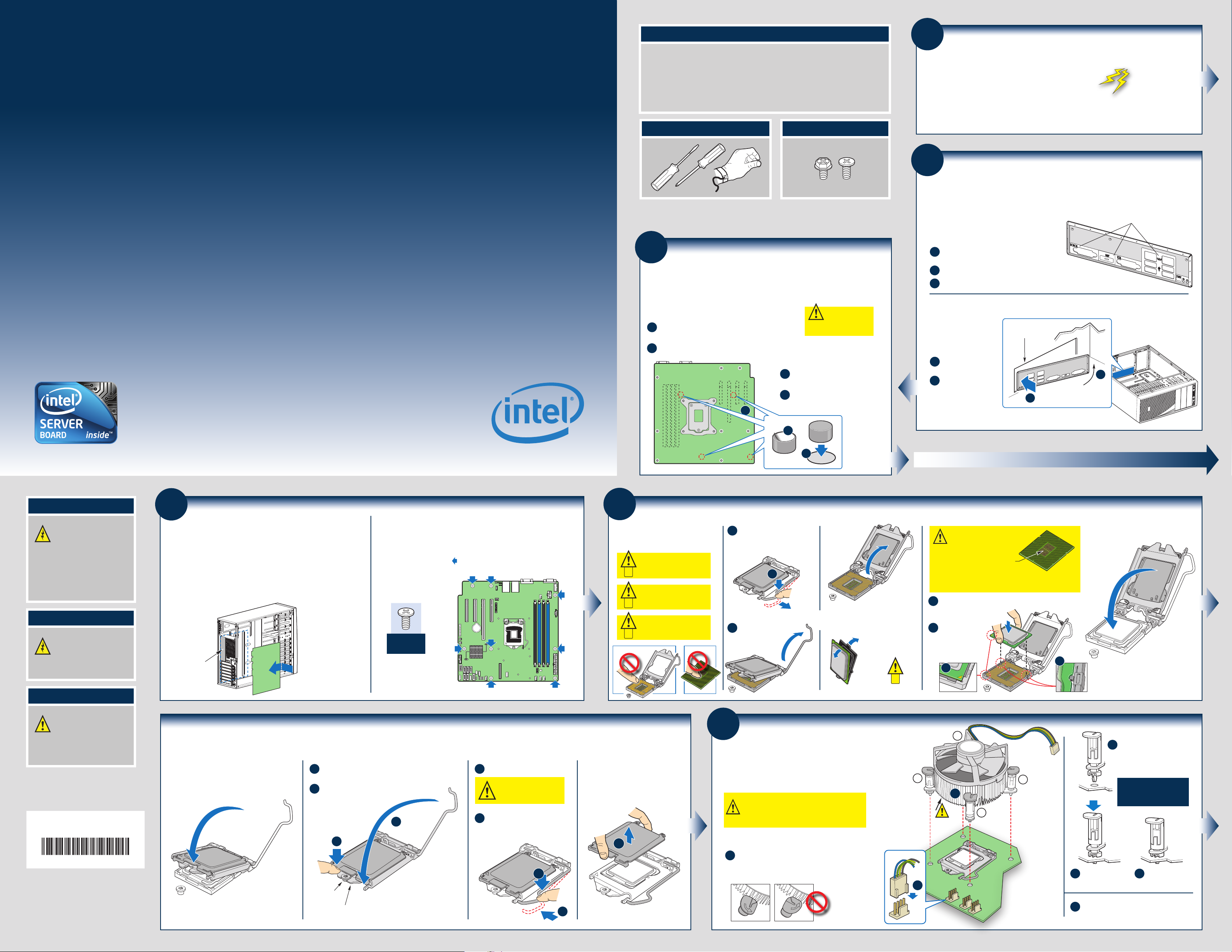
Prepare Server Board
Rotate board to show bottom-side
A
and hold upright as shown.
Locate the four circles as shown.
B
®
Xeon® E3-1200 V3 processors or the 4th Generation Intel® Core™ i3 processors.
Fastener Identification Guide
Phillips*
screwdriver
Anti-static
wrist strap
Install Server Board Bumpers
If you are using a non-Intel® server chassis that includes bumpers, refer to
®
Server Chassis,
B
.
CAUTION:
damage to the server
board, do not lay flat with the
component side down.
Attach the Bumpers
Remove the backing from each
C
bumper.
Press a bumper onto each of
D
the four circles.
®
server chassis
To avoid
1
If using a non-Intel® server chassis, refer to the documentation that came with your chassis for
preparatory steps.
Observe normal ESD (ElectroStatic Discharge) procedures.
Place your Intel® Server Chassis and Intel® Server Board on a
flat anti-static surface to perform the following integration procedures. Always touch the chassis
frame first, before reaching inside to install the server board, make server board connections, or
install other components.
2
Preparing the Chassis
Installing the I/O Shield and Attach I/O Labels
Note: The I/O Shield and label installation procedures shown below apply to the
Intel® Server Chassis P4000S series.
Attach the Labels to the I/O Shield (optional)
Note: Make sure you install the labels on the correct
side of the I/O Shield. Note the orientation of the
cutouts in the drawing before attaching your labels.
Remove the backing from one of the three I/O
A
Shield labels included with your server board.
Press the label onto the I/O Shield as shown.
B
Repeat steps to install the second and third I/O Shield labels.
C
Labels on outside
face of I/O Shield
Install the I/O Shield
Shield is installed from
inside the chassis.
The labels should be visible
from the outside of the
chassis.
Insert one side edge of
A
shield as shown.
Push shield firmly into
B
chassis opening until it
clicks into place.
Chassis Back
Panel Opening
B
A
Intel® Server
Chassis P4000 series shown
Warning
Read all caution and safety
statements in this document
before performing any of the
instructions. Also see the Intel®
Server Board and Server Chassis
Safety Information document at:
http://www.intel.com/support/
motherboards/server/sb/cs-010770
.htm for complete safety information.
Warning
Installation and service of
this product should only be
performed by qualified service
personnel to avoid risk of injury from
electrical shock or energy hazard.
Caution
4
Install the Server Board
IMPORTANT NOTE:
chassis documentation for preparatory steps prior to server board installation.
If you are using a non-Intel® server chassis, see your
A. Insert the Server Board
Place the board into the chassis, making sure that the back panel I/O openings and
chassis standoffs align correctly.
®
• When using the Intel
first, then slide the board back so the I/O connectors fit through the I/O
openings at the rear of the chassis.
I/O Openings
Server Chassis P4000S series, insert the front of the board
Intel® Server Chassis
P4000 series Shown
Front edge
of Board
B. Attach the Server Board
®
The directions below are for the Intel
For a non-Intel
Use screws to attach the board to the chassis at the eight locations indicated by the
solid blue arrows in the figure [ ].
Chassis P4000 series
®
server chassis, use the fasteners that came with your chassis.
Intel® Server
Fastener
Server Chassis P4000S series.
5
Cautions:
A
B
C
Install the
Processor
When removing the protective
cover, DO NOT TOUCH the
gold socket wires.
To avoid damage, DO NOT
DROP the cover onto the
socket wires or components.
When unpacking a processor,
hold by the edges only to avoid
touching the gold contact wires.
C
D
A. Open the Socket Lever
Push the lever handle down
A
and away from the socket to
release it.
A
Rotate the lever
B
open all the way.
B. Open the Load Plate
Open the
load
plate as
shown.
C. Unpack the Processor
Carefully remove
protective cover
as shown.
Save the
protective
cover.
C
D.
Install the Processor
CAUTION: The underside of
the processor has components
that may damage the socket wires if
installed improperly.
Processor must align correctly with
the socket opening before installation.
DO NOT DROP processor into socket!
Orient the processor with the socket so that the processor
A
cutouts match the two
socket pins.
Note the location
B
of the gold key
at the corner of
the processor.
Components
B
Carefully lower the load plate
over the processor.
A
Observe normal ESD
[ElectroStatic Discharge]
procedures during system
integration to avoid possible
damage to server board and/or
other components.
Intel is a registered trademark of Intel Corporation or its
subsidiaries in the United States and other countries.
*Other names and brands may be claimed as the property
of others. Copyright © 2012, Intel Corporation. All rights
reserved.
G83551-002
Install the Processor ...continued
E. Close the Load Plate
Carefully lower the load plate
over the processor.
F. Engage the Load Plate
A
B
Shoulder
Screw
Make sure the front edge of the load plate slides
under the shoulder screw as the lever is lowered.
Close the load plate locking lever.
B
A
Load Plate
Front Edge
G. Latch the Locking Lever
Push down on the locking lever.
A
CAUTION: DO NOT damage the
server board with the tip of the
locking lever.
Slide the tip of the lever under the
B
notch in the load plate. Make sure
the lever is securely latched.
A
H.
Remove the Cover
Carefully lift the cover
straight up as shown.
A
A
6
Save the
protective
cover.
Install Active Heatsink(s)
An active heatsink is required for the Intel® Entry Server Chassis
P4000 series. A typical active heatsink is shown at right.
Rotate the active heatsink so that the power connector can reach
the CPU fan header on the server board.
CAUTION: The heatsink has thermal interface
material (TIM) on the underside of it. Take caution
not to damage the thermal interface material. Use
gloves to avoid injuries from sharp edges.
Use the following procedure to install an active heatsink
to your server board:
Make sure the screwdriver slot at the top
A
of each fastener is rotated perpendicular
to the blades of the heatsink as shown.
2
E
B
TIM
3
Align the heatsink to the holes
B
in the board and lower assembly
Note: Heatsink
styles may vary
1
A
to the board. Snaps go through
holes in server board.
Repeat B-D for each
fastener in the numerical
order shown at left.
4
Press downward
C
on the top of the cap.
Plug the fan cable into the CPU fan header.
E
Fastener snaps
D
into final position.
Page 2
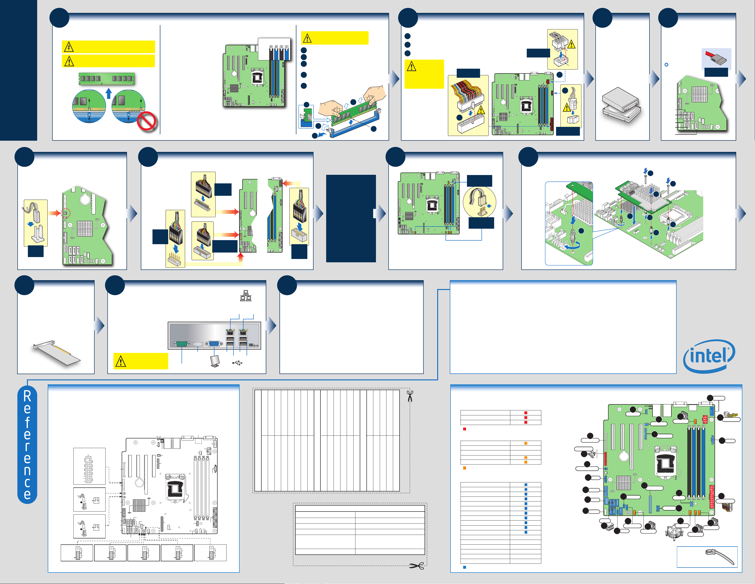
7
Side 2
DIMM
notch and
socket
bump must
align as
shown.
Install DIMM Memory Modules
DDR3L DIMM Memory Identification:
CAUTION: Observe normal ESD (ElectroStatic Discharge) procedures
to avoid possible damage to system components.
This server board supports up to 4 DDR3 1066/1333/1600
ECC UDIMM.
DDR3
Other
Memory
Memory Configurations and Population Order:
DIMM B2 B1A2 A1
Memory Type: Minimum of one
1 GB, DDR3 1066/1333/1600
MHz ECC UDIMM.
Note: For additional memory
configurations, see the Technical Product
Specification on the Intel
Deployment Toolkit DVD that
accompanied your Intel
S1200V3RP Family Products, or go to:
http://www.intel.com/p/en_US/support/se
rver.
Memory sizes and configurations are supported only for DIMMs tested by Intel
For a list of supported memory, see the tested memory list at
http://serverconfigurator.intel.com/sct_app.aspx.
®
Server
®
Server Board
®
.
To Install DIMMs:
CAUTION: Avoid touching contacts when
handling or installing DIMMs.
Open both DIMM socket levers.
A
Note location of alignment notch.
B
Insert DIMM making sure the connector edge
C
of the DIMM aligns correctly with the slot.
Push down firmly on the DIMM until it
D
snaps into place and both levers close.
IMPORTANT! Visually check that each
E
latch is fully closed and correctly
engaged with each DIMM edge slot.
E
C
D
A
8
Make Server Board Power Connections
Attach the P/S Auxiliary power connector.
A
Attach the CPU power connector.
B
Attach the main power connector.
C
CAUTION:
location of the
latch on each power cable
connector and align it with
the matching tab on each
server board socket.
IMPORTANT NOTE:
If you are using a
non-Intel
®
server
Note the
Main Power
Connector Detail
CPU Power
Connector Detail
chassis with an ATX
power supply, see
the documentation
C
that came with your
B
chassis for installation
information.
Latch
Tab
B
A
Auxiliary Signal
Power Detail
9
Install
Optical Drive and
Hard Drive(s)
See the documentation that
came with your server chassis
for drive installation.
10
Connect Hard
Drives/Optical Drive to
Server Board
Connect SATA Data Cables
to server board here.
Begin cable connections
at the SATA 0 location.
SATA 1
SATA 3
SATA 5
SATA 0
SATA 2
SATA 4
SATA Data
Cable Connector
Server
Board
11
Attach Intrusion Switch Cable
Note: For a non-Intel® chassis, see your chassis
documentation for intrusion switch requirements.
Intrusion
Switch
Connector
15
Install Add-in
Card(s)
See the documentation that came with your
server chassis for add-in card installation.
For the Intel® Server Chassis P4000S series,
see the Quick Start User's Guide
accompanying the chassis.
Server
Board
12
Attach Front Panel, Serial, and USB Connections
Note: For a non-Intel®
chassis, see your
chassis documentation
for front panel features
and server board
connection requirements.
Internal
USB
Connector
Detail
16
Finishing Up
Before installing your operating system, you must finish your chassis
installation, make I/O connections and plug in AC power.
CAUTION: See your chassis
documentation for AC power and
grounding requirements.
Display Port
(S1200V3RPM only)
Serial A
Video
Front Panel
Connector
Detail
Front Panel
USB
Internal
USB2.0 or USB3.0
Connector Detail
USB
Network
USB 1
USB 2
NIC1
10/100/
1000 Mb
USB 3
1000 Mb
USB 4
NIC2
10/100/
13
Serial B
Internal
Serial
Connector
Detail
IMPORTANT NOTE:
Return to your Intel® Server
Chassis Quick Start User's
®
Guide, or your non-Intel
chassis documentation to
finish installation and
®
configuration of your Intel
Server Board S1200V3RP
series.
Return to this document to
finish up, including software,
BIOS, drivers, and operating
system installation.
For a non-Intel® server chassis, see the "Making Connections...Quick Reference"
section below, and the documentation accompanying your chassis for specific
chassis fan connection requirements.
17
Software
A. Confirm BIOS Version: Look at the Server/System Management screen in the BIOS
Setup Utility to determine the installed BIOS version. Compare this to the versions at:
http://www.intel.com/p/en_US/support/server.
If new versions are available, update the BIOS on your server. See the Technical Product Specification
on the Intel® Server Deployment Toolkit DVD for update instructions.
B. Configure your RAID Controller:
C. Install your Operating System:
and with the operating system.
D. Install Operating System Drivers: With the operating system running, insert the
Intel® Server Deployment Toolkit DVD. If using a Microsoft Windows* operating system, the Intel
Deployment Assistant will autorun and allow you to select the appropriate drivers to install. On other
operating systems, browse the DVD folders to locate and install the driver files.
• BIOS, Drivers, and Operating System Installation
Use the instructions provided with the RAID controller.
Use the instructions provided with the RAID controller
Chassis Fan Connections
System Fan 1-4
Connector
Detail
CPU Fan
Connector
Detail
Common Problems and Solutions
The system does not boot or show video at power-on stage.
•
Check that the +12V CPU power connector is plugged in. The processors will not have any power without this cable.
•
Only Intel® Xeon® E3-1200 V3 processors or the 4th Generation Intel® Core™ i3 processors with 95W and less Thermal Design Power (TDP) are supported on
this server board. Previous generation Intel® Xeon® processors are not supported.
Beep code 1-5-2-1 in a system means you do not have the supported processor installed.
•
The system generates the memory error beep code and POST diagnostic LED message {0XE0~0XEF} that indicates memory errors in early POST.
•
Remember, all DIMMs must be:
–
®
DDR3L 1066/1333/1600 MHz UDIMM.
–
From the same manufacturer.
–
Installed beginning with DIMM A1.
14
Install the Intel® Integrated RAID Module
See the documentation that came with your SAS or ROC module.
A
For a list of hardware components that have been tested with this system, see:
http://www.intel.com/p/en_US/support/server.
D
D
D
C
B
B
B
Note: The standoff at the position A can be found in the server board box.
This standoff is designed for the S1200V3RP server board only.
Intel® Server Board S1200V3RP Family Products
Note: Not all components, jumpers, and connectors are described in this
diagram. Refer to your Server Board Technical Product Specification on the
®
Intel
Server Deployment Toolkit DVD for additional information.
S1200V3RPM only
VGA
SYS FAN_4
TPM
CPU FAN
Enabled
Default
BIOS
Default
J2K6
3
2
Front Panel Header
(J1C3)
2
Power LED
HDD LED
Power Button
Reset Button
ID Button
Temp Sensor
Chassis Intrusion Header
ID
LED
System
Status
NIC 1
Link/Activity
SM Bus
Chassis Intrusion
NIC 2
Link/Activity
NMI
J1F1
HDD LED Header
J1G2
Clear
Default
BIOS
Recovery
J2K8
Status LED ID LED
SATA Key
IO Module
Front Panel
2
2
LCP
USB 5/6
USB 7
SATA 1
USB 8/9
3
2
Recover
Default
SATA 0
Slot 4 ( PCIe x 4 )
SATA 3
IPMB
SATA 2
Password
Clear
J2K9
Battery
SATA 5
SATA 4
Slot 5 ( PCIe x 8 )
3
2
Slot 6 ( PCI e_x16 )
HSBP_I2C
SATA_SGPIO
SYS FAN_1
Password
Clear
Default
Slot 7 ( PCIe x 1 )
NIC2
USB3
USB4
Diagnostic
LED
RMM4 LITE
RMM4 NIC
Force
Update
J3K2
CPU Socket
SAS Module
eUSB SSD
ME
NIC1
USB1
USB2
3
2
Display
Port
CPU Power
DIMM_A2
DIMM_A1
SYS FAN_2
BMC
Force
Update
J3K6
Serial A
Serial_B
DIMM_B2
DIMM_B1
Main Power
SYS FAN_3
3
2
PS AUX
Enabled
Default
AXXTPME5
Trusted Platform Module
®
Common Accessories and Order Codes
Intel
I/O Shield AS1200V3RPIOS
RMTPB080
Integrated RAID Module
Integrated RAID Module RMS25PB080
®
®
®
SATA Slim-Line DVD AXXSATADVD
Intel
Intel
Available Documents
Document/Tool
Technical Product Specification
Monthly Specification Update
Spares, Parts List, and Configuration Guide
Server Configurator Tool
Software and Drivers
Additional Reference documents available at:
http://www.intel.com/support/motherboards/server
RMS25PB040
RMS25KB040
Integrated RAID Module
Integrated RAID Module
Integrated RAID Module RMS25KB080
®
®
Intel
S1200V3RPL/RPO/RPM Common Accessories and Order Codes
Intel
Intel
AXXRMM4R
AXXRMM4Lite
RMS25CB040
RMS25CB080
RMS25JB040
Integrated RAID Module
Integrated RAID Module
Intel
®
Intel
Integrated RAID Module
®
Intel
Remote Management Module 4
Remote Management Module 4 Lite
®
®
®
Intel
Intel
AXX4P1GBPWLIOM
AXX1FDRIBIOM
AXX2FDRIBIOM
GbE I/O Expansion Module
Intel
Quad Port
Additional Reference documents available at:
FDR InfiniBand* ConnectX-3* Module
http://www.intel.com/p/en_US/support/server.
FDR InfiniBand* ConnectX-3* Module
Integrated RAID Module RMS25JB080
®
S1200VRPO/RPM Common Accessories and Order Codes
Intel
AXX10GBNIAIOM
AXX10GBTWLIOM
10GbE I/O Expansion Module
10GbE I/O Expansion Module
®
®
®
Intel
Intel
Dual Port
Dual Port
Content
In-depth technical information
Technical information and issues update
Supported accessories and spares list
Tested peripherals and operating systems list
Tested memory list
Supported processors list
Up-to-date firmware, driver, and utility information
Making Connections to the Server Board... Quick Reference
Required Connections
A. +12V CPU Power Connector
B. Main Power Connector
C. Front Panel Header
=
Make this connection
CPU/System Fan Connections
D. System Fan 1 Header
E. System Fan 2 Header
F. System Fan 3 Header
G. System Fan 4 Header
H. CPU Fan Header
=
Make this connection
Optional Connections
A complete list of accessories and spares can be found at:
http://www.intel.com/p/en_US/support/server.
(Search for the document Spares and Configuration Guide.)
I. HSBP
J. USB 5-6
K. USB 7
L. USB 8-9
M. Chassis Intrusion Header
N. IPMB
O. SATA SGPIO
P. Internal USB SSD
Q. SAS Module Header
R. Serial B
S. P/S Auxiliary
T. IO Module
U. RMM4 Lite
V. RMM4 NIC
W. TPM
X. SATA Connectors
Y. LCP
=
Make this connection
Intel® Server Chassis
P4000S series
Intel® Server Chassis
P4000S series
Intel® Server Chassis
P4000S series
Z
SATA Key
IO Module
Front Panel
U
RMM4 Lite
V
T
RMM4 NIC
Sys Fan 4
C
T
M
Chassis Intrusion
Chassis Intrusion
LCP
Y
Q
USB 5/6
J
HSBP_I2C
N
I
O
SATA SGPIO
IPMB
L
K
USB 7
USB 8/9
SATA
X
Note: For a non-Intel® Chassis, see your chassis documentation for server board
connection information.
Note: Not all optional connections are shown in this diagram. Refer to your Server Board
Service Guide, and your server chassis documentation for additional connection information.
SAS Module
D
Sys Fan 1
eUSB SSD
G
W
TPM
P
H
CPU Fan
E
Sys Fan 2
IMPORTANT NOTE:
Cables should be
tied for better airflow.
Use cable-ties compulsarily.
R
F
Sys Fan 3
Serial B
A
Main Power
S
B
CPU Power
PS AUX
 Loading...