

Page 1
INTEL® FALCON™ 8+
Unmanned Aircraft System
QUICK START GUIDE
Page 2
QUICK START GUIDE – Rev. 06 July 2017 QUICK START GUIDE – Rev. 06 July 2017
2
GloSSARy
• UAV: Intel® Falcon™ 8+ Unmanned Aerial Vehicle (UAV) –
includes all ying parts
• CTR: Intel® Cockpit Controller – ground control station
• BMS: Intel® Powerpack Battery Management System –
smart battery
• UAS: Intel® Falcon™ 8+ System / Intel® Falcon™ 8+
Unmanned Aircraft System (UAS) – Product including UAV
and all dedicated accessories
• Payload: Camera mount with gimbal and camera
InTEnDED USE
This Product is a UAS that is intended for commercial use only,
such as for visual inspection, mapping and surveying. It is
not intended for any consumer or recreational use.
You must read, understand, and follow all documentation
before using the UAS.
DISClAImER
The features and benets of the UAS depend on its
conguration and may require enabled hardware,
software, or service activation. Technical results may have
been estimated or simulated, using internal analysis, or
architecture simulation, or modeling of Intel Corporation,
or Ascending Technologies GmbH, acquired by Intel
Corporation and merged into Intel Deutschland GmbH, and
provided to you for informational purposes. Any dierences
in your UAS hardware, software or conguration may aect
actual performance.
SAfETy SymbolS USED In ThE QSG
Critical Warning: Indicates important information that
can be ight critical.
General Information: Shows information helpful in
operating and using the UAS.
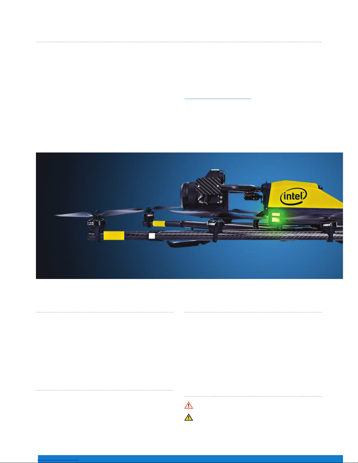
ThAnK yoU foR PURChASInG ThE InTEl® fAlCon™ 8+ UnmAnnED AIRCRAfT SySTEm
Congratulations on your new Intel® Falcon™ 8+ Unmanned
Aircraft System (UAS).
This UAS is purposely built for professional use. It is not
intended for consumer use. You should already have
experience ying a UAS, which requires control of the drone
with a ground control station similar to the one included with
the Intel® Falcon™ 8+ UAS.
This Quick Start Guide (QSG) presents a brief summary of
the UAS, how to set it up and steps to get started. The QSG
consists of the following main sections:
• UAS Description: Packing list, UAS components, ground
control station, payloads, etc.
• Operating the UAS: Safety precautions, pre-ight and
post-ight checks, and steps to get started – preparing,
using and controlling the UAS.
Before using the UAS, please read the Terms and
Conditions of Use, and Safety Warnings enclosed with this
package. It is important that you also read the User Manual
before using the UAS. Download the User Manual at
www.intel.com/Falconmanual .
In addition, Intel strongly recommends that you attend a
pilot training before you use the UAS. For further details
on training, contact the reseller from whom you bought the
UAS, or if you bought the UAS directly from Intel, contact
Intel.
Page 3
3
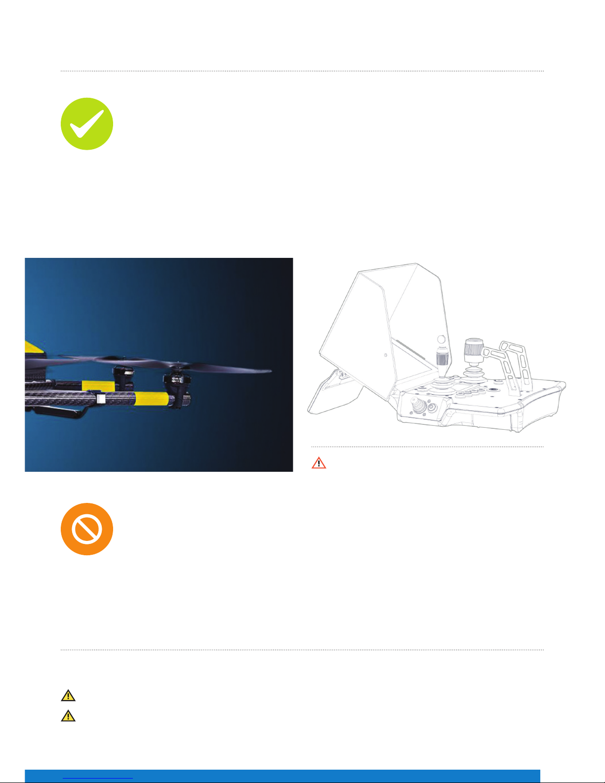
SAfETy GUIDElInES
These guidelines must be read, understood, accepted and followed by any personnel who operate the UAS:
Do’s:
• Comply with all laws and regulations. You are responsible for knowing and complying with all laws and
regulations applicable to the airspace in which you operate.
• Professional drone operators must comply with all applicable insurance, and aviation-specic liability
requirements.
• Conduct the “UAS and safety check”, “pre-ight” and “post-ight” checks according to the User Manual.
• Maintain the UAS in a safe and airworthy condition.
• Use your best judgment, and prioritize the safety of the environment in which you are ying, and the
people and objects within it.
• Fly at a safe distance and/or wear appropriate safety equipment.
• Intensive training of every pilot, to operate the UAS in all ight modes, is mandatory.
• Fly in dry conditions only - the UAS and payloads are not waterproof.
• Operate the UAS only within the specied operational limits.
Don’ts:
• Do not disassemble the UAS.
• Do not transport the UAS in containers not approved by Intel Corporation.
• Do not operate the UAS under the inuence of alcohol or drugs.
• Do not make any unapproved modication to the UAS.
• Do not y beyond the line of sight.
• Do not y in closed or restricted areas.
• Do not y at temperatures below -5° C (23° F) or above +40° C (104° F).
• Do not exceed speed of 16 m/s in Height-Mode or descend faster than 10 m/s in Manual-Mode.
• Do not y in problematic environments with high electromagnetic disturbances.
• Do not operate the UAV in potentially explosive environments.
UAS DESCRIPTIon
What’s Inside the Package?
When you unpack your Intel Falcon 8+ UAS for the rst time, please make sure that all the items, which you specied
in your purchase order, are included.
Make sure the items are not damaged from shipment. If any of the items are missing or damaged, contact your dealer
or contact the technical support team at Intel.
Violation of these safety guidelines might be illegal and
subject to ne, and will result in the loss of warranty.
Page 4
QUICK START GUIDE – Rev. 06 July 2017 QUICK START GUIDE – Rev. 06 July 2017
4
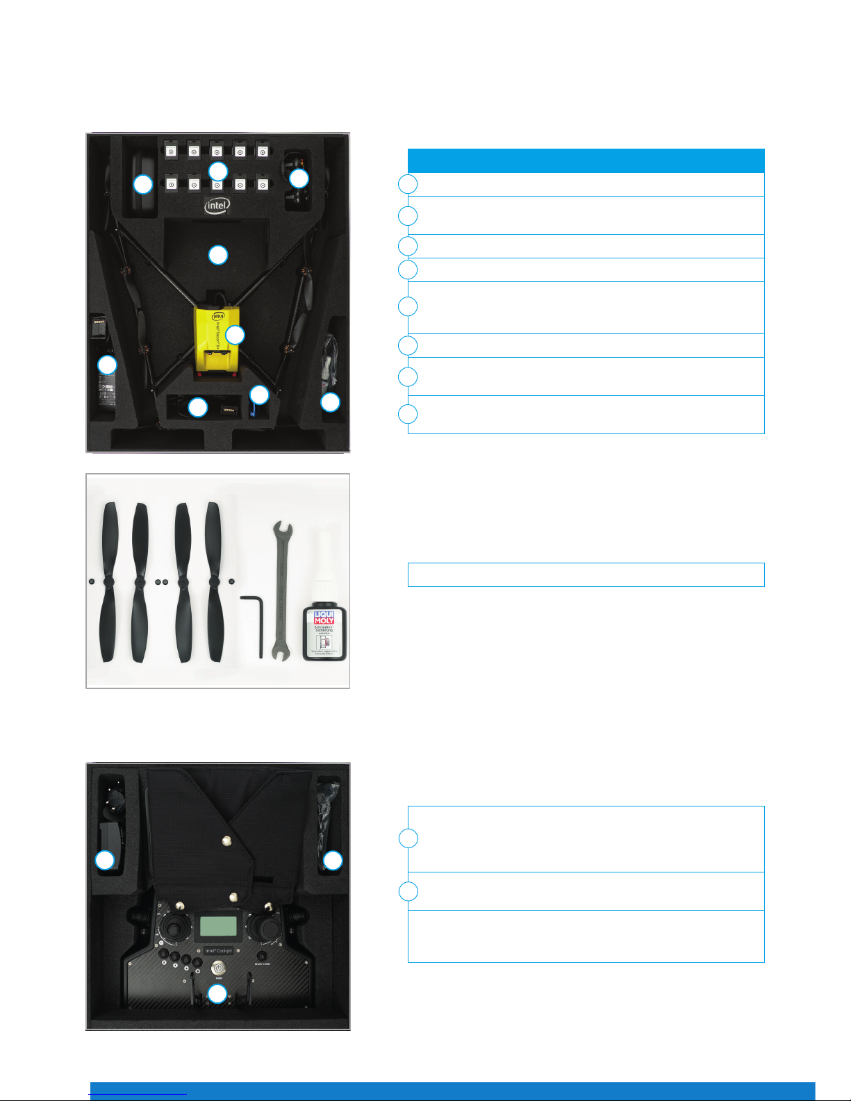
Intel Falcon 8+ UAS Case**
This case is used for all necessary parts of your Intel Falcon 8+ UAS.
Intel Cockpit Controller Case**
Following the numbers, the slots contain:
Intel Falcon 8+ UAV without payload and batteries
Power supply units for charging the Intel Powerpack Batteries
(optional) (6)
Space for accessories, e.g. sun glasses
Toolkit with spare propellers (see Figure 02 below)
Space for the payload when mounted directly onto the UAV.
(For load security you must take the foam bolster inlet, which is
supplied with the payload case.)
Space for Intel Powerpack Batteries (shipped separately)
Space for Independent Camera Control (ICC) gamepad
(optional)
Space for extra equipment, if any, which is not part of the UAS,
e.g. reective safety vest or video goggles
1
2
3
4
5
6
7
8
Figure 01
1
2
2
3
4
5
6
7
8
Toolkit and spare parts
Figure 02
Intel Cockpit Controller with mounted sun shield (for transporting
the Intel Cockpit Controller in the case, the sunshade should be
arranged as shown to provide extra protection of the touchscreen
tablet against scratches during transportation.)
Additional space to store extra items, e.g. an extra power
supply
Included in the case, but not shown:
Shoulder harness, located underneath the sun shield protected
touchscreen tablet.
1
2
1
2
2
Figure 03
Page 5
5
Main Components
The UAS comes with the below main components:
• The Intel Falcon 8+ UAV
• The Intel Cockpit Controller
• The Intel Powerpack Batteries
• Payload
The payload of the Intel Falcon 8+ UAS must be placed as
shown in Figure 04. Make sure that it is placed conveniently
inside the foam bolster.
The foam bolster cover (not shown) located on top of the
payload, should be used to secure the payload when it is
transported in the Intel Falcon 8+ UAS case, while it is mounted
onto the UAV.
** The images of the items above are for illustration purpose only, and the actual item(s) packed with your Intel Falcon 8+ UAS may dier from the one(s) depicted
here dependi ng on, for example, which payload you ordered.
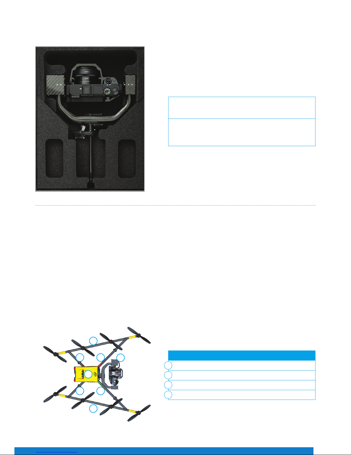
1
2
2
3
4 4
4 4
UAV with payload – top view:
Actively stabilized camera mount with gimbal and camera
Motor rails
Central unit
Carbon cross
1
2
3
4
Payload Case**
The Intel Falcon 8+ UAV
Figure 04
Figure 05
Page 6
QUICK START GUIDE – Rev. 06 July 2017 QUICK START GUIDE – Rev. 06 July 2017
6
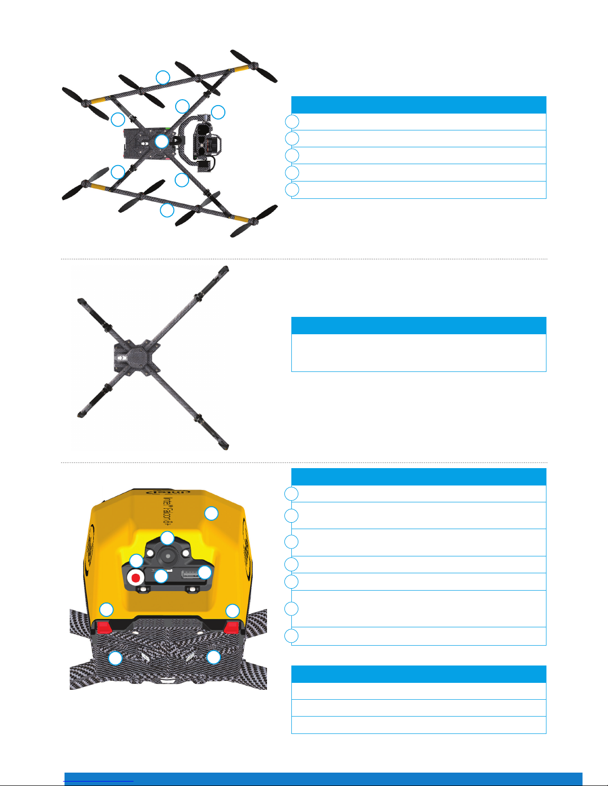
2
2
1
3
5
5
4
4
UAV – back view:
Carbon ber chassis
USB stick slot (supports up to 16 GB, le system: FAT32,
allocation unit size: 32 kilobytes)
Hole for camera mount carbon rod and knurled securing nut
(see no. 5 in Figure 11)
Battery compartments with retaining clips (7) for batteries
Power button
Micro SD-card slot (SD-card: speed class 10 minimum,
supports up to 16 GB, le system: FAT32, allocation unit size:
32 kilobytes); for ight logs (black box)
Battery marks
Built inside:
Electronics for ight stabilization and power supply
Diversity data link modules
Video transmitter module
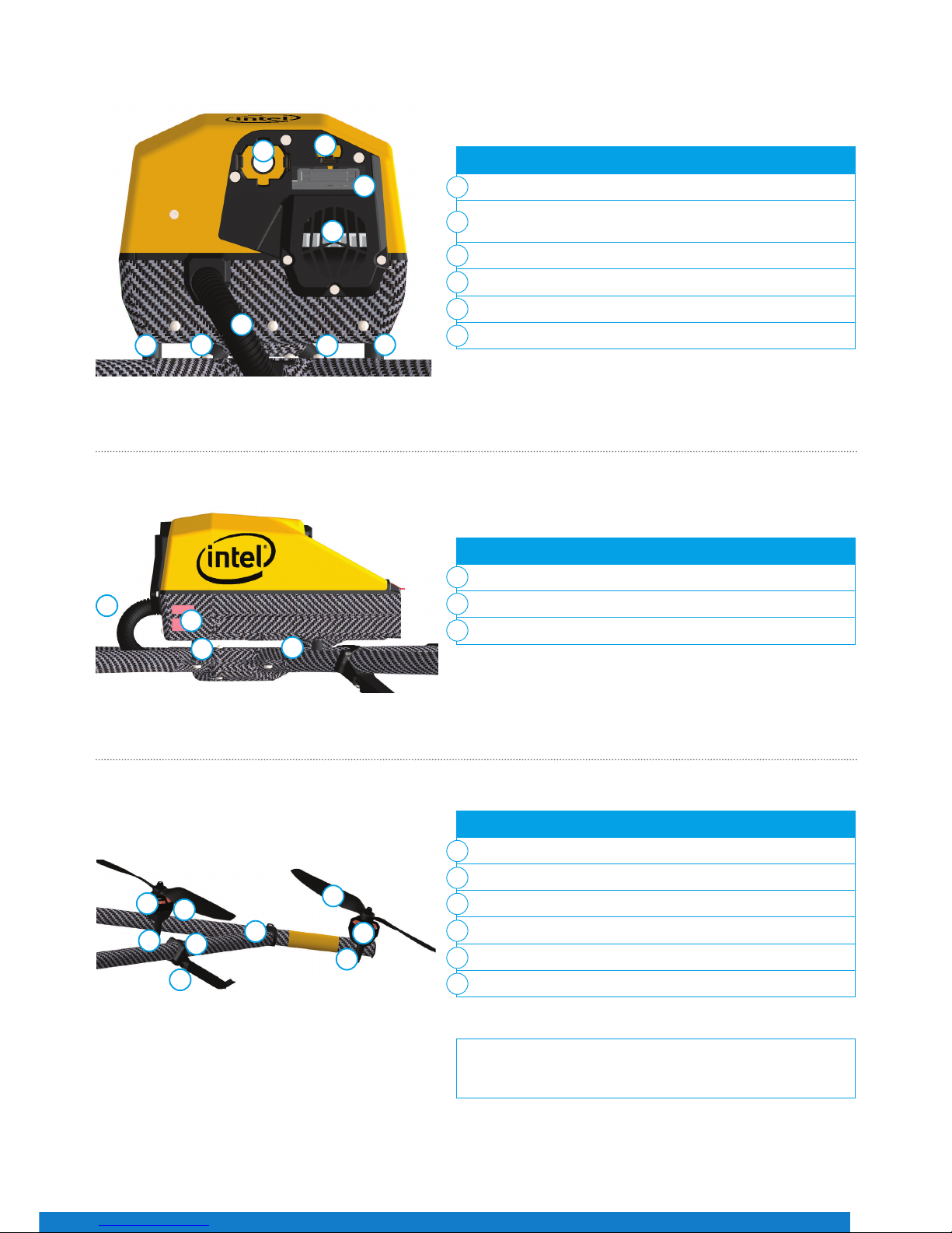
Carbon cross with center cross piece, antenna arrangement:
Data link antennas (2.4 GHz) and video link antennas (5.8
GHz) are integrated into the landing feet. They are diagonally
arranged as shown in Figure 07.
1
2
3
4
UAV with payload – bottom view:
Payload
Motor rails
Center cross piece
Carbon cross
Landing feet
1
2
3
4
5
5
6
7
Figure 07
Figure 08
1
3
5
6
2
7
7
4
4
Video
Video
Data
Data
Figure 06
Page 7
7
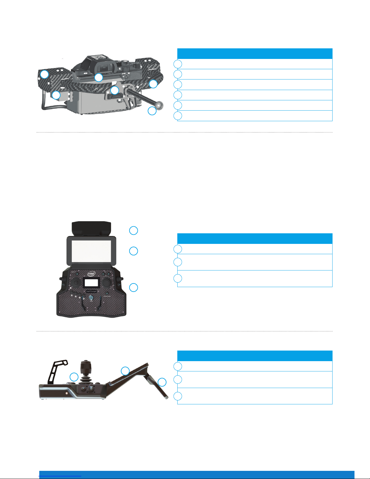
UAV – front view:
Hole for camera mount’s carbon rod
Connector slot for payload adapter plug (see no. 2 in
Figure 25)
Retaining clip for payload adapter
Cable tube containing cabling of antennas (for example)
Fan for internal cooling behind slots
Vibration dampers
Motor rails and related elements consist of:
Propellers (mounted directly on motors)
Brushless motors (mounted directly on mounts)
Brushless motor mount
Carbon ber tube
Connector between carbon cross and motor rails
Landing foot
UAV – side view:
LED position light
Vibration dampers
Cable tube
Each motor rail consists of four brushless motor controllers,
seated within the carbon tube.
1
1
1
2
2
2
3
3
3
4
4
5
5
6
6
Figure 09
Figure 10
1
3
2
5
6
6
4
6
6
3
1
2
2
1
1
2
2
3
3
4
5
6
Figure 11
Page 8
QUICK START GUIDE – Rev. 06 July 2017 QUICK START GUIDE – Rev. 06 July 2017
8
Payload
Overview of the Intel Cockpit Controller
The Intel Cockpit Controller
The payload consists of:
Actively stabilized payload with circuitry for controlling camera
Camera (e. g. Sony Alpha 7R*)
Pitch Servo
Lightweight Carbon Fiber Structure
Knurled Securing Nut for the Camera Mount
Payload Adapter
Controller – top view, with unfolded antenna panel:
Control Unit
Touchscreen Tablet with Preview Video (optional with sun
shield)
Antenna Panel, Unfolded (2.4 GHz data link and 5.8 GHz video
link antennas)
Controller – right side view:
Control Unit
Touchscreen Tablet with Preview Video (optional with sun
shield)
Antenna Panel, Unfolded (2.4 GHz data link and 5.8 GHz video
link antennas)
1
1
1
2
2
2
3
3
3
4
5
6
1
2
3
4
5
6
The Intel Cockpit Controller is the main control hub for the Intel Falcon 8+ UAV, and the attached payloads. It is designed to
be carried and operated by one person, and displays all relevant ight information.
The communication between the Intel Cockpit Controller, and the Intel Falcon 8+ UAV, is realized by two independent 2.4
GHz digital data links. The preview video is transmitted digitally on 5.8 GHz. The Intel Cockpit Controller uses the same
battery type as the Intel Falcon 8+ UAV. The battery is located in the battery compartment, which can be accessed from the
bottom of the Intel Cockpit Controller.
Figure 12
Figure 13
Figure 14
1
2
3
1
2
3
Page 9
9
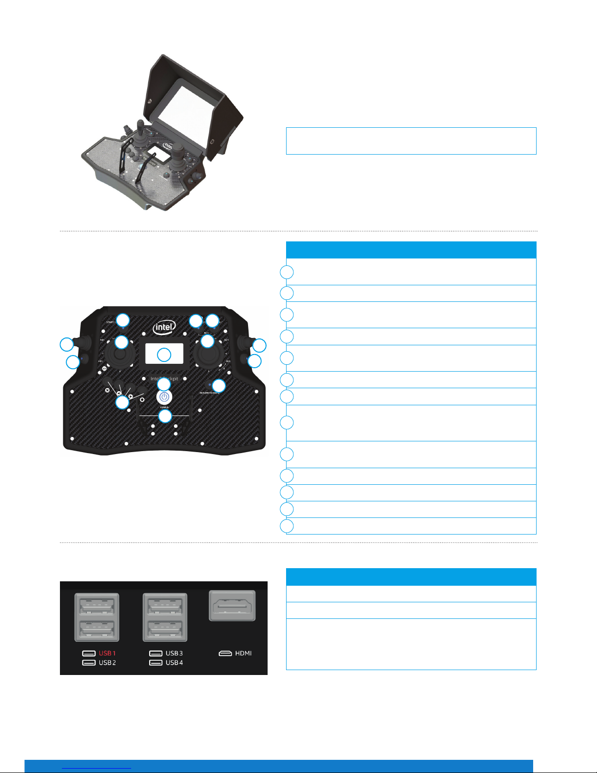
There are dierent connectors on the back of the controller:
4 X USB
1 X HDMI*
The USB port, labeled USB 1, can only be used to perform Intel
Cockpit Controller rmware updates from a USB stick.
The other USB ports can be used to connect the ICC, or USB
sticks with pre-planned ight missions to be imported.
A sun shield can be attached to the touchscreen tablet to avoid
reections. It is foldable for storage and transport.
Figure 15
The functional elements of the controller are:
Start/Stop Button (starts/stops the motors when the left stick
is simultaneously held down at minimum)
GPS (GPS-Mode ON)
HGT (Height-Mode ON) when both buttons are switched ON/lit,
then Manual-Mode is activated
Left Rocker Switch (R1) (controls the camera pitch angle)
Right Rocker Switch (R2) (controls dierent camera functions
depending on the attached payload)
Left and Right Control Sticks
Status Display
Left Push Button (B1) (sets the camera to predened angles
+/-90°, +/-45° and 0° - see "Setting the Camera Angle" section
for details)
Right Push Button (B2) (controls dierent camera functions
depending on the attached payload)
4 Function Buttons for Status Display
Return to Home Button
Power Button
Integrated Shoulder Harness Holders
1
2
3
4
4
5
6
7
7
8
9
10
11
1
2
4
4
5
5
6
7
7
9
10
3
Figure 16
Figure 17
11
8
Page 10

QUICK START GUIDE – Rev. 06 July 2017 QUICK START GUIDE – Rev. 06 July 2017
10
Figure 18
Figure 19
Figure 20
Headphone port (mini-jack): Located on the lower right side of
the Intel Cockpit Controller to connect headphones, which may
be helpful under noisy conditions.
Small loudspeaker: Plays back acoustic warnings inside the
Intel Cockpit Controller when headphones are not connected.
1
2
Battery compartment with magnetic lid: Located on the lower
left of the Intel Cockpit Controller.
Overview of the Status Display
Touchscreen Tablet
The Status Display shows all relevant information for ying. It is built into the Intel Cockpit Controller control unit.
The touchscreen tablet is directly mounted onto the remote unit of the Intel Cockpit Controller, and cannot be removed. It is
powered by the battery of the Intel Cockpit Controller.
The touchscreen tablet serves as a video monitor, displays ight information, and gives access to extended functionality.
Via the Status Display, you can view the current settings, and
adjust specic functions of the UAV. To do so, use the four
buttons under the lower left corner of the Status Display.
Escape (left side) is used to leave menus/submenus, and
to clear functions. In the following text it is displayed as
ESC.
With the Left arrow button (middle, left side) and the
Right arrow button (middle, right side), you can scroll
through menus or alter parameters.
Enter (right side) is used to enter menus and activate
functions. In the following text it is displayed as ENT.
1
1
2
1
Page 11

11
The center of the screen shows the preview video of the mounted payload. All symbols and icons shown here are created
by the camera, and do not have any touch functionality. In the shown example, it is the Sony A7R*. Please refer to the Sony*
camera manual for further information, which can be accessed online:
https://esupport.sony.com/US/p/modelhome.pl?mdl=ILCE7R&LOC=3#/manualsTab
In the status line at the top of this window, general ight information is given.
On the top left corner under “GPS”, the quality of the GPS signal can be seen, indicated by 1 to 5 bars.
Next to the right of the window is the place for UAS messages. If everything is ne, SYSTEM OK is mentioned in a green bar. In
case there are warnings, the eld will turn red and display the respective warning.
Next to the UAS messages is another green bar which indicates the remaining battery capacity as a percentage, followed by
the actual performed ight time and the selected ight mode (GPS).
Tapping the button in the top right corner displays the preview video in full screen mode.
Tapping again will revert to the previous view.
In the lower right corner is more ight information, which refers to the UAV: Orientation, Height, and Distance from the takeo point. Tapping that eld will toggle the view between the video preview and a map view (in case a map has been loaded
from an AscTec Navigator project). Please go to www.intel.com/Falconmanual to learn more about the AscTec Navigator.
In the left top corner (under GPS) are buttons for two dierent functions:
Tapping the PATH button opens the PATH function, where ight paths can be stored and edited.
Tapping the NAVIGATOR button opens the NAVIGATOR window, where AscTec Navigator projects can be loaded
and own.
Tapping this button opens a window which gives information about the software (version, available updates, etc.).
Main Screen
Figure 21
Page 12

QUICK START GUIDE – Rev. 06 July 2017 QUICK START GUIDE – Rev. 06 July 2017
12
Intel Powerpack Battery
The Intel Powerpack Battery powers the Intel Falcon 8+ UAV, and the Intel Cockpit Controller, combining eciency with ease-ofuse. The battery features automatic balancing, storage mode and charging. The intelligent Battery Management System (BMS),
with a One-Button/Five-LEDs user interface, makes everyday battery handling easy.
On the front panel of the battery, there is a sticker. An area is marked by a dot surrounded by a circle. This area has the function
of a button.
One short push (< 2 sec) on the button indicates the charging state of the battery, by showing the respective number of LEDs.
Battery Type Electric Charge
[mAh]
Voltage Standard
[V]
Voltage Fully
Charged [V]
Voltage Lowest
Recommended
(under load) [V]
TNo. of Cells
Intel
Powerpack
Battery
4000 14.8 16.8 14.0 4
The LEDs show the state/phase of charge of the battery.
Status of LED No. 1 2 3 4 5 Charging State
on - - - - 0% - 20%
on on - - - 20% - 40%
on on on - - 40% - 60%
on on on on - 60% - 80%
on on on on on 80% - 100%
The LEDs are integrated in the front panel of the battery.
LED number/color from left to right:
• 1 / Red
• 2 / Yellow
• 3 / Green
• 4 / Green
• 5 / Green
Figure 22
Page 13

13
Charging the Intel Powerpack Batteries
During charging, the current battery state and the progress of the charging are indicated by the LEDs. When the charging process
is nished and the full capacity of the battery is reached, all ve LEDs will keep ashing simultaneously as long as the battery
remains connected to the AC adapter. When charging is nished, just unplug the battery and the AC adapter.
Payloads
Deep camera integration allows the changing of settings from the Intel Cockpit Controller while the UAV is airborne. Cameras
are integrated to remain within their camera mount when the camera is exchanged. Tools are not required to exchange camera
mount. The Intel Falcon 8+ UAS automatically identies the attached camera, and the menus on the Intel Cockpit Controller are
changed accordingly.
To charge the Intel® Powerpack Battery, connect the supplied
charging cable to the Intel® Powerpack Battery and to the
supplied AC adapter. Connect the AC adapter to a wall
socket. Charging will begin immediately.
Figure 23
To install the payload:
1. Feed the camera mount’s carbon rod (without thumbscrew, no.
(4) in Figure 25) into the hole on the front side of the central
unit (1). Make sure it is inserted straight, not at an angle.
2. Ax the payload adapter (Figure 25 below). Take care that
the connector plug of the adapter (no. (2) in Figure 25 below)
ts to the counterpart plug at the front of the UAV (2).
3. Make sure that the ball, of the ball link connector of the roll
servo, is fastened into the respective slot in the adapter (no.
(1) in Figure 25 below) when you ax the camera mount
onto the UAV.
4. Press the releasing clip of the payload adapter (see no. (3) in
Figure 25 below) into the respective counterpart opening (3).
5. Install the thumbscrew nut (no. (4) in Figure 25 below) on the
back side of the central unit (nger tight).
1
2
3
Figure 24
Installing the Payload
1
3
2
The payload adapter is the connection between the camera
mount, and the central unit of the UAV. It is mounted on the
rod of the camera mount, and connected to it by a cable. The
adapter is not xed on the rod, but can be moved within the
length of the cable.
Adapter slot (for the roll servo with ball link connector
inserted)
Connector plug
Releasing clip
Knurled securing nut for the camera mount
Figure 25
1
2
3
4
3
2
1
4
Page 14

QUICK START GUIDE – Rev. 06 July 2017 QUICK START GUIDE – Rev. 06 July 2017
14
The functional elements of the Intel Cockpit Controller are:
B1 (Button1): Sets the camera to predened angles +/-90°,
+/-45° and 0° (see "Setting the Camera Angle" section below for
details)
B2 (Button2): Changes the function depending on the
connected payload, position 1 = LED OFF, position 2 = LED ON
B3 (Button3): Trigger button
R1 (Rocker-Switch1): Camera tilt
R2 (Rocker-Switch 2): Changes the function depending on the
camera used
S2: Turning the right control stick (S2) controls the yaw axis of
the UAV
Status Display: Additional camera options can be accessed
from the Status Display
ESC, LEFT, RIGHT, ENT: Status Display control buttons (left to
right in Figure 26).
1
2
3
4
5
6
7
8
Camera Controls via the Intel Cockpit Controller
Figure 26
Figure 27
4
1
2
5
67
3
Setting the Camera Angle
Sony Alpha 7R*
The main screen of the Status Display shows the camera angle. 0° means the camera is looking straight forward and is levelled
horizontally. -90° means the camera is looking down, 90° means it is looking up.
Push the Rocker-Switch R1 away from you to tilt the camera downwards. Pull the Rocker-Switch R1 towards you to tilt the camera
upwards. The further R1 is pulled, or pushed, the faster is the tilt movement.
When the camera is not at 0°, a single push of button B1 will set it back to 0°. When the camera is at 0°, pushing and holding B1
and simultaneously pushing R1 shortly, will set the camera to -45°; another short push of R1, while holding B1, will set it to -90°.
When pulling R1, while holding B1, the camera can be tilted upwards accordingly in 45° increments.
The Sony Alpha 7R* has two main function dials that can be controlled through the Intel Cockpit Controller:
The default functions of Dial 1 and 2 depend on the selected shooting mode on the camera:
The function of Dial 1 on the Sony A7R can be controlled by R2,
when B2 is in position 1 (LED OFF).
The function of Dial 2 can be controlled by R2, when B2 is in
position 2 (LED ON/Blue) or via the Status Display by pushing
ENT > Camera Options > Dial 2.
The table below shows the default functions of Dial 1 and 2
depending on the selected shooting mode.
Dial 1
Dial 2
B2 Position R2 Function CAMERA SHOOTING MODE
S Mode (Shutter
Priority)
A Mode (Aperture
Priority)
M Mode (Manual)
1 (LED o) Dial 1 Shutter Speed Aperture Aperture
2 (LED on/Blue) Dial 2 Exposure
Compensation
Exposure
Compensation
Shutter Speed
8
Page 15

15
UAS and Safety Check
Inspection Payload ZS50*
The UAS and safety check must be performed once a day before the rst ight, and any time it may be necessary (e.g. after
an incident like a hard landing). If you notice anything unusual, please contact support through your dealer, if you purchased
through a dealer; or support at Intel, if you purchased directly from Intel. You must follow these steps to complete a close UAS
and safety check:
Important settings on both cameras can be controlled via the Intel Cockpit Controller:
To access the camera options, navigate to ‘Camera Option’ on the Status Display:
To access the camera options, navigate to ‘Camera Option’ on the Status Display:
Additional cameras may be available. Please refer to the main manual (http://intel.com/Falconmanual) if your camera is not described here.
B2 Position Activated Camera R2 Function
1 (LED o) Panasonic* RGB
Camera
Zoom In/Out Please note that shooting
parameters like shutter speed,
aperture and ISO need to be set
directly on the camera before
take-o.
2 (LED on/Blue) FLIR Up - Trigger at eld correction
Down - Cycle through color
palette
Please note that preview
parameters like isotherms
and ACG need to be set via
conguration le on the FLIR SD
card before take-o.
Record/Stop Starts and stops a video recording
Dial 2 See previous table for details
Review Reviews images stored on the SD card
Adjust Horizon Adjusts the horizon (roll angle) while ying
Roll Comp. ON/OFF Sets the gimbal to stop compensating roll movements
Switch Camera Switches the live image preview between the two cameras
Adjust Horizon Adjusts the horizon (roll angle) while ying
Roll Comp. ON/OFF Sets the gimbal to stop compensating roll movements
1 Is the transport case free of
visible damage?
If there is new visible damage from the last transport, take special care
during the check of the complete UAS.
2 Is the UAS free of visible
damage?
If there is visible damage, contact your supplier.
3 Are all the propellers in good
condition?
Replace propellers if there are any nicks, cracks, breaks or other damage.
Shooting parameters need to be set directly on the camera before take-o.
oPERATInG ThE UAS
Page 16

QUICK START GUIDE – Rev. 06 July 2017 QUICK START GUIDE – Rev. 06 July 2017
16
4 Are all the propellers rmly
mounted to the connected
motors?
Move each propeller gently while holding the connected motor. The
nut on top of the propellers is self-tightening. It only needs to be
finger tight (20 Ncm +-5 Ncm). Never tighten it with too much force,
as it might damage the motor. To tighten the nut, use the supplied
screw-wrench. Put the screw-wrench on the nut, hold the motor head
with the thumb and index finger of one hand, and use the index finger
of the other hand to turn the screw wrench. As soon as the motor
head starts turning as well, sufficient force has been applied.
5 Nudge every single propeller
so that it turns, and check if
any unusual sound can be
heard, or if a propeller spins
slower than the others and
stops spinning abruptly.
If there is a scratching sound or if a propeller spins slower than the others
without any unusual sound, this might come from an object in the motor.
Please use canned pressurized air to clean the motor. If there is a rattling
sound, this might come from a propeller that is not attached tightly
enough. In this case, carefully check the self-tightening nut on top of the
propeller. Tighten the nut as described in step 4.
6 Is the SD card of the Black
Box (ight logger) correctly
inserted in the back of the
UAV ?
If the Status Display of the Intel® Cockpit Controller (CTR) displays the
message “No user SD” card, please take out the card, make a backup copy,
format it and re-insert it into the UAV.
7 Is the camera mount
correctly attached, and is the
thumbscrew installed in the
back of the UAV?
Make sure that the payload adapter is correctly attached onto the
payload, the camera mount is pushed all the way in, and the thumbscrew
is installed nger tight.
8 Are all the Intel® Powerpack
Batteries fully charged?
Voltage level can easily be checked using the LEDs on the front of the
batteries.
First Steps – Initial Setup
Preparing the Intel Falcon 8+ UAV
When using the Intel Falcon 8+ UAS for the rst time, some additional steps are required, which only need to be performed once.
It may be necessary to repeat them only in rare occasions. In detail, these steps are:
• Visit http://intel.com/FalconDownloads and install the latest rmware on the UAS. Consult the main manual for detailed
instructions on how to perform the rmware update. Regularly check the website for updates.
• Establish the initial connection between Intel Falcon 8+ UAV and Intel Cockpit Controller.
• Set the UAS date and time on the touchscreen tablet of the Intel Cockpit Controller.
• Perform a payload and compass calibration with every payload.
They are clearly indicated in the below descriptions as “First setup only”. All other listed steps are always required when
preparing the Intel Falcon 8+ UAS for ight missions.
1
Slide the batteries with the colored label facing upwards
(1) into the battery compartment. Slide them all the way in
until they are stopped and ush with the end of the slot.
Check that each battery is locked by its retaining clip (2).
The Intel Falcon 8+ UAV must always be own with
two batteries inserted.
Figure 28
2
2
1
Page 17

17
Preparing the Intel Cockpit Controller
2
Switch ON the camera and remove the lens cap. The image
shows the Sony Alpha 7R as an example.
Please note that the ON/OFF switch on each payload is
dierent. For the Sony Alpha 7R, the ON/OFF switch is
located between Dial 1 and Dial 2 in Figure 29.
3
Press the power button (1) for approximately 2 seconds
until you hear a short beep. After approximately 3 seconds,
the LEDs on both sides of the System will be lit, and you will
hear the internal fan running.
The UAV is initialized when the gimbal starts automatically
reacting to the movements of the UAV. It requires
approximately 15 seconds to power ON, and is indicated by
a triple beep from the Intel® Falcon™ 8+ UAV.
Figure 29
Figure 30
1
1
Open the lid of the battery compartment, and slide the
battery with the colored label facing downwards into the
battery compartment. Slide it all the way in until it stops,
and is ush with the end of the slot.
The Intel Powerpack Battery provides power to the Intel
Cockpit Controller, as well as the touchscreen tablet.
2
Install the shoulder harness by connecting the carabiners
of the harness to the rst eyelet of the integrated holder
(circled in Figure 32) on each side of the cockpit.
Figure 31
Figure 32
1
Page 18

QUICK START GUIDE – Rev. 06 July 2017 QUICK START GUIDE – Rev. 06 July 2017
18
3
Switch ON the touchscreen tablet by pushing the power
button (1) on the top edge, right side, for approximately 2
seconds. A short vibration can be felt.
4
Unfold the antenna panel on the backside of the tablet. The
antenna panel must always be pointed at the UAV to ensure
the best possible transmission quality.
Warning: Do not power ON or operate the Intel
Cockpit Controller without fully extending the
antenna panel.
5
Switch ON the Intel Cockpit Controller by pushing and
holding the power button for a few seconds until it vibrates
shortly.
When switching ON the Intel Cockpit Controller,
the center position of the two control sticks is
calibrated. Make sure to not move them while the
Intel Cockpit Controller is powering up. Otherwise
there will be an error message “JOYSTICK ERROR”
and the motors will not start. If this occurs, switch
OFF the Intel Cockpit Controller, and switch it ON
again without touching the control sticks.
6
First setup only.
The rst time the Intel Falcon 8+ UAV and the Intel Cockpit
Controller are powered up, the Status Display will show the
Start Screen, and it is necessary to set up the connection
between UAV and Controller. To do so, follow these steps:
1. Push the ENT button on the Status Display. You will see
the screen to enter the UAS serial number (5-digit serial
number of the Intel Falcon 8+ UAV, printed on the top
side of the UAV above the battery compartment). The
rst digit is highlighted.
Figure 33
Figure 34
Figure 35
Figure 36
1
Page 19

19
First setup only.
2. Push ENT to activate the rst digit.
3. Enter the rst digit of the serial number by using the
arrow RIGHT/LEFT buttons to increase/decrease the
number. (RIGHT increases the number, LEFT decreases
it.)
4. Push ENT to conrm the rst digit. The next digit can be
entered now.
5. Repeat this ve times (for every digit).
6. Push ENT to conrm the serial number. OK is highlighted.
7. Push ENT and the connection will be established.
(The next time the UAS is powered ON, these settings
will be recalled and the connection will be established
automatically.)
7
The rst time the touchscreen tablet is started, it is
necessary to set the UAS time and time zone. To do so, tap,
hold and drag the respective value. When set, conrm with
APPLY SETTINGS.
If SKIP SETTINGS is selected, there will be a warning that
projects might have incorrect data, and time values. At the
next start, the time and date settings will be presented
again.
(Once the settings are applied, the time and date settings
screen will only be shown again after a software update of
the touchscreen tablet.)
8
The touchscreen tablet always starts with the Pre-ight
Checklist, where the most important safety aspects are
listed. Make sure to comply with all aspects shown, conrm
all three check boxes and tap OK before take-o.
You may tap SKIP at your own responsibility. After tapping
OK or SKIP, the main screen of the application is opened.
Figure 37
Figure 38
Payload and Compass Calibration
First setup only.
The rst time that a payload is connected with the Intel Falcon 8+ UAV, it is necessary to rst perform a payload calibration, and
then the compass calibration (strictly in that order). The Intel Falcon™ 8+ UAS will save the calibrations with that exact payload,
and remember it the next time it is used.
If the calibrations are not done, the UAS will use default parameters which will lead to decreased heading accuracies.
Figure 39
Page 20

QUICK START GUIDE – Rev. 06 July 2017 QUICK START GUIDE – Rev. 06 July 2017
20
PAYLOAD CALIBRATION
(Can be done indoors with motors switched OFF)
COMPASS CALIBRATION
(To be done outdoors, inight)
1. Attach the payload to be calibrated.
2. Switch ON the payload, the Intel Falcon 8+ UAV and the Intel Cockpit Controller.
3. In the Status Display, navigate to ‘Settings’ > ‘Payload
Calib.’ and press ‘ENT’.
3. Hover the Intel Falcon 8+ UAV in GPS-Mode around
30 m altitude in a spot with good GPS reception, and no
magnetic disturbances.
4. The camera will rotate fully downwards and then move to
the fully upwards position.
Place the Intel Falcon 8+ UAV on an elevated
platform to make sure the payload does not
hit the ground and cause damage when it tilts
downwards.
4. In the Status Display, navigate to ‘Settings’ > ‘Compass
Calib.’ and press ‘ENT’.
5. When the payload stops moving, switch OFF the payload,
the Intel Falcon 8+ UAV, and Intel Cockpit Controller.
5. After the Intel Falcon 8+ UAV makes a 400° turn, land, and
switch the complete UAS OFF.
6. Restart the complete UAS.
7. Repeat the above steps for every payload to be used.
If, during start-up, a discrepancy is detected between the current magnetic eld and the
expected magnetic eld, the Status Display will show and sound a warning.
If this warning occurs, never take o from that spot in GPS-Mode! It might
lead to unexpected positional changes in the UAV.
Magnetic Field Warning
Figure 40
To resolve the warning, follow these steps:
1. Either switch OFF the complete UAS, choose a dierent starting position, switch the complete UAS ON again in the order
described above, and check if the magnetic eld warning is not shown again. In many situations the disturbances are limited
to small areas.
Page 21

21
1. Switch to Height-Mode, and take-o in Height-Mode to avoid any position corrections by the UAV, which might occur
unexpectedly in GPS-Mode.
2. Fly to open space and keep Height-Mode activated for at least 20 seconds (it will help the estimation algorithms to do some
movements forward, backward, left and right).
3. Switch to GPS-Mode in open space. The magnetic disturbance will then be at a safe distance, and the estimation algorithms
will be active.
4. Always be prepared to switch back to Height-Mode anytime.
(OR)
Link Loss Procedure
When the UAS has successfully initialized, an appropriate Link Loss Procedure must be selected each time the UAS is switched
ON.
In case the connection between the Intel Cockpit Controller and the Intel Falcon 8+ UAV gets lost, the Link Loss Procedure is
activated. The following three Link Loss Procedures are available:
ComeHome Straight: The UAV will stop at its current position, y back to the home
position at its current height, if it is higher than 20 meters (m) above the take-o height;
if it is lower than 20 m, it will ascend to approximately 20 m above the take-o height
and then y back to the home position. When the UAV reaches the spot above the home
position, it will descend at 1.5 m/s until it lands.
ComeHome High: The UAV will stop at its current position and ascend. After arriving
at the maximum altitude that was reached during the ight, it will y back to the home
position, and descend at 1.5 m/s until it lands.
Use with caution: If the battery is low at the end of a ight, the extra power
needed to ascend could deplete the battery, and lead to a critical situation.
Direct Landing: The UAV will stop and start a controlled descent at 1.5 m/s at its current
position, until it lands. If no GPS is available, the UAS will always use Direct Landing.
Please note that in a situation without GPS signal, the UAV will drift with the wind while
descending.
Figure 41
Figure 42
Figure 43
In case the Link Loss Procedure has been activated, it is recommended not to use Manual-Mode. Using GPS or
Height-Mode, will make it easier for the pilot to react correctly, when the data link is re-established and the
Link Loss Procedure is interrupted, because the UAV will automatically control the height.
It is possible to dene a new home position while the UAV is in the air. To do so, enter the menu on the Status
Display and go to ‘Navigation’ > ‘New Home Position’.
Figure 44 Figure 45
Page 22

QUICK START GUIDE – Rev. 06 July 2017 QUICK START GUIDE – Rev. 06 July 2017
22
Flight Modes
GPS-Mode
The Intel Falcon 8+ UAS can be operated in three ight modes:
• GPS-Mode
• Height-Mode
• Manual-Mode
• When there is no input from the pilot, the UAV will:
o Keep its orientation in the air
o Maintain its position within the limits of the GPS accuracy (approximately 2-5 m)
o Keep its height within the limits of the height controller (approximately 1-3 m)
o Compensate for wind speed up to 12 m/s
• The inputs via the Intel Cockpit Controller control the speed of the UAV directly.
o Roll and pitch angles are limited to 45°
o Speed in horizontal plane is limited to 4.5 m/s
o Ascent rate is limited to 3 m/s
o Descent rate is limited to 3 m/s
See below an overview of controlled parameters depending on the ight mode:
The ight modes can be selected with the two switches on the upper right of the Intel Cockpit Controller.
Flying in GPS-Mode is easiest, as it provides the highest level of automation.
When the UAS is switched ON, GPS-Mode will be activated by default. If there is no sucient GPS reception,
Height-Mode will be activated automatically, and the Height-Mode button will be lit. In this case, the GPS-Mode
button will ash, to indicate that the UAS will switch to GPS-Mode as soon as there is a valid GPS signal. In
such a situation, it is recommended to actively switch to Height-Mode by pushing the respective button, before
taking o. This way, any unexpected switch of the ight mode can be avoided.
• When the button GPS is pushed and is lit, GPS-Mode is active
• When the button HGT is pushed and is lit, Height-Mode is active
• When both buttons are pushed simultaneously and both are lit, Manual-Mode is active
Figure 46
Mode GPS Button HGT Button Altitude Control Height Control Position Control
GPS-Mode ON (lit) OFF √ √ √
Height-Mode OFF ON (lit) √ √ -
Manual-Mode ON (lit) ON (lit) √ - -
Page 23

23
Height-Mode
Starting and Stopping the Motors
Manual-Mode
• When there is no input from the pilot, the UAV will only:
o Keep its orientation in the air
o Keep its height within the limits of the height controller (approximately 1-3m)
• The UAV will neither keep its position nor compensate for wind
• The position must be held manually by the pilot
• The inputs via the Intel Cockpit Controller control the roll and pitch angles of the UAV
o Roll and pitch angles are limited to 50°
o The direction and speed of the UAV are inuenced by the wind direction and speed
o Ascent rate is limited to 3 m/s
o Descent rate is limited to 3 m/s
• When there is no input from the pilot, the UAV will only:
o Keep its orientation in the air
• The UAV will not keep its position and height, nor will it compensate for wind
• Controlling the position and height has to be done manually by the pilot from the Intel Cockpit Controller
• The inputs via the Intel Cockpit Controller control the roll and pitch angles and the thrust of the UAV
o Roll and pitch angles are limited to 50°
o The direction and speed of the UAV are inuenced by the wind direction and speed
The Manual-Mode is for experts only.
Avoid full throttle inputs in Height-Mode! The UAV can be overstressed in certain situations, e.g. ying abrupt
maneuvers with a low battery.
When the GPS quality is insucient, Height-Mode will automatically be activated. Shortly before this point,
positional accuracy might already be too low and it is strongly recommended to actively switch to Height-Mode
in situations with insucient GPS quality.
If the UAS automatically switches from GPS-Mode to Height-Mode, the GPS-Mode button will be ashing, while
the Height-Mode button will be lit permanently. This indicates that the UAS will switch back to GPS-Mode
automatically when a valid GPS signal is received.
If the UAV seems to be unstable or has diculties in keeping its current position in GPS-Mode, immediately
activate Height-Mode. Be prepared to control the position manually on the Intel Cockpit Controller.
• Keep the left control stick down
• Push up the Start/Stop switch for at least one second
• Follow the same procedure to switch OFF the motors again
As a safety measure, the motors will be switched OFF again, if the left control stick is
not kept in the fully downwards position while the motors are starting. Therefore, do
not move the left control stick, and keep it down while the motors are starting.
While the Intel Falcon 8+ UAV is on the ground with the motors running, always keep
the left control stick in the fully downward position to avoid an unintentional takeo.
Figure 47
Page 24

QUICK START GUIDE – Rev. 06 July 2017 QUICK START GUIDE – Rev. 06 July 2017
24
Pre-Flight Check
Ensure all the below factors are in place before the ight:
1. Is the UAS in proper condition (according to the points listed in the ‘UAS and Safety Check’ section)?
2. Make sure to have an empty and correctly formatted SD card inserted in the camera.
3. Are there two batteries fully inserted in the Intel Falcon 8+ UAV, with the colored label facing upwards?
4. Is the battery of the Intel Cockpit Controller fully inserted, with the colored label facing downwards?
5. Is the Intel Cockpit Controller in proper condition (no loose parts), and is the antenna panel folded out?
6.
Place the UAV on the take-o location and verify the following:
• There is enough space to take-o and land (no people, animals or obstacles within a radius of 10 m).
• There are no obstacles around that could shadow the GPS signal.
• The surface allows all propellers to spin freely.
• There are no small rocks, dust or sand which could be sucked into the motors.
• There are no magnetic elds to be expected.
To avoid interferences with the UAS, set your smartphone to airplane (ight) mode.
Always switch ON the UAS in the following order:
1. Payload
2. Intel Falcon 8+ UAV
3. Touchscreen tablet
4. Intel Cockpit Controller
Now wait for the link to be established.
7.
The end of the boot process is marked by a triple beep emitted by the Intel Falcon 8+ UAV. During booting,
the Intel Falcon 8+ UAV does not need to stand still. It can be moved - for example, it can be started from a
moving boat.
8.
The start-up process is nished when camera mount stabilization starts working (can be heard with a gentle
buzzing sound from the gimbal).
9.
Make sure to comply with all points in the checklist presented on the touchscreen tablet. If so, conrm the
checklist. Is the preview video image visible on the touchscreen tablet?
10.
Choose a Link Loss Procedure which is suitable, for the current ight mission.
11.
Is the displayed remaining battery capacity of the Intel Cockpit Controller sucient for the planned mission
(displayed in minutes in the Status Display – see chapter “In Flight”)?
12.
Is the remaining battery capacity of the Intel Falcon 8+ UAV at least 80% (displayed in the top line of the
touchscreen tablet)?
Page 25

25
Taking O
13. Does the bottom line of the Status Display show OK?
14. Is the GPS quality ≥ 4 bars? This is mandatory, if you want to y in GPS-Mode.
15. Is the wind speed within the operational limits 16 m/s in Height-Mode or 12 m/s in GPS-Mode?
16. Choose the correct ight mode (usually GPS-Mode or Height-Mode).
Switch the motors ON (with both hands).
While the Intel Falcon 8+ UAV is on the ground with running motors, always keep the left control stick in the fully downward position.
17. Are all of the motors running correctly?
18. Ready for take-o!
Violation of these safety precautions may result in the loss of warranty included in the Terms and Conditions
of Sale for this Product.
GPS-Mode Height-Mode Manual-Mode
1. Make sure to have sucient GPS
reception. If the GPS signal quality is
sucient, push the GPS button on the
Intel Cockpit Controller. It will light up.
1. Push the HGT button on the Intel
Cockpit Controller. It will light up.
1. Push the GPS and HGT buttons
on the Intel Cockpit Controller
simultaneously. They will both light up.
2. Start the motors.
3. Center the right control stick and push the left control stick completely up to
ascend.
3. Center the right control stick, and
push the left control stick almost
completely up. The vehicle will lift-o
very quickly. Be prepared to reduce
thrust quickly after a safety distance
to the ground is reached. The actual
safety distance depends on the
specic circumstances of the takeo spot (wind, distance to obstacles,
etc.).
4. Once at a safe height, bring back the
left control stick to the center.
4. Once in the air, use the right control
stick to compensate for the wind.
4. Once in the air, control all the axes
manually.
In Manual-Mode, the UAV will automatically descend when there is not enough thrust. Give at least
approximately 50% thrust to maintain height (depending on the attached payload).
Page 26

QUICK START GUIDE – Rev. 06 July 2017 QUICK START GUIDE – Rev. 06 July 2017
26
Flight
Basic Flight Principles - There are four controllable
directions:
• Roll Axis: Movement to the left or right
• Pitch Axis: Movement forward or backward
• Yaw Axis: Adjust the heading of the UAV
• Thrust: Ascend or descend along the yaw axis
Figure 48
Controlling the Intel Falcon 8+ UAV from the Intel Cockpit Controller
The control mode is called Mode 2. In this mode:
Roll
Pitch
Yaw
The left control stick controls
Thrust and Yaw
The right control stick controls
Pitch, Roll and Yaw
Thrust: Up = Ascend, Down =
Descend
Pitch: Up = Fly forward, Down = Fly
backward
Yaw: Left = Turn heading left, Right =
Turn heading right
Roll: Left = Fly left, Right = Fly right
Figure 49
Figure 51
Figure 50
Figure 52
The upper part of the right control stick can be turned, which controls the yaw movement
of the UAV. This special function makes controlling the UAV very intuitive, as all controls to
move the UAV in the horizontal pane are accessible with a single hand.
Figure 53
Note that all directional indications are always referring to the point of view of the UAV. Depending on where
the UAV is heading, directions may be dierent from the point of view of the pilot.
Page 27

27
In Flight
Battery Warnings
Landing
During the ight, relevant telemetry information can be viewed on the Status Display’s Main Screen, which is illustrated below:
There are several acoustic and visual warnings (visible at the bottom of the Status Display) which alert you to low battery charge,
or empty battery:
• First warning: ‘Battery weak, land soon’ and a vibration of the Intel Cockpit Controller. The audio warning is repeated
every 20 seconds.
→ The battery voltage is ~<= 14.4 V or the remaining maximum ight time is under 4 minutes.
• Second warning: ‘Battery empty, land now’ and a vibration of the Intel Cockpit Controller.
→ The battery voltage is ~<=14.1 V or the remaining maximum ight time is under 2 minutes.
The UAV must be landed immediately after this warning. When there is only one minute of remaining ight time
left, the Intel Cockpit Controller will vibrate every 10 seconds.
The UAV must be landed by the pilot! There is no auto-landing in case of low or empty battery.
1. Intel Falcon 8+ UAV remaining battery voltage
2. Intel Cockpit Controller remaining battery capacity
3. Active ight mode
4. GPS quality
5. Camera tilt angle
6. Current height and ight time
7. Status line (OK or potential warnings)
8. Trigger counter
Figure 54
GPS-Mode Height-Mode Manual-Mode
1. Adjust the camera to a horizontal position.
2. Fly the UAV to your desired landing area at a safe height of at least 3 m.
3. Descend slowly to 1.5 m height and wait for the UAV to stabilize.
4. Center the right control stick, while moving the left control
stick about half way down to bring the UAV down.
4. Use the right control stick to compensate for horizontal
movements, and carefully move the left control stick down
to bring the UAV down.
5. Right before touchdown – at 0.2 to 0.3 m – move the left control stick down gradually until the UAV lands on the ground.
6. Stop the motors.
1 2 3
4
5
6
7
8
Page 28

QUICK START GUIDE – Rev. 06 July 2017
28
Switching OFF the UAS
Always switch the UAS OFF in the following order:
1. Payload (wait at least 10 seconds until it has stored all data, and is fully powered down);
2. Intel Falcon 8+ UAV:
a. Push and hold the power button
b. The LED position lights will increase in brightness
c. The LED position light will decrease in brightness, and simultaneously there will be a short beep from the UAV
d. After the beep, let go of the button
3. Intel Cockpit Controller:
a. Push and hold the power button of the touchscreen tablet for approximately 3 seconds until “Slide to shut
down your PC” is shown. Follow this instruction to fully power down the touchscreen tablet.
b. Push and hold the power button
c. The Intel Cockpit Controller will vibrate shortly
d. Let go of the button
Post-Flight Check
Ensure the below factors are in place:
• Camera: Adjusted to horizontal position before landing
• All batteries: Removed
• Antenna panel on Intel Cockpit Controller: Folded in
• UAS Storage: In the transport case or backpack
• Intel Cockpit Controller: Shoulder harness removed
Violation of these safety precautions may result in the loss of warranty included in the Terms and Conditions
of Sale for this Product!
fIRmwARE & DESKToP SofTwARE
Check for new rmware and desktop software updates on a regular basis. Download the latest rmware update and desktop
software for your Intel Falcon 8+ UAS at:
www.intel.com/FalconDownloads
Intellectual Property Rights: All texts, images, and graphics published in this document are exemplary illustrations and protected by copyright. Reproduction or the
use of these texts, images and graphics in other digital or printed publications are not permitted without the express permission of the author.
AscTec, Ascending Technologies, and the Ascending Technologies logo are trademarks of Intel Corporation in Germany and/or other countries.
Intel, the Intel logo, and Falcon are trademarks of Intel Corporation in the U.S. and/or other countries.
Other names and brands may be claimed as the property of others.
This publication is protected by copyright. No part of the publication may be used, reproduced, or translated, in any form, without the prior written consent of Intel
Corporation.
© 2017 Intel Corporation. All rights reserved.
 Loading...