

Page 1

Intel® Express 9545 Router
Quick Start
Page 2

Copyright © 2000, Intel® Corporation. All rights reserved.
Intel Corporation, 5200 NE Elam Young Parkway, Hillsboro OR 97124-6497
Intel Corporation assumes no responsibility for errors or omissions in this manual. Nor does Intel make any commitment to
update the information contained herein.
* Other product and corporate names may be trademarks of other companies and are used only for explanation and
to the owners benefit, without intent to infringe.
First Edition April 2000 A22130-001
Page 3

Contents
Quick Start
1
2
3
4
Configuration Worksheets ................................. 6
LED Indicators .................................................10
Install the Router Hardware ....................2
Install Intel® Device View ....................... 3
Install the Router in Intel Device View ... 4
Configure the Router ............................. 5
Local Management ..........................................12
Viewing Online Manuals...................................13
Regulatory Information ....................................14
1
Page 4
w
Quick Start
Install the Router
1
Hardware
Important! Before you install the router,
read the warnings on page 14.
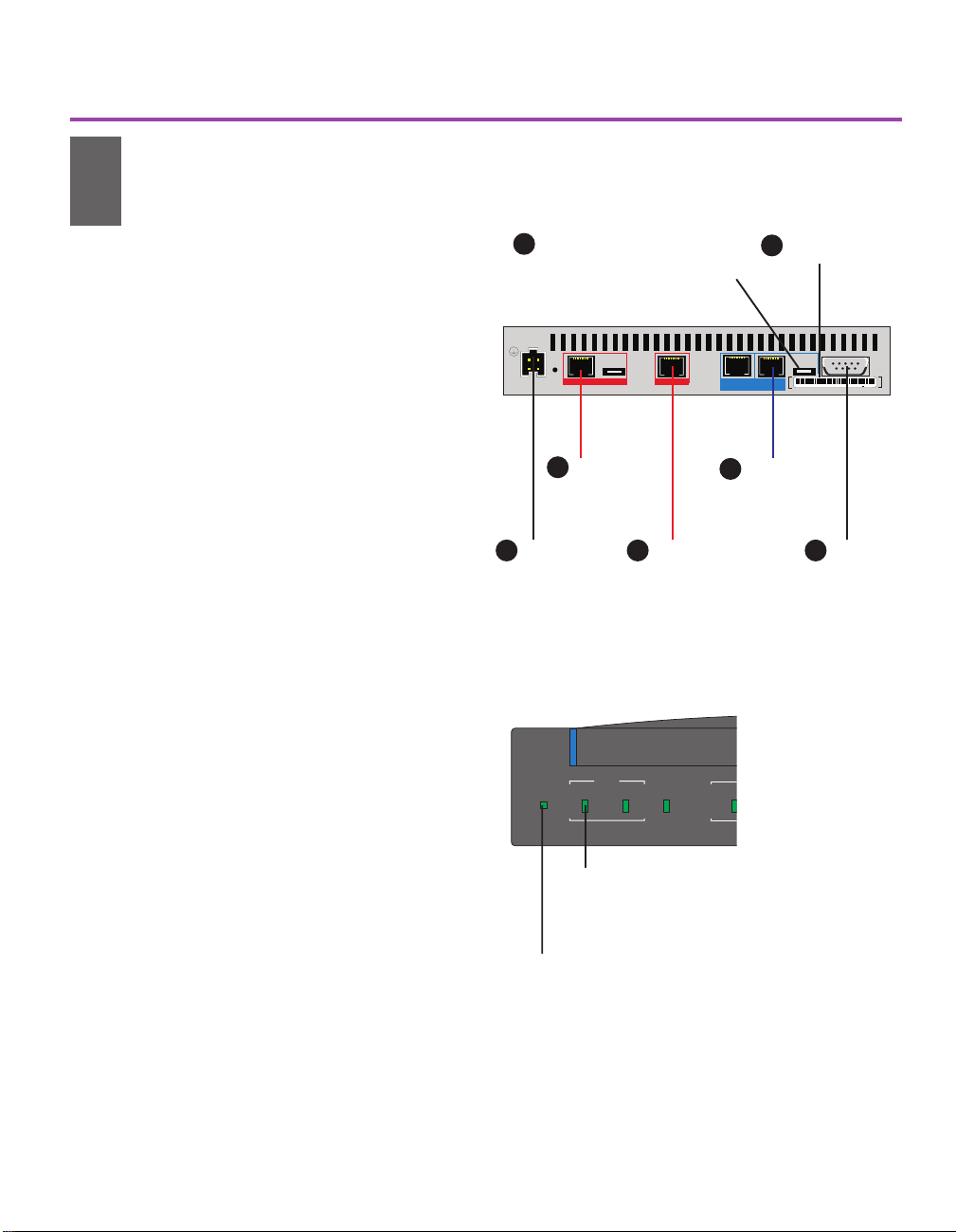
1 Write down the MAC address from the
label near the LAN port, for use during
setup.
Connect to your LAN
2a Connect the LAN1 port to the local
network or the Ethernet port of a PC,
using the provided blue cable.
2b Set the HUB/PC switch to Hub|| when
connecting to a network hub or Ethernet
switch, and PC X when connecting to a
PC.
Connect to your WAN Services
3a Connect the HDSL2 port to your HDSL2
line using one of the provided red cables.
This port provides HDSL2 access to a T1
service and supports Frame Relay, X.25,
or a PPP leased line.
3b Connect the ISDN port to the ISDN or
IDSL service using one of the provided
red cables.
For an ISDN S/T-interface port, you
normally do not change the 100W/Norm
switch setting. Norm is the default
setting and works for most installations.
See the user guide for details about this
switch.
3c If you are using the Console port for a
dial-up connection via a modem, connect
the port to a modem using the cable
provided with your modem (not the
terminal cable supplied with the router).
Connect the Power
4 Connect the router to a power source
(100-250 V AC) using the provided
power supply and cord.
Set switch:
2b
Hub II for hub or switch
Write down
1
MAC address
PC X for single computer
Input
5.1VDC/2.6A
Power
Connect
4
to power
source
Recovery
3b
100Ω Norm
ISDN S/T
red
Connect
to ISDN
or IDSL
HDSL2
red
Connect to
3a
HDSL2 line
LAN 2
10 Mbps
2a
LAN 1
10 / 100 Mbps
blue
Connect
to LAN
HubIIPC
MAC
ADDRESS
00AA00D1865D
Console
X
Connect
3c
to dial-up
modem
(optional)
CASE
123456
ASSY
user
789
supplied
Figure 1. Connecting the Express 9545 Router. See
the user guide for details on connecting the LAN2 port.
Intel Express 9545 Router
®
Status LAN LAN 2 Net
LAN 1
100 Mbps
LAN LED
Green - port is operational and ready for
configuration.
Orange - port is down. Check cables.
Status LED
Green blinking - router is in factory default and ready
for configuration.
Red - error, router is not operational.
Figure 2. Check Status and LAN LEDs. See page 10 of
this guide for a complete description of LEDs.
4007
2
Page 5
Quick Start
Install Intel® Device
2
View
Intel® Device Windows* 95, 98, or 2000
View (Windows) Windows NT* 4.0
Intel Device View manages and configures
the router from a PC running Microsoft
Windows*, or through a Web browser. We
recommend using Intel Device View;
however, the Local Management section in
this guide describes alternate management
methods.
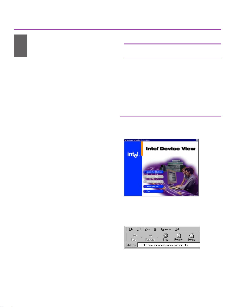
1 Insert the Intel Device View CD-ROM
in your computers CD-ROM drive.
The Intel Device View installation screen
appears. If the screen does not appear
within 10 seconds, run the autoplay.exe
file on the CD-ROM.
2 Select the version of Intel Device View
you want to install.
Click Install for Windows to use
Intel Device View on only the PC
where you install the software.
Click Install for Web to install Intel
Device View on a PC with a Web
server. You can then access Intel
Device View from any PC on your
network using a supported browser
(see Figure 4). Table 1 lists the system
requirements.
Click Install as Plug-in to install Intel
network device support for HP
OpenView*, Tivoli NetView*, or Intel
LANDesk® Network Manager.
Intel Device Browser Internet Explorer*
View (Web) 4.0 or later
Web Server Windows NT* 4.0 (server or
workstation) with Internet
Information Server (IIS) * 3.0
or later, Peer Web Services
3.0 or later, Netscape
Enterprise Web Server* 3.51
Client OS Windows NT Server 4.0 or
Windows NT Workstation 4.0,
Windows 95, 98, or 2000
Table 1. Intel Device View System Requirements.
Figure 3. Intel Device View Installation. Choose
the version, then follow the screen instructions in
the installation wizard.
3 Follow the screen instructions to
complete the installation.
Select Launch Intel Device View on the
final installation screen, then continue
with the instructions on the next page of
this guide.
Figure 4. Access Intel Device View for Web from
any PC on the network. Start Internet Explorer
and type the following in the Address field:
http://
servername
where
servername
your Intel Device View Web server.
/deviceview/main.htm
is the IP address or name of
3
Page 6

Quick Start
Install the Router in
3
Intel Device View
The Device Install Wizard sets up the router
for management in Intel Device View by
performing basic configuration, such as
assigning an IP address.
1 If it is not already running, start the
Device Install Wizard by selecting Install
from the Device menu (see Figure 5).
2 Click Next.
3 When the routers MAC address appears
(see Figure 6), select it and click Next.
The MAC address is on the label near the
LAN port on the back of the router.
Note The MAC address appears only for
routers with a factory default IP
address (as indicated by the Status
LED blinking green). If the router
has already been assigned an IP
address, select Manage from the
Device menu and enter the routers
IP address. You can also reset the
router to the factory default settings
(see the instructions below).
4 Assign the routers IP address (see Figure
7), then follow the Device Install Wizard
screen instructions. The routers default
IP address is 192.0.2.1. We recommend
that you do not use the default address as
your routers IP address.
Figure 5. Start the Device Install Wizard. Select
Install from the Device menu to start the Wizard.
Figure 6. Select the MAC Address. If the router’s
MAC address does not appear, check the LAN
connection and verify that the router is set to factory
defaults, as shown by a blinking green Status LED.
5 On the Device Install Wizard - Finish
screen, select Configure the device,
then follow the screen instructions.
To reset the router to factory defaults:
1 Press the Recovery button located on the back of the
router. After a few seconds the Status LED blinks orange.
2 Press and hold the Recovery button until the LEDs begin to
blink in sequence. When the Status LED blinks green, the
router is set to factory default.
4
Figure 7. Assign an IP address. Type the IP
address and subnet mask for the router.
Page 7

Quick Start
Configure the Router
4
Intel Device View supports the Connection
Setup program for configuring the router.
Wizards guide you through setting up the
ports, then adding connections to the ports.
Configuration Tips
Your service subscription (the informa-
tion you get from your service provider)
should provide most of the information
required to complete the configuration.
You must configure a port before you can
add a connection to it.
To Configure the Router
1 Complete the Configuration Worksheets
on pages 6-9.
Figure 8. Connection Setup Program.
- double click to set up a port
- double click to add a connection
2 Select Connection Setup from the
Configuration menu of Intel Device
View.
3 Set up the port to which you want to add
a connection.
Double-click the port icon or select
the port and click Set Up Port (see
Figure 8).
Follow the screen instructions.
4 Add remote connections to the port.
Double-click the Add Connection
icon under the port, or select the
port and click Add Connection.
Select the appropriate connection
scenario for your network (see Figure
10), and follow the screen instructions.
Figure 9. Port Setup. Complete the wizard using
the information from your service provider (such as
an ISP).
Figure 10. Add Connection. Select the connection
scenario for your installation. Click help for more
details on each choice.
5
Page 8

Configuration Worksheet
These pages help you gather needed information before using a Connection Setup wizard. The
information you’ll need varies depending on the router model, your type of service, and the type of
connection you want to establish. Consult your telephone company, ISP, and system administrator
to determine which parts of this worksheet you should fill in.
Get information from your telephone company for your type of connection
For ISDN
ISDN Switch Type (check one)
Europe
m Euro ISDN / ETSI
Japan
m KDD m NTT
North America
m National ISDN-1 m National ISDN-2 m AT&T 5ESS m Nortel DMS-100
Australia
m Austel TS013 m Euro ISDN / ETSI
ISDN Numbers and SPIDs for your router
Local ISDN Number 1: _____________________ SPID1: _________________
Local ISDN Number 2: ___________________ SPID 2:_________________
Note:
You might have one, two, or no SPIDs depending on your ISDN service type.
ISDN Connection Type
m Single Channel (56 or 64 kbps)
m Multiple Channels (112 or 128 kbps)
m Always On/Dynamic ISDN (AO/DI)
Local X.25 Address: _________________
Remote X.25 Address: _______________
TEI (Terminal Endpoint Identifier): ________________
For IDSL (ISDN Digital Subscriber Line)
General for all connection types
Service type
m PPP leased line m Frame Relay
Line Speed (kbps)
m 64 m 128 m 144 (ISDN U ports only)
For Frame Relay connections only
LMI Type (DLCMI)
m Annex D m Annex A m LMI (Cisco) m None
Connection Name
Local DLCI (
6
(define your own)
between 16 and 991): _______
: ___________________
Page 9

Configuration Worksheet
Get information from your telephone company for your type of connection
For HDSL2
General for all connection types
Framing format
m ESF m D4
Terminal unit
m remote end m central end
Line Speed: _______kbps
Channel Usage
m Continuous m Custom m Alternate (Odd) m Alternate (Even)
For Frame Relay connections only
LMI Type (DLCMI)
m Annex D m Annex A m LMI (Cisco) m None
Connection Name: _________________________
Local DLCI (
For X.25 connections only
Packet Size:
m 128 m 256 m 512 m 1024
Window Size
between 16 and 991): _____________
(between 1 and 7): ______
m Only use PVCs (Permanent Virtual Circuits)
m Use PVCs and SVCs (Switched Virtual Circuits)
Lowest two-way channel: _____
Highest two-way channel: _____
q Enable Flow Control
Connection Name
Connection Type
m PVC (Permanent Virtual Circuit)
Logical Channel Number: _____
m SVC (Switched Virtual Circuit)
Local X.25 Address: _________________
Remote X.25 Address: _______________
(define your own)
: _________________________
7
Page 10

Configuration Worksheet
Get this information from your network system administrator
General for all connection types
LAN IP Address of router
IP address: ___________________ Subnet mask: ___________________
Select one, both, or none for your network:
m Enable firewall filtering (you’ll need to set up filters to allow certain traffic, such as Web,
FTP, and Telnet, to pass over the network.)
m Enable router management from the Internet
For a direct connection to a remote site
ISDN numbers for remote site
Remote ISDN number: _________________ Remote ISDN number 2: _________________
Authentication for access to this router from the remote site (the router at the other end)
Remote user ID: _____________________ Remote user password:___________________
Authentication for access to the remote site router from this router
Your user ID: _________________________ Your password: _______________________
Routing Protocols (choose one or more)
m IP m IPX m Bridging (for non-routing protocols)
IP Routing Type
m RIP-1 m RIP-2 m Static Route m Default Route
q Triggered RIP-1/RIP-2
If it is a static route, enter this information for the remote network:
Network Address: _____________________ Subnet Mask: ___________________
q Enable router management over this connection
Bridging
m Transparent m Spanning Tree
IPX Routing on the WAN
q IPX WAN negotiation
Routing Update Interval:
m Minutes: _____ m 1 hour m 24 hours
8
(if using bridging)
(if using IP)
(if using IPX)
Page 11

Configuration Worksheet
Get this information from your Internet Service Provider (ISP)
Remote ISDN Number (only if you are using ISDN to connect to your ISP)
Remote ISDN number: ___________________
This is the ISDN number of your service provider
IP address assigned to you by the ISP
m No IP address (it is dynamically assigned by the ISP each time the router makes a
connection)
m Single IP address: ___________________
m Multiple IP addresses
If you are using multiple IP addresses, choose one:
m Use your LAN IP address directly on the Internet as a public address.
m Enter a different network IP address for the router:
Network IP address: ________________
Subnet mask: _____________________
Your WAN connection IP address is:
m Unnumbered (most common)
m Numbered
If numbered, enter the following:
IP address: _________________
Subnet mask: _______________
.
9
Page 12

LED Indicators
This section lists the meanings of the LEDs on the Intel Express 9545 router.
Intel Express 9545 Router
®
Status LAN LAN 2 Network Channel 2 Line Status Network Connection
LAN 1
ISDN
Channel 1100 Mbps
HDSL2
LED Color Meaning
Status
Status Green, steady Router is operational.
Green, blinking Router is set to factory defaults and is ready for configuration.
Orange, steady Diagnostic error; router is operational.
Orange, blinking Router is in Recovery Mode.
Red, steady Fatal error; router is not operational.
LAN
LAN (2) Green, steady Port is operational; no data activity.
Green, blinking Data activity on the LAN.
Orange, steady Port is either down or disabled.
Orange, blinking Ethernet collisions on the port.
100 Mbps Green, steady Ethernet LAN is operating at 100 Mbps.
Off Ethernet LAN is operating at 10 Mbps.
ISDN
Network Green, steady Connection to ISDN switch is established.
Orange, steady No connection to the ISDN switch; ISDN port is disabled.
Orange, blinking slow Attempting to connect to the ISDN switch.
(1 time per second)
Orange, blinking fast Maintenance testing (ISDN/U interface only)
(5 times per second)
Red, steady Error, cannot establish connection to the ISDN switch.
4005
10
Page 13

LED Indicators
LED Color Meaning
Channel 1 Green, steady ISDN B-channel established, no data activity.
Green, blinking Data activity on the ISDN B-channel.
Orange, steady No call connected, ISDN B-channel not established.
Orange, blinking Trying to connect call and establish the ISDN B-channel.
Red, steady Error establishing the ISDN B-channel
Channel 2 Green, steady ISDN B-channel established, no data activity.
Green, blinking Data activity on the ISDN B-channel.
Orange, steady No call connected, ISDN B-channel not established.
Orange, blinking Trying to connect call and establish the ISDN B-channel.
Red, steady Error establishing the ISDN B-channel.
HDSL2
Line Status Green, steady Successful connection to the HDSL2/CSU of the data network
switch.
Orange, steady Attempting to establish connection to the HDSL2/CSU on the
data network switch. Corresponds to a HDSL2/CSU Yellow Alarm.
Orange, blinking Testing the line.
Red, steady Error, unable to transmit data to the HDSL2/CSU on the data
network switch. Corresponds to CSU Red, Blue and out-of-frame
alarms.
Network Green, steady Connection to the data network switch is established.
Orange, steady No connection to the data network switch, HDSL2 port is
disabled, or not configured.
Orange, blinking Attempting to connect to the data network switch.
Red, steady Error connecting to the data network switch.
Connection Green, steady WAN connection established; no data activity on the port.
Green, blinking Data activity on the port.
Orange, steady No call connected; WAN connection not established.
Orange, blinking Attempting to establish a WAN connection.
Red, steady Error establishing WAN connection.
All LEDs
All LEDs blinking in a sequence Router is loading firmware.
11
Page 14

Local Management (optional)
Local Management is an on-board, menu-based
management interface that supports full monitoring
and configuration capabilities. You can use Local
Management as an alternative to Intel Device View.
For more details on using Local Management, see the
user guide.
To Access Local Management through the
Console Port
Use the supplied terminal cable to connect the
router console port to a VT100-compatible
terminal or the serial port of a PC running terminal
emulation software (such as HyperTerminal*). See
Table 2 for the correct serial port settings.
Press E
to display the Local Management
Login screen (see Figure 12).
Select Administrator and press
E
twice to
display the main screen. By default, no password is
assigned.
Note If the console port is currently configured
for a dial-up modem, you cannot use it for
Local Management until configuring the port
for a terminal connection. See the user guide
for details.
VT100 terminal
or PC with terminal
emulation software
Router
Figure 11. Connect to the Console Port.
Parameter Setting
Baud 9600
Data bits 8
Parity None
Stop bits 1
Flow Control None
Table 2. Serial Port Settings.
3032
To Access Local Management Remotely
using Telnet
Telnet to the IP address of the router from a
terminal on the LAN, or over a WAN connection
to the router.
The routers default IP address is 192.0.2.1 with a
subnet mask of 255.255.255.0. A terminal on the
LAN must have the same network number as the
router. For example, in Figure 13, the terminal on
the same LAN as the router has an IP address of
192.0.2.2.
12
Figure 12. Local Management Login Screen. Use the
W Z keys on your keyboard to select an option and
press
E
, or type the underlined letter of the option.
Terminal
Express Router
being configured
( default IP address 192.0.2.1)
Input
5.1VDC/2.6A
Recovery
HDSL2
LAN 2
10 Mbps
LAN
ISDN U
Power
Console
HubIIPC
X
LAN 1
CASE
MAC
123456
789
00AA00D1865D
ASSY
ADDRESS
10 / 100 Mbps
Configured with IP
address: 192.0.2.2
sub mask: 255.255.255.0
TELNET
192.0.2.1
Figure 13. Telnet to Local Management. A terminal on
the LAN must be on the same subnet as the router.
3033
Page 15

Viewing Online Manuals
You can view and download user manuals and product documentation from the Intel Device View CD-ROM
and from the Intel Support Web site. To view the manuals, your PC must have Adobe Acrobat* Reader
version 3.0 or higher. The Intel Device View CD-ROM contains a copy of Acrobat* Reader version 4.05 and
Internet Explorer* 5.01 that you can install.
Manuals on the Intel Device View CD
The following manuals are located in the Manuals directory.
Manual Title File name
Intel Express 951x, 952x,and 9545 Routers 951x_952x_9545 Router User Guide.pdf
User Guide
Intel Express Router - Reference Manual ER_Ref.pdf
Intel Express 9545 Router - 9545 Router Quick Start.pdf
Quick Start (this guide)
Table 3. Online manuals available on the Intel Device View CD-ROM
Documentation on the Intel Support Web site
For the latest version of user manuals and other product literature, see the Intel Support Web site at:
http://support.intel.com
Search for the Express 9545 router and look for a link to manuals and literature. If you do not have an
appropriate Web browser, see the instructions below for installing Internet Explorer version 5.01.
To Install Acrobat Reader
1 Insert the Intel Device View CD-ROM in your computers CD-ROM drive.
2 From the Intel Device View installation screen, click Install Add-ons.
3 Select Acrobat Reader 4.05 and click Ok. Follow the on-screen instructions to complete the installation.
To Install Internet Explorer
1 Insert the Intel Device View CD-ROM in your computers CD-ROM drive.
2 From the Intel Device View installation screen, click Install Add-ons.
3 Select Internet Explorer v5.01 and click Ok. Follow the on-screen instructions to complete the installa-
tion.
13
Page 16

Regulatory Information
Statutory Notices & Warnings
Important!
The Intel Express Router must be installed by authorized technical personnel. It must be handled with great care at all times, and must
not be exposed to violent shock or any other influences that may result in damage and possible functionality failures. Intel cannot be
held responsible for any damage arising as a result of incorrect handling or installation.
EMC caution
This is a Class A product. In a domestic environment this product may cause radio interference, in which case the user may be required
to take adequate measures.
Use of shielded cables
To comply with EMC and FCC emission limits, use the shielded cables recommended by Intel Corporation. Use unshielded cables only
where explicitly allowed in the installation manual of the product in question.
Power supply wiring color code
The wires in the power supply cable provided with this equipment are color coded as follows:
FCC Statements
FCC part 15 warning
This equipment has been tested and found to comply with the limits for a Class A digital device, pursuant to part 15 of the FCC Rules.
These limits are designed to provide reasonable protection against harmful interference when the equipment is operating in a
commercial environment. This equipment generates, uses and can radiate radio frequency energy and if not installed and used in
accordance with the instruction manual, may cause harmful interference to radio communications. Operation of this equipment in a
residential area is likely to cause harmful interference in which case the user will be required to correct the interference at his own
expense.
FCC part 68 notice
This equipment complies with Part 68 of the FCC rules. Located on the equipment is a label that contains, among other information, the
FCC registration number. If requested, this information must be provided to the telephone company.
This equipment cannot be used on the telephone company-provided coin service. Connection to Party Line Service is subject to State
Tariffs.
If this equipment causes harm to the telephone network, the telephone company will notify you in advance that temporary
discontinuance of service may be required. If advance notice isnt practical, the telephone company will notify the customer as soon as
possible. Also, you will be advised of your right to file a complaint with the FCC if you believe it is necessary.
The telephone company may make changes in its facilities, equipment, operations and procedures that could affect the operation of the
equipment. If this happens, the telephone company will provide advance notice in order for you to make the necessary modifications in
order to maintain uninterrupted service.
If trouble is experienced with this equipment, please contact:
Intel CorporationJones Farm
2111 N.E. 25th Avenue
Hillsboro, Oregon 97124-5916
Telephone 503-696-8080
If the trouble is causing harm to the telephone network, the telephone company may request you to remove the equipment from the
network until the problem is resolved.
It is recommended that the customer install an AC surge arrester in the AC outlet to which this device is connected. This is to avoid
damaging the equipment caused by local lightening strikes and other electrical surges.
Color Connection
Green and yellow Ground (Earth)
Blue Neutral
Brown Live
14
Page 17

Regulatory Information
This equipment uses the following USOC jacks and codes:
Interface Facility Interface Code Service Order Code Jack Type
ISDN BRI ST 02IS5 6.0N NA
ISDN BRI ST 02IS5 6.0N RJ49C
Industry Canada Notice
IC CS-03 NOTICE (Canada)
The Industry Canada label identifies certified equipment. This certification means that the equipment meets certain
telecommunications network protective, operational and safety requirements as prescribed in the appropriate
Terminal Equipment Technical Requirements document(s). The department does not guarantee the equipment will
operate to the users satisfaction.
Before installing this equipment, users should ensure that it is permissible to be connected to the facilities of the
local telecommunications company. The equipment must also be installed using an acceptable method of
connection. The customer should be aware that compliance with the above conditions may not prevent degradation
of service in some situations.
Repairs to certified equipment should be coordinated by a representative designated by the supplier. Any repairs or
alterations made by the user to this equipment, or electrical malfunctions, may give the telecommunications
company cause to request the user to disconnect the equipment.
Users should ensure for their own protection that the electrical ground connections of the power utility, telephone
lines and internal metallic water pipe system, if present, are connected together. This precaution may be
particularly important in rural areas.
Caution
Users should not attempt to make such electrical connections themselves, but should contact the appropriate
electrical inspection authority, or electrician, as appropriate.
The standard connecting arrangements (telephone jack type) for this equipment are CA-A11 and CB-1D.
Approvals
The Express Router complies with the following requirements:
Safety UL 1950
CSA-C22.2 No. 950
IEC950
EN 60950
Telecommunications FCC part 68
IC CS-03
Emission FCC part 15 Class A,
EN 55022 Class A
CISPR 22 Class A
Susceptibility EN 55024
CISPR 24
CE Mark No
15
Page 18

16
 Loading...