

Page 1

Intel Express 8100 Router
Reference Manual
Page 2

Second edition April 1998
Copyright © 1998, Intel Corporation. All rights reserved.
Intel Corporation, 5200 NE Elam Young Parkway, Hillsboro, OR 97124-6497
Intel Corporation assumes no responsibility for errors or omissions in this manual. Nor does Intel make any commitment to update the information contained herein.
* Other product and corporate names may be trademarks of other companies and are used only for explanation and to the owners’ benefit,
without intent to infringe.
ii
Page 3

Contents
Part I LAN and WAN Links and Services
1 LAN and WAN Services in the Router . . . . . . . . . . . . . . . . . . . . . . . . . . . . . 1
LAN Services . . . . . . . . . . . . . . . . . . . . . . . . . . . . . . . . . . . . . . . . . . . . . . . . . 1
WAN Services . . . . . . . . . . . . . . . . . . . . . . . . . . . . . . . . . . . . . . . . . . . . . . . . . 2
WAN Services and Protocols Available . . . . . . . . . . . . . . . . . . . . . . . . . . 3
General Facilities for WAN Services . . . . . . . . . . . . . . . . . . . . . . . . . . . . . 3
2 Leased Lines Links . . . . . . . . . . . . . . . . . . . . . . . . . . . . . . . . . . . . . . . . . . . . 8
Point-to-Point Protocol (PPP) . . . . . . . . . . . . . . . . . . . . . . . . . . . . . . . . . . . . . 8
Data Compression . . . . . . . . . . . . . . . . . . . . . . . . . . . . . . . . . . . . . . . . . . 11
Data Encryption . . . . . . . . . . . . . . . . . . . . . . . . . . . . . . . . . . . . . . . . . . . . 11
Peer Authentication using the Challenge Handshake Authentication
Protocol (CHAP) . . . . . . . . . . . . . . . . . . . . . . . . . . . . . . . . . . . . . . . . . . . 12
Peer Authentication using the Password Authentication Protocol (PAP) 15
3 Frame Relay Services . . . . . . . . . . . . . . . . . . . . . . . . . . . . . . . . . . . . . . . . . 17
4 ISDN Services . . . . . . . . . . . . . . . . . . . . . . . . . . . . . . . . . . . . . . . . . . . . . . . . 20
Integrated Services Digital Network (ISDN) in the Intel Express 8100
Router . . . . . . . . . . . . . . . . . . . . . . . . . . . . . . . . . . . . . . . . . . . . . . . . . . . . . . 20
ISDN Concept . . . . . . . . . . . . . . . . . . . . . . . . . . . . . . . . . . . . . . . . . . . . . . . . 21
ISDN Services . . . . . . . . . . . . . . . . . . . . . . . . . . . . . . . . . . . . . . . . . . . . . . . . 22
ISDN Numbering and Addressing . . . . . . . . . . . . . . . . . . . . . . . . . . . . . . . . . 24
BRA and PRA Numbering . . . . . . . . . . . . . . . . . . . . . . . . . . . . . . . . . . . . 26
MSN (Multiple Subscriber Number) . . . . . . . . . . . . . . . . . . . . . . . . . . . . 27
SUB (Sub-addressing) . . . . . . . . . . . . . . . . . . . . . . . . . . . . . . . . . . . . . . . 27
DDI (Direct Dialing In) . . . . . . . . . . . . . . . . . . . . . . . . . . . . . . . . . . . . . . 27
Permanent ISDN . . . . . . . . . . . . . . . . . . . . . . . . . . . . . . . . . . . . . . . . . . . . . . 28
ISDN Standards . . . . . . . . . . . . . . . . . . . . . . . . . . . . . . . . . . . . . . . . . . . . . . . 28
ISDN Network Interface Reference Configurations . . . . . . . . . . . . . . . . . . . 30
5 X.25 Services . . . . . . . . . . . . . . . . . . . . . . . . . . . . . . . . . . . . . . . . . . . . . . . . 32
X.25 Characteristics . . . . . . . . . . . . . . . . . . . . . . . . . . . . . . . . . . . . . . . . . . . 32
X.25 Services and Features . . . . . . . . . . . . . . . . . . . . . . . . . . . . . . . . . . . . . . 34
X.25 Packets and Virtual Calls . . . . . . . . . . . . . . . . . . . . . . . . . . . . . . . . . . . 35
X.25 Addressing . . . . . . . . . . . . . . . . . . . . . . . . . . . . . . . . . . . . . . . . . . . . . . 37
6 PPP Multilinks . . . . . . . . . . . . . . . . . . . . . . . . . . . . . . . . . . . . . . . . . . . . . . . . 39
7 Internet Tunnels . . . . . . . . . . . . . . . . . . . . . . . . . . . . . . . . . . . . . . . . . . . . . . 41
I
Page 4

Part II IP, Novell IPX and Bridging Services
8 IP Routing . . . . . . . . . . . . . . . . . . . . . . . . . . . . . . . . . . . . . . . . . . . . . . . . . . . 47
IP Concept . . . . . . . . . . . . . . . . . . . . . . . . . . . . . . . . . . . . . . . . . . . . . . . . . . . . 47
IP Addresses Structure . . . . . . . . . . . . . . . . . . . . . . . . . . . . . . . . . . . . . . . . 48
IP Subnets . . . . . . . . . . . . . . . . . . . . . . . . . . . . . . . . . . . . . . . . . . . . . . . . . 49
Address Resolution . . . . . . . . . . . . . . . . . . . . . . . . . . . . . . . . . . . . . . . . . . 51
Internet Control Messages . . . . . . . . . . . . . . . . . . . . . . . . . . . . . . . . . . . . . 52
IP Filters—Firewall Protection . . . . . . . . . . . . . . . . . . . . . . . . . . . . . . . . . 52
IP Filter Example . . . . . . . . . . . . . . . . . . . . . . . . . . . . . . . . . . . . . . . . . 55
Network Address Translation (NAT) . . . . . . . . . . . . . . . . . . . . . . . . . . . . 57
Static Mapping . . . . . . . . . . . . . . . . . . . . . . . . . . . . . . . . . . . . . . . . . . . 60
Dynamic Mapping . . . . . . . . . . . . . . . . . . . . . . . . . . . . . . . . . . . . . . . . 60
Examples of Use . . . . . . . . . . . . . . . . . . . . . . . . . . . . . . . . . . . . . . . . . . 62
Routing Information Protocol (RIP) . . . . . . . . . . . . . . . . . . . . . . . . . . . . . . . . 64
RIP-1 and RIP-2 . . . . . . . . . . . . . . . . . . . . . . . . . . . . . . . . . . . . . . . . . . . . 64
RIP Metrics . . . . . . . . . . . . . . . . . . . . . . . . . . . . . . . . . . . . . . . . . . . . . . . . 66
Triggered RIP . . . . . . . . . . . . . . . . . . . . . . . . . . . . . . . . . . . . . . . . . . . . . . 67
Static Routes . . . . . . . . . . . . . . . . . . . . . . . . . . . . . . . . . . . . . . . . . . . . . . . . . . 68
Static Routes Example . . . . . . . . . . . . . . . . . . . . . . . . . . . . . . . . . . . . . . . . 70
Contents
9 Novell IPX Routing . . . . . . . . . . . . . . . . . . . . . . . . . . . . . . . . . . . . . . . . . . . . 71
Novell Routing Concept . . . . . . . . . . . . . . . . . . . . . . . . . . . . . . . . . . . . . . . . . 71
Internetworking Packet Exchange (IPX) . . . . . . . . . . . . . . . . . . . . . . . . . . 72
Frame Types . . . . . . . . . . . . . . . . . . . . . . . . . . . . . . . . . . . . . . . . . . . . . 72
Novell Addressing . . . . . . . . . . . . . . . . . . . . . . . . . . . . . . . . . . . . . . . . 72
Novell Metrics . . . . . . . . . . . . . . . . . . . . . . . . . . . . . . . . . . . . . . . . . . . 73
Data Transmission . . . . . . . . . . . . . . . . . . . . . . . . . . . . . . . . . . . . . . . . 75
IPX over WAN Links . . . . . . . . . . . . . . . . . . . . . . . . . . . . . . . . . . . . . . 76
IPX WAN Protocol . . . . . . . . . . . . . . . . . . . . . . . . . . . . . . . . . . . . . . . 76
IPX Watchdog Packets . . . . . . . . . . . . . . . . . . . . . . . . . . . . . . . . . . . . . 77
IPX Serialization Packets . . . . . . . . . . . . . . . . . . . . . . . . . . . . . . . . . . . 79
Sequenced Packet Exchange (SPX) . . . . . . . . . . . . . . . . . . . . . . . . . . . . . . 79
IPX Data Filters . . . . . . . . . . . . . . . . . . . . . . . . . . . . . . . . . . . . . . . . . . . . . 82
IPX Filters Example . . . . . . . . . . . . . . . . . . . . . . . . . . . . . . . . . . . . . . . 84
Routing Information Protocol (RIP) . . . . . . . . . . . . . . . . . . . . . . . . . . . . . . . . 85
RIP Filtering . . . . . . . . . . . . . . . . . . . . . . . . . . . . . . . . . . . . . . . . . . . . . . . 86
Service Advertising Protocol (SAP) . . . . . . . . . . . . . . . . . . . . . . . . . . . . . . . . 87
SAP Filtering . . . . . . . . . . . . . . . . . . . . . . . . . . . . . . . . . . . . . . . . . . . . . . . 87
Static Routes and Services . . . . . . . . . . . . . . . . . . . . . . . . . . . . . . . . . . . . . . . 88
Configuration Example—Cost-Reduced WAN . . . . . . . . . . . . . . . . . . . . . . . 91
10 WAN Bridging Services . . . . . . . . . . . . . . . . . . . . . . . . . . . . . . . . . . . . . . . . 93
Introduction to WAN Bridging . . . . . . . . . . . . . . . . . . . . . . . . . . . . . . . . . . . . 93
How Bridging Works . . . . . . . . . . . . . . . . . . . . . . . . . . . . . . . . . . . . . . . . . . . 94
Forwarding Tables . . . . . . . . . . . . . . . . . . . . . . . . . . . . . . . . . . . . . . . . . . . 95
Operation of the Bridge in the Intel Express 8100 Router . . . . . . . . . . . 101
Controlled Bridging . . . . . . . . . . . . . . . . . . . . . . . . . . . . . . . . . . . . . . . . . 106
II
Page 5

Appendices
Contents
Spanning Tree Algorithm . . . . . . . . . . . . . . . . . . . . . . . . . . . . . . . . . . . . . . . 108
Bridging Loops . . . . . . . . . . . . . . . . . . . . . . . . . . . . . . . . . . . . . . . . . . . . 108
Spanning Tree Concept . . . . . . . . . . . . . . . . . . . . . . . . . . . . . . . . . . . . . . 109
Spanning Tree in the Intel Express 8100 Router . . . . . . . . . . . . . . . . . . . 111
Bridge Spoofing . . . . . . . . . . . . . . . . . . . . . . . . . . . . . . . . . . . . . . . . . . . . . . 114
BPDU Spoofing . . . . . . . . . . . . . . . . . . . . . . . . . . . . . . . . . . . . . . . . . . . . 114
Non-BPDU Spoofing . . . . . . . . . . . . . . . . . . . . . . . . . . . . . . . . . . . . . . . . 115
Enabling Bridge Spoofing . . . . . . . . . . . . . . . . . . . . . . . . . . . . . . . . . . . . 115
A Protocol Bandwidth Overheads and Requirements . . . . . . . . . . . . . . . . 117
B TCP and UDP Port Numbers . . . . . . . . . . . . . . . . . . . . . . . . . . . . . . . . . . . 119
C Ethernet Type Codes . . . . . . . . . . . . . . . . . . . . . . . . . . . . . . . . . . . . . . . . . 121
D IP Frame Formats . . . . . . . . . . . . . . . . . . . . . . . . . . . . . . . . . . . . . . . . . . . . 126
E Novell IPX Frame Formats . . . . . . . . . . . . . . . . . . . . . . . . . . . . . . . . . . . . . 127
F Novell IPX Service Types . . . . . . . . . . . . . . . . . . . . . . . . . . . . . . . . . . . . . 130
III
Page 6

Preface
Products covered
Acronyms
The following products are covered in this manual:
■
Express 8100 Router with Frame Relay
■
Express 8100 Router with X.25
■
Express 8100 Router with an ISDN S/T port
■
Express 8100 Router with an ISDN U port
BACP Bandwidth Allocation Protocol
BCP Bridging Control Protocol
BECN Backward Explicit Congestion Notification
BPDU Bridging Protocol Data Units
BRA Basic Rate Access
BRI Basic Rate Interface
CBC Cypher Block Chaining
CCITT Comité Consultatif International Télégraphique et Téléphonique
CCP Compression Control Protocol
CHAP Challenge Handshake Authentication protocol
CRC Cyclic Redundancy Check
DCE Data Communication-terminating Equipment
DE Discard Eligibility
DLCI Data Link Connection Identifier
DLCMI Data Link Connection Management Interface (also called LMI)
DN Directory Number
DTE Data Terminal Equipment
DVMRP Distance Vector Multicast Routing Protocol
ECP Encryption Control Protocol
FECN Forward Explicit Congestion Notification
FR Frame Relay
HDLC High-level Data Link Control
ICMP Internet Control Message Protocol
IGMP Internet Group Management Protocol
IP Internet Protocol
IPCP Internet Protocol Control Protocol
IPX Internetwork Packet Exchange
IPXCP Internetwork Packet Exchange Control Protocol
ISDN Integrated Services Digital Network
ITU International Telecommunication Union
LAN Local Area Network
LAPB Link Access Procedure Balanced
LAPF Link Access Procedure for Frame Relay
LCP Link Control Protocol
LSP Link State PDU
MIB Management Information Base
iv
Page 7

NAT Network Address Translation
NCP Network Control Protocol
PAP Password Authentication Protocol
PING Packet InterNet Groper Function
PDN Public Data Network
PRA Primary Rate Access
PRI Primary Rate Interface
PSDN Packet Switched Data Network
PVC Permanent Virtual Circuit
RIP Routing Information Protocol
RSVP ReSerVation Protocol
SAP Service Advertising Protocol
SLIP Serial Link Internet Protocol
SNAP SubNetwork Access Protocol
SNMP Simple Network Management Protocol
SPX Sequenced Packet Exchange
SVC Switched Virtual Circuit
TCP Transmission Control Protocol
TFTP Trivial File Transfer Protocol
UDP User Data Protocol
WAN Wide Area Network
WWW World Wide Web
Related documents
Novell NetWare Link Services Protocol Specification Rev 1.0.
Novell part No. 100-001708-002.
IPX Router Specification.
Novell part No. 107-000029-001
User Datagram Protocol (UDP).
RFC 768
Trivial File Transfer Protocol (TFTP) revision 2.
RFC 783
Internet Protocol (IP).
RFC 791
Internet Control Message Protocol (ICMP).
RFC 792
Transmission Control Protocol (TCP).
RFC 793
Ethernet Address Resolution Protocol (ARP).
RFC 826
v
Page 8

Transmission of IP Datagrams Over Public Data Networks
RFC 877
Broadcasting Internet Datagrams.
RFC 919
Broadcasting Internet Datagrams in the Presence of Subnets.
RFC 922
Internet Standard Subnetting Procedure.
RFC 950
Bootstrap Protocol.
RFC 951
Using ARP to Implement Transparent Subnet Gateways.
RFC 1027
Serial Link Internet Protocol (SLIP).
RFC 1055
Routing Information Protocol (RIP).
RFC 1058
Simple Network Management Protocol (SNMP).
RFC 1155
Internet Numbers
RFC 1166
Concise MIB Definitions.
RFC 1212
Management Information Base for Network Management of TCP/IP-Based Internets: MIB II.
RFC 1213
Internet Control Message Protocol (ICMP) Router Discovery Messages.
RFC 1256
Management Information Base for Frame Relay Data Terminal Equipment
(DTE), 1992.
RFC 1315
Internet Protocol Control Protocol (IPCP) for the Point-to-Point Protocol
(PPP).
RFC 1332
vi
Page 9

Password Authentication Protocol (PAP)
RFC 1334
Multiprotocol Interconnect on X.25
RFC 1356
Multiprotocol Interconnect over Frame Relay Data Terminal Equipment
(DTE), 1993.
RFC 1490
Definition of Managed Objects for Bridges.
RFC 1493
Internetwork Packet Exchange Protocol Control Protocol (IPXCP) for the
Point-to-Point Protocol (PPP).
RFC 1552
Point-to-Point Protocol (PPP) over Integrated Services Digital Networks (ISDN).
RFC 1618
Network Address Translation (NAT)
RFC 1631
Bridge Control Protocol (BCP) for the Point-to-Point Protocol (PPP).
RFC 1638
Link Control Protocol (LCP) for the Point-to-Point Protocol (PPP).
RFC 1661
Point-to-Point Protocol (PPP) over High-level Data Link Control (HDLC).
RFC 1662
Assigned Numbers.
RFC 1700
Multilink Point-to-Point Protocol (PPP)
RFC 1717
Routing Information Protocol (RIP) Version 2
RFC 1723
Requirements for IP Version 4 Routers — regarding subnetting.
RFC 1812
Point-to-Point Protocol (PPP) Data Compression
RFC 1962
vii
Page 10

Point-to-Point Protocol (PPP) Encryption
RFC 1968
Point-to-Point Protocol (PPP) Stac Data Compression
RFC 1974
Point-to-Point Protocol (PPP) Multilink
RFC 1990
Challenged Handshake Authentication Protocol (CHAP)
RFC 1994
Triggered RIP
RFC 2091
High-level Data Link Control.
ISO/IEC 3309
Link Access Procedure, Balanced (LAPB)
ISO/IEC 7776
X.25 Packet Layer Protocol for Data Terminal Equipment (DTE).
ISO/IEC 8208
Frame Relay User-Network Interface, January 1992.
FRF.1
Frame Relay Multiprotocol Interconnect, December 1992.
FRF.3
Media Access Control (MAC) Bridges.
IEEE/ANSI 802.1D
IEEE/ANSI 802.1G
High-level Data Link Control (HDLC)
ISO 3309
Frame Relaying Bearer Service Architectural Framework and Service Description, 1990.
ANSI T1.606
Frame Relaying Bearer Service, Congestion Management Principles, 1991
Addendum 1.
ANSI T1.606
DSS1 — Signalling Specification for Frame Relay Bearer Service, 1991.
ANSI T1.617
viii
Page 11

DSS1 — Core Aspects of Frame Protocol for use with Frame Relay Bearer Service, 1991.
ANSI T1.618
Frame Relay Bearer Services, 1991.
ITU-T (CCITT) Recommendation I.233.1
Congestion Management in Frame Relaying Networks, 1991.
ITU-T (CCITT) Recommendation I.370
Basic User-Network Interface — Layer 1 Specification, 1993.
ITU-T (CCITT) Recommendation I.430
Usage of Cause and location in the Digital Subscriber Signalling System No. 1
and the Signalling System No. 7 ISDN User Part, 1993.
ITU-T (CCITT) Recommendation Q.850
ISDN User-Network Interface-Data Link Layer Specification, 1993.
ITU-T (CCITT) Recommendation Q.921
ISDN Data Link Layer Specification for Frame Mode Bearer Services, 1992.
ITU-T (CCITT) Recommendation Q.922
ISDN User-Network Interface Layer 3 Specification for Basic Call Control,
1993.
ITU-T (CCITT) Recommendation Q.931
International Numbering Plan for Public Data Networks
ITU-T (CCITT) Recommendation X.121
Interface Between Data Terminal Equipment (DTE) and Data Circuit-terminating Equipment (DTE) for Terminals Operating in the Packet Mode and
Connected to Public Data Networks by Dedicated Circuits.
ITU-T (CCITT) Recommendation X.25
ix
Page 12

Part I
LAN and WAN Links and Services
Page 13

Chapter 1
LAN and WAN Services in the Router
In this chapter
LAN Services
Introduction
This chapter gives an introduction to the LAN and WAN services available in the
different Intel Express 8100 Router versions, and the common facilities available
of the different WAN services. WAN services include leased line, PPP, Frame
Relay, ISDN and X.25 services.
The different WAN services available in the Intel Express 8100 Router are described in the following chapters.
Local Area Networks (LAN) are concerned with the interconnection of distributed computer systems whose physical location is confined to a localized group of
buildings. The main difference between a communication path established via a
LAN and connections made via Public Data Networks/Wide Area Networks
(WAN) is that connections via a LAN allow for higher transmission rates due to
the short physical distances.
1
Page 14

LAN and WAN Services in the Router
WAN Services
LAN Services concept
The following illustration indicates how LAN Services are embedded in the Intel
Express 8100 Router.
ROUTING (TCP/IP & IPX) and Bridging
LAN SERVICES
LAN Link Control
Protocol Identification
Ethernet
LAN Port
Ethernet services
WAN Services
Introduction
0996
Ethernet is a Local Area Network (LAN) hardware standard that is capable of
linking up to 1,024 nodes (stations) in a bus network. It uses a base-band (singlechannel) communication technique providing for a raw data transmission rate of
either 10 Mbps for 10Base-T or 100Mbps for 100Base-T. Ethernet uses carriersense multiple-access/ collision-detection techniques (CSMA/CD).
Wide Area Network (WAN) services consist of links to remote sites via private
or Public Data Networks (PDNs).
2
Page 15

WAN Services and Protocols Available
LAN and WAN Services in the Router
WAN Services
WAN services overview
Number of WAN links
supported
WAN services are private or public data networks (PDNs) available to subscribers for interconnecting remote sites. The Intel Express 8100 Router supports:
■
Leased lines
■
Switched (dial-up) connections
■
Point-to-Point Protocol (PPP)—described in “Point-to-Point Protocol
(PPP)”, p. 8
■
Frame Relay services—described in Chapter 3 “Frame Relay Services”, p.
17
■
ISDN connections and services—described in Chapter 4 “ISDN Services”,
p. 20
■
X.25 services—described in Chapter 5 “X.25 Services”, p. 32
■
PPP Multilinks which combine a number of PPP links into a single route
between two sites—described in Chapter 6 “PPP Multilinks”, p. 39
■
Internet Tunnels for routing data via the internet—described in Chapter 7
“Internet Tunnels”, p. 41
The Intel Express 8100 Router supports up to 5 WAN links (Frame Relay, ISDN
or X.25).
Leased lines
A leased line is a permanent physical connection between two Local Area Networks. The costs for the use of a leased line are fixed—that is, they are independent of the amount of data transmitted. A leased line is normally used when there
is a need for constant data flow between two sites.
Dial-up links
Dial-up links (also referred to as switched links or switched lines) are links that
are only established when data requires transmitting over the WAN link and are
similar in operation to a normal telephone connection. Dial-up WAN links require the use of a modem or other WAN connect device designed to establish this
type of connection.
The number for the dial-up WAN link is configured in the modem or WAN connect device (not for ISDN and X.25 links). This is a prerequisite for V.11, V.24,
V.35 and V.36 WAN connections.
General Facilities for WAN Services
Introduction
This section gives an overview and describes the WAN service features common
to all WAN link types available in the Intel Express 8100 Router.
3
Page 16

LAN and WAN Services in the Router
WAN Services
Data compression
Timecut mode for dialup (switched) links
Data compression is available for all WAN link types to improve the throughput.
PPP and Frame Relay
For PPP links (leased lines, dial-up links and ISDN links) and Frame Relay links,
data compression rates of up to 4:1 can be achieved for text data.
X.25
For X.25 links, data compression rates of up to 4:1 can be achieved for text data.
Note Timecut mode should be selected for dial-up (switched) WAN links.
Operating costs can be excessive otherwise.
When a dial-up (switched) WAN link is in Timecut mode, the link is only activated when there is queued data. Timecut mode should be selected where transmission costs are dependent on the data transferred, the number of data packets
sent or the duration for which the link is active. Timecut mode ensures that the
WAN link is only established when necessary.
Routing protocols such as RIP and IPX send various routing packets between devices to continually assess the topology of the network. If the standard settings
are used for these settings (for example RIP packets are sent every 30 seconds),
timecut WAN links never get the chance to close down. Routing protocol settings
used on timecut WAN links should be set in accordance with this, and there are
other considerations to be made (for example Watchdog Spoofing and RIP and
SAP Filtering—see Chapter 9 “Novell IPX Routing”, p. 71).
Backup links
Backup links are dial-up (switched) links that can be initialized if another link
should fail or has not been established within a defined time interval. Typically,
a primary WAN link is a 2 Mbps leased line connection, the backup WAN link
is a 64 kbps dial-up connection—the costs of the backup link is therefore dependent on how much the link is used.
A WAN link in Backup mode is only used if the primary link should fail, or if a
connection to it was established from a remote source. Backup links can only be
closed down by the router that started the link.
4
Page 17
LAN and WAN Services in the Router
WAN Services
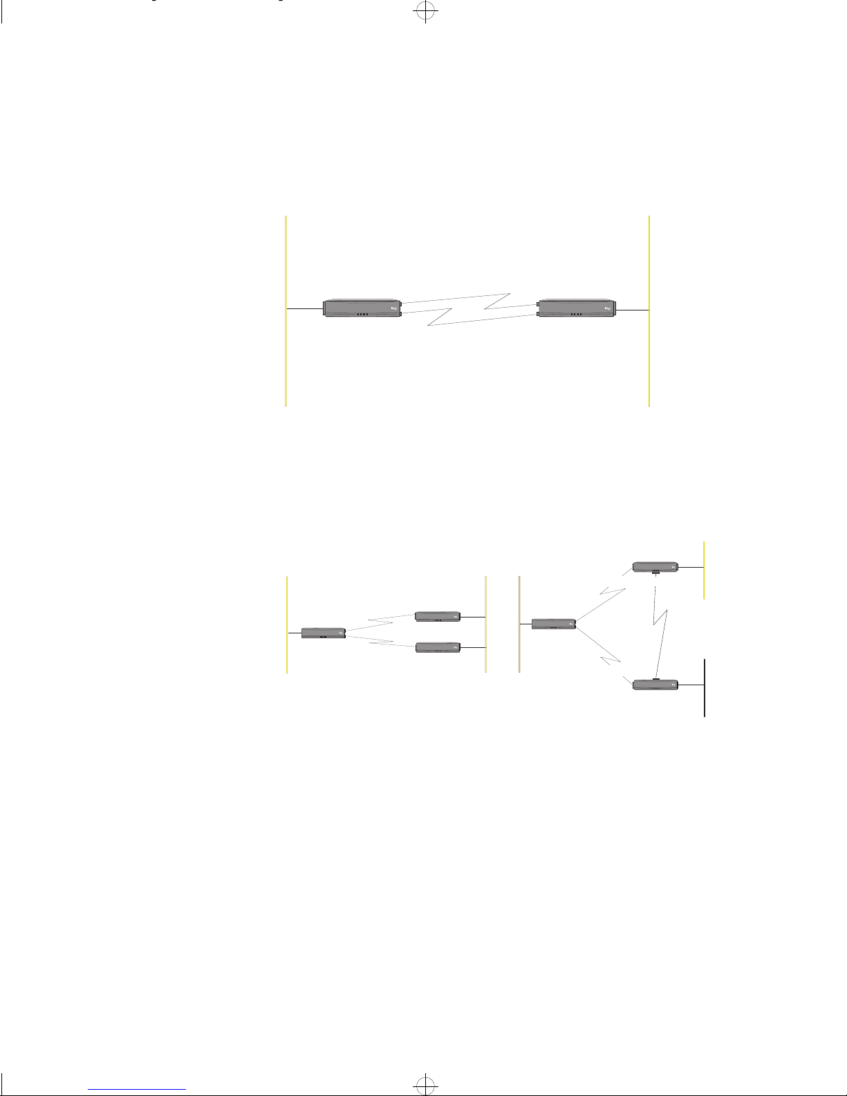
Timecut backup links
considerations
Timecut mode for backup links must only be used if the backup link runs in parallel to the primary WAN link, that is the main WAN link and the backup WAN
link must run between the same routers as shown in the figure below:
LAN2LAN1
Primary WAN Link
LAN WAN1 WAN2 System
Router A
Intel ExpressRouter9200
®
BackupWANLink
(dial-up)
LAN WAN1 WAN2 System
Router B
Intel ExpressRouter9200
®
1476
Timecut mode MUST NOT be selected for backup links that run via a different
router than the main WAN link as shown below. Problems otherwise occur when
using the backup WAN Link.
LAN 2
LAN 1
LAN WAN1WAN2 System
RouterA
Primary WAN
IntelExpressRouter9200
®
BackupWAN
LAN 2
Link
LAN WAN1WAN2 System
RouterB
LAN WAN1WAN2 System
RouterC
IntelExpressRouter9200
®
IntelExpressRouter9200
®
Link
TheBackup WAN Link mustNot use
timecutmode
LAN 1
Primary WAN
IntelExpressRouter9200
LAN WAN1WAN2 System
RouterA
Primary WAN
®
Link
Link
LAN WAN1WAN2 System
RouterB
LAN WAN1WAN2 System
RouterC
IntelExpressRouter9200
®
Backup
WAN Link
IntelExpressRouter9200
®
LAN 3
1475
5
Page 18
LAN and WAN Services in the Router
WAN Services
Multiple backup links
Timer Profiles
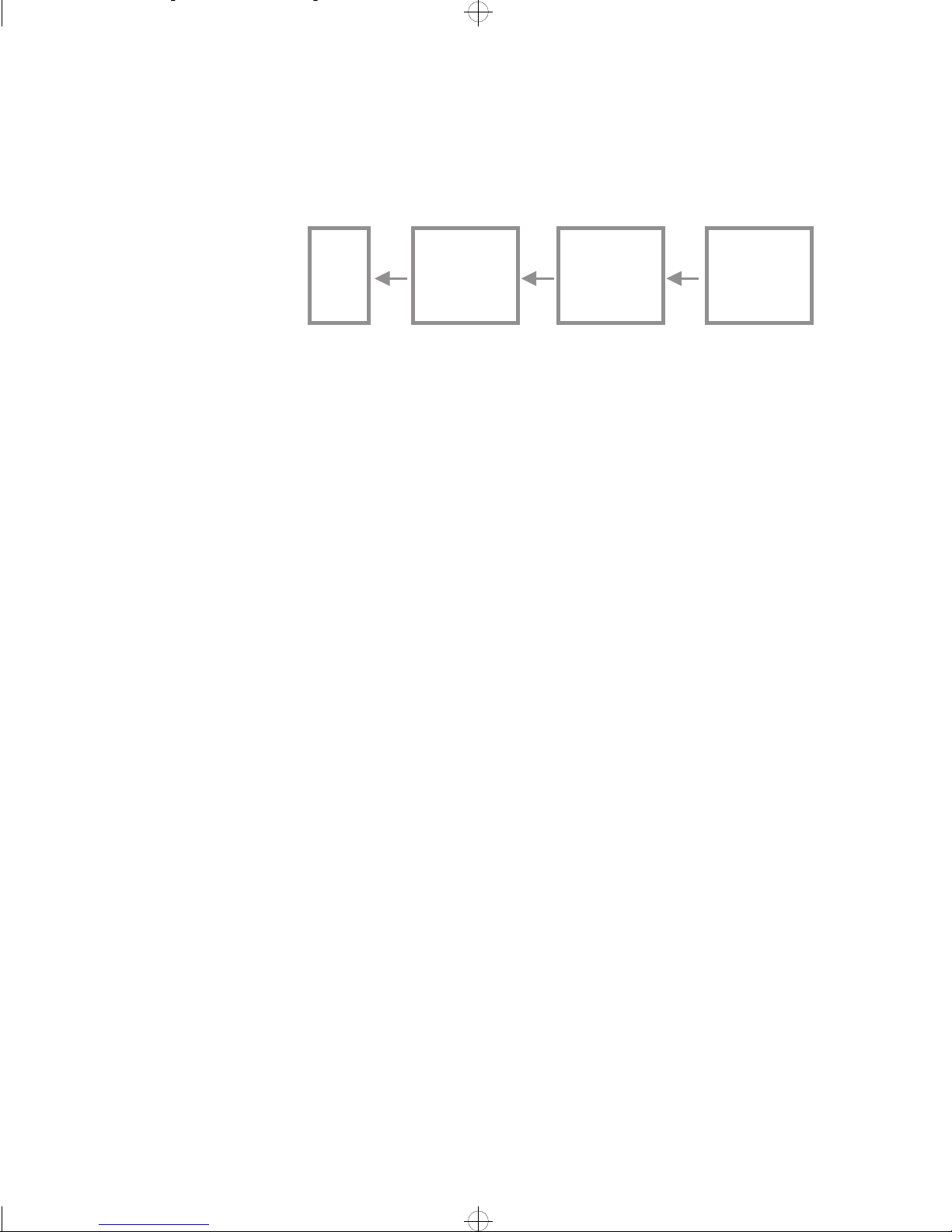
For ISDN and X.25 services, it is possible to establish multiple backup links for
increased internetwork reliability. This can be a particularly useful feature in
X.25 networks where a number of Switched (dial-up) links can be available.
Link 2
PPP
Leased
Line
Link 4
X.25
Dial Up
Backup for Link 2
Link 5
X.25
Dial Up
Backup for Link 4
Link 6
X.25
Dial Up
Backup for Link 5
1235
In the above example, link 4 is used if the primary link (link 2) should fail, link
5 is used if link 4 should fail and link 6 is used if link 5 should fail.
The Intel Express 8100 Router implements Timer Profiles which offer extensive
facilities to restrict WAN link activity according to a user-defined time profile.
This may be done for security reasons or to reduce the operating costs of WAN
links.
Up to 16 user-defined timer profiles can be defined, any one of which can be selected for use with a WAN link during configuration of the link. Each profile allows you to define access rights on a weekly basis, with a half-hour resolution.
For each link, access can be blocked:
Timer profiles
consideration
■
for outgoing access from the router to the WAN link
■
for both outgoing and incoming access (WAN link disabled outside the times
defined in the timer profile)
For example, for one link using a timer profile, outgoing access may be block,
while for another WAN link using the same timer profile, access may be block
for all data traffic.
Warning When blocking both outgoing and incoming access, the timer pro-
file must be the same in both the routers over the WAN link.
This is particularly important for dial-up (switched) WAN links where operating
costs are dependent on the use of the link.
If the timer profiles are not the same and only one of the routers is denying incoming access at some time, the other router may continually attempt to establish
the WAN link. This can lead to the following problems for the calling router:
■
for dial-up WAN links, excessive operating costs for the WAN link
■
error messages being logged
■
the link being disabled (faulted)
6
Page 19

LAN and WAN Services in the Router
WAN Services
Example use of a timer
profile
Daily Activity Limit
For example, a timer profile could be set up to deny both incoming and outgoing
access on a WAN link outside normal office hours of 7:30 to 17:30, and to deny
all access at weekends.
Time
Day
Sun
Mon
Tue
Wed
Thu
Fri
Sat
0 1 2 3 4 5 6 7 8 9 10 11 12 13 14 15 16 17 18 19 20 21 22 23
Access allowed Mon-Fri
between 7.30 and 17.30
1290
The Intel Express 8100 Router has a Daily Activity Limit function which can be
used to control the use, and therefore the cost of operation, of dial-up WAN
Links. The alarm generates an SNMP Trap and can also be set up to close and
lock the associated WAN link when it has been in the Up (for both call directions)
state for the configured time-period within a day (midnight to midnight). That is,
the activity counter is incremented for both incoming and outgoing calls on the
links. If the link has been locked by the Daily Activity Limit, it stays locked until
it is manually reset from Intel Device View.
When a dial-up link has been locked by the Daily Activity Limit, the router does
not permit outgoing calls on the link until the link has been unlocked again from
Intel Device View. However, the link accepts incoming calls, thereby allowing a
remote connection via the link to unlock the link.
7
Page 20

Leased Lines Links
Chapter 2
In this chapter
The WAN connect protocol used for communicating over leased line WAN connections by the Intel Express 8100 Router is the Point-to-Point Protocol (PPP).
When communicating over leased line connections, PPP runs on top of the Highlevel Data Link Control (HDLC) protocol.
Note PPP is also used for communications over ISDN links (PPP over
ISDN).
This chapter gives an introduction to the Point-to-Point Protocol (PPP) and describes the features of the protocol offered by the Intel Express 8100 Router.
Point-to-Point Protocol (PPP)
Introduction to PPP
The Point-to-Point Protocol (PPP) was designed to enable simultaneous transfer
of network-layer protocols across a point-to-point link. Its main function is to establish a synchronous link connection between routers from any manufacturer.
PPP functions include:
■
encapsulating multi-protocol datagrams
■
establishing, configuring and testing the data-link connection using a Link
Control Protocol (LCP)
■
establishing and configuring bridging and various network-layer communications across the link using Network Control Protocols (NCPs). This is handled by the Internet Protocol Control Protocol (IPCP) for IP, and the
Internetwork Packet Exchange Control Protocol (IPXCP) for IPX and the
Bridging Control Protocol (BCP) for bridging services
■
■
■
authenticating peers using the Challenge Handshake Authentication Protocol
(CHAP) and Password Authentication Protocol (PAP) to ensure that communications are between authorized devices
encrypting and decrypting data transmitted via the link to offer data security
compression/decompression of data to improve the throughput of data
8
Page 21

Leased Lines Links
Point-to-Point Protocol (PPP)
PPP provides transport services for data packet delivery with low overheads and
high throughput. Frame checking at the link-level offers error detection, but error
recovery is taken care of by higher-layer network protocols.
PPP protocols
Link Control Protocol
(LCP)
Operation of PPP
The following diagram shows how the various PPP protocols are embedded:
Compression
Control Protocol
(CCP)
Network Control Protocols (NCPs)
Internet Protocol
Control Protocol
(IPCP)
Encryption ControlProtocol
Challenge Handshake Authentication
Protocol (CHAP)
Link Control Protocol
Internet Packet
Exchange Control
Protocol (IPXCP)
(ECP)
(LCP)
Bridging
Control
Protocol (BCP)
1233
LCP is the lowest layer in the PPP stack and runs on top of the High-level Data
Link Control protocol (HDLC) or Integrated Services Digital Networks (ISDN).
When the HDLC or ISDN protocol has established the link, LCP runs on top of it.
The following protocols form the basis of PPP:
Encapsulation
Network-layer protocols are encapsulated for transmission over WAN links.
Link Control Protocol (LCP)
The LCP takes care of the link connection.
Challenge Handshake Authentication Protocol (CHAP)
The Challenge Handshake Authentication Protocol (CHAP) is available to offer
security (encrypted password protection) against unauthorized access to a PPP
link.
Password Authentication Protocol (PAP)
The Password Authentication Protocol (PAP) is available as an alternative to
CHAP offering security (password protection) against unauthorized access to a
PPP link.
Encryption Control Protocol (ECP)
Data encryption is available when communicating over PPP links. The Encryption Control Protocol (ECP) negotiates and manages data encryption between the
devices over the link.
9
Page 22
Leased Lines Links
Point-to-Point Protocol (PPP)
Note Data encryption is only available in certain models of the Intel
Express 8100 Router. Data encryption is not allowed in some
countries by law.
Compression Control Protocol (CCP)
Data compression is available when communicating over PPP links. The Compression Control protocol (CCP) negotiates and manages data compression between devices over the link.
Network Control Protocols (NCPs)
Each Network Control Protocol negotiates and manages a specific network-layer/bridging protocol.
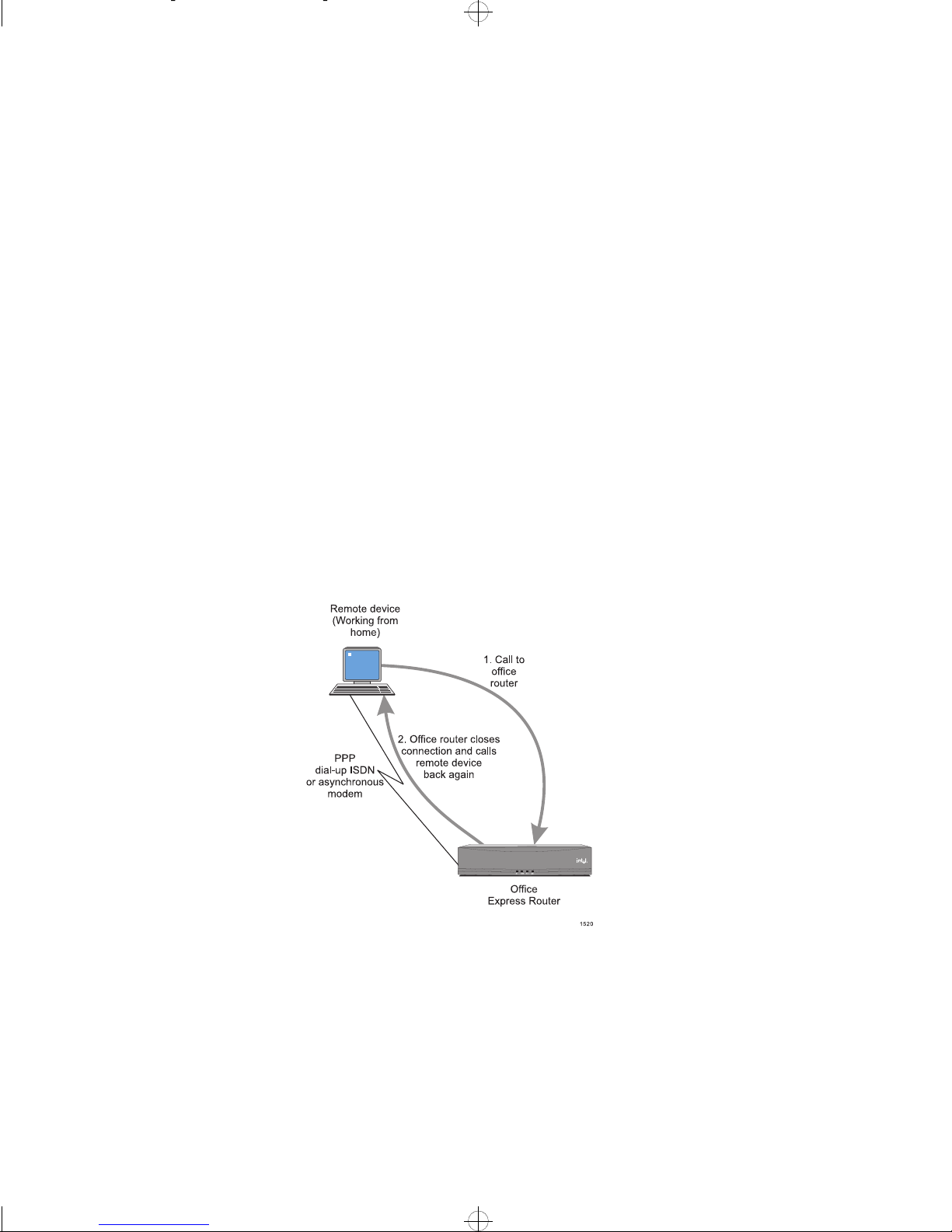
PPP Call Back (PPP
ISDN links)
PPP Call-Back is available for use over PPP ISDN links where the costs of operation of the link can be transferred a specific location.
For example, if someone working from home needs an occasional connection to
the office, the costs of operation for the connection can be transferred to the office by using Call-Back. When the home connection needs to communicate with
the office, they call in to the office Intel Express 8100 Router with a request for
call back and then closes the connection.
Note The router will then return the call. The router must support Call-Back
or the link will not work.
In some cases, Call-Back is used to verify that incoming call is from the authorized address set up for the link.
The Call-Back facility can be used to transfer the cost of operation to either the
local site (this router) or to the remote site.
10
Page 23

Leased Lines Links
Point-to-Point Protocol (PPP)
Multilink PPP
The Intel Express 8100 Router implements PPP Multilink facilities which allow
multiple PPP links between two sites to be used as a single route. A PPP Multilink allows links to added dynamically (for bandwidth-on-demand) or statically
and has almost the combined bandwidth of the individual links.
PPP Multilinks are described in Chapter 6 “PPP Multilinks”, p. 39.
Data Compression
Data compression
Compression algorithm
used
Requirements for use
Data compression is available when communicating over PPP links, to improve
the throughput.
Both routers over the PPP link must support and be configured for PPP data compression for data compression to be used.
The compression algorithm implemented in the Intel Express 8100 Router is
based on the Stac* algorithm developed by Stac Electronics Inc. Typical compression rates of 4:1 are achieved for text data.
The devices at both end of the PPP link must implement the Compression Control Protocol (CCP) and use the same compression algorithm.
Data compression is negotiated by the CCP whenever the link is established. If
the device over the PPP link does not support the CCP or the same compression
algorithm, compression cannot be used over the link.
Link speeds
Data Encryption
Introduction
Encryption algorithm
used
Data compression can be used on combined link speeds of up to 256 kbps (for
example compression can be used on one PPP link of 256 kbps or on two PPP
links of 128 kbps). The delays involved with compressing the data make it impractical to use at higher link speeds.
The Intel Express 8100 Router offers encryption/decryption of data being transmitted over PPP and Frame Relay links. This offers security in case of interception by an unauthorized source.
Note Data encryption is only available in certain models of the Intel Express
8100 Router which are not available in some countries.
The data encryption algorithm implemented in the Intel Express 8100 Router is
Blowfish with a variable length encryption key (up to 144 bits) with 16 rounds
(encryption steps). The algorithm is used in Cipher Block Chaining (CBC) mode
11
Page 24

Leased Lines Links
Point-to-Point Protocol (PPP)
which means that the algorithm is used across the entire data stream including the
packet header containing the address and protocol identification, and not only on
a fixed block (packet) size.
Reference for the
encryption algorithm
Requirements for use
Link speeds
Encryption and
compression
The Blowfish encryption algorithm is described in:
Bruce Schneier
Applied Cryptography (John Wiley & Sons)
The devices at both end of the PPP link must implement the Encryption Control
Protocol (ECP) and use the same encryption algorithm.
Data encryption is negotiated by the ECP whenever the link is established. If the
device over the PPP link does not support the ECP or the same encryption algorithm, the link is disconnected and a message is entered in the System Log for the
router—data communications are not allowed on a PPP link intended for secure
communications.
Encryption can be used on all link speeds and can also be used in conjunction
with compression. The algorithm can encrypt at around 1.3 Mbps, which may
cause delays on combined link speeds above this (for example on a 2.0 Mbps
links).
Data encryption can be used together with data compression (see “Data Com-
pression”, p. 11) over a PPP link. Data is first compressed then encrypted. When
encryption is used in connection with data compression over a PPP link, the restrictions on link speeds for data compression apply.
Peer A uthentication using the Challenge Handshake Authentication
Protocol (CHAP)
Introduction to CHAP
Passw ords
12
The Challenge Handshake Authentication Protocol (CHAP) can be used to provide link security against unauthorized access. CHAP uses password encryption
where passwords can be global (used for all PPP links) or selected from a password pool. Separate passwords can be used for incoming and outgoing calls on a
link.
CHAP uses password encryption to authenticate peers; separate passwords can
be used for incoming and outgoing calls. The passwords are used to encrypt random text files which are transmitted over the PPP link (see ‘Challenge handshake
authentication procedure’ following); passwords are therefore never transmitted
directly over a PPP link, and cannot be intercepted and used by unauthorized
sources.
Page 25

Leased Lines Links
Point-to-Point Protocol (PPP)
Use of passwords
For the correct operation of PPP links using CHAP, the passwords must be configured as follows:
Device 1 (User ID1)
Password A
used for
CHAP requests
Password B
used in reply to
CHAP requests
from User ID2
Request
Reply
Request
Reply
Device 2 (User ID2)
Password A
used in reply
to CHAP requests
from User ID1
Password B
used for
CHAP requests
1338
If Device 1 has Password A configured for CHAP requests on the PPP link, Device 2 must reply to the request using Password A. That is, Password A must be
defined in Device 2 for CHAP replies to Device 1.
Similarly, if Device 2 has Password B configured for CHAP requests on the PPP
link, Device 1 must reply to the request using Password B. That is, Password B
must be defined in Device 1 for CHAP replies to Device 2.
Global (all PPP links)
and Local replies to
CHAP requests
CHAP requests from the
router
A device always tries to reply to a request for authentication from a peer, using
the password defined for the User ID of the peer.
In the Intel Express 8100 Router, a list of passwords for User IDs can be defined
for both the router (global) and for individual PPP links. The passwords in the
global list can be used in reply to CHAP requests from peers on any of the PPP
links to the router. The passwords in the local list can only be used for peers on
the PPP link for which they are defined. The router first tries to find the User ID
of the peer requesting authentication in the local password list and then in the global password list.
In some devices, a common User ID with different passwords are used for communications over a PPP link. In these cases, local User IDs and password should
be defined. Otherwise, global User IDs and passwords can generally be used.
When CHAP requests are enabled, the Intel Express 8100 Router authenticates
the peer over the PPP link whenever the link is established. For on-demand
(switched) PPP links including ISDN links, the router authenticates the peer
whenever the link is brought up.
13
Page 26
Leased Lines Links
Point-to-Point Protocol (PPP)
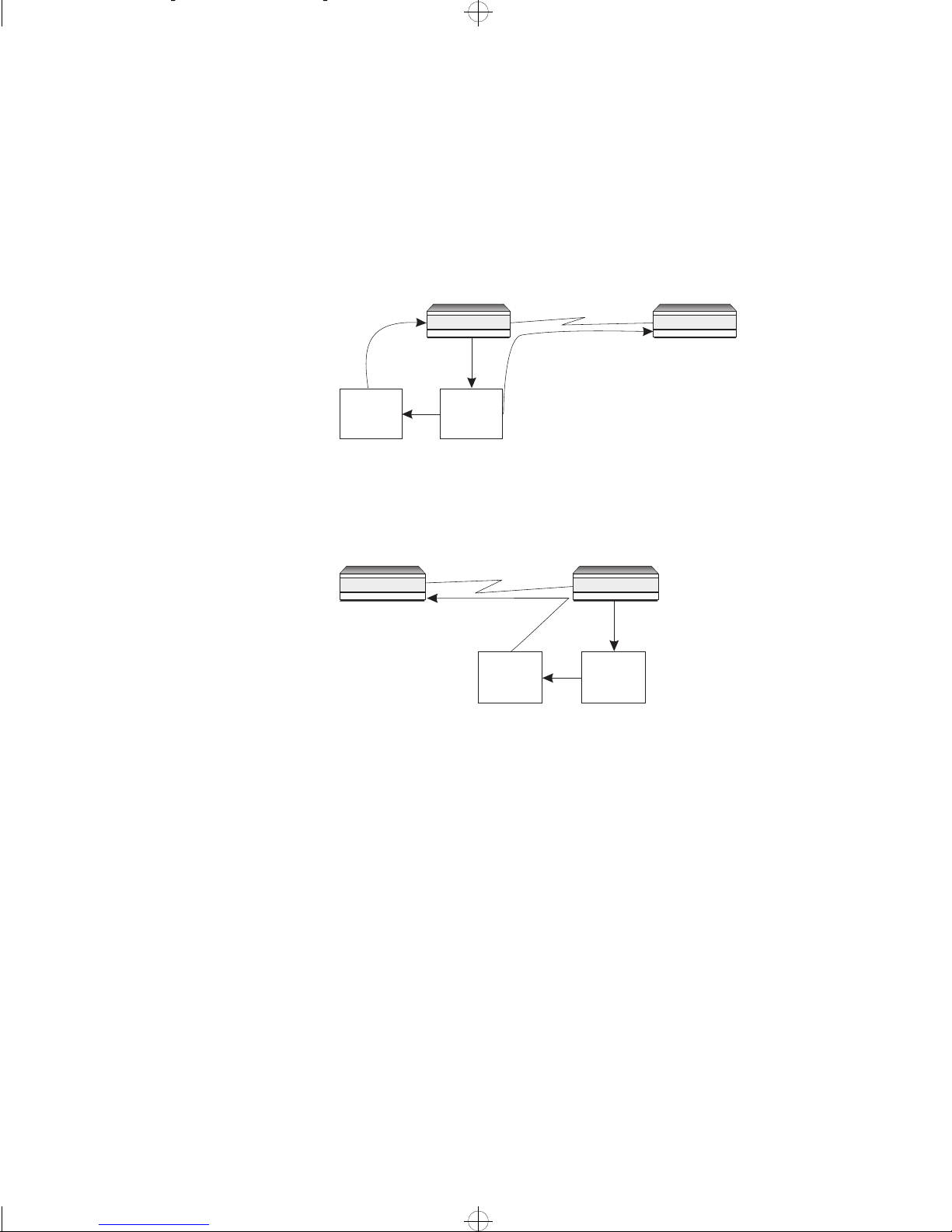
Challenge handshake
authentication procedure
The procedure used to authenticate a peer over a PPP link is as follows:
1 The device which is authenticating the peer (Device 1) generates a random
text file (random characters and a random length), and transmits it to the
device to be authenticated (Device 2) over the PPP link. Device 1 also
stores a copy of the random text file which is encrypted using the password
defined for CHAP requests on the link (Password 1).
Encrypted
using
Password 1
Device 1
Random
text file
PPP Link
2 The device receiving the random text file (Device 2) encrypts it using the
Device 2
Device being
authenticated
1335
password (Password 2) defined for requests from Device 1, then transmits
the encrypted text file back to Device 1.
Device 1
PPP Link
Device 2
Encrypted
using
Password 2
Random
text file
1336
14
Page 27
Leased Lines Links
Devi
Devi
Point-to-Point Protocol (PPP)
3 Device 1 compares the locally encrypted text file with the text file
encrypted by Device 2. If the text files are the same (Password 1 = Password 2) Device 2 is authenticated. Otherwise, Device 2 is not authenticated
and data communications with Device 2 are not allowed.
Peer is
authenticated
Peer is NOT
authenticated
Random
text file
encrypted
Device 1
Random
text file
encrypted
Device 1
ce 1
=
=
PPP Link
Random
text file
encrypted
Device 2
Random
text file
encrypted
Device 2
ce 2
1337
Peer Authentication using the Password Authentication Protocol
(PAP)
Introduction to PAP
The Password Authentication Protocol (PAP) can be used as an alternative to
CHAP to provide link security against unauthorized access. PAP uses simple
password protection against unauthorized access.
PAP versus CHAP
Replies to PAP requests
CHAP uses password encryption to authenticate peers and the passwords are
never transmitted directly over the PPP link, and therefore cannot be intercepted
and used by unauthorized sources. PAP uses simple password protection where
the password is transmitted directly over the link—PAP is therefore not resilient
to link monitoring.
Note For the best security, you should use CHAP rather than PAP for link
access protection wherever possible.
PAP can however be used when it is the only authentication protocol supported
by the remote device.
A device (for example the Intel Express 8100 Router) always tries to reply to a
request for authentication from a peer, using the password defined for the User
ID of the peer.
15
Page 28

Leased Lines Links
Point-to-Point Protocol (PPP)
PAP requests from the
router
When PAP requests are enabled, the Intel Express 8100 Router authenticates the
peer over the PPP link whenever the link is established. For on-demand
(switched) PPP links including ISDN links, the router authenticates the peer
whenever the link is brought up.
If the device over the PPP link fails to authenticate itself, communications over
the link are not allowed.
16
Page 29

Frame Relay Services
Chapter 3
Frame Relay in the Intel
Express 8100 Router
Frame Relay
Features
Frame Relay is available in the Express 8100 Router with Frame Relay. The
WAN port must be configured as a Frame Relay port before it can be used for
Frame Relay services.
As Frame Relay uses Permanent Virtual Circuits, a number of Frame Relay links
can be made via the same Frame Relay port. The Intel Express 8100 Router supports up to 5 Frame Relay links.
This chapter gives an introduction to Frame Relay services in the Intel Express
8100 Router.
Frame Relay is an interface specification that provides a signalling and data
transfer mechanism between endpoints (routers) and the network (switches).
Data to be transmitted are encapsulated according to the Multiprotocol Encapsulation Implementation Agreements of the Frame Relay Forum. It provides efficient network services and accommodates burst-intensive applications over wide
area LAN interconnections at rates up to 2.048 Mbps. Frame Relay provides
bandwidth on demand and allows multiple simultaneous data sessions (logical
channels) across a physical Frame Relay port.
Frame Relay can be very cost-effective when used to interconnect several sites.
Frame Relay allows several logical links to different sites across one physical
Frame Relay port.
Features of the Frame Relay protocol include:
■
■
■
■
■
■
■
■
Provides a connection-oriented service
Maintains data sequence
Connects end-systems at data link layer
uses variable length packets
no data link control, no retransmissions
makes use of LAPF core functions
standard multiprotocol encapsulation
reduced costs for internetworking in large networks
17
Page 30

Frame Relay Services
■
increased interoperability as it complies with international standards
Addressing
Encapsulation
PVC management
Each data packet contains a circuit number, also called a Data Link Connection
Identifier (DLCI), showing which logical channel that the information belongs
to. Frame Relay packets are routed to their destination on the basis of the circuit
numbers contained in the packet.
Note When using Frame Relay, ensure that your network provider allocates
you the necessary DLCI values. DLCI values assigned during Frame
Relay connection, range from 16 up to 991.
Multiprotocol encapsulation according to FRF.3, specifying the protocol contained in the current Information field (I-field). This encapsulation is also specified in RFC-1490 “Multiprotocol Interconnect over Frame Relay Data Terminal
Equipment”, and is compatible with routers from other manufacturers.
Status information between Frame Relay network switches and user devices (for
example routers and bridges) is provided by signalling protocols defined by the
Frame Relay standards committees. These signalling protocols perform the following tasks:
■
providing a ‘heartbeat’ or ‘keep-aliv e’ message e xchange to ensure that links
are available
■
informing about added and removed PVCs
■
providing status of existing PVCs
Frame Relay elements
Frame Relay services may be broken down into three distinct elements:
Frame Relay access equipment
Frame Relay access equipment is customer premises equipment (CPE) which
sends information across the network. This may be, for example, a router, a
bridge, a host computer, and so on.
Frame Relay switching equipment
Frame Relay switching equipment is responsible for the transportation of information across a WAN. This may be, for example, T1 (1.5 Mbps) and E1 (2 Mbps)
packet switches, and so on.
Public Frame Relay services
Public Frame Relay services see the deployment of Frame Relay switches via the
Public Data Network (PDN). If you do not make use of public services (subscribed), private networks may be established. In this case, the private network
must have Frame Relay switching equipment installed.
Note Frame Relay can only be used on high-quality transmission lines dedi-
cated to Frame Relay.
18
Page 31

Frame Relay Services
Data compression
Data encryption
Advantages of Frame
Relay over leased line
links
Data compression is available when communicating over Frame Relay links, to
improve the throughput on link speeds of up to 256 kbps. Typical compression
rates of 4:1 can be achieved for text data.
Both routers over the Frame Relay link must support and be configured for Frame
Relay data compression before data compression is used.
Intel Express 8100 Routers use the Stac algorithm developed by Stac Electronics
Inc. Typical compression rates of 4:1 are achieved for text data.
The Intel Express 8100 Router offers encryption/decryption of data being transmitted over Frame Relay links. This offers security in case of interception by an
unauthorized source.
Note Data encryption is only available in certain models of the Intel Express
8100 Router which are not available in some countries.
Data encryption over Frame Relay links uses the same encryption algorithm and
implementation as for PPP links, see “Data Encryption”, p. 11.
Note Unlike PPP links, Frame Relay links are unable to detect a mismatch in
the encryption keys in the routers over the link. If the encryption keys
are wrong, data will not be un-encrypted and will contain errors (illegal
packets).
Frame Relay uses standardized encapsulation of protocols and it is therefore possible to connect to third-party routers (routers from other manufacturers). When
using Frame Relay, virtual circuits are established allowing for any-to-any connectivity. Both of the mentioned features are not available for a leased line.
19
Page 32

Chapter 4
ISDN Services
Integrated Services Digital Network (ISDN) in the
Intel Express 8100 Router
ISDN in the Intel Express
8100 Router
Point-to-Point Protocol
(PPP)
ISDN links
Basic Rate Access (BRA) ISDN is supported by the following routers:
Express 8100 Router with an ISDN S/T port
which establishes a Basic Rate Interface (BRI) via an ISDN S/T inteface to an
NT-1 termination of the ISDN line
Express 8100 Router with an ISDN U port
which establishes a Basic Rate Interface (BRI) via an ISDN U interface directly
to the incomming ISDN line.
The link protocols used over ISDN links by the Intel Express 8100 Router is the
Point-to-Point Protocol (PPP). PPP is also be used for communicating over
leased line and dial-up (switched) links.
An overview of PPP and the facilities available is given in Chapter 2 “Leased
Lines Links”, p. 8.
For the ISDN Intel Express 8100 Routers, it is possible to configure more ISDN
links (router links) than the number of B-channels available. In this case, ISDN
B-channels can be allocated to ISDN links as follows:
Reserved ISDN B-Channels
ISDN links in the router can be configured to reserve an ISDN B-channel. In this
case, the ISDN link reserving the B-channel always has a B-channel available.
The B-channel reserved by the ISDN link cannot be allocated to another ISDN
link when not in use.
Dynamically allocated ISDN B-Channels
For ISDN links which do not have a reserved ISDN B-channel, a simple link pool
system is used. ISDN B-channels which are not reserved by ISDN links are obtained and returned to the B-channel pool as required by the ISDN links.
20
Page 33

ISDN Concept
ISDN Services
ISDN Concept
What is ISDN?
What ISDN offers
Channel types
ISDN is a digital telecommunications network that allows you to send all kinds
of information, including speech and data, in much the same way as making a
telephone call. The ISDN is digital from end-to-end which improves the data
communications quality and restricted information rate resulting from the use of
analog links together with modems.
CCITT has defined an ISDN as a network, in general evolving from a telephony
Integrated Digital Network (IDN), that provides end-to-end digital connectivity
to support a wide range of services, including voice and non-voice services, to
which you have access by a limited set of standard multi-purpose user-network
interfaces.
ISDN offers multiple 64 kbps or 56 kbps connections on demand with a low error
rate. This can be used in place of leased line WAN links or as a backup to leased
line WAN links. A main advantage of ISDN is that a modem is not required—
the router can be connected directly to the ISDN.
There are two types of channels used in ISDNs:
■
B-channels
64 kbps or 56 kbps full duplex, synchronous channels for data and voice
transfer
■
D-channels
16/64 kbps signalling channels
Connection types
There are two types of connectivity:
Basic Rate Access (2B+D)
This type of connection provides two independent data (B) channels (56 kbps or
64 kbps), and a 16 kbits signalling (D) channel which is provided for communication between the router and the ISDN exchange. It is used to set up and clear
calls for both information channels. This arrangement is called 2B+D and is
equivalent to two independent telephone lines each with a 64 or 56 kbps capacity.
Up to eight terminals can be connected to the line, although only two calls can be
in progress at any one time (each using a B-channel).
Primary Rate Access (30B+D)
This type of connection is used for connecting Private Branch Exchanges (PBX)
to the ISDN. In most countries, Primary Rate Access has 30 B-channels (56 kbps
or 64 kbps) and one D-channel (64 kbps). In the USA and Japan a 23B+D arrangement is used.
Note The Intel Express 8100 Routers offer Basic Rate Access (BRA) only.
21
Page 34

ISDN Services
ISDN Services
ISDN Services
Three types of service
Bearer Services
Tele Services
ISDN services are divided into three categories:
■
Bearer Services
■
Tele Services
■
Supplementary Services
These are the basic transport services which transfer information between the terminal/net interface. That is a connection must be set up between two routers before communication can take place. There are two types of Bearer services:
Circuit switched
These are the simplest types of Bearer services. Once a connection is established,
data is transferred over the link (B-channel) at a rate of 64 kbps (or 56 kbits for
some ISDNs).
Packet switched
If the data rate is variable, then it may not be cost-effective to pay for an
end-to-end channel for the duration of the call. In this case, data is sent in packets
and the cost is based, partly, on the volume of traffic rather than the duration of
the call.
These define the way in which certain standardized applications use ISDN. The
following services are defined by CCITT:
Telephony
Provides two-way, real-time speech conversation. There are two types:
22
■
3.1 kHz
■
7 kHz, which provides speech and sound transmission of a much higher
quality than 3.1 kHz telephony
Teletex
Enables subscribers to exchange character-coded documents automatically. It is
much faster than Telex and has a much larger character set.
Telefax 4
Provides high-speed, high-quality facsimile transmission.
Mixed Mode
This is a combination of Teletex and Telefax 4.
Videotex
Provides retrieval and mailbox functions for text and graphic information.
Page 35

ISDN Services
ISDN Services
Telex
Provides interactive text communication. It is the same as the existing Telex service. The advantage of using it via ISDN is that it can be provided over an interface shared with other services.
Message Handling System (MHS)
Allows you to send and receive electronic mail via a “post box”.
Supplementary Services
A Supplementary Service modifies or supplements a basic service. It may provide additional control functionality or provide information about an ISDN call.
Some of the Supplementary Services available are:
Multiple Subscriber Number (MSN)
Allows more than one number to be assigned to a line. Typically, a block of ten
numbers is assigned with the last number used to select the station.
Sub-addressing (SUB)
Allows you to specify extra addressing information in addition to the ISDN number.
Direct Dialing In (DDI)
Allows an ISDN station to call on an ISPBX directly without the operator.
User-to-User Signalling (UUS)
Allows you to send or receive a limited amount of information to or from another
station over the D-channel in association with an existing call.
Calling Line Identification Presentation (CLIP)
The called party can choose to be presented with the calling party’s ISDN number.
Calling Line Identification Restriction (CLIR)
The calling party can suppress the presentation of his ISDN number to the called
party.
Connected Line Identification Presentation (COLP)
The calling party can be presented with the ISDN number of the called party. It
tells the calling party who actually answers the call (for example if call forwarding is in operation).
Connected Line Identification Restriction (COLR)
The called party can suppress the presentation of his ISDN number to the calling
party.
Closed User Group (CUG)
Allows a group of users to appear to be in their own private network.
Terminal Portability (TP)
Allows a terminal to be unplugged from one socket on a Basic Rate Access connection (S bus) and plugged into another socket on the same S bus without the
call being cleared.
Call Waiting (CW)
Gives notice of an incoming call even if all channels are occupied.
23
Page 36

ISDN Services
ISDN Numbering and Addressing
Call Hold (HOLD)
Allows you to interrupt a call and return to it later.
Line Hunting (LH)
Allows incoming calls to a specific number to be distributed over a group of
lines.
Call Forwarding (CF)
Causes an incoming call to be sent to another number.
Call Transfer (CT)
Allows either the calling or called party to transfer the call to a third party.
Add on Conference Call (CONF)
Allows additional subscribers to be added to a call to form a conference.
Three-Party Service (3PTY)
Allows you to switch between two calls.
Advice of Charge (AOC)
Gives call charge information.
ISDN Numbering and Addressing
Introduction to ISDN
numbering
E164 format
Like the Public Switched Telephone Network (PSTN), Integrated Services Digital Networks (ISDNs) uses Directory Numbers (DNs) to identify subscribers.
The International Telegraph and Telephone Consultative Committee (CCITT) a
numbering plan for ISDN (Recommendation E164) which specifies how numbers should be constructed within telephone networks. E164 includes the existing
plan E163 for the PSTN—both ISDN and PSTN numbers can therefore be allocated out of the same range of numbers.
Each ISDN directory number specifies a point of connection to the network (an
ISDN line). Each line can, however, support more than one terminal—see “BRA
and PRA Numbering”, p. 26
The number consists of a maximum 15 digits and is divided up in the following
way:
Country Code (CC)
This consists of 1-3 digits.
National Significant Number (NSN)
This consists of between 12-14 digits. This is sub-divided further into a:
■
National Destination Code (NDC)
■
24
Subscriber Number (SN)
In Denmark, for example, the NSN is 8 digits long; NDC = 2 digits and the
SN = 6 digits.
Page 37

Sub Address (SA)
This consists of between 1-40 digits.
ISDN Services
ISDN Numbering and Addressing
Addressing
Address checking
An incoming call can contain the following address fields:
Calling Party Number
Local Address of the Calling router (address corresponds to the Remote Address of the
Calling Party Sub-address
Called router).
Local Sub-address of the Calling router (address corresponds to the Remote
Sub-address of the
Called Party Number
Called router).
Local Address of the Called router (address corresponds to the Remote Address
Calling router).
of the
Called Party Sub-address
Local Sub-address of the Called router (address corresponds to the Remote
Sub-address of the
Calling router).
Some of the address fields may be absent depending on the network and supplementary services available.
The router accepts the call when both the destination and source address checks
succeed.
To ensure a one-to-one relationship between end devices, a unique ISDN number
is assigned to each link across the ISDN. Incoming calls are only accepted if the
local and remote addresses and sub-addresses match as shown below:
Destination address and
sub-address check
Addresses must match for a call to be accepted
Calling Device Receiving Device
Local Address Remote Address
Remote Address Local Address
Remote sub-address Local Sub-address
Note ISDN addresses can be changed by intermediate ISDN switches in the
ISDN network.
Some of the addresses may not be used by an ISDN variant particular to some
countries (for example the sub-address), in which case the check of that address
is omitted.
The router only accepts an incoming call when the ISDN Remote Address
matches the Local Address, and the Remote Sub-address (if used) matches
Local Sub-address of an ISDN link in the router.
the
25
Page 38

ISDN Services
ISDN Numbering and Addressing
If a Local Address is not defined for an ISDN link, all incoming addresses are
accepted by the link (the address check is not performed). Similarly, if a
Sub-address
is not defined for an ISDN link, all incoming sub-addresses are
Local
accepted by the link (the sub-address check is not performed).
If the network does not provide the sub-address service, then a
dress
must not be defined (left empty).
Source address check
Source address checking adds security to the WAN link—the router only accepts
an incoming call when the source address matches the
figured for the ISDN link.
ISDN switches may change address prefixes. To support all ISDN implementations, the address check is made from right to left using the number of digits defined for the
There are occasions when the source address and/or sub-address is missing from
incoming calls (some ISDN networks do not provide presentation of the source
address in incoming calls). In these cases, the router omits the check of the source
address and accepts the calls—there is no security check on these calls.
BRA and PRA Numbering
More than one terminal
supported by ISDN line
The ISDN Directory Number (DN) specifies a point of connection to the network
(an ISDN line). Each ISDN line, however, can support more than one terminal.
This is done in two different ways:
BRA (Basic Rate Access)
Each ISDN line can support more than one terminal directly.
Local Sub-ad-
Remote Address con-
Remote Address Check parameter.
Either B-channel (if both
are free) for incoming call
(BRA)
Any free B-channel for
incoming call (PRA)
26
PRA (Primary Rate Access)
Each ISDN line can support more than one terminal through an ISPBX (Integrated Services Private Branch Exchange) or multiplexer.
There are therefore a number of mechanisms specified to allow an incoming call
to be directed to a particular terminal on a given line.
Normally a BRI has a single DN and the exchange can use either B-channel (if
both are free) to deliver an incoming call to a terminal.
Normally a PRI has a single DN and the exchange can use any free B-channel for
an incoming call.
Page 39

MSN (Multiple Subscriber Number)
ISDN Services
ISDN Numbering and Addressing
Different Directory
Number (DN) for each
terminal
Each line is allocated a block of DNs, typically 10, and when there is an incoming
call, the called number is presented to all the terminals on a passive bus.
Each terminal is programmed to respond to a different DN and thus the correct
terminal is able to answer the call.
More than one call at
same time
If the attached device is capable of handling more than one call at the same time,
for example an Intel Express 8100 Router with multiple ISDN links, then it can
be programmed to respond to more than one number.
Calling Line Identification
The Calling Line Identification supplementary service is a country-dependent
default service for EuroISDN. A
work when setting up a call. This is checked by the network and, if valid, passed
on to the
SUB (Sub-addressing)
One or more identifiers
for each terminal
This is the most flexible form of terminal identification. Each terminal on a line
is given one or more identifiers, each of which is a unique string of characters of
your choice.
Each of the terminals on a passive bus has its own sub-address, and all of the terminals share the same ISDN number. An Intel Express 8100 Router with multiple ISDN links must have a separate sub-address for each ISDN link.
Calling terminal can present its DN to the net-
Called party.
String supplied by caller
In order to specify a particular terminal or an ISDN link in the Intel Express 8100
Router, the caller supplies the appropriate character string to the network when
the call is made.
The network passes this string unchanged (subject to any restrictions on length
and character set) to the called line.
DDI (Direct Dialing In)
ISPBX extension
numbers
This is a facility whereby the last few (typically 3) digits of the Directory Number
(DN) are used to specify which extension of an ISPBX is being called.
The BRA/PRA (or group of BRA/PRAs) to which the ISPBX is connected is allocated a block of numbers.
When there is an incoming call, the last few digits of the number are presented to
the ISPBX to allow it to select the correct extension.
27
Page 40

ISDN Services
Permanent ISDN
Example
A customer could be allocated all numbers in the range 678000 to 678999.
A call to any of these numbers would be routed to the same BRA/PRA, the ISP-
BX being responsible for directing the call to the appropriate extension, these being numbered from 8000 to 8999.
Calling Line Identification
The Calling Line Identification supplementary service is a default service for EuroISDN. For outgoing calls, the ISPBX can provide the DDI number of the originating extension for presentation to the called subscriber.
Permanent ISDN
Permanent ISDN
connections
Signalling
In some countries, Permanent links are available over ISDNs which offer a static
association between two sites without the need for the signalling associated with
normal ISDN links. Permanent link are allocated by the ISDN provider and are
similar to leased line WAN links as they are always available for data transfers.
No signalling or dialing is required for Permanent ISDN connections. Permanent
ISDN links operate on Layer-1 only—Layer-2 and Layer-3 are not used by Permanent ISDN.
Permanent ISDN link
types available in the
router
The Permanent ISDN link types available in the Intel Express 8100 Routers with
a Basic Rate Interface (BRI) are:
■
■
Permanent ISDN connections using the D-channel are not supported.
These modes of operation for the ISDN Basic Rate Interface are selected on the
Advanced screen for the ISDN port.
ISDN Standards
A common standard
It should be possible to buy a piece of equipment anywhere in the world, plug it
in anywhere in the world and communicate with anywhere in the world. This is
the main goal of ISDN. However, at the present time, a world-wide ISDN standard does not exist. Each country has its own version of an ISDN standard.
Progress is however being made, especially in Europe.
Permanent 64 kbps or 56 kbps
which offers two 64 kbps or 56 kbps Permanent ISDN links which can be to
different sites.
Permanent 128 kbps or 112 kbps
which offers a single 128 kbps or 112 kbps link to another site.
28
Page 41

ISDN Services
ISDN Standards
ETSI
EuroISDN and National
ISDN-1
ISDN protocol variants
supported
The European Telecommunications Standards Institute (ETSI) was set up to produce European Telecommunications Standards (ETS). Some of these standards
have been designated as NETs (Normes Européen de Télécommunications)
which specify the connection requirements for terminal equipment. The most important are NET 3 and NET 5. These standards are for the type approval of equipment for connection to ISDN BRA and PRA respectively.
In 1989, European network operators signed a Memorandum Of Understanding
(MOU) to enable the standardization of services and user-network interfaces, and
international connectivity.
A variety of national standards currently exist for ISDN in Europe. These are
gradually being replaced by ETSI standards to provide a European-wide service.
The situation is similar in the USA, a similar state of affairs exists resulting in the
National ISDN-1 standard.
A number of country-specific variants of ISDN are currently in use around the
world. The ISDN variants supported by the Intel Express 8100 Router are:
■
Euro ISDN (ETSI)
EuroISDN is used in many countries throughout Europe and Asia Pacific
and in Australia.
■
National ISDN-1 (USA)
■
National ISDN-2 (USA)
Service Profile IDs
(SPIDs)
■
AT&T ISDN (USA)
■
Nortel DMS-100 (USA)
■
NTT (Japan)
■
KDD (Japan)
Service Provider IDs (SPIDs) are used by USA ISDN variants only and are used
to identify to the switch the ISDN services provisioned for the terminal. The
SPID is registered at the switch during link establishment.
Network providers which supply NI1 (National ISDN-1) or AT&T ISDN in the
USA require the use of SPIDs for identification of the services provided. For
Northern Telecom DMS-100 ISDN switches, a SPID is required for each Bchannel of the BRI. That is, if both B-channels of the BRI are to be used, two
SPIDs are required.
29
Page 42

ISDN Services
ISDN Network Interface Reference Configurations
ISDN Network Interface Reference Configurations
Purpose
Reference configurations are used to describe various possible physical interfaces to the ISDN.
TE2
S
TE1
R
TA
RS
NT2 NT1
NT2 NT1
T
Transmission Line
Transmission Line
T
0962
The boxes represent functional groups, each having a set of functions that may
be needed to connect to the ISDN. Reference points (R, S and T) are connections
between functional groups.
The Intel Express 8100 Router with an ISDN S/T port contains the following
physical interfaces:
Express 8100 RouterST
with an ISDN S/T port
30
TE1 NT2 NT1
S
T
ISDN Line
1633
The Intel Express 8100 Router with an ISDN U portcontains the following physical interfaces:
Express 8100 RouterU
with an ISDN U port
TE1 NT2 NT1
S
T
U
ISDN Line
1633
Page 43

ISDN Services
ISDN Network Interface Reference Configurations
Functional Groups
The functional groups are:
■
NT1/2 (Network Termination)
- NT1 terminates the transmission line from the local exchange
- NT2 handles a variety of functions such as multiplexing and switching
■
TE1/2 (Terminal Equipment)
- TE1 has an ISDN interface and terminates an ISDN call
- TE2 is similar to TE1 but does not conform to ISDN recommendations
■
TA (Terminal Adapter—not required for the Intel Express 8100 Router)
Allows a TE2 to be connected to the ISDN. It performs a conversion
between the signalling and user information formats at the R interface and
the ISDN interface. R interfaces are typically V.24 and X.21 interfaces.
31
Page 44

X.25 Services
Chapter 5
In this chapter
X.25 is available in the Express 8100 Router with X.25
The WAN port must be configured as an X.25 port before it can be used for X.25
services.
As X.25 uses virtual circuits, a number of links (virtual circuits) can be made via
the same X.25 port.
This chapter gives an introduction to X.25 services in the Intel Express 8100
Router.
X.25 Characteristics
Introduction to X.25
Packet Switched Data
Networks (PSDNs)
X.25 is an internationally agreed protocol for communications between a LAN
device (for example a router connected via a modem) and the Packet Switched
Data Network (PSDN) node. The packet switched data network can be either a
Public Data Network (PDN) or a privately owned network. X.25 is independent
of the internal protocols used within the Packet Switched Data Network (PSDN).
X.25 uses the OSI standard reference model, and defines standards for layers 1,
the physical layer; layer 2, the data link layer and layer 3, the network layer.
Packet Switched Data Networks work on a store-and-forward principle; data
packets received at a node in the PSDN are stored until it is convenient for the
network to forward them. This is a cost-effective arrangement as PDNs need not
reserve network bandwidth for packet switched connections; packets can be forwarded when the bandwidth becomes available. PSDNs can therefore offer competitive rates for data transfer.
32
Page 45

X.25 Services
X.25 Characteristics
X.25 device
characterization
Physical layer
Link layer
At the physical layer (layer 1 of the OSI reference model), X.25 defines LAN
communications devices (for example a router) as Data Terminal Equipment
(DTE) and PSDN nodes as Data Communication-terminating Equipment (DCE).
X.25 X.25
Packet Switc hed
Data Networ k
(PSDN)
DCE
DTEDCEDTE
1226
The X.25 protocol defines the communication interactions between the DTE and
DCE devices, and is independent of the structure and protocols used between the
two DCE devices and over the PSDN.
X.25 specifies the use of full duplex, point-to-point synchronous circuits for the
physical layer.
The primary responsibility of the link layer protocol is to ensure the error-free exchange of data over a link which has variable delays. The X.25 standard defines
the use of either Link Access Procedure (LAP) or Link Access Procedure, Balanced (LAPB) where LAPB is the preferred link layer protocol and is the protocol implemented in the Intel Express 8100 Router.
Network layer
X.25 network layer (also known as packet layer) services give X.25 its virtual circuit characteristics. In addition to sending and receiving data packets, the network layer is responsible for:
■
establishing and clearing virtual circuits across the PSDN
■
recovering from error conditions (reset and restart procedures)
33
Page 46

X.25 Services and Features
A
X.25 Services
X.25 Services and Features
Service types available
Logical channels
Line speed matching
X.25 allows two basic service access types to a PSDN:
Switched Virtual Circuits (SVCs)
An SVC is a temporary association between two DTEs. This requires that the link
between the DTEs through the PSDN must first be established by making what
is known as a Virtual Call. SVCs are therefore only initiated by a DTE when data
requires transmitting, and are cleared again when the data has been sent. An SVC
is analogous to a dial-up (switched) WAN link between two LANs.
Permanent Virtual Circuits (PVCs)
A PVC is a permanent association between two DTEs; no Virtual Call is required
to initialize the link and the link is not cleared when the data has been sent. A
PVC is analogous to a leased line WAN link.
X.25 uses logical channels when communicating over PSDNs. This means that a
number of logical links (connections) to different remote destinations can be established via one physical X.25 port. For example, an X.25 port (one number)
with 6 logical channels can communicate with 6 remote destinations simultaneously.
The store-and-forward nature of PSDNs means that X.25 requires advanced data
flow control and line speed matching. This means that data can be received at a
different speed than it was transmitted. For example, a host at a central site can
be connected via a 56 kbps X.25 connection to several remote sites which are
connected with cheaper 19.2 kbps X.25 connections.
34
Central
Site
Router
ttachment
Logical connection
X.25
56 Kbit/s
Packet Switc hed
Data Networ k
(PSDN)
X.25
19.2 Kbi t/s
X.25
19.2 Kbi t/s
X.25
19.2 Kbi t/s
Remote
Office
Remote
Office
Remote
Office
1228
Page 47

X.25 Packets and Virtual Calls
X.25 Services
X.25 Packets and Virtual Calls
Supervisory packets
Virtual Call process
In addition to data packets, X.25 uses special supervisory packets to:
■
establish Virtual Calls
■
clear Virtual Calls
■
negotiate packet and window sizes
■
maintain and supervise logical channels across the PSDN
■
recover from error conditions
Many of these X.25 supervisory packets are only used by SVCs.
Virtual Calls are made using supervisory packets to establish virtual circuits
through the PSDN. The Virtual Call process is as follows:
1. The DTE which wishes to establish the Virtual Call sends a Call Request
Packet to the local DCE on the highest free Logical Channel Identifier it has
available for outgoing calls.
The Call Request Packet contains the address of the remote DTE.
2. The PSDN decides if the call is valid; if it is, the DCE forwards the packet to
the appropriate remote DTE via the remote DCE, on the lowest Logical
Channel Identifier available at the remote device.
Calling
DTE
Call
Request
1
2
X.25 X.25
3
4
.
.
n
DCE DCE
Packet Switc hed
Data Networ k
(PSDN)
n
.
.
Called
4
3
2
Incoming
1
DTE
Call
3. If the remote DTE accepts the call, it sends a Call Accepted Packet to the
Logical Channel
Packet Path
1234
DCE (the remote DCE).
The Call Accepted Packet contains the Logical Channel Identifier on which
the call request was received. The association between the Logical Channel
Identifier and the route to the calling DTE has already been established.
35
Page 48

X.25 Services
X.25 Packets and Virtual Calls
4. The remote DCE forwards the call Accepted Packet across the PSDN to the
local DCE which then passes it to the calling DTE. Again, only the Logical
Channel Identifier from the local DCE to the calling DTE is included in the
packet.
Window size
Packet and window sizes
1
2
DTE
Call
3
4
.
.
n
Calling
Connected
Logical Channel
Packet Path
X.25 X.25
Packet Switc hed
DCE DCE
Data Networ k
(PSDN)
n
.
.
Called
4
3
2
Call
Accepted
1
DTE
1236
The window is the number of packets that may be transmitted without receiving
acknowledgment.
As X.25 is based upon LAPB which is resilient to packet loss, the window size
is used for controlling the flow of packets.
For PVCs, the packet and window sizes used when communicating across the
X.25 network are fixed (static) and are defined by the X.25 service provider (typically packet size of 128 bytes and a window size of 2 packets).
36
For SVCs, some X.25 networks allow negotiation of the packet and window sizes
between the DTE and the DCE. The packet and window sizes used are arrived
upon using an algorithm defined by the X.25 standard. Parameter negotiations
can give more efficient data transfers but be aware that some X.25 network providers charge extra for the negotiation services.
For SVCs across X.25 networks or subscriptions which do not allow negotiation,
the packet and window sizes are fixed (static) and are defined by the X.25 service
provider (typically 128 bytes, 2 packets).
Note The packet and window sizes are only used between a DTE and the
DCE. The packet and window size used at the remote DTE and DCE
can be different.
Page 49

X.25 Services
X.25 Addressing
Encapsulation
Data packets for transmission over an X.25 link must be encapsulated. The Intel
Express 8100 Router supports the following encapsulation types:
Single-protocol Encapsulation of Datagrams
The Intel Express 8100 Router allows single-protocol encapsulation of IP or IPX
datagrams for transmission over an X.25 link as specified in RFC 1356. Singleprotocol encapsulation of IP datagrams also conforms to RFC 877 which is an
older standard which only allows the encapsulation of IP datagrams.
When only IP or IPX packets are to be transmitted over an X.25 link, the singleprotocol encapsulation modes reduce the transmission overheads.
Multiprotocol Encapsulation of Datagrams
The Intel Express 8100 Router allows multiprotocol encapsulation of datagrams
for transmission over an X.25 link as specified in RFC 1356. If both IP and IPX
are to be transmitted, multiprotocol transmission must be used. Multiprotocol encapsulation must also be used if bridging is to be supported over the X.25 link.
For multiprotocol encapsulation:
■
IP packets are encapsulated according to RFC 1356 and are identified using
a Hex CC in the header
RFC 1356 also allows SNAP encapsulation of IP packets which is not supported by the Intel Express 8100 Router.
■
IPX packets are SNAP 8137 encapsulated according to RFC 1356
X.25 Addressing
X.121
X.121 number format
X.25 uses CCITT recommendation X.121 “International Numbering Plan for
Public Data Networks” for addressing within international public data networks.
This recommendation specifies how data network addressing (numbering) can be
implemented along side existing international telephone networks.
An entire X.121 number (address) is known as an International Data Number and
consists of from 5 up to 14 digits. The International Data Number can comprise
the following:
Data Network Identification Code (DNIC)
This consists of 4 digits for international data network addressing. The first 3 digits are the Data Country Code (DCC) and identify a specific country. The fourth
digit is known as the network digit and is used to distinguish between different
data network providers (public or private) operating within the country.
Assignment of DCCs is the responsibility of the ITU (previously called the
CCITT). The network digit is assigned nationally.
37
Page 50

X.25 Services
X.25 Addressing
Network Terminal Number (NTN)
Network addresses within a DNIC (a particular data network provider within a
particular country) are called Network Terminal Numbers (NTNs). NTNs identify a DTE/DCE interface and are assigned by the data network provider. NTNs
can be of variable length up to 10 digits, depending on the network provider.
National Number (NN)
Where, for example, an integrated numbering scheme exists within a country and
different network providers are identified within the national numbering scheme,
National Numbers (NNs) can be used instead of Network Terminal Numbers
(NTNs). As National Numbers already identify a data network provider within
the country, the International Data Number therefore consists of the Data County
Code (DCC) plus the National Number (NN).
Therefore, a International Data Number = DNIC + NTN or DCC + NN.
Sub-addressing
Address checking
Destination address
check
Source address check
This can consist of any remaining digits of the 14 digit X.121 number, and in
some countries it can be used for sub-addressing within the International Data
Number, for addressing a number of devices/nodes located at a single International Data Number. This can be used for example, for addressing different links
in the router.
To ensure a one-to-one relationship between end devices, a unique number is assigned to each link across the PSDN. Incoming calls are only accepted if the local
and remote addresses match, as shown in the table below:
Addresses Must Match for a Call to be Accepted
Calling Device Receiving Device
Local Address Remote Address
Remote Address Local Address
The router only accepts an incoming call when the Remote Address matches
Local Address of an X.25 link in the router.
the
Local Address is not defined for an X.25 link, all incoming addresses are
If a
accepted by the link (the address check is not performed).
Source address checking adds security to the WAN link—the router only accepts
an incoming call when the source address matches the
Remote Address con-
figured for the X.25 link.
38
Page 51

PPP Multilinks
Chapter 6
In this chapter
Introduction
Channel bundling
Master link
Slave links
Configuration overview
This chapter gives an introduction to PPP Multilinks in the Intel Express 8100
Router.
The ISDN Intel Express 8100 Routers implements PPP Multilink facilities which
allow multiple PPP links between two sites to be used as a single route. A PPP
Multilink allows links to be added dynamically (for bandwidth-on-demand) or
statically and has almost the combined bandwidth of the individual links.
Combining multiple links into a single route (link) is also sometimes known as
channel bundling.
The master link is the PPP Multilink between two sites and consists of the slave
links that make up the Multilink. The master link is the controlling link between
the two sites, and controls (for example) when the multilink is established or not,
data encryption over the link, peer authentication over the link using CHAP, and
so on.
Slave links are individual PPP links that are defined as part of the master link.
These links are ISDN links which correspond to ISDN B-channel links.
The following shows an example of how Multilink is set up in the router:
The ISDN port on the router must first be configured, the Multilink is configured
to combine ISDN slave links, and then the routing protocols (IP and Novell IPX)
and bridging are configured on top of the Multilink as required.
39
ISDN port
ISDN slave link ISDN slave link
PPP Multilink
IP Routing IPX Routing WAN Bridging
Page 52

PPP Multilinks
Operating modes
The slave links that make a PPP Multilink can be used in two basic operating
modes:
Bandwidth-on-Demand (BOD) Mode
When a slave link of a PPP Multilink is used in Bandwidth-on-Demand mode,
the link is dynamically allocated when the data traffic volume requires its use,
and closed down when not required. This facility offers the most cost-effective
use of dial-up PPP links (including ISDN B-channels) where the cost of operation depend on the time that the link is in use.
Bandwidth-on-Demand can only be done when a slave link is a dial-up
(switched) link such as ISDN B-channels. Leased line PPP links can only be statically allocated, that is they are always available for use by the PPP Multilink.
Slave links
Dynamic slave links
PPP Multilink
Static slave link
1371
The criteria used to open and close Bandwidth-on-Demand links can be:
■
on the amount data awaiting transmission
■
on the amount of received data
■
both the amount of data awaiting transmission and the amount of received
data
Static mode
When a slave link of a PPP Multilink is used in Static mode, the link is always
available for use by the PPP Multilink.
40
Page 53

Internet Tunnels
Chapter 7
Internet Tunnels
Internet Tunnels are not a direct link via a router port but are secure links established via the best IP route to an Internet Service Provider (ISP).
Internet
Service
Provider (ISP)
Internet
Service
Provider (ISP)
Internet
T
T
u
u
t
t
n
n
e
e
n
n
n
n
r
e
r
e
e
e
t
t
n
n
I
Link
to ISP
ExpressRouter8100
Status
LAN
WAN Link
WAN Switch
WAN Control
100 Mbps
Test Mode
I
l
l
ExpressRouter8100
Status
LAN
Link
to ISP
WAN Link
WAN Switch
WAN Control
100 Mbps
Test Mode
1625
Internet Tunnels are a cost effective solution to transferring data between remote
sites; IP and IPX routing and bridging are available over the tunnel as with a conventional WAN links.
The costs of operation of an Internet Tunnel can be very low when compared to
routing via other WAN link types an ISDN link, especially when transmitting
data over long distances. The throughput of the Internet Tunnel is dependent on
the Internet so can be quite slow at certain times of the day.
Note It is strongly recommended that you use the Setup Wizard in Intel
Device View for Windows to set up your first Internet Tunnel. If other
Internet Tunnels require configuring, use the tunnel configured by the
Setup Wizard as a guide.
41
Page 54

Internet Tunnels
Internet Tunnel
considerations
The following considerations must be taken into account when setting up an Internet Tunnel:
IP Routing using RIP over the Internet Tunnel
When using IP RIP routing over an Internet Tunnel a static host route to the remote router via the link from the router to the Internet Service Provider must be
established.
If RIP routing is used without the static host route, the router tries to use the Internet Tunnel as the best route to the remote network. The static host route ensures that the Internet Tunnel is established via the route to the ISP and that all
the data to the remote router is transferred through the Internet Tunnel.
Site Access Security
Access security must be considered when using Internet Tunnels. This can be
achieved using IP filtering to eliminate unauthorized traffic from the link.
Hiding your internal LAN address from the Internet
Dynamic Network Address Translation (NAT) offers the best solution for hiding
your internal LAN from the Internet. See “Network Address Translation
(NAT)”, p. 57.
Data Security using Encryption
The use of data encryption over Internet Tunnels is highly recommended. Private
data being transferred over the public Internet should always be encrypted for security.
The protocol structure of
an Internet Tunnel
Note Data encryption is only available in certain models of the Intel
Express 8100 Router which are available in some countries.
Internet Tunnels have the following protocol stricture:
IP routing IPX routing Bridging
PPP
TCP
IP static host route
42
Page 55

Internet Tunnels
IP routing services then use the best link to the remote IP network (the link via
the Internet Service Provider). For example, this could be an ISDN link, in which
case the full structure would be
IP routing IPX routing Bridging
PPP
TCP
IP static host route
PPP
ISDN port
Data security over X.25
links application of
Internet Tunnels
To allow data security over X.25 links, Internet Tunnels can be used on top of
them. this offers all the security features supported by PPP (data encryption,
CHAP and PAP) on the X.25 links.
Tunnels adding device
authentication and encryption
security to the X.25 links
Express8100Router
Status
Express Router
Express 8100Router
Express Router
X.25 network
(virtual circuits)
X.25 links
Express8100Router
Express Router
1630
To establish a tunnel over an X.25 link, the X.25 link is set up as normal, together
with an Internet Tunnel to the IP address of the remote router over the X.25 link.
Data security is configured on the tunnel as required. A single static route is then
43
Page 56

Internet Tunnels
configured on the X.25 link to the IP address of the remote router (see “Static
Routes”, p. 68). Routing and bridging for data over the link are then configured
on the Internet Tunnel.
X.25 port (WAN port configured for X.25)
X.25 link (PVC or SVC) - Up to 2 links -
Static IP route to the IP address of the router over the
X.25 link
Internet Tunnel
IP Routing IPX Routing WAN Bridging
44
Page 57

Part II
IP, Novell IPX and Bridging Services
Page 58

Page 59

IP Routing
Chapter 8
In this chapter
IP Concept
Concept description
Background
knowledge
References
Address assignment
This chapter describes IP Routing services based upon the Routing Information
Protocol (RIP—both RIP-1 and RIP-2 are supported), and using static routes implemented in the Intel Express 8100 Router.
In an IP environment, any station connected to an IP network is referred to as a
host. IP Routing is based upon RIP (Routing Information Protocol). When IP
packets are routed, they are routed from a source host to a destination network
without knowing if the destination address exists on the destination network.
It is assumed that you are familiar with the terminology and the protocols used in
IP environments.
See the Preface for a list of Requests for Comments (RFCs) concerning IP routing.
An IP address consists of a network part and a host part. The network part of the
IP address must be globally unique and are assigned by InterNIC (International
Network Information Center). However, addresses are often provided by the network provider. For more information about the InterNIC project consult the RFC
1594.
The host part of an IP address is the responsibility of the network manager.
Private networks
BootP broadcasts only
47
In private networks, where connections to other IP networks are not desired, locally assigned network addresses can be used.
In the current IP Routing implementation in the Intel Express 8100 Routers the
only broadcast packets forwarded are BootP broadcasts.
Page 60

IP Routing
IP Concept
Frame types and type
codes
IP Frame types are described in Appendix D “IP Frame Formats”, p. 126. The
following Ethernet type codes are used in IP environment, also see Appendix C
“Ethernet Type Codes”, p. 121:
Type field Description
0800 DOD Internet Protocol (IP)
0806 Address Resolution Protocol
IP Addresses Structure
Address notation
Network numbers
IP addresses are 32-bit numbers. The most common notation for IP addresses divides the 32-bit address into four 8-bit fields and specifies the value of each field
as a decimal number (from
ber field is separated by a period (for example 14.0.65.3). This is called the dotted
decimal notation.
The 32-bit address field consists of a network and a local host part. They are divided into different address classes which differ in the number of bits allocated
to the network part and the hosts part (local address) of the address. The value of
the first octet in the IP address defines the address class (classes A, B, C, D).
0 to 255, each representing an 8-bit octet). Each num-
Class A address
Class B address
The class A address comprises a 7-bit network number and a 24-bit local address.
The highest order bit is set to
1234
0. This allows 126 class A networks.
76543210765432107654321076543210
0 Network Local Address
The class B address comprises a 14-bit network number and a 16-bit local address. The two highest-order bits are set to
1 0. This allows 16,256 class B net-
works.
1234
76543210765432107654321076543210
10 Network Local Address
48
Page 61

IP Routing
IP Concept
Class C address
Class D address
Addresses available
The class C address comprises a 21-bit network number and a 8-bit local address.
The three highest-order bits are set to
1 1 0. This allows 2,072,640 class C net-
works.
1234
76543210765432107654321076543210
1 1 0 Network Local Address
The class D address is used as a multicast address. The four highest-order bits are
1 1 1 0.
set to
1234
76543210765432107654321076543210
1 1 1 0 Multicast Address
Note No addresses are allowed which have the four highest-order bits set to
1 1 1 1 (also known as class E address).
The following IP addresses are available for the different IP address classes:
Note n = network part of the address,
h = host part of the address.
IP Subnets
Why subnetting?
What is subnetting?
Class Address Range available Notation
A 1.0.0.0 through 126.0.0.0 n.h.h.h
B 128.0.0.0 through 191.254.0.0 n.n.h.h
C 192.0.0.0 through 223.255.254.0 n.n.n.h
D 224.0.0.0 through 239.255.255.255 for multicasts. n.n.n.n
E 240.0.0.0 through 247.255.255.255 reserved. n.n.n.n
The one-level network addressing scheme and the limited number of IP addresses impose limitations on network complexity. Therefore subnetting has been introduced.
Subnetting is the process of dividing an IP network with a single IP address into
two or more smaller IP networks (subnetworks). This involves dividing the host
part of the IP address into a subnet number and a host number.
49
Page 62

IP Routing
IP Concept
Characteristics
How to create
subnets
Subnet masks
An IP subnet functions as an independent network. To a remote network it appears to be a single discrete network.
To create a subnet you must impose a hierarchy on host addresses which allows
for multiple subnets to exist within a single class A, B or C network. It is the high
order bits of the hosts part that specify the subnet. Derive the IP network by
ANDing the IP address with the subnet mask:
1234
76543210765432107654321076543210
Class B address (subnet mask 255.255.0.0)
Network part Local host part
Class B subnet (subnet mask for example 255.255.192.0)
Network part Local host part
An example of the network part looks like this:
Decimal Notation:
16.1.0.1 AND 255.255.192.0 = 16.1.0.0
Hexadecimal Notation: 0x10010001 AND 0xffffc000 = 0x10010000
A subnet mask specifies which part of the host’s address is used to define the subnet. It is a 32-bit IP address written in dotted-decimal notation with all ones (binary) in the network and subnet part of the IP address.
Note When a subnet mask is used on an IP address, the resulting host part of
the address must not end in zero or 255.
50
Page 63

IP Routing
IP Concept
Structure of a subnet
mask
Example
The following table shows the structure of a subnet mask, where the field containing a 1 is the subnet part and the field containing a 0 is the local hosts part of
the address:
Address (bit no.) Subnet Mask
7 6 5 4 3 2 1 0 hexadecimal decimal
00000000 0 0
10000000 80 128
11000000 C0 192
11100000 E0 224
11110000 F0 240
11111000 F8 248
11111100 FC 252
11111110 FE 254
11111111 FF 255
An example looks like this:
Class C address 193.88.251.1
Class C network 193.88.251.
Class C host .1
Divide the network by two more bits, that is set the subnet mask to
255.255.255.192 to obtain 4 subnetworks:
Subnetworks 193.88.251.0 available for hosts 1 to 62
Address Resolution
Address resolution
Address resolution with
ARP
The process of determining the MAC address (48-bit) from an IP address (32-bit)
is called Address Resolution (AR).
The Address Resolution Protocol (ARP) is used for address resolution of hosts
which have not previously been communicated with (for example, hosts which
have just been switched on and added to the network). When the Intel Express
8100 Router receives an IP data packet which has to be transmitted to a local un-
193.88.251.64 available for hosts: 65 to 126
193.88.251.128 available for hosts: 129 to 190
193.88.251.192 available for hosts: 193 to 254
51
Page 64

IP Routing
IP Concept
known host, it broadcasts an ARP request packet to all local hosts. Only an active
hosts with the specified IP address reply with an ARP reply packet that contains
its MAC address. The packet exchange with this host is then initiated.
Address resolution with
Proxy ARP
Proxy ARP is used for address resolution of remote hosts situated on another network that a local host wants to communicate with. When an ARP request is received from a remote host, the router having the best route to it sends an ARP
reply packet with its own MAC address to the originator. The ARP request originator then sends its packet to that particular router to initiate the packet transmission to the destination host. Proxy ARP is used if the network contains any hosts
that do not allow the configuration of a primary router.
Internet Control Messages
Introduction
ICMP protocol
Ping function
To control and manage IP connections, the following tools are available:
■
ICMP (Internet Control Message Protocol)
■
PING function (IP Packet InterNet Groper function)
The ICMP (Internet Control Message Protocol) is a protocol that focuses on control and management of IP connections. ICMP messages are generated by routers
detecting a problem within the IP part of the packet header. A router may alert
other routers or inform source/destination hosts using ICMP messages.
The IP Packet InterNet Groper Function (PING) initiates the transmission of
ICMP Echo messages by the router. The PING function can be initiated from Intel Device View for Windows.
How ICMP and PING
work
A router that receives an ICMP Echo message which was initiated by the PING
function sends an ICMP Echo Reply message to the ICMP Echo message source.
IP Filters—Firewall Protection
Filtering in the Intel
Express 8100 Router
52
The Intel Express 8100 Router implements comprehensive IP filters to restrict
access between networks (firewall protection) and to reduce unnecessary internetwork data traffic to save bandwidth.
Note A good knowledge of IP, the IP protocols (TCP, ICMP and UDP) and
the use of TCP and UDP ports is required before IP filtering can be set
up effectively.
Page 65

IP Routing
IP Concept
IP packets filtered
Transmit and receive
filters
IP traffic to and from the router can consist of packets being forwarded (routed)
via the LAN and WANs and IP packets to the router itself (RIP, TELNET, SNMP, TFTP, and so on). Both of these kinds of IP packets can be discarded by the
filters.
Note In order for the router to operate correctly, the necessary packets must
be allowed to pass by the filters.
Filters are defined on a link basis, and separate filters are implemented for transmitting (for restricting IP packets leaving the router on a particular link), and receiving (for restricting IP packets entering the router from a particular link).
The above diagram shows how packets are processed by the Receive and Transmit filters implemented for different links.
Note Filters must be defined as strictly as possible to eliminate unauthorized
access to services, hosts and networks.
53
Page 66

IP Routing
IP Concept
Filter criteria
References for Firewall
Protection
Each filter in the Intel Express 8100 Router can be setup to pass or discard IP
packets based on the following criteria:
IP Protocol
A filter can process packets based on all IP protocols, User Data Protocol (UDP),
Transmission Control Protocol (TCP). Filtering can also be based on all TCP
flags or just with the acknowledge (ACK) flag set, Internet Control Message Protocol (ICMP) or another protocol defined by the protocol number.
Source Address
To filter packets entering the router via the link from a specific host or network.
Source Port
To filter packets originating from a single port (for example FTP data, TELNET,
SMTP), from a range of ports or all ports.
Destination Address
A filter can process packets addressed to a host address or a network address.
Destination Port
A filter can process packets addressed to a single port (for example FTP control,
TFTP, SNMP), a range of ports or all ports.
Up to 50 IP filters can be defined for all the IP links.
Defining filters for firewall protection to ensure unauthorized access to services,
networks and hosts can be very complex. Two very good books on the subject
are:
Filtering process
■
Building Internet Firewalls
D. Brent Chapman and Elizabeth D. Zwickey
■
Firewalls and Internet Security
Bill Cheswick and Steve Bellowin
The Intel Express 8100 Router can contain a list of filters for each link for both
transmitting and receiving data via the link. These filters are used to filter IP
packets as follows:
1. When enabled, outgoing IP packets on the link are checked against the Tx
filters sequentially (using the first filter defined, then the second, and so on).
Similarly, incoming IP packets from a link are checked against the Rx Filters.
2. If a filter is found where all the filter criteria match those of the packet, it is
used to pass or discard the packet as setup for the filter. The rest of the filters
are then ignored.
54
Page 67

IP Routing
IP Concept
3. If no filter entry is found where all the filter criteria match those of the
packet, the default filter action is used to either pass or discard the packet.
Logging filtered packets
IP Filter Example
IP Packet
Filter
1
Pass/
discard
Filter
2
Pass
Pass/
discard
discard
Filter
3
Pass/
discard
Filter
N
Pass/
discard
Default
Action
Pass/
discard
1231
The router allows filtered packets to be logged. This facility can be configured
for both packets filtered by filter entries and packets filtered by the default filter
action. This is a useful tool for troubleshooting the filters to ensure that they are
operating as expected, and for detecting hits on the filters in case of an attack
from an unauthorized source.
Note Logging reduces the performance of the router slightly and should
therefore only be enabled when required—when troubleshooting or
when an attack is suspected.
For packets which are logged, the packet details are recorded in the System Log
for the router which cabn be displayed for Intel Device View for Windows. The
details logged are the source and destination address and port and the IP protocol.
Filter requirement
Host 1 on LAN 1 must have TELNET access to remote Host 2 on LAN 2 (but
Host 2 must not be able to establish a TELNET session onto Host 1).
LAN 1 LAN2
Host 1
LAN WAN1 WAN2 System
Router 1
Leased line
IntelExpressRouter 9200
®
WAN 1 WAN 2
LAN WAN1 WAN2 System
Router 2
IntelExpressRouter 9200
®
Host 2
Telnet Server
1474
55
Page 68

IP Routing
IP Concept
IP traffic
Filters Required
The TCP/IP traffic to establish a TELNET session from Host 1 to Host 2 is:
Direction Flags
1 > 2 ACK
= 0
2 > 1 ACK
= 1
Source
Add.
Source
Port
Dest.
Host 1 X Host 2 23 TELNET request
Host 2 23 Host 1 X TELNET response
Dest.
Port
Comments
from Host 1 to Host 2.
from Host 1 to Host
2—connect to Port X
(where X > 1023).
1 > 2 ACK
Host 1 X Host 2 23 TELNET command.
= 1
Filters are required in Intel Express 8100 Router 1 to protect LAN 1 from unauthorized access and so that only Host 1 is allowed to establish a TELNET session
onto Host 2.
The filters required are as follows:
Rx Filter on WAN 1 of Intel Express 8100 Router 1
This filter only allows TCP access from the WAN link from Host 2 to Host 1,
with the ACK flag set (session established), a TELNET Server source port and a
destination port of greater than 1023 (unassigned ports used by TELNET Client).
Parameter Setting
Default Filter Action
Discard
(on Advanced screen)
Action (Filter action) Pass
Protocol TCP
TCP Flags ACK
Src. Address Type Host
Src. Address Host 2’s IP address
Src. Port TELNET
Src. Port Operator ==
Dest. Address Type Host
Dest. Address Host 1’s IP address
Dest. Port Other
Dest. Port Value 1023
Dest. Port Operator >
56
Page 69

IP Routing
IP Concept
Tx Filter on WAN 1 of Intel Express 8100 Router 1
This filter only allows TCP access to the WAN link from Host 1 to Host 2, with
a source port of greater than 1023 (unassigned ports used by TELNET Client)
and a TELNET Server destination port.
Parameter Setting
Default Filter Action
Discard
(on Advanced screen)
Action (Filter action) Pass
Protocol TCP
TCP Flags All
Src. Address Type Host
Src. Address Host 1’s IP address
Src. Port All
Src Port Value 1023
Src. Port Operator >
Dest. Address Type Host
Dest. Address Host 2’s IP address
Dest. Port TELNET
Dest. Port Operator ==
Note RIP updates are also filtered out by these filters, so dynamic routing
(using RIP) cannot function. This can be overcome by defining additional filters to allow RIP updates to pass. Alternatively, a static route to
LAN 2 can be established in Router 1 and a static route to LAN 1 can
be established in Router 2.
Network Address Translation (NAT)
Introduction to NAT
Network Address Translation (NAT) can be used to translate local (internal) IP
network addresses to remote (external) IP addresses used by devices outside the
internal network. For example, this can be done to connect a site which uses an
unreserved network address to a site which requires a reserved network address
assigned by InterNIC (see “Address assignment”, p. 47), such as the Internet.
NAT can also be used for connecting multiple sites which use the same IP network address.
57
Page 70

IP Routing
IP Concept
Mapping methods
How NAT works
NAT can use one of the following mapping methods:
Static Mapping
Static Mapping can be used to translate an internal network to an equal sized external network (for example a class B network to a class B network). Static Mapping, can also be used to translate individual internal IP addresses to external IP
addresses.
Static Mapping is described in “Static Mapping”, p. 60.
Dynamic Mapping
Dynamic Mapping can be used to translate between IP networks of different sizes, that is, a large internal network can be translated to smaller external network
or vice versa (for example a class B internal network could be translated to class
C external network addresses).
Dynamic Mapping is described in “Dynamic Mapping”, p. 60.
NAT uses a Network Address Translation table which contains internal and corresponding external IP addresses. Each entry in the table can be either a network
address, a subnet address or an individual IP address.
For packets from the router, addresses matching entries in the internal list are
translated to the associated external addresses. For packets from the remote router, addresses matching entries in the external list are translated to the associated
internal addresses.
Note The internal and external addresses are NOT source and destination IP
addresses, but are addresses which are translated if they pass through
the router.
When an IP packet is translated by NAT, both the source and destination IP addresses can be translated by different entries in the table, as shown in the following diagram.
IP packet from internal net
Source
C
Destination
C
A
A
Internal
Address
A
C
External
Address
B
D
D
D
Destination
IP packet from remote network
Source
B
B
1351
For packets from the internal network, address A for either the source or destination IP address is translated to address B, and address C is translated to address D.
For packets from the external network, address B for either the source or destination address is translated to address A, and IP address D is translated to address
C.
58
Page 71

IP Routing
IP Concept
NAT and routing
NAT on the LAN link
NAT and IP filtering
NAT and RIP updates
For IP packets transmitted from the router, the packet is first routed to the appropriate LAN or WAN link using the destination address included in the packet
from the source then translated using the NAT table for that link.
For packets from the external network, the IP addresses are translated as they enter the router. If they are then transmitted on another link on which NAT is enabled, the packet is first routed to the appropriate LAN or WAN link using the
destination address (which may already have been translated) then translated
again using the NAT table for the outgoing link.
It is possible to define NAT translation tables for the LAN link but it may be confusing to think of the LAN as an external network. NAT on the LAN link works
in exactly the same way as for the WAN links.
When NAT is used in conjunction with IP filtering, for IP packets received by
the router, the packet addresses are first translated by NAT then the packets are
filtered by the IP Rx filters. For IP packets transmitted from the router, the packets are first filtered by the IP Tx filters then the packet addresses are translated
by NAT.
When NAT is used on a link, RIP updates received or sent via the link are discarded if they do not match a translation entry in the NAT table. To pass all unmatched RIP updates instead of discarding them, a static entry can be defined
with internal and external IP addresses of
0.0.0.0.
0.0.0.0 and a network mask of
59
Page 72

Static Mapping
IP Routing
IP Concept
Static Mapping of
network addresses
When using Static Mapping of network addresses, addresses are simply converted by translating the network part of the IP address between the internal and external address. The host part of the address remains the same, for example, an
internal class B network address 10.10.4.8 (where 10.10 is the network part of
the address) could be translated to the external class B network address 177.4.4.8.
Router 1
using NAT
with Static
Class B
network
10.10.0.0
Class B
network
Mapping
Internal
IP Address
10.10.2.3
10.10.7.4
10.10.3.9
10.10.6.1
10.10.17.4
10.10.2.1
10.10.28.3
Router 1
using NAT
with Static
Mapping
IntelExpressRouter9200
®
LANWAN1WAN2System
External
IP Address
177.4.2.3
177.4.7.4
177.4.3.9
177.4.6.1
177.4.17.4
177.4.2.1
177.4.28.3
IntelExpressRouter9200
®
LANWAN1WAN2System
Router 2
IntelExpressRouter9200
LANWAN1WAN2System
®
Static NAT for individual
IP addresses
Dynamic Mapping
Dynamic Mapping
177.4.0.0
1473
The above diagram gives an example of Static Mapping between two class B network addresses. The internal network address is 10.2.0.0 and the external network address is 177.4.0.0. Only the network part of the address is translated.
Entries can be made in the NAT table for individual IP addresses. Internal addresses are simply converted to the corresponding external addresses.
This can be used when Dynamic Mapping is being used, to make internal network devices accessible to the external network.
When using Dynamic Mapping, more addresses can be available to either the internal network or the external network. For example, if the internal network is
class B and the external network address is class C, the internal network can have
up to 65,536 network addresses while the external network address only offers
60
Page 73

IP Routing
IP Concept
up to 256 addresses. In this case, the entire internal address (network and host
part) must be translated to an assigned external address. External addresses are
therefore assigned sequentially as they are required.
Note When using Dynamic Mapping, only internal networks can initiate
communications with external devices. External devices do not know
the address of the internal device until it has been informed of it by a
packet from the device. For this reason, static links must be established
to internal network devices which you wish to make accessible to the
external network.
Up to 65,536
Class B
network
10.2.0.0
addresses
1
2
3
4
5
6
7
Router 1
using NAT
with Dynamic
Mapping
Internal
IP Address
10.2.4.7
10.2.3.1
10.2.8.2
10.2.4.5
10.2.1.3
10.2.4.2
10.2.4.1
IntelExpressRouter 9400
LANPRI
Line
System
ISDN
Quality
External
IP Address
Assigned
177.4.5.1
177.4.5.2
177.4.5.3
177.4.5.4
177.4.5.5
177.4.5.6
177.4.5.7
Communications
between internal and
external addresses
using Dynamic Mapping
Up to 256
addresses
Router 1
using NAT
with Dynamic
Class C
network
177.4.5.0
Mapping
LANPRI
Line
System
ISDN
Quality
IntelExpressRouter 9400
Router 2
LANPRI
Line
System
ISDN
Quality
IntelExpressRouter 9400
1505
The above diagram gives an example using Dynamic Mapping between an internal class B network (address 10.2.0.0) and an external class C network address
(address 177.4.5.0). The full IP address is translated and the internal host addresses are assigned external IP addresses sequentially when they initiate communications over the IP link.
When using Dynamic Mapping, only internal devices can initiate communications with external devices. Internal addresses are unknown to the external network and a translation address is assigned dynamically whenever an internal
device initiates communications with an external device. Following the initial
communication, external addresses can then communicate with the translated address for as long as it remains in the NAT table. Internal addresses remain in the
NAT table for at least 1 hour following the last communication—that is, the timer
61
Page 74

IP Routing
IP Concept
is restarted following every communication. After 1 hour, the address can be reused for another address translation if required but remains available until it is
reused for another translation.
Static Mapping to
internal addresses for
Dynamic Mapping
Examples of Use
Simple address
translation
When using Dynamic Mapping, only internal devices can initiate communications with external devices. To make specific internal addresses permanently accessible to the external network, Static Mapping to these addresses can be
established. Static Mapping assign a fixed translation address to an internal device address so that communications can also be initiated to the device from the
external network.
A common application of NAT is simple address translation between internal
and external network addresses. This may be done, for example, to avoid renumbering an entire network which is using an unreserved network number, to be
connected to network which requires reserved network numbers (for example the
internet) assigned by InterNIC (see “Address assignment”, p. 47).
Address translations between networks of the same size is described in “Static
Mapping”, p. 60. Address translations between networks of different size is de-
scribed in “Dynamic Mapping”, p. 60.
62
Page 75

IP Routing
IP Concept
NAT between networks
with the same network
number
When using NAT, it is possible to have a number of networks which use the same
network number. In this case, an artificial network number must be created to
which packets are addressed. Two entries must be made in the NAT table to convert both the source and destination IP address fields of packets transmitted between the two networks (see the following example).
10.0.0.0 10.0.0.0
10.0.0.1
Destination
Source
10.0.0.1
11.0.0.5
Source
Router
1
Destination
11.0.0.5
Internal
Address
10.0.0.1
11.0.0.5
NAT
External
Address
11.0.0.1
10.0.0.5
11.0.0.1
Destination
Router
2
Source
11.0.0.1
10.0.0.5
Source
Destination
10.0.0.5
Translation table entries
For the above example, the entries required in the NAT table are:
■
Entry 1
- Mapping: Static
- Internal Address: 10.0.0.0
- Internal Mask: 255.0.0.0
- External Address: 11.0.0.0
■
Entry 2
- Mapping: Static
- Internal Address: 11.0.0.0
- Internal Mask: 255.0.0.0
- External Address: 10.0.0.0
1352
63
Page 76

Routing Information Protocol (RIP)
IP Routing
Routing Information Protocol (RIP)
Definition: RIP
RIP-1 and RIP-2
RIP based routing
RIP-1 and RIP-2
standards
Important differences
between RIP-1 and RIP2
Routing information is exchanged by the Routing Information Protocol (RIP),
which is an Interior Gateway Protocol (IGP) based on a “Distance Vector Algorithm”. RIP uses the User Datagram Protocol (UDP) to exchange routing information.
Routers inform each other about present available paths (router links to other networks) by RIP updates. These are sent periodically (each 30 seconds) or triggered by topology changes. Each router finds the best path to any known remote
network. If a router does not receive an update from an adjacent router for 180
seconds or more, it marks the routes served by the adjacent router as unusable.
The Intel Express 8100 Router supports both RIP-1 and RIP-2. RIP-1 is the original standard as defined by RFC 1058. RIP-2 is an update of RIP-1 and is defined
by RFC 1723. RIP-1 and RIP-2 must be considered as separate protocols.
The most important differences between RIP-1 and RIP-2 are summarized as follows:
RIP-1 RIP-2
Network addresses must belong to
IP address class A, B or C. Supernetting is not allowed and subnetting is
only allowed if the same subnet
mask is used throughout the network.
Routing updates do not contain subnet masks.
Network addresses are classless—variable length network masks can be used
allowing supernetting and subnetting.
Routing updates contain subnet masks.
64
Page 77

RIP-1 RIP-2
R
Rout
IP Routing
Routing Information Protocol (RIP)
RIP and RIP-2 in the
network environment
Routing updates are sent as broadcasts—most network devices listen
to them.
Subnet hiding is only done when
sending routing updates on numbered links—subnetworks are sum-
Routing updates are sent as multicasts
and many network devices do not listen to them.
No subnet hiding is done. This results
in larger routing tables as all subnetworks are listed.
marized by routers.
Routing updates are not authenti-
cated.
Routing updates are authenticated—
password protection can be set up to
ensure that a routing update cannot be
passed to a router from an unauthorized source.
Only one of the RIP versions should be used within a region. That is, a subnetwork can be configured to use either RIP-1 or RIP-2 but should not try to use
both. The version of RIP in use should not be allowed on the subnetwork as it
could cause conflicts. This means that all router links within the same subnet
must be configured to use the same RIP version.
Note Different links on a router can use different RIP versions. In this case,
the router performs conversion between the two RIP versions.
outer
IntelExpressRouter9200
®
LAN WAN1 WAN2 System
RIP-1 RIP-1
er
IntelExpressRouter9200
®
LAN WAN1 WAN2 System
RIP-2 not allowed Subnet1
RIP-1
Router performs conversion
IntelExpressRouter9200
Router
RIP-2
RIP-2
RIP-2 RIP-2
IntelExpressRouter9200
®
LAN WAN1 WAN2 System
Router
Router
LAN WAN1 WAN2 System
Router
IntelExpressRouter9200
RIP-2
®
®
LAN WAN1 WAN2 System
LAN WAN1 WAN2 System
between RIP-1 and RIP-2
IntelExpressRouter9200
®
using RIP-1
Subnet 2
using RIP-2
1471
65
Page 78

IP Routing
Sub
Sub
Routing Information Protocol (RIP)
RIP implementation in
the Intel Express 8100
Router
RIP Metrics
RIP metric
Example of the correct
use of metrics
RIP-1 or RIP-2 is selected on an IP-link basis within the Intel Express 8100 Router during configuration. That is, RIP-1 or RIP-2 is selected for each router link
configured for IP routing services during configuration.
Each router link has an associated RIP metric that may be set between the values
1 and 15. For LAN links the RIP metric is usually set to 1, for WAN links to a
higher value but 1. Each RIP route has an associated metric value. A metric value
higher than 15 means that the network is unreachable. The metric range limits the
maximum diameter of the network.
The following illustration shows the correct use of metrics for route calculations.
When calculating the best route using the metrics, data transmitted from Subnet
1 to Subnet 2 is transmitted over the 2 Mbps links, as the combined metric value
path via the 2 Mbps links (metric = 1 for each link) is smaller than the metric value for path via the 64 kbps link (metric = 4).
Subnet 1
LAN WAN1 WAN2System
2MB
M:1
IntelExpressRouter9200
net 1
64 K
®
M:4
IntelExpressRouter9200
LAN WAN1 WAN2System
IntelExpressRouter9200
®
LAN WAN1 WAN2System
2MB
M:1
®
Subnet 2
2MB
M:1
LAN WAN1 WAN2System
LAN WAN1 WAN2System
IntelExpressRouter9200
IntelExpressRouter9200
®
®
64 K
M:4
2MB
M:1
net 2
LAN WAN1 WAN2System
LAN WAN1 WAN2System
IntelExpressRouter9200
2MB
M:1
IntelExpressRouter9200
®
®
Example of metrics used
incorrectly
1497
If the any of the 2 Mbps links are down, the 64 kbps link is used.
The following example indicates how an inappropriate use of metrics may result
in ineffective use of the available bandwidth. Here, data from Subnet 1 to Subnet
2 is transmitted across a 64 kbps link with metrics set to 3 while two (three) 2
Mbps links are available with their metrics set to 2:
Subnet 1
64 K
IntelExpressRouter9200
M:2
®
LAN WAN1 WAN2S ystem
M:3
LAN WAN1 WAN2S ystem
IntelExpressRouter9200
Subnet 1
2MB
In this example, if the 64 kbps link is down, then the 2 Mbps links are used.
IntelExpressRouter9200
®
LAN WAN1 WAN2S ystem
2MB
M:2
®
Subnet 2
2MB
M:2
LAN WAN1 WAN2S ystem
LAN WAN1 WAN2S ystem
IntelExpressRouter9200
IntelExpressRouter9200
®
®
64 K
M:3
2MB
M:2
Subnet 2
LAN WAN1 WAN2S ystem
2MB
LAN WAN1 WAN2S ystem
IntelExpressRouter9200
M:2
IntelExpressRouter9200
1492
®
®
66
Page 79

Triggered RIP
IP Routing
Routing Information Protocol (RIP)
Introduction
Triggered RIP
Multiple paths for
triggered RIP
RIP updates over WAN links should be minimized in order to minimize the cost
of operation and maximize the available bandwidth for data communications.
RIP updates can be an additional problem over dial-up (switched) WAN links as
the link can often be brought up just to exchange routing information; the cost of
operation can therefore be excessive.
Standard RIP updates are transmitted between routers at regular intervals (30
seconds) and whenever a network topology change is detected. Triggered RIP
exchange routing information between routers whenever a WAN link is first
brought up to ensure that the routing information tables are synchronized. After
this initial synchronization, triggered RIP only exchanges routing information
when a network topology change is detected. Triggered RIP therefore minimizes
the use of WAN links for the exchange of routing information.
For devices using standard RIP only one path between networks is maintained in
the routing table. If two paths to the same network are found by a device, the path
with the lowest metric is stored or one of the paths is chosen if they have the same
metric. When a device is using triggered RIP, all paths between networks are
stored and secondary paths can be used if the primary path should fail. This is
shown in the following example:
#1 #2
Router 2
(triggered
RIP)
IntelExpressRouter 9200
®
LAN WAN1 WAN2 System
Router 3
(triggered
RIP)
LAN WAN1 WAN2 System
IntelExpressRouter 9200
®
Router 1
(triggered
RIP)
LAN WAN1 WAN2 System
IntelExpressRouter 9200
Link 1
(failed)
Metric 1
®
Link 2
Metric 2
In the above diagram, router 1 must know both the paths to network 2. Otherwise,
if Link 1 should fail, the router does not know about the path via link 2.
1350
67
Page 80

Static Routes
IP Routing
Static Routes
Definition
Purpose
IP RIP routing over PPP
Tunnels
A static route is a permanent entry in the routing table.
The purpose of setting a static route is to create a permanent route to an IP network or host. This can be done for the following reasons:
■
to eliminate Routing Information Protocol (RIP) overheads from a link
Eliminating RIP overheads from a link maximizes the available bandwidth
for data transfers. This can be particularly useful for slow WAN links which
could be swamped by the RIP updates. Using static routing to eliminate RIP
is only practical for connecting to a few remote networks.
■
to establish routes to IP networks and hosts which would not otherwise be
reachable using RIP
Two examples of where a static route must be established in order to reach
destinations are given following.
When using IP RIP routing over a PPP Tunnel a static host route to the IP address
of the remote router must be established or the tunnel will not be stable.
68
Page 81

IP Routing
Static Routes
Remote boot provider
Characteristics
If a remote device (a device connected via a WAN link) is being booted via the
router, a static route must be assigned to the network of the device being booted.
Subnet 1
IntelExpressRouter 9200
®
LAN WAN1 WAN2System
Router
being booted
Static
Route
Express
Router
IntelExpressRouter 9200
®
LAN WAN1 WAN2System
Subnet 2
Boot
Server
1470
A static route is announced to other routers using RIP. A static route is floating
so if another route with lower metric to the destination network is available, the
route with the lowest metrics is taken.
Static routes and
the RIP metrics
The metric used for static routes is assigned a default value by the router which
can be redefined in the configuration program (valid input is from 1 to 15).
69
Page 82

Static Routes Example
IP Routing
Static Routes
Goal and situation
A connection of subnet 2 and subnet 3 to the internetworks 17.0.0.0, 75.0.0.0 and
126.0.0.0 is desired. Only router X is connected to these internetworks. However,
no connection to the internetworks 17.0.0.0, 75.0.0.0 and 126.0.0.0 via router X
is possible at this point as router X does not run RIP.
Internetworks
126.0.0.0
17.0.0.0
75.0.0.0
Router X
IntelExpressRouter 9200
®
LAN WAN1 WAN2 System
IntelExpressRouter 9200
®
LAN WAN1 WAN2 System
Router 1
Router 2
(89.0.1.3)
Subnet 1
IntelExpressRouter 9200
®
LAN WAN1 WAN2 System
Solution
IntelExpressRouter 9200
®
LAN WAN1 WAN2 System
Router 3
Router 4
IntelExpressRouter 9200
®
LAN WAN1 WAN2 System
Host
Subnet 2
PC
Subnet 3
PC
1469
To establish a connection to the internetworks 17.0.0.0, 75.0.0.0 and 126.0.0.0
for subnets 2 and 3, a static route to the nets 17.0.0.0, 75.0.0.0, 126.0.0.0 via
Router X must be created for both routers 1 and 2. Routers 1 and 2 then announce
these static routes via RIP, meaning that the route to the internetworks 17.0.0.0,
75.0.0.0 and 126.0.0.0 is known by Routers 3 and 4 which make the internetworks reachable from subnets 2 and 3.
70
Page 83

Novell IPX Routing
Chapter 9
In this chapter
This chapter describes Novell IPX/SPX Routing services in the Intel Express
8100 Router.
Novell Routing Concept
Concept description
Background knowledge
References
Novell protocol overview
Novell IPX routing is based upon a Routing Information Protocol (RIP) and Service Advertising Protocol (SAP).
Note Note that Novell IPX RIP is not the same as TCP/IP RIP.
Novell IPX calculates the best route to a destination based upon routing time delays associated with the links and with the number of hops (intermediate routers)
taken to reach a network.
It is assumed that you have a basic knowledge of IPX and the addressing system
used in Novell IPX.
For further information on IPX, see Novell’s “IPX Router Specification” Part
Number: 107-000029-001.
The following illustration provides an overview of Novell protocols:
Transmission
71
Data
SAPRIP
IPX
0613
Page 84

Novell IPX Routing
Novell Routing Concept
A short description of these protocols is given here:
Protocol Description
IPX The Internetwork Packet eXchange protocol is based on a net-
work layer datagram without delivery guarantee. This protocol is
used by all the protocols described above.
RIP The Routing Information Protocol is used to gain access to
remote networks and to exchange routing topology information.
SAP The Service Advertising Protocol (SAP) is Novell’s implementa-
tion of name-service. All services (for example, file servers,
printer servers and gateways) announce themselves in periods of
one minute.
Data
For example NCP, SPX or NetBIOS.
Transmission.
Internetworking Packet Exchange (IPX)
Frame Types
Introduction
To change the frame type
Novell supports different types of Ethernet frames. The frame type supported depends on the default value of the specific Novell driver.
The different frame type supported by Novell IPX are described in Appendix E
“Novell IPX Frame Formats”, p. 127.
The frame type supported by your PCs can be changed using a program delivered
together with the operating system for your NetWare server. These programs allow you to configure Ethernet IEEE 802.3, Ethernet IEEE 802.2, Ethernet SNAP
and Ethernet II frames. The program available depends on the version of the
Novell operating system.
Novell Addressing
Address notation
The Novell IPX hexadecimal address notation consists of a 4-byte network number, followed by the 6 byte node-ID (MAC address) and a 2-byte socket number,
for example
work number,
00000001:000080123403:0451, where 00000001 is the net-
000080123403 the node ID and 0451 the socket number.
72
Page 85

Novell IPX Routing
Novell Routing Concept
Network number
assignment
Sockets reserved by
Novell
A globally unique network number must be assigned to each network connection
of a NetWare* server. Servers and router links attached to the same physical network must be configured with the same network number. To simplify network
management, only servers and routers must be configured with a network number, as workstations automatically get their network number assigned by the
server (connection to local server) or router (connection to remote server).
Each service reserved is allocated to a specific socket number. The following
sockets are reserved by Novell:
Socket Numbers Description
File Servers
451h NetWare Core Protocol (NCP) Process
Routers
452h Service Advertising Protocol (SAP) Process
453h Routing Information Protocol (RIP) Process
Workstations
455h Novell NetBIOS Process
456h Diagnostics Process
Novell Metrics
Delays and hops
4000h to 7FFFh Dynamic assigned sockets used by workstations
for interaction with file servers and other network
equipment.
8000h to FFFFh Well-known sockets assigned by Novell.
The Novell metrics are used to calculate the optimal route between networks (for
IPX RIP) and services (for IPX SAP). Novell metrics use the following to calculate the best routes:
Delays (Ticks)
The delay is the time associated with sending data via a route, that is, if alternative routes are available the data packet is transmitted via the route that takes the
least time.
The delay is measured in time ticks where 1 second = 18.21 time ticks.
Hops
The hops is the number of intermediate networks that must be passed in order to
reach the destination network. Hops are only used in the unlikely event that two
routes have an identical time tick; the route with the least number of hops is then
be used.
73
Page 86

Novell IPX Routing
Novell Routing Concept
The hops are also used to discard packets in case of looping, see “Looping pack-
ets” in “Data Transmission”, p. 76.
Metrics for RIP and SAP
Metrics for static IPX
routes and services
Manually calculating
metrics for static routes
and services
Separate metrics (tics and hops) are calculated for dynamic routes (established
using IPX RIP) and dynamic services (established using IPX SAP). These metrics are calculated automatically by the RIP and SAP protocols.
For static IPX routes and services, the time ticks and hops to networks and services cannot be calculated by the router. These parameters must therefore be
manually calculated and defined for each static route and service.
When configuring static IPX routes and services, the best way to obtain the metrics for static routes and services is by enabling dynamic routing (using RIP and
SAP) and reading the metrics from the routing and service table for the router,
see “Establishing static routes and static services” in “Static Routes and Servic-
es”, p. 90. However, in some cases the metrics for a link may need to be calcu-
lated manually.
Note The delay for a route or service is the accumulated delays for all the
paths to the route or service.
The metrics can be calculated manually as follows:
Delays (Ticks)
The delay for a link is associated with the speed (baud rate) of the link and can
simply be calculated as:
Link Delay (ticks) = 1100 / Link Speed (kbps).
For example, a 64 kbps WAN link would have the following delay:
1100 / 64 = 17.2 ticks.
This is only an approximation of the link delay calculated by the router (the router calculation is more complex and would assign a delay of 18). You should
therefore try to use the delay calculated by the router (for the dynamic route or
service you are trying to replace) wherever possible.
Hops
The hops is simply the number of intermediate networks that must be passed in
order to reach the destination network.
74
Page 87

Novell IPX Routing
Novell Routing Concept
Example
In the Novell metrics example, a data packet is sent from net 1 to net 4 via net 2
and 3, as the Delay (transmission time) is less (transmission speed on Ethernet 10
Mbps) than over the link with a baud rate of 9600 bps.
9600 baud
net 1
LAN WAN1WAN2 System
Router 1
LAN WAN1WAN2 System
Router 2
IntelExpressRouter9200
®
IntelExpressRouter9200
®
IntelExpressRouter9200
®
LAN WAN1WAN2 System
Router 3
IntelExpressRouter9200
®
LAN WAN1WAN2 System
Router 5
IntelExpressRouter9200
®
LAN WAN1WAN2 System
Router 4
Ter minal
Server
CrayCray CrayCray
Server
Server
Ter minal
Server
Data Transmission
Data transmission
process
net 2
net 3
net 4
1 hop (but low transmission speed)
3 hops (but high transmission speed) preferred metrics
→
1468
To send data from a NetWare device to a destination address on an other network,
the following process is initiated:
1. The NetWare device (source address) broadcasts a routing request to all
routers on the Local Area Network (LAN).
2. All local routers with a path to the destination address send a routing
response to the querying workstation.
3. The NetWare device selects the best path and sends the data to the selected
router.
75
Page 88

Novell IPX Routing
Novell Routing Concept
Looping packets
IPX over WAN Links
Numbered and
unnumbered WAN links
Recommendations for
the use of numbered
links
IPX WAN Protocol
If a packet is looping due to changes in the network topology, the packet is discarded on the 16th hop, as the hop count is incremented by every router.
The Intel Express 8100 Router allows IPX WAN links to be either unnumbered
or numbered where an IPX Network Number is assigned to the link. If the WAN
Protocol is not being used, the routers over a WAN link must both be configured
to run the same link type (unnumbered, numbered or unnumbered static). The negotiation of whether to use unnumbered or numbered links by the WAN Protocol
is described in the following section.
If communicating with a router that supports unnumbered links (including all Intel router products), an unnumbered link should be used to avoid having to assign
a network number to WAN links. If communicating with a router which only
supports numbered links, a numbered link should be used.
The IPX WAN Protocol can be selected for communicating over WAN links to
ensure consistency with the configuration of the router on the other end of the
WAN link. If the IPX WAN Protocol is selected, then it must be configured in
both the routers over the WAN link—see the following section.
IPX WAN Protocol
IPX WAN 2 Protocol
Numbered and
unnumbered WAN links
The Intel Express 8100 Router supports the IPX WAN 2 protocol as defined by
Novell in Novell NetWare Link Services Protocol Specification Rev 1.0, Chapter
3—IPX WAN Version 2, Novell part No. 100-001708-002. The protocol is backwards compatible with RFC 1634.
The protocol helps ensure consistency between the configuration of the two routers over the WAN link.
The IPX WAN Protocol implemented in the Intel Express 8100 Router supports
both unnumbered and numbered links. When a numbered link is defined, an IPX
Network Number is assigned to the link. When protocol negotiation is taking
place between the routers over a WAN link, unnumbered links are chosen in preference to numbered. Numbered links are only chosen if one or both of the routers
cannot support unnumbered links.
76
Page 89

Novell IPX Routing
Novell Routing Concept
Negotiation over a WAN
link
IPX Watchdog Packets
Connections to a server
When the WAN link is initialized, the IPX WAN protocol running in the routers
at either end of the WAN Link negotiates various parameters to ensure that the
routers are communicating on the same terms. Negotiation proceeds as follows:
1. Role Determination
During this part of the negotiation, one router is designated as the ‘Slave’
and the other becomes the ‘Master’. If only one of the routers is configured
for a numbered WAN Link, this router becomes Master. If both routers are
configured for the same link type (numbered or unnumbered) the router with
the highest Internal Net Number becomes the Master.
2. Parameter Negotiation
When the roles of the routers have been determined, the Master attempts to
find a protocol (numbered, unnumbered or static) which is acceptable to
both the routers. If it succeeds, it informs the Slave of the protocol selected.
If a numbered link is selected during negotiation, the Master also informs
the Slave of the network number assigned to the link, ensuring that both
routers use the same number for the link.
The Master also informs the Slave of the delay used on the link.
When a client is connected to a server, the session is registered in a table. It is a
function of the server to keep this table up to date when client sessions are established and terminated.
Watchdog packets
When a client has not communicated with a server within a predefined time interval, the server sends out a message to the client to ask if it is still connected.
This message is known as a watchdog packet. Watchdog packets can be sent by
the IPX protocol (IPX watchdog packets) or the SPX protocol (SPX keep-alive
packets—see “Sequenced Packet Exchange (SPX)”, p. 79).
If a client fails to respond to a predefined number of watchdog packets, the session is terminated at the server.
77
Page 90

Novell IPX Routing
Novell Routing Concept
IPX watchdog packets
over WAN links
A problem with IPX watchdog packets occurs when communication between clients and a server is over a dial-up (switched) WAN or ISDN link. If a number of
clients are operating over the link, the link may never get the chance to become
inactive and so the operating costs can be high. In addition, if the link is brought
down for some other reason, the client sessions may be terminated prematurely.
Novell
Server
Watchdog
packets
#1
Watchdog
responses
LAN WAN 1WAN 2 System
Router 1
IntelExpressRouter9200
®
WAN
with an on-demand
timecut connection
IntelExpressRouter9200
LAN WAN 1WAN 2 System
Router 2
#2
®
Clients
1466
78
Page 91

Novell IPX Routing
Novell Routing Concept
IPX watchdog spoofing
To counteract the problem of sending watchdog packets over dial-up (switched)
WAN links, IPX watchdog spoofing can be set up in the router before the WAN
link (on the server’s side). When IPX watchdog spoofing is enabled, the router
answers IPX watchdog packets on behalf of clients. The WAN link is therefore
not activated to send IPX watchdog packets to clients.
#1 #2
Novell
Server
Watchdog
packets
Watchdog
responses
LAN WAN1WAN 2System
Router 1
with watchdog
spoofing
Intel ExpressRouter9200
®
WAN
with an on-demand
timecut connection
Intel ExpressRouter9200
LAN WAN1WAN 2System
Router 2
®
Clients
1467
IPX Serialization Packets
IPX serialization packets
IPX Serialization Packets contain license information and are regularly sent
across a network by NetWare servers (addressed to socket 457). If a server receives a Serialization Packet containing the license number it is using itself, it
complains about license violations.
Discarded by the Intel
Express 8100 Router
As IPX Serialization Packets are sent by NetWare servers at regular intervals,
and do not allow dial-up (switched) WAN links to become inactive—the operating costs can therefore be excessive. For this reason, IPX Serialization Packets
are discarded by the Intel Express 8100 Router.
Sequenced Packet Exchange (SPX)
Sequenced Packet
eXchange (SPX)
SPX is a transport layer protocol which runs on top of the Internetwork Packet
eXchange (IPX) protocol (network layer), and is used to control sessions between network devices across the network. An important function of the SPX
protocol is guaranteed data delivery, as this function is not provided by the IPX
protocol.
79
Page 92

Novell IPX Routing
Novell Routing Concept
Sequenced Packet eXchange (SPX) is equivalent to the Transmission Control
Protocol (TCP) in the IP protocol suite.
SPX Keep-alive packets
SPX Keep-alive packets
over WAN links
When using IPX/SPX protocol, the keep-alive function is taken care of by the
SPX transport protocol, rather than by the IPX network protocol. As with IPX,
SPX uses keep-alive packets to keep sessions alive—when an established session
has not communicated within a predefined time interval, SPX keep-alive packets
are used to determine if the session is still established. If an established session
fails to respond to a predefined number of SPX keep-alive packets, the session is
terminated. Unlike IPX watchdog packets, SPX keep-alive packets can be sent
by all the network devices in the session.
As with IPX watchdog packets, SPX keep-alive packets can cause problems
when communicating over dial-up (switched) WAN links. If a number of SPX
sessions are established over a WAN link, the link may never get the chance to
become inactive and so the operating costs may be high. In addition, if the WAN
link is brought down by some other reason, the SPX sessions may be terminated
prematurely.
#1 #2
SPX Keep-alive Packets
SPX Keep-alive Responses
SPX Keep-alive Packets
SPX Keep-alive Responses
SPX Keep-alive Packets
SPX Keep-alive Responses
Network
devices
Network
devices
Session 1 Session 1
Session 2 Session 2
Session 3 Session 3
LAN WAN1WAN2System
Router 1
IntelExpressRouter9200
®
WAN
with an on-demand
timecut connection
LAN WAN1WAN2System
Router 2
IntelExpressRouter9200
®
1464
80
Page 93

Novell IPX Routing
Novell Routing Concept
SPX spoofing
To counteract the problem of sending SPX keep-alive packets over dial-up
(switched) WAN links, SPX spoofing can be set up in the routers over the WAN
link.
Note SPX spoofing must be enabled in both routers over the WAN link for it
to be effective.
When the WAN link is timecut and SPX spoofing is enabled, the router answers
SPX keep-alive packets on behalf of devices over the WAN link. The WAN link
is not activated just to send SPX keep-alive packets.
#1 #2
Session 1 Session 1
Network
devices
Session 2 Session 2
Session 3 Session 3
SPX keep-alive
packets
SPX keep-alive
responses
IntelExpressRouter9200
LAN WAN1WAN2System
Router 1 with
SPX Spoofing
®
with an on-demand
timecut connection
WAN
SPX keep-alive
responses
IntelExpressRouter9200
®
LAN WAN1WAN2System
Router 2 with
SPX Spoofing
Network
devices
SPX keep-alive
packets
1465
Terminating SPX
sessions when SPX
spoofing is enabled
When SPX spoofing is enabled, an SPX session could be maintained in the session tables of the network devices indefinitely. Most devices have a limited number of SPX sessions that can be established at any time, and redundant sessions
kept alive by SPX spoofing must therefore be avoided. To counter this problem,
a configurable SPX session timeout is initiated for each session which disables
SPX spoofing after a defined time period. Network devices must then respond to
SPX keep-alive packets as usual:
■
If the SPX session is no longer valid it is terminated
■
If the SPX session still valid, it responds to SPX keep-alive packets as usual
and SPX spoofing is then resumed (the SPX spoofing timer is restarted)
At midnight (0:00) SPX spoofing is disabled for all sessions to allow devices to
answer SPX spoofing packets as normal. This is implemented as a fail-safe
mechanism to terminate sessions which are not cleared by the SPX spoofing session timeout (for example because the SPX session timeout value is set too high).
81
Page 94

IPX Data Filters
Novell IPX Routing
Novell Routing Concept
IPX data filters
IPX data filters are defined on a link basis in the Intel Express 8100 Router, and
separate filters are implemented for transmit (for restricting IPX packets leaving
the router on a link), and receive (for restricting IPX packets entering the router
from a link).
Note A good understanding of IPX is required before effective filtering can
be set up on the router. Filters must be defined as strictly as possible to
eliminate unauthorized access to services, hosts and networks.
82
Page 95

Novell IPX Routing
Novell Routing Concept
Filter criteria
Each filter in the Intel Express 8100 Router can be setup to pass or discard IPX
packets based on the following criteria:
Note All the filter criteria defined is used.
Destination Network Addresses
IPX data traffic addressed to a single destination network address, or range of
network addresses specified by the
Destination Network Mask parameters can be filtered.
When the
ets addressed to the single
Destination Network Mask parameter is set to FFFFFFFF, pack-
Destination Network Address specified will be
Destination Network Address and
filtered.
Filtering of packets to destination network addresses is disabled if a
tion Network Address
of 00000000 with a Destination Network Mask
Destina-
of FFFFFFFF is defined (default values). For other values of the Destination
Network Mask
, data packets addressed to a range of network addresses will be
filtered.
For example, with a
Network Address of ABC00000 and a Network Mask:
FFF00000, service information will be filtered from/to all servers on the networks beginning with ABC.
Destination Node Address
IPX packets addressed to a single device (node) can be filtered. A Destination
Node Address
of 000000000000 disables filtering on the destination node address.
Destination Socket
IPX packets addresses to specific sockets can be discarded. The most common
IPX sockets (
Other sockets can be filtered by selecting
NCP, NetBios, NLSP and IPX Ping) can be selected from a list.
Other for the Destination Socket
and then entering the socket number Value.
Source Network Addresses
IPX data traffic from a single source network address, or range of network addresses specified by the
Mask
parameters can be filtered.
When the
the single
Source Network Mask parameter is set to FFFFFFFF, packets from
Source Network Address specified will be filtered.
Filtering of packets from source network addresses is disabled if a
work Address
of 00000000 with a Source Network Mask of FFFFFFFF is
defined (default values). For other values of the
Source Network Address and Source Network
Source Net-
Source Network Mask, data
packets from a range of network addresses will be filtered.
For example, with a
Network Address of ABC00000 and a Network Mask:
FFF00000, service information will be filtered from/to all servers on the networks beginning with ABC.
Source Node Address
IPX packets from a single device (node) can be filtered. A Source Node Ad-
dress
of 000000000000 disables filtering on the source node address.
83
Page 96

IPX Filters Example
Novell IPX Routing
Novell Routing Concept
Source Socket
IPX packets from a specific source socket can be discarded. The most common
IPX sockets (
Other sockets can be filtered by selecting
then entering the socket number
Packet Type
NCP, NetBios, NLSP and IPX Ping) can be selected from a list.
Other for the Source Socket and
Value.
Specific IPX packet types can be filtered. NCP and SPX packets can be selected
from a list. Other packets types can be filtered by selecting
et Type
and then entering the socket number Value.
Other for the Pack-
Filter requirement
NetWare devices use Diagnostic Request Packets to get information from about
other reachable devices. These packets can be used for testing if a device is reachable and gathering configuration information about devices.
Diagnostic Request Packets can be broadcast to all devices and require each device to respond and can cause WAN links to become saturated. It is therefore
sometimes desirable to eliminate these diagnostics from WAN links, and this can
be done using the IPX data filters implemented in the Intel Express 8100 Router.
Note IPX ping may be affected by these filters, depending on whether the
implementation of ping in the device which is testing for connectivity,
uses the diagnostics responder.
84
Page 97

Novell IPX Routing
Routing Information Protocol (RIP)
Filter Required
To discard diagnostic packets from the LAN so that they are not transmitted on
WAN links, set up a filter on the LAN link as follows:
■
Set the default Action for the IPX Rx (receive) LAN filters to Pass to allow
all data traffic to enter the router unless discarded by a filter.
■
Set up an IPX Rx Filter for the IPX LAN link with the following criteria:
- Set the filter
Action to Discard
- Set the Destination Socket Value to 0456 (the NetWare socket
number for diagnostic packets)
Routing Information Protocol (RIP)
Routing Information
Protocol (RIP)
Encapsulation
Routing table
Routing information between routers is exchanged by means of the Routing Information Protocol (RIP) initiating the following functions:
■
locates the fastest route
■
retrieves routing information from other routers.
■
Responds to requesting routers
■
informs about the latest internetwork configuration
■
informs about any topology changes in the internetwork
The Intel Express 8100 Router uses ISO-9577 (SNAP) encapsulation when communicating over WAN Links. When talking to other routers via a WAN Link,
they must also use (or be configured for) ISO-9577 (SNAP) encapsulation.
A routing table contains a map of the entire network topology and is the tool for
routers to provide each other with routing information.
85
Page 98

Novell IPX Routing
Routing Information Protocol (RIP)
Routing Information
Updating periods
Triggered updates
Routers exchange routing information to inform each other about the network topology in the following situations:
■
When powered on, initial broadcasts to directly attached segments and WAN
links are sent.
■
To receive routing information from other routers, Initial Routing Requests
are sent.
■
To inform about each other’s e xistence, periodic broadcasts are typically sent
every minute.
■
Immediately after a network topology change, triggered updates are sent.
Each router sends updated routing information in periods of one minute (by default) on its associated LAN. In case of a router shut-down, all other routers delete the routing entry after approximately 3 minutes (or 3 times the normal
interval of 1 minute). This allows a router to miss at least 2 packets in case the
network is heavily loaded. Note that routers never send routing information back
to networks they received the routing information from, as this would create
loops.
A triggered update is routing information exchanged due to changes in the network topology, for example if a link fails.
Cost factor
RIP Filtering
Introduction
Implementation
RIP Rx filters
RIP Tx filters
The costs for exchanging routing information on packet switched networks can
be high, as the carrier charges you for every byte transmitted.
Routing information entering and leaving a Intel Express 8100 Router can be filtered to remove unwanted routing information. For example, this may be done to:
■
restrict access between certain networks
■
reduce the amount of routing information traffic
RIP filters are implemented for both WAN and LAN links, and are implemented
for both received (Rx) and transmitted (Tx) routing information.
RIP Rx filters can be used to remove selected incoming routing information before it is entered into the routing table for the router. Routing destinations removed in this way are not accessible via the router, and the routing information
is not passed on to other routers.
RIP Tx filters can be used to remove selected routing information before it is
passed on to other routers. Routing destinations removed in this way are accessible via the router but the routing information is not passed on to other routers.
86
Page 99

Service Advertising Protocol (SAP)
Novell IPX Routing
Service Advertising Protocol (SAP)
SAP functions
Service and Object types
How it works
The Service Advertising Protocol (SAP) makes use of IPX and the medium-access protocols for its transport. SAP provides the following functions:
■
initiates a workstation requests to get information about the name and
address of the nearest server of a certain kind
■
initiates a router requests to get information about the names and addresses
of either all servers, or all servers of a certain kind on the internetwork
■
sends responses to requests originating either from a router or a workstation
■
initiates periodic broadcasts by servers and routers
■
updates the accessible server information
SAP announces services and addresses of Novell NetWare networks. These service advertisements are collected by a SAP agent in a Server Information Table.
A table indicates different kinds of services and associated objects that are currently known is given in Appendix F “Novell IPX Service Types”, p. 130.
Routers collect and exchange service information about all the services available
on the local network using SAP agents. Workstations that require information
about services available, send a broadcast, for example “get nearest server”. The
local SAP agent then informs them about the nearest file server available.
SAP broadcasts are local broadcasts initiated by servers once a minute and received by local SAP agents only. That is, the packets are not forwarded beyond
the local segments.
Service advertising
SAP Filtering
Introduction
87
Novell services are offered from devices such as file servers (file transfer), printer servers (print service) and gateways (protocol conversion). Services are announced on the network. This service advertisement is not used directly by the
end systems, but instead collected by SAP agents located in file servers and routers. SAP agents exchange information with the same method as the Routing Information Protocol and are therefore well informed about all active NetWare
servers on the internetwork. A SAP agent is part of an IPX router/server.
Service information entering and leaving a Intel Express 8100 Router can be filtered to remove unwanted services. For example, this may be done to:
■
restrict access to servers from certain networks
■
reduce the amount of service information traffic
Page 100

Novell IPX Routing
Static Routes and Services
Implementation
SAP filters are implemented for both WAN and LAN router links, and are implemented for both received (Rx) and transmitted (Tx) service access information.
SAP Rx Filters
SAP Rx Filters can be used to remove selected incoming service access information before it is entered into the service information table for the router. Services
removed in this way are not be accessible via the router, and the service information is not passed on to other routers.
SAP Tx Filters
SAP Tx Filters can be used to remove selected service access information before
it is passed on to other routers. Services removed in this way are accessible via
the router but the service information is not passed on to other routers.
Static Routes and Services
Static routes and
services
A static route is a route to a destination network which is always known to the
router and does not need to be announced to the router using the Routing Information Protocol (RIP). Similarly, a static service is a service which is always
known to the router and does not need to be announced to the router using the
Service Access Protocol (SAP). Static routes and services are still announced to
other routers using RIP and SAP as usual.
Use of static routes and
services over WAN links
By establishing static routes and services over a WAN link and disabling RIP and
SAP, no routing or service information is sent on the WAN link. This maximizes
the available bandwidth for data communications, and for many WAN link types
it reduces the costs of operation. Static routes are often used to prioritise the uses
of WAN links for routing.
Note If RIP and/or SAP is disabled over a WAN link, static routes and ser-
vices to all the networks and services over the WAN link must be established. The router may not be able to discover them otherwise.
When static routes and services are established, dynamic routing (using RIP and
SAP) is usually disabled. An exception to this is to provide remote access to a
network or service which is not otherwise announced to the router.
88
 Loading...