

Page 1

Intel® Express 510T
Switch
User Guide
681886-004
Page 2

Year 2000 capable
An Intel product, when used in accordance with associated documentation, is “Year 2000 Capable” when, upon installation, it accurately stores, displays, processes, provides, and/or receives data from, into, and between the twentieth and twenty-first centuries,
including leap year calculations, provided that all other technology used in combination with said product properly exchanges date
data with it.
Copyright © 1999, Intel Corporation. All rights reserved.
Intel Corporation, 5200 NE Elam Young Parkway, Hillsbor o, OR 97124-6497
Intel Corporation assumes no responsibility for errors or omissions in this manual. Nor does Intel make any commitment to update the information contained herein.
* Other product and corporate names may be trademarks of other companies and are used only for explanation and to the owners’
benefit, without intent to inf ringe.
Forth edition August 1999 681886-004
Page 3

Contents
Chapter 1 Intel Express 510T Switch 1
Introduction to the product . . . . . . . . . . . . . . . . . . . . . . . . . . . . . . . . . . . . . . . . . . . . . . . . . . . . . . . . . . . 2
Front Panel . . . . . . . . . . . . . . . . . . . . . . . . . . . . . . . . . . . . . . . . . . . . . . . . . . . . . . . . . . . . . . . . . . . . . . . 3
Rear Panel . . . . . . . . . . . . . . . . . . . . . . . . . . . . . . . . . . . . . . . . . . . . . . . . . . . . . . . . . . . . . . . . . . . . . . . 5
Installation . . . . . . . . . . . . . . . . . . . . . . . . . . . . . . . . . . . . . . . . . . . . . . . . . . . . . . . . . . . . . . . . . . . . . . . 5
Before Installation . . . . . . . . . . . . . . . . . . . . . . . . . . . . . . . . . . . . . . . . . . . . . . . . . . . . . . . . . . . . . . 6
Positioning and Installing the Switch . . . . . . . . . . . . . . . . . . . . . . . . . . . . . . . . . . . . . . . . . . . . . . . . 7
Installing a Module . . . . . . . . . . . . . . . . . . . . . . . . . . . . . . . . . . . . . . . . . . . . . . . . . . . . . . . . . . . . . . 9
Connecting Other Devices . . . . . . . . . . . . . . . . . . . . . . . . . . . . . . . . . . . . . . . . . . . . . . . . . . . . . . . 10
Connecting the Power . . . . . . . . . . . . . . . . . . . . . . . . . . . . . . . . . . . . . . . . . . . . . . . . . . . . . . . . . . . 12
The Power Cable . . . . . . . . . . . . . . . . . . . . . . . . . . . . . . . . . . . . . . . . . . . . . . . . . . . . . . . . . . . . 12
Power up . . . . . . . . . . . . . . . . . . . . . . . . . . . . . . . . . . . . . . . . . . . . . . . . . . . . . . . . . . . . . . . . . 13
Other LEDs on the front panel . . . . . . . . . . . . . . . . . . . . . . . . . . . . . . . . . . . . . . . . . . . . . . . . . . . . 15
Chapter 2 Intel Device View 17
System Requirements . . . . . . . . . . . . . . . . . . . . . . . . . . . . . . . . . . . . . . . . . . . . . . . . . . . . . . . . . . . . . . 18
Installation and Removal . . . . . . . . . . . . . . . . . . . . . . . . . . . . . . . . . . . . . . . . . . . . . . . . . . . . . . . . . . . 19
Removal of Intel Device View . . . . . . . . . . . . . . . . . . . . . . . . . . . . . . . . . . . . . . . . . . . . . . . . . . . . 20
Using Intel Device View . . . . . . . . . . . . . . . . . . . . . . . . . . . . . . . . . . . . . . . . . . . . . . . . . . . . . . . . . . . 20
Before a switch is contacted . . . . . . . . . . . . . . . . . . . . . . . . . . . . . . . . . . . . . . . . . . . . . . . . . . . . . . 21
After a Switch or Stack is Contacted . . . . . . . . . . . . . . . . . . . . . . . . . . . . . . . . . . . . . . . . . . . . . . . 23
Setting the Preferences . . . . . . . . . . . . . . . . . . . . . . . . . . . . . . . . . . . . . . . . . . . . . . . . . . . . . . . . . . 24
Installing and Managing Switches . . . . . . . . . . . . . . . . . . . . . . . . . . . . . . . . . . . . . . . . . . . . . . . . . . . . 26
Device Tree . . . . . . . . . . . . . . . . . . . . . . . . . . . . . . . . . . . . . . . . . . . . . . . . . . . . . . . . . . . . . . . . . . . . . 29
Device View (Main Display) . . . . . . . . . . . . . . . . . . . . . . . . . . . . . . . . . . . . . . . . . . . . . . . . . . . . . . . . 31
Explorer . . . . . . . . . . . . . . . . . . . . . . . . . . . . . . . . . . . . . . . . . . . . . . . . . . . . . . . . . . . . . . . . . . . . . . . . 36
Diagnostics Window . . . . . . . . . . . . . . . . . . . . . . . . . . . . . . . . . . . . . . . . . . . . . . . . . . . . . . . . . . . . . . 37
Trap Window . . . . . . . . . . . . . . . . . . . . . . . . . . . . . . . . . . . . . . . . . . . . . . . . . . . . . . . . . . . . . . . . . . . . 38
System Window . . . . . . . . . . . . . . . . . . . . . . . . . . . . . . . . . . . . . . . . . . . . . . . . . . . . . . . . . . . . . . . . . . 39
Errors Window . . . . . . . . . . . . . . . . . . . . . . . . . . . . . . . . . . . . . . . . . . . . . . . . . . . . . . . . . . . . . . . . . . . 39
iii
Page 4

CONTENTS
Chapter 3 Standard Configuration 41
Changing the Setup of the Switch or Stack . . . . . . . . . . . . . . . . . . . . . . . . . . . . . . . . . . . . . . . . . . . . . 42
System . . . . . . . . . . . . . . . . . . . . . . . . . . . . . . . . . . . . . . . . . . . . . . . . . . . . . . . . . . . . . . . . . . . . . . 43
Internet Protocol . . . . . . . . . . . . . . . . . . . . . . . . . . . . . . . . . . . . . . . . . . . . . . . . . . . . . . . . . . . . . . 44
Local Time . . . . . . . . . . . . . . . . . . . . . . . . . . . . . . . . . . . . . . . . . . . . . . . . . . . . . . . . . . . . . . . . . . . 45
Authentication . . . . . . . . . . . . . . . . . . . . . . . . . . . . . . . . . . . . . . . . . . . . . . . . . . . . . . . . . . . . . . . . 45
Traps . . . . . . . . . . . . . . . . . . . . . . . . . . . . . . . . . . . . . . . . . . . . . . . . . . . . . . . . . . . . . . . . . . . . . . . 47
Permanent Entries . . . . . . . . . . . . . . . . . . . . . . . . . . . . . . . . . . . . . . . . . . . . . . . . . . . . . . . . . . . . . 48
Link Aggregation . . . . . . . . . . . . . . . . . . . . . . . . . . . . . . . . . . . . . . . . . . . . . . . . . . . . . . . . . . . . . . 49
Port Mirroring . . . . . . . . . . . . . . . . . . . . . . . . . . . . . . . . . . . . . . . . . . . . . . . . . . . . . . . . . . . . . . . . 50
Local Management . . . . . . . . . . . . . . . . . . . . . . . . . . . . . . . . . . . . . . . . . . . . . . . . . . . . . . . . . . . . 51
TFTP . . . . . . . . . . . . . . . . . . . . . . . . . . . . . . . . . . . . . . . . . . . . . . . . . . . . . . . . . . . . . . . . . . . . . . . 52
Switching . . . . . . . . . . . . . . . . . . . . . . . . . . . . . . . . . . . . . . . . . . . . . . . . . . . . . . . . . . . . . . . . . . . . 52
Adaptive Forwarding Mode . . . . . . . . . . . . . . . . . . . . . . . . . . . . . . . . . . . . . . . . . . . . . . . . . . . . . . 54
Spanning Tree . . . . . . . . . . . . . . . . . . . . . . . . . . . . . . . . . . . . . . . . . . . . . . . . . . . . . . . . . . . . . . . . 55
Changing the Setup of the Port . . . . . . . . . . . . . . . . . . . . . . . . . . . . . . . . . . . . . . . . . . . . . . . . . . . . . . 57
General Changes . . . . . . . . . . . . . . . . . . . . . . . . . . . . . . . . . . . . . . . . . . . . . . . . . . . . . . . . . . . . . . 58
Port Mode . . . . . . . . . . . . . . . . . . . . . . . . . . . . . . . . . . . . . . . . . . . . . . . . . . . . . . . . . . . . . . . . . . . 59
Port Specific Spanning Tree . . . . . . . . . . . . . . . . . . . . . . . . . . . . . . . . . . . . . . . . . . . . . . . . . . . . . 61
Chapter 4 Advanced Configuration 65
VLANs (Virtual LANs) . . . . . . . . . . . . . . . . . . . . . . . . . . . . . . . . . . . . . . . . . . . . . . . . . . . . . . . . . . . . 65
IGMP pruning . . . . . . . . . . . . . . . . . . . . . . . . . . . . . . . . . . . . . . . . . . . . . . . . . . . . . . . . . . . . . 69
Chapter 5 Managing the Switch 71
Management using Intel Device View . . . . . . . . . . . . . . . . . . . . . . . . . . . . . . . . . . . . . . . . . . . . . . . . 72
Information about the Switch . . . . . . . . . . . . . . . . . . . . . . . . . . . . . . . . . . . . . . . . . . . . . . . . . . . . 72
Monitoring the Switch’s Performance . . . . . . . . . . . . . . . . . . . . . . . . . . . . . . . . . . . . . . . . . . . . . . 73
Monitoring using RMON . . . . . . . . . . . . . . . . . . . . . . . . . . . . . . . . . . . . . . . . . . . . . . . . . . . . 76
Monitoring the Stack’s Performance . . . . . . . . . . . . . . . . . . . . . . . . . . . . . . . . . . . . . . . . . . . . . . . 78
Monitoring VLANs . . . . . . . . . . . . . . . . . . . . . . . . . . . . . . . . . . . . . . . . . . . . . . . . . . . . . . . . . . . . 83
Monitoring the Port’s Performance . . . . . . . . . . . . . . . . . . . . . . . . . . . . . . . . . . . . . . . . . . . . . . . . 86
Tools for the Switch . . . . . . . . . . . . . . . . . . . . . . . . . . . . . . . . . . . . . . . . . . . . . . . . . . . . . . . . . . . . 90
Ping . . . . . . . . . . . . . . . . . . . . . . . . . . . . . . . . . . . . . . . . . . . . . . . . . . . . . . . . . . . . . . . . . . . . . 90
Report Manager . . . . . . . . . . . . . . . . . . . . . . . . . . . . . . . . . . . . . . . . . . . . . . . . . . . . . . . . . . . . 91
Telnet . . . . . . . . . . . . . . . . . . . . . . . . . . . . . . . . . . . . . . . . . . . . . . . . . . . . . . . . . . . . . . . . . . . . 91
Recovery Manager . . . . . . . . . . . . . . . . . . . . . . . . . . . . . . . . . . . . . . . . . . . . . . . . . . . . . . . . . . 94
DNS IP Conversion Tool . . . . . . . . . . . . . . . . . . . . . . . . . . . . . . . . . . . . . . . . . . . . . . . . . . . . . 94
iv
Page 5

CONTENTS
Tools for the Stack . . . . . . . . . . . . . . . . . . . . . . . . . . . . . . . . . . . . . . . . . . . . . . . . . . . . . . . . . . . . . 95
Stack Synchronization Manager . . . . . . . . . . . . . . . . . . . . . . . . . . . . . . . . . . . . . . . . . . . . . . . . 95
Switch Position Organizer . . . . . . . . . . . . . . . . . . . . . . . . . . . . . . . . . . . . . . . . . . . . . . . . . . . . 96
Color Code Matrix Ports . . . . . . . . . . . . . . . . . . . . . . . . . . . . . . . . . . . . . . . . . . . . . . . . . . . . . . 96
Chapter 6 Technical Specifications 99
Physical Specifications . . . . . . . . . . . . . . . . . . . . . . . . . . . . . . . . . . . . . . . . . . . . . . . . . . . . . . . . . . . . 100
Power Specifications . . . . . . . . . . . . . . . . . . . . . . . . . . . . . . . . . . . . . . . . . . . . . . . . . . . . . . . . . . . . . 102
Performance Specifications . . . . . . . . . . . . . . . . . . . . . . . . . . . . . . . . . . . . . . . . . . . . . . . . . . . . . . . . 102
Chapter 7 Console Port Use and Troubleshooting 105
Use of the Console Port . . . . . . . . . . . . . . . . . . . . . . . . . . . . . . . . . . . . . . . . . . . . . . . . . . . . . . . . . . . 106
Recovering from Start-up Failure . . . . . . . . . . . . . . . . . . . . . . . . . . . . . . . . . . . . . . . . . . . . . . . . . 108
Using Maintenance Mode . . . . . . . . . . . . . . . . . . . . . . . . . . . . . . . . . . . . . . . . . . . . . . . . . . . . . . . 108
Troubleshooting Tools . . . . . . . . . . . . . . . . . . . . . . . . . . . . . . . . . . . . . . . . . . . . . . . . . . . . . . . . . . . . 111
Troubleshooting Procedure . . . . . . . . . . . . . . . . . . . . . . . . . . . . . . . . . . . . . . . . . . . . . . . . . . . . . . . . 111
Isolating the Problem . . . . . . . . . . . . . . . . . . . . . . . . . . . . . . . . . . . . . . . . . . . . . . . . . . . . . . . . . . 111
Further Evaluation of the Problem . . . . . . . . . . . . . . . . . . . . . . . . . . . . . . . . . . . . . . . . . . . . . . . . 112
Typical Problems and Causes . . . . . . . . . . . . . . . . . . . . . . . . . . . . . . . . . . . . . . . . . . . . . . . . . . . . . . 112
Start-up Problems . . . . . . . . . . . . . . . . . . . . . . . . . . . . . . . . . . . . . . . . . . . . . . . . . . . . . . . . . . . . . 113
Performance Problems . . . . . . . . . . . . . . . . . . . . . . . . . . . . . . . . . . . . . . . . . . . . . . . . . . . . . . . . . 113
Communication Problems . . . . . . . . . . . . . . . . . . . . . . . . . . . . . . . . . . . . . . . . . . . . . . . . . . . . . . 114
Reporting the Problem to Intel Customer Support . . . . . . . . . . . . . . . . . . . . . . . . . . . . . . . . . . . . . . . 115
Retrieving Information for Customer Support . . . . . . . . . . . . . . . . . . . . . . . . . . . . . . . . . . . . . . . 116
Appendix A Limited Hardware Warranty 119
Limited Hardware Warranty . . . . . . . . . . . . . . . . . . . . . . . . . . . . . . . . . . . . . . . . . . . . . . . . . . 119
Limited Hardware Warranty (Europe only) . . . . . . . . . . . . . . . . . . . . . . . . . . . . . . . . . . . . . . 120
Federal Communications Commission (FCC) Statement . . . . . . . . . . . . . . . . . . . . . . . . . . . . . . . . . 122
Manufacturer Declaration . . . . . . . . . . . . . . . . . . . . . . . . . . . . . . . . . . . . . . . . . . . . . . . . . . . . . . . . . 122
WARNING . . . . . . . . . . . . . . . . . . . . . . . . . . . . . . . . . . . . . . . . . . . . . . . . . . . . . . . . . . . . . . . . . . . . . 122
WARNING . . . . . . . . . . . . . . . . . . . . . . . . . . . . . . . . . . . . . . . . . . . . . . . . . . . . . . . . . . . . . . . . . . . . . 122
AVERTISSEMENT . . . . . . . . . . . . . . . . . . . . . . . . . . . . . . . . . . . . . . . . . . . . . . . . . . . . . . . . . . . . . . 123
WARNUNG . . . . . . . . . . . . . . . . . . . . . . . . . . . . . . . . . . . . . . . . . . . . . . . . . . . . . . . . . . . . . . . . . . . . 123
AVVERTENZA . . . . . . . . . . . . . . . . . . . . . . . . . . . . . . . . . . . . . . . . . . . . . . . . . . . . . . . . . . . . . . . . . 123
ADVERTENCIAS . . . . . . . . . . . . . . . . . . . . . . . . . . . . . . . . . . . . . . . . . . . . . . . . . . . . . . . . . . . . . . . 124
Automated Support . . . . . . . . . . . . . . . . . . . . . . . . . . . . . . . . . . . . . . . . . . . . . . . . . . . . . . . . . . . . . . 133
Customer Support Technicians . . . . . . . . . . . . . . . . . . . . . . . . . . . . . . . . . . . . . . . . . . . . . . . . . . . . . 133
v
Page 6

Page 7

Preface
Information sources for
this switch
This User Guide is one of thr ee sources of informati on delivered with
this switch.
Information type... Given in...
Getting started quickly Quick Start (printed)
How to customize your switch User Guide (printed)
Context sensitive help Help (online)
Quick Start description A printed guide that describes these basic steps:
•
Connect the switch
•
Start the switch (using th e default settings)
•
Start Intel Device View
•
Change the setup
•
Save a new setup to the memory
•
Access Local Management
•
And, the legal declarations and warnings
User Guide description
(this guide)
Help description Online, context-sensitive help text for each dialog box, providing in-
A printed guide containing full instru ctions on how to install the
switch and operate the switch using Intel D evice View.
formation about the perm itted limits for the parameters used.
vii
Page 8

PREFACE
Warning
Products covered This User Guide gives you instructions on how to use:
Prerequisite knowledge This User Guide is inte nded for personnel authorized to configure and
Electrostatic S ensitive Device
Electrostatic Sensitive Device
Do not handle the printed circuit board unless the working area is static-free!
•
Intel Express 510T Switch
•
Intel Device View
0887
manage local area networks. We assume that the person has an advanced technical background within data communication and networks.
Opening this product must be done on ly by a network manager or person who is qualified and authorized to install electrical equipment,
and who is aware of the h azards to which he/she i s exposed. This person must have an advanced technical background within data communications and networks.
Convention s in this manual This manual uses the following conventions:
File names, commands and examples
All file names, commands and examples are shown i n the COURIER
typeface.
Menu and submenu names
Menus, for example File or View, are shown in normal typeface with
lowercase and uppercase letters displayed as shown on the screen.
viii
Page 9

PREFACE
Access to submenus
You access submenus using a menu hierarchy. These are shown by
use of angle brackets and the courier typeface. For example,
File>Configuration>Setup shows that to select the Se tup sub-
menu you must first click File and then Configuration.
Acronyms ARP Address Re solution Protocol
ASIC Application-Specific Integrated Circuit
AUI Attachment Unit Interface
BPDU Bridge Protocol Data Unit
CRC Cyclic Redundancy Check
DHCP Dynamic Host Configuration Protocol
ICMP Internet Control Message Protocol
IGMP Internet Group Message Protocol (for IP Multicast)
IEEE Institute of Electrical and Electronic Engineers
IP Internet Protocol
LAN Local Area Network
MIB Management Information Base
RAM Random Access Memory
RMON Remote Monitoring
RIP Routing Information Protocol
RSVP Resource Reservation Protocol
SNMP Simple Network Management Protocol
STP Spanning Tree Protocol
TFTP Trivial File Transfer Protocol
ToS Type of Service
UDP User Datagram Protocol
VLAN Virtual Local Area Network
ix
Page 10

Page 11

Intel Express 510T
1
In this chapter This chapter covers the following topics.
Switch
Topic See Page
Introduction to the product 2
Front Panel 3
Rear Panel 5
Installation 5
1
Page 12

C H A P T E R 1 Intel Express 510T Switch
Introduct ion to the product
Purpose of the switch The Intel Express 510T Switch uses your existing network cables to
integrate switching technology into your computer network.
Each device in a workgroup or a network segment can communicate
at a full wire-speed of 10Mbps or 100Mbps to provide:
• High-speed connectivity
• Simultaneous two-way communication between connected
devices
• Increased network throughput and performance
• Increased server availability
Physical features This switch offers the following features:
• Plug-and-play—no need to configure the module to use the ba sic
operations
• 24 x 10/100Mbps connections
• Two option slots for modules
• Front panel LEDs that show switch, port and traffic status
• Automatic detection of 110V and 240V power supplies
Hardware features The switch offers the following features:
• Each port can operate in one of three switching modes: cut-
through, fragment-free or store-and-forward
• Each port supports half- and full-duplex operation
• Simultaneous full wire-speed switch ing on all ports
• RMON support for Statistics, History, Alarm and Events
• Spanning tree support on all ports
• Flow control
• Permanent MAC address entries
2
Page 13
C H A P T E R 1 Intel Express 510T Switch
Software features
The switch offers the following features:
• Intel Device View for W indows* 95, Win dows* 98 and W indows
NT* or Intel Device View for Web
• Adaptive forwarding mode
• Local Management via a direct terminal connection or via TEL-
NET
• SNMP Management support
• BOOTP and TFTP support
• Control over user access rights
• Creation of virtual LANs
• Stand-alone (per switch or stack) or distributed (switch network)
VLAN
• IGMP Pruning
Front Panel
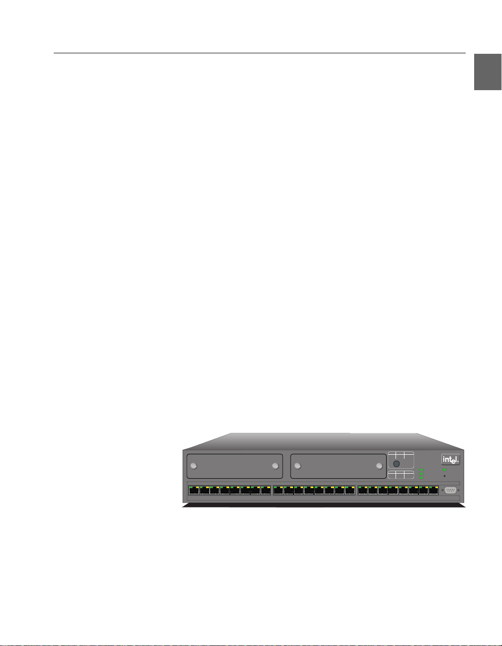
Introduction The LEDs on the front panel show the status of the ports, so you
should position the switch with the front panel facing you. You can
also see which ports the cables are connected to on the switch.
View of the front panel The front panel of the switch is shown below:
Slot BSlotA
123 87654 9 10 11 1615141312 17 18 19 2423222120
LEDs Green Orange
Off 10 Mbps Half duplex
Solid 100Mbps Fullduplex
PortStatus
LEDs Green Orange
Solid Link Disable
Blink Activity Collision
Intel Express
510T Switch
Status
Temperature
RPS
Power
Reset
Console
9600-8-N-1
1589
3
Page 14

C H A P T E R 1 Intel Express 510T Switch
Front panel ports
These ports are on the front panel:
Port Function
CONSOLE port
(DB-9)
Connects a PC (running a VT100 emulation), a VT100 terminal or a modem to
access the built-in Local Management program.
24 x 10/100BaseTX ports (RJ-45)
Connects devices using Unshielded Twisted
Pair (UTP) cabling complyi ng to EIA568A
Category 5 or ISO/IEC 11801 Category 5
level D.
Slots for modules After removing one or both of the cover plates, the modules can be
inserted to expand the functionality of the switch.
Front panel LED functions The LEDs on the front panel have the following functions:
LED
Port LEDs -
Shows the status for...
The operation of each port.
Green and Orange
Status The operation of the switch.
Power The internal power supply.
Temperature The internal temperature.
RPS (redundant
The external, redundant power supply.
power supply)
Buttons The buttons on the front panel have the following functions:
Button name Function
Port Status Shows the operational status of each port.
Reset Reset or enter Maintenance Mode or Recov-
ery Mode
4
Page 15

C H A P T E R 1 Intel Express 510T Switch
Rear Panel
Introduction The rear panel has a cooling fan outl et and the mai n supply cable, so
you should position the switch with the rear panel faci ng away fro m
you.
View of rear panel The rear panel of the switch is shown below:
Input
100-120VAC/2A
200-240VAC/1A
47Hz-63Hz
RedundantPower Supply(RPS)
1741
Rear panel parts The switch’s rear panel has the following parts:
Part Function
Fan outlet Cools the internal circuitry of the switch.
Power connection A socket to connect the power cord to the
main supply.
Redundant power
supply connector
Connects an external redundant power supply. If the internal power supply fails, the
redundant power supply starts immediately.
Installation
Important You must adhere to all local and national regulations governing the
installation and connection of electrical devices when installing the
switch.
5
Page 16

C H A P T E R 1 Intel Express 510T Switch
Before Installation
Contents of the pack Unpack the switch carefully and check that these parts are present:
Item Present?
One Intel Express 510T Switch
One power cord (suitable for your
power outlet)
One mounting kit
One CD-ROM
One Console cable
One Quick Start
One User Guide (you are reading it)
Late-breaking News
Intel Support Service papers
Check the package
contents
If you have not received all of the parts, or any of the parts are damaged, contact your dealer immediately.
Keep all the packaging materials in case you need to repack the
switch.
Check all labels Read all labels and rating pl ates on the switch. If there is anyth ing that
you do not understand , or if any of the in formation provided does not
appear to comply with your local or national rules and regulations,
consult your dealer before proceeding with the installation.
Essential reading It is important that you read the following:
• “Late-breaking News”.
This contains essential infor matio n you shoul d be aware of when
installing and using the product; for example, limitations and
compatibility issues.
• Warnings and the instructions earlier in this guide.
• The README.TXT file on the CD-ROM. This gives a general
description of the software and specific requirements.
6
Page 17

C H A P T E R 1 Intel Express 510T Switch
Positioning and Installing the Switch
Allow adequate ventilation The switch contains two fans to air-cool the internal circuitry. The air
is drawn in from the left of the unit and expelled through the outlet
grills on the right side and the rear.
To ensure correct airflow, leave 100 mm (4 inches) free spac e on both
sides and behind the switch. Do not allow the int ake or outlet grills to
become blocked.
On a desktop To install the switch in a desktop environment:
1 Find the four rubber feet in the pack that contains the rack
mounting kit.
2 Remove the backing strip from each of the four feet.
3 Attach the four rubber feet to the underside of the switch (to
ensure that the switch stands firmly).
4 Place the switch on a stable, flat surface.
5 Ensure that the air intake (on the left) and fan outlets (on the
right side and rear) ar e not block ed.
Warning The switch’s lifetime and operation al reliability can
be seriously degraded by inadequate cooling.
Rack requirements Install the switch in a standard rack in accordance with IEC297 (or
similar); if the mini mum outside mea surement s of the rack are 600 x
600mm (23.5 x 23.5inches), you must a llow 190mm (7.5 inches) of
space at the rear.
Mounting kit The switch is delivered with a kit to attach it to a standard 19-inch
equipment rack (with side suppor t rails). The kit con tains two mounting brackets and four screws (for attaching the brackets to the sides
of the switch).
Tools required for
positioning in a rack
In addition to the mounting kit, you need the following items to
mount the switch in a rack:
• Standard 19-inch rack with side support rails.
• 3 mm screwdriver.
7
Page 18
C H A P T E R 1 Intel Express 510T Switch
• Custome r-supp lied screws for securing the switch in the rack.
Mounting screws are not provided because the required sizes
may vary from rack to rack.
In an equipment rack To mount the switch in a standard equipment rack:
1 Attach the moun ting brack et marked “Left” t o the le ft-hand side
of the switch, and attach the mounting bracket marked “Right”
to the right-hand side of the switch, using the four screws provided.
B
t
lo
A
t
lo
S
0
1
9
8
7
6
5
4
3
2
1
S
81
71
1
6
1
5
1
4
1
3
1
2
1
11
Make sure that you attach the mounting brackets to the correct
sides. Otherwise the switch will not align correctly in the
equipment rack.
e
g
n
a
r
O
n
e
e
r
G
s
D
E
L
x
e
l
p
u
d
f
l
a
H
s
p
b
M
0
1
f
f
O
x
e
l
p
u
d
l
l
u
F
s
p
b
M
0
0
1
d
i
l
o
Intel Express
S
510T Switch
s
u
t
ta
S
t
r
o
P
e
g
n
a
r
O
n
e
e
r
G
s
D
E
L
e
l
b
a
s
i
D
k
n
i
L
d
i
l
o
S
o
i
s
i
l
l
o
C
y
t
i
v
i
t
c
A
k
n
i
l
B
1
2
0
2
9
r
e
w
o
P
s
tu
Sta
re
tu
ra
e
p
m
Te
t
e
s
e
R
n
S
P
R
e
l
o
s
n
o
C
4
2
3
2
2
2
1
-
N
-
8
-
0
0
6
9
1590
2 If the four rubber feet prevent the switch from standing firmly
on the equipment rack’s side support rails, remove them.
3 Set the switch in the equipment rack, and mak e sure there is
adequate space for air flow around the switch (see “Allow adequate ventilation” in “Posit io ni ng and Inst all i ng t he Swit ch” , p.
7).
4 Screw the mounting brackets securely to the equipment rack.
Ambient temperature If the switch is installed in a closed or multi-rack assembly, the oper-
ating ambient temperature of the rack environment may be greater
than the ambient temperature of the room. Make sure that the temperature of the rack environment does not exceed the recommended operating temperature for the switch.
8
Page 19

C H A P T E R 1 Intel Express 510T Switch
Installing a Module
Introduction You can increase the connectivity op tions of your switch by installing
a module.
Warning Modules are not designed to be installed in, or removed
from, the switch while it is in operation. You must
power off the switch before attempting to install or
remove a module.
Static-free working area The module’s printed circuit b oard is an Electrostatic Sensitive De-
vice and should be handled only in a static-free working area; otherwise, the printed circuit board may fail or be degraded.
Avoiding damage to the
circuit board
If you remove the plate covering the slot on the front of the switch,
for example, to install or remove a module, follow this procedure to
avoid damage to your printed circuit board:
Warning Do not remove the plate unless the switch is discon-
nected from the main power supply.
1 Disconnect the switch from the main p ower supply.
2 Ground the switch before you handle the printed circuit board.
3 Connect yourself to a non-painted/non-isolated part of the
grounded switch (for example the back panel) using a wrist
strap with 1MΩ resistance to ensure that you carry the same
electrostatic charge as the enclosure.
4 Remove the plate covering the slot.
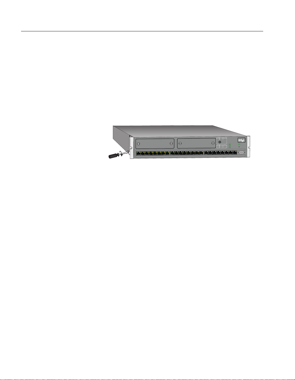
Installing a module To install a module:
1 If the switch is alread y oper at i onal , di sconn ect it from th e main
power supply.
2 Follow the instructions in “Avoiding damage to the circuit
board” above.
3 Unscrew the screws of t he plat e cove ring t he sl ot on the f ront o f
the switch. Save these screws and plate.
4 Insert the module into the slot (following the instructions in the
module’s User Guide). Place your thumbs just beneath the
screws on the front panel of the module and push in the module.
Secure it using the retaining screws.
9
Page 20

C H A P T E R 1 Intel Express 510T Switch
Removing the module
To remove a module:
1 If the switch is already operational, disconnect it from the main
power supply.
2 Follow the instructions in “Avoiding damage to the circuit
board” above.
3 Unscrew the screws securing the module.
4 Pull the module gently to disengage the connec tors fully from
the socket on the motherboard. Slide the module out completely.
5 Cover the empty module port with the plate and secure using
the screws.
Connecting Other Devices
Introduction Incorrect cabling is often the cause of network configuration prob-
lems
Use shielded cables Shielded cables nor mally comply with EM C and FCC emission lim-
its.
Only use unshielded cables when it is explicitly specifie d in the in-
stallation manual of the device in question.
Cables for the LAN Ports Ports on the switch are wired MDI-X, so use the following cable:
If you connect the switch to a... Then use a...
Workstation or server Straight-through cable 1:1
Device with MDI-X ports (for exam-
Crossover cable
ple another Intel switch or hub)
Device with MDI ports Strai ght-through cable 1 :1
10
Page 21

C H A P T E R 1 Intel Express 510T Switch
RJ-45 connector pin
assignments
Connecting a de vice to the
RJ-45 ports
The RJ-45 ports on the front of the switch have the following pin assignments:
Pin number Function
1RX+
2RX3TX+
6TX-
To connect a workstation compatible with IEEE 802.3 (Ethernet Version 1.0 and 2.0) or a fast access device (such as a server) to the
switch’s RJ-45 ports using UTP cable (Category 5):
1 Make sure that the device has a 100Mbps (100Base-FX or 10/
100Base-TX) network interface card installed.
If not, use your network interface card’s documentation to
install and configure it correctly.
2 If your workstation i s fitted with an RJ-45 interface then t here is
no problem. However, it is possible to atta ch t o ot her con nect or
types using an appropriate adapter. For example, use a UTP/
10Base-FL adapter for fiber connections
3 Connect one end of the UTP cable to an RJ-45 port on the
switch.
According to IEEE 802.3, the cable leng th must not excee d 100
meters (approximately 325 feet).
4 Connect the other end to the 100Base-TX connection on the
device.
Connecting the
management PC
To manage the switch from a PC connected d irectly to the switch , the
PC must not use frame tagging. To manage the switch from a PC with
IEEE 802.1Q tagged frames, management must be through a device
which untags the frame s.
Cable for the C on sol e Port If you connect a PC (via the Con sole Port), then use a null-modem ca-
ble.
11
Page 22

C H A P T E R 1 Intel Express 510T Switch
Connecting the Power
Introduction After connecting the devi ces to the switch, con nect th e power cabl e.
There are certain practical and safety considerations to be made before powering the switch on.
The Power Cable
Ground warning The switch is delivered with a power cable that fits the power sockets
in your country. If this is not the case, co ntact your dealer immediately and ask for the correct power cable.
Power cable wiring color
code
The wires in the power cable provided are color coded:
Color Connection
Green and yellow Ground
Blue Neutral
Brown Live
Important for UK use If the colors of the wires in the power cable provided do not corre-
spond with the markings that identify the term inals in your plug:
1 Make sure that the green and yellow wire is connected to the
terminal marked with the letter E, or with the ground symbol
, or is colored green and yellow.
2 Make sure that the blue wire is connected to the terminal
marked with the letter N or colored black.
3 Make sure that the brown wire is connected to the terminal
marked with the lette r L or colored red.
Power supply to a rack If the switch is installed in a rack, make sure the rack’s power supply
socket has a ground connection and t he rack is connected t o a branch
supply or a power supply socket with a ground connection.
12
To avoid overloading the circuit and damaging the wiring of t he power supply, the power su pply to t he rack must be adequate to cover the
extra power consumed by the switch.
Page 23

C H A P T E R 1 Intel Express 510T Switch
Power up
Powering up the switch Follow these steps to power up the switch:
1 Push the female end of the p ower cabl e int o the ma in socket (i n
the rear panel); pl ug the other end into the power supply outle t.
2 Make sure that the Power LED (on the front pa nel) is green.
If it isn’t green, make sure that the power outlet is working correctly (switched on). If the power outlet is on and the Power
LED is not green, then there is a fault within the switch and
you must contact your dealer.
3 Verify that an LED is lit for each of the front panel ports where
a powered on device is connected.
Start-up procedure Immediately after power-up, the following should happen during
start-up:
Stage STATUS LED... Then the switch...
1 Is red Is starting up
2 Turns to steady green Has started successfully
If the Status LED remains red, then the switch has not started successfully . T ry to rest art it; if the switch doe s not start, contact your dealer.
Look at the other front panel LEDs during start-up and check that
they are operating correctly.
Port LED states The LEDs reflect the state of each port:
LED Indicates
No lights Port enabled, no link.
Green, blinking
randomly
Port enabled, RX/TX traffic, link pulse
active.
Green, solid Port enabled, link pulse active.
13
Page 24

C H A P T E R 1 Intel Express 510T Switch
LED Indicates
Default settin gs afte r st artup
Green and Orange both
blinking randomly
Collision detected (with half duplex).
Port enabled, link pulse active.
Orange, solid Port disabled by management.
Green and Orange both
solid
Port disa bled by a hardware fault, or no
hardware connected.
Once the switch has started successfully, installation is complete and
the switch is using its default setting (al so known as defau lt conf i guration):
• All ports are enabled.
• All ports operate in auto-negotiation mode.
• Spanning Tree is disabled on all ports.
• Addresses that have been silent for more than 15 minutes are
purged from the swit ch’s address table (the MAC Address Aging
time).
• No access restrictions to Local Management (Telnet).
• No SNMP restrictions.
• No permanent MAC address entries defined. A permanent entry
is a MAC address that is defined as being permitted only on a
certain port. This can be a useful security feature.
• All ports are in the same VLAN (named <System>) and VLAN
mode (Stand-alone mode). VLANs allow you to create virtual
networks using specific switch ports, IP addresses, IP subnets
and MAC addresses.
• Flow Control is enabled on all ports.
• The connection with Local Management is timed-out after 10
minutes if there has been no input during this period.
After start-up This default configur ation is adequa te for simple workgroup environ-
ments to operate in basic switching mode.
Although the switch continues to operate without problems, we rec-
ommend that you change certai n parameters to suit your own requirements.
14
Page 25

C H A P T E R 1 Intel Express 510T Switch
Follow the instructions in Chapter 2 to change the configuration
while the switch is operating.
Other LEDs on the front panel
Introduction There are three other LEDs and one button on the front panel that
show how the switch is operating:
• Status LED
• Temperature LED
• Redundant Power Supply (RPS) LED
• Port Status button
LED colors and their
meanings
The LEDs give information about the state of the switch:
LED Color Meaning
Status Gre en Solid: The switch is operating normally.
Blinking (1 Hz): Updating software or
running in recovery mode.
Blinking (5 Hz): Running in maintenance mode.
Red The switch is resetting, or either hard-
ware or software errors are detected.
Temperature G reen Normal operating temperature.
Orange Temperature is higher than normal.
Check that the area around the air intakes
and vents are clear of obstructions.
Red Temperature is too high and the switch
will shut down.
RPS Green Off: No RPS connected.
Solid: RPS connected, but not needed.
Orange Normal power supply has failed and the
RPS has taken over.
15
Page 26

C H A P T E R 1 Intel Express 510T Switch
Port Status button
To see the speed and duplex setting s of all t he ports, press t he Port
Status
button. The function of the por t LEDs chang es fo r a period
of 5 seconds, where they have the following meaning:
LED Color Meaning
Left (Speed) Green Off: 10Mbps
Solid: 100Mbps
Right
(Duplex)
Orange Off: Half duplex
Solid: Full duplex
16
Page 27

2
In this chapter This chapter covers the following topics.
Intel Device View
Topic See Page
System Requirements 18
Installation and Removal 19
Using Intel Device View 20
Installing and Managing Switches 26
Device Tree 29
Device View (Main Display) 31
Explorer 36
Diagnostics Window 37
Trap Window 38
System Window 39
Errors Window 39
17
Page 28

C H A P T E R 2 Intel Device View
System Requirements
Requirements for Inte l
Device View under
Windows
You need a PC with the following minimum requirements to run Intel
Device View:
• Microsoft Windows NT workstation or server, version 4.0, or
Microsoft Windows 95 or Microsoft Windows 98.
(Windows NT 4.0 English language version workstation recommended.)
• A network adapter installed.
• 30 MB of free hard disk space.
• A color display with 800 x 600 resolution and 256 colors.
• The Microsoft IP protocol must be installed and configured
before installation o f Intel Device View.
DHCP limitation Three important things to know:
• Do not use a PC running Windows NT server (with its DHCP
server installed) to run Intel Device View.
• Ensure the IP address for the PC is not changed by the DHCP
server.
• PCs that use a network management system that uses BootP,
DHCP or SNMP Trap Receiving, may have their network management system disabled by Intel Device View.
Management PC
restrictions
Requirements for Inte l
Device View on the Web
server
18
To manage the switch from a PC connected d irectly to the switch , the
PC must not use frame tagging. To manage the switch from a PC with
IEEE 802.1Q tagged frames, management must be through a device
which untags the frames.
You need a PC with the following minimum requirements to run Intel
Device View:
• One of the following running: Microsoft Windows NT 4.0 Server
with Internet Information Server (IIS) 2.0 or later; or Windows
NT Workstation with Peer Web Services.
• 30 MB of free hard disk space.
• The Microsoft IP protocol must be installed and configured
before installation o f Intel Device View.
Page 29

C H A P T E R 2 Intel Device View
Web server restrictions
Requirements for Inte l
Device View on the Web
client
Requirements for Inte l
Device View with plugin
To start the installation of
Intel Device View
To manage the switch from a web server connected directly to the
switch, the web server must not use frame tagging. To manage the
switch from a web server with IEEE 802.1Q tagged frames, management must be through a device which untags the frames.
To run Intel Device View, the client requires:
• Microsoft Internet Explorer (4.00) running on Windows 95 or
Windows 98 or Windows NT 4.0.
• A color display with a minimum of 800 x 600 resolutio n a nd 256
colors.
To run Intel Device View with a plugin, the PC must be runni ng HP
OpenView* or Intel LANDesk Manager.
Installation and Removal
Normally, the Setup program for Intel Device View will start automatically after you insert the compact disc (CD) in your CD ROM
drive. However, if it does not, use th e standard W indows proce dures
for installing programs. A screen similar to the one below is displayed:
19
Page 30
C H A P T E R 2 Intel Device View
T o install Inte l Device Vie w
for Windows
Click Install Windows and follow the on-screen instructions.
When the installation is com plete, Intel Device View will start auto-
matically when “Launch Intel Device View” is selected.
T o install Inte l Device Vie w
for Web
Click Install Web and follow the on-screen instructions. When
the installation is complete, Intel Device View will start automatically when “Launch Intel Device View ” is selected.
T o install Inte l Device Vie w
when using HP
OpenView* or Intel
LANDesk
®
Manager
Click Install Plugin and follow the on-screen instructions.
When the installation is complete, Intel Device View starts automat-
ically when “Launch Intel Device View” is selected.
Removal of Intel Device View
Removal under Windows To remove Intel Device View under Windows:
1 Close all Intel Device View programs.
2 Use standard Windows procedures to uninstall Intel Device
View.
Using Intel Device View
Concept Intel Device View configures all the parameters on your switch, or
group of switches known from here on as a stack, (via SNMP) and
monitors their activities.
20
Page 31

C H A P T E R 2 Intel Device View
Navigating through Intel
Device View
Many commands are available from within Intel Device View. These
are best accessed using mouse actio ns. However, Windows users can
also access most of them through the menu bar.
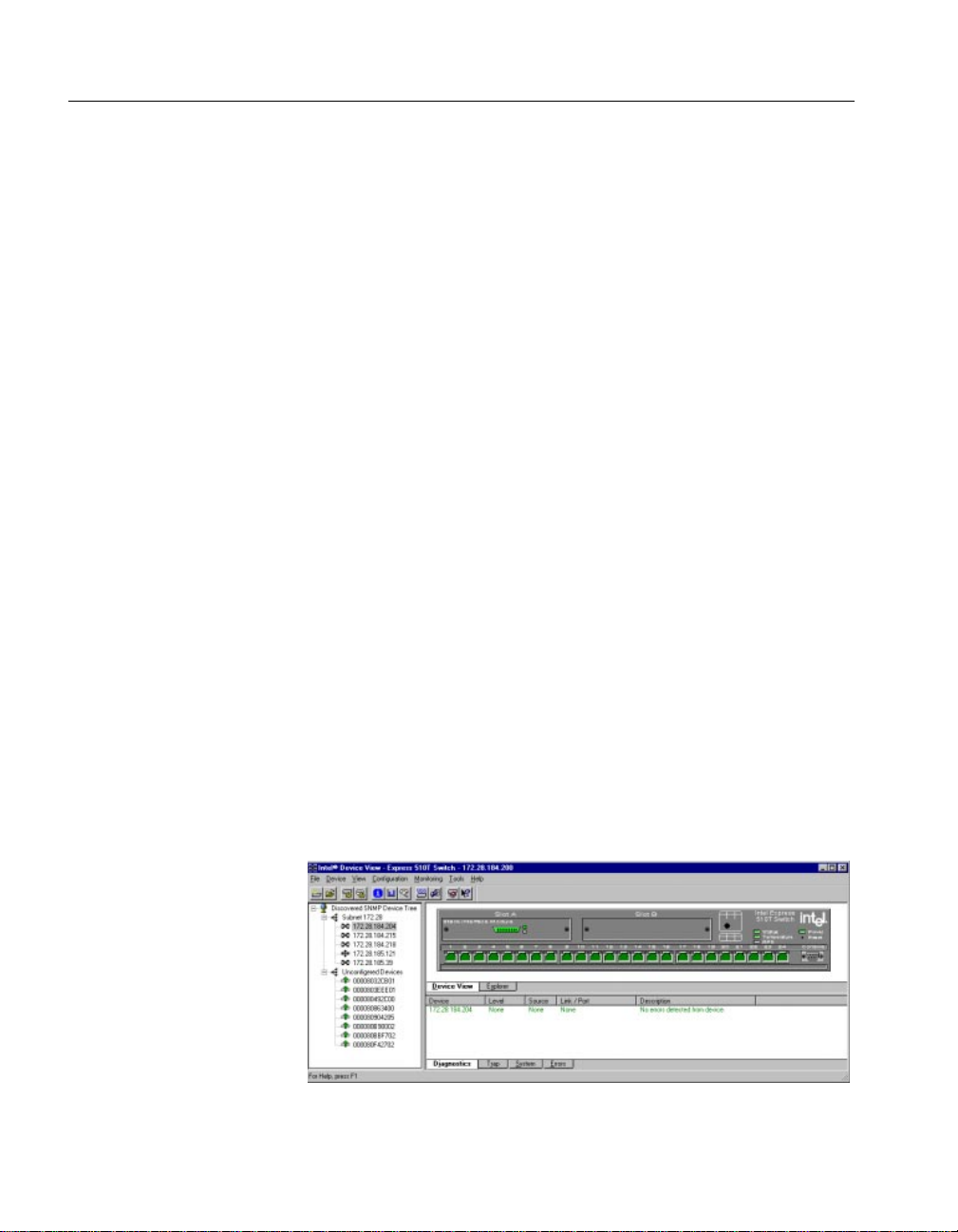
The Intel Device View
window
There are three sections:
• Device Tree — displays the separate branches on your LAN,
including a branch showing all unconfigured devices.
• Interactive picture of the switch, or stack — shows the port state
or the Explorer, which provides port and VLAN details for the
switch or stack.
• Information section — provides details about diagnostics, traps,
errors and the system. Using this window, you can show activity
statistics for the switch (or the stack) and for individual ports.
Before a switch is contacted
Basic menu bar
commands
File menu This contains one command, Exit which en ables you to exit the In tel
Before a switch or stack is contacted, the following commands are
available through the menu bar. The toolbar buttons are for users using Intel Device View in Windows.
Device View. When a switch or stack is open and the configuration
has been changed and not saved to the Flash Memory as the permanent configuration , you are asked if you want to save the ne w confi guration before exiting.
Device menu The Device menu contains the following switch commands:
• Install — enables you to install a new device, which does not
have an IP address, in Intel Device View. Can also be accessed
by selecting .
• Manage — enables a switch or stack that has an IP address
already assigned to be managed or configured. Can also be
accessed by selecting .
• Discover — enables you to set up how the Device T ree d iscovers
devices and users.
Note: do not leave the Subnet Mask blank or set to 0.0.0.0, as
Intel Device View will continually broadcast device discovery
messages to all networks and use bandwidth.
21
Page 32

C H A P T E R 2 Intel Device View
• A list of IP addresses — contains the last eight switches success-
fully contacted from Intel Device View. These can be used to
manage the switch.
View menu — for
Windows users only
The View menu allows you to customize the Intel Device View display to your own preferences: the Toolbar and Status Bar can be
switched on and off.
Monitoring menu This menu gives access to set the Default P references for Intel Device
View, see “Setting the Preferences”, p. 24.
Tools menu The Tools menu has the following commands:
• Ping — sends ICMP echo packets to the switch. Can also be
accessed by selecting .
• A Report Manager — uploads reports, logs and the parameter
block from the switch. Can also be accessed by selecting .
• A Recovery Manager — regains control of your switch if you
have lost contact. This is described in “Recovery Manager”, p.
94.
• A DNS-IP conversion tool converts DNS names to IP addresses.
These are described in detail, together with switch specific tools, in
the Chapter “Managing the Switch”, p. 71.
Help menu The Help menu has the following commands for the switch:
• Help for Intel Device View. Can also be accessed by selecting the
Help icon then clicking on the feature of interest
22
• Help for switch specific topics.
Page 33

C H A P T E R 2 Intel Device View
After a Switch or Stack is Contacted
Commands When Intel Device View contacts a switch, the basic commands are
supplemented with:
• Local Management access — provides Telnet access to monitor-
ing functions embedded in the switch.
• RMON facility — gathers information about the network traffic,
monitors traffic on subnets and enables you to define alarms on
the individual ports.
• Stack Synchronization Manager (for stacks only) — enables you
to establish a stack from a group of switches connected via a
Matrix Module, or add a swi t ch t o an existing stack and t hen synchronize their configurations.
• Switch Position Organizer (for stacks only) — enables you to
move the switches displayed on screen around in the stack.
• Color Code Matrix Ports (for stacks only) — colors the individ-
ual ports on the Matrix Module. This simplifies the task of tracing cables, as the ports on the Stack Interface Modules become
the same color as the corresponding Matrix Module port.
• A color coding chart for Intel Device View to show the states of
switch’s LEDs
23
Page 34

C H A P T E R 2 Intel Device View
Setting the Preferences
Setting the polling
intervals
The polling intervals determi ne how often Intel Device View contacts
the switch or stack and updates the status and information displayed.
To change the polling parameters:
1 Select Monitoring>Preferences.
2 Click Polling or Monitor.
3 If you want the polling to happen more frequently than just on
opening, click
4 Move the Interval slider to the required time.
5 Click OK.
Periodically.
24
Page 35

C H A P T E R 2 Intel Device View
Setting the timeout
parameters for SNMP
Setting the community for
SNMP polling
The timeout determines the intervals between polling and the number
of times the request is retri ed if a devi ce is not respo nding. To c hange
the timeout paramet ers:
1 Select Monitoring>Preferences.
2 Click Timeouts.
3 Change the values.
4 Click OK.
The community for SNMP polling determines access rights. To
change the community:
1 Select Monitoring>Preferences.
2 Click Community.
3 Type the new community name.
4 Click OK.
25
Page 36

C H A P T E R 2 Intel Device View
Installing and Managing
Switches
Following installation of
Intel Device View
Adding new switc hes To add new switches (that have not been assigned an IP address) to
The Install Wizard The Install Wizard requires that you enter a minimum amount of in-
After installing Intel Device View, you can add new switches, establish or expand stacks of switches, and manage existing switches and
stacks.
Intel Device View, select
will start and guide you through the installation.
formation to set up t he switch for mana gement by Intel Dev ice View.
To select the c orrect new device, you n eed to know the dev ice’s MAC
address. You can find this on a label on the rear panel of the device.
You must assign an IP address (and subnet mask) to the switch on
your Local Area Network (LAN).
Device>Install. The Install Wizard
26
Intel Device View uses this address for configuration and management purposes.
Page 37

C H A P T E R 2 Intel Device View
Matrix Module connected
to a new switch
When the Install wizard detects that a new switch is connected to a
Matrix Module, a message info rms that you must decide how to manage the switch.
If you want to manage it separately, the installation is completed and
the switch is displayed in th e Intel Device View window. If you want
to manage it as part of a st ack, you have the op portunity to assign consecutive IP addresses in the next dialog.
Managing an existing
switch or stack
The Synchronization Wizard completes the installation. The complete stack, including the new switch, then appears i n the Intel Device
View window. The Synchronization wizard is described in detail in
“Stack Synchronization Manager”, p. 95.
To manage a switch or stack that has an IP address al ready assigned:
1 Select Device>Manage The Manage dialog box appears.
2 Type in the switch’s IP Address or MAC address.
27
Page 38

C H A P T E R 2 Intel Device View
3 Select the box if you want to open the switch in a new Intel
Device View window.
4 Click OK.
Establishing and
expanding a stack
If you connect switches that already have IP addresses assigned together via a Matrix Module, you can ma nage them as a st ack. To cr eate or expand an existing stack:
1 Select Device>Manage, and the Manage dialog opens.
2 Type in the IP Address or MAC address of one of the switches.
All the switches connected via the Matrix Module are displayed
in this window, even switches that are already configured as a
stack.
28
3 If the switches don’t have compatible software, the Upgrade
box is checked. If one or more of the switches aren’t configured, the Configure IP address box is check.
4 Select Stack Management.
5 Select OK. The Upgrade Wizard starts automatically if software
needs to be upgraded.
Page 39

C H A P T E R 2 Intel Device View
Device Tree
Introduction The Device Tree displays the separate subnets on your LAN as
branches in a tree. This includes a branch that shows all the unconfigured devices on the LAN.
Identifying devices The Device Tree uses several icons to repres ent the indivi dual devic-
es:
Icons Device Description
Recognized as a switch.
Recognized as a router.
Recognized as a hub.
Device contacted, but not recognized.
Lost contact with device.
29
Page 40

C H A P T E R 2 Intel Device View
Installing and managing
switches
Right mouse button
commands
Double clicking the switch’s IP address or MAC address opens existing switches in the Intel De vice View window, or starts the Install
Wizard for new switches.
By positioning the mouse pointer in the Devi ce Tree and clicki ng the
right mouse button, the following functions are available:
Functions Description
(without a device selected)
View
IP Address Sorts the devices by their IP addresses.
Name Sorts the devices by their DNS names.
Add Device If a device has not been auto-detected
then you can add it to the tree. You need
to know its IP address.
Find Locates a specific device by searching for
its IP address.
Refresh Polls the network a nd redisplays the tree.
If a new device has been connected, it
will appear after a refresh.
30
(additional functions with a device selected)
Launch With Opens the switch in Intel Device View.
Delete Removes a device from the Device Tree.
Edit Change the name, community setting s
(read and write) and polling rate of the
device.
RMON
Statistics Provides subnet management statistics.
History Lists monitored traffic on a subnet.
Alarms Enables activity alarms to be set.
Logs Sets events defined by Log, Trap or Log
and Trap.
Page 41

C H A P T E R 2 Intel Device View
Device View (Main Display)
Switch contacted When Intel Device View c ontacts the switch or stack, the front (inter-
face side) of the switch or stack is displayed.
This view provides a real-time view of t he switch, or st ack and ports ,
which behave in the same way as the physical switch. For example,
the LEDs change color accordi ng to the state o f the switch/stack. You
can fully manage the switch or stack using this display.
Mouse moves Using a mouse makes it easier to operat e Intel Device View and saves
you time:
Mouse action Information
Right-click switch Shows the sw itch-related menus for
configuration and monitoring.
Right-click stack border Shows the stack-related menus for
configuration and monitoring.
Right-click a port Shows the port-related menus for
configuration and monitoring.
Double left-click switch Opens the Device Setup menu.
Double left-click a port Opens that port’s Setup menu.
31
Page 42

C H A P T E R 2 Intel Device View
Right mouse button
commands for a sing le
switch
Right click a single switch and Intel Device View offers:
Functions Description
Device Setup Displays comprehensive information
about the switch’s overall setup.
VLAN Setup Provides an overview of existing VLANs
and the opportunity to add new ones or
change existing ones.
Device Information Informs you about the type of switch, its
location, who is responsible for it and the
amount of time passed since the switch
was restarted.
Port Overview Gives detailed monitoring information for
each port.
Device Activity Displays, in a graph format, information
about the activity on the ports.
VLAN Displays monitoring information and the
status of the VLAN links.
Device Reboots the switch and provides informa-
tion about the firmware in the switch. Also
enables the switch’s firmware to be
upgraded.
32
Configuration Ensures the switch’s configuration is safe
by saving it to the flash memory, by backing up to disk and by being able to restore
it again should it be lost. If ne cessary, the
switch can be returned to the factory
default configuration.
Monitoring Provides comprehensive details for Span-
ning Tree statistics and RMON facilities,
as well as Hardware information and an
Access Overview.
Page 43

C H A P T E R 2 Intel Device View
Right mouse button
commands for a stack
border
When managing a stack of switches, right cl ick the stack bo r der and
Intel Device View offers:
Functions Description
Stack Setup Dis plays comprehensive information
about the switch’s overall setup.
VLAN/Routing Setup Provides an overvi ew of existing VLANs
and the opportunity to add new ones or
change existing ones.
IP Filtering Setup Defines user groups and filters the packets
sent to them.
Stack Health Monitor Provi de s the IP addresses for all the
switches in the stack, the type of switch
and whether they are responding to ping.
IntraStack Traffic Gives information about the traffic
through the Matrix Module.
System Information Gives the name and location of the stack,
together with a contact name and the
length of time the stack has been running.
Stack Activity Displays as graphs monitoring information
of traffic on the ports in the stack.
Port Overview Provides port performance, packet distri-
bution and spanning tree informati on for
all the ports in the stack.
Device Enables you to reboot the stack and pro-
vides information about the firmware in
the switches.
33
Page 44

C H A P T E R 2 Intel Device View
Functions Description
Configuration Ensures the stack’s configuration is safe
Monitoring Provides Hardware information about the
Tools Gives access to the Synchronization Man-
by saving it to the flash memory, by backing up to disk and by being able to restore
it again should it be lost. If ne cessary, the
stack can be returned to the factory default
configuration.
separate switches in the stacks and the
access rights to the devices on the LAN.
age, the Switch Position Organizer and
Color Code Matrix Ports function.
Right mouse button
commands for a switch in
a stack
When managing a stack of swit ches, right click a switch and Intel Device View offers:
Functions Description
IP and Name Setup Displays the switch’s IP address and Sub-
net mask.
Device Activity Displays, in a graph format, information
about the activity on the ports in the switch
selected.
Spanning Tree Provides statistics about the Spanning
Tree on the selected switch.
VLAN Displays monitoring information and the
status of the VLAN links.
Device Restarts the switch and provides informa-
tion about the firmware in the switch.
Configuration Ensures the switch’s configuration is safe
by saving it to the flash memory.
Monitoring Displays, as a graph, the activity on all the
ports in the switch and RMON facilities.
34
Page 45

C H A P T E R 2 Intel Device View
Right mouse button
commands for a port
Right click a single port and Intel Device View offers:
Functions Description
Port Setup Displays the port status, the speed and
duplex settings, and spa nni ng tr ee sett i ngs.
Add Port to VLAN Adds the port to a VLAN.
Port Details Displays comprehensive performance, dis-
tribution and spanning tree details.
Port Activity Displays, as a graph, the activity on the
port.
VLAN Port Monitor-
ing
Provides details about the MAC and IP
addresses on the VLANs.
RMON Statistics Provides RMON statistics for the selected
port.
Color coding The switch and ports are displayed in different colors:
Color Means
Switch
Body
Gray The switch is operational (the soft-
ware is loaded and running) and it
can be contacted by Intel Device
View via the network.
Dark blue That switch is selected, and various
device-specific parameters can be
changed using the right-mouse button.
35
Page 46

C H A P T E R 2 Intel Device View
Ports Dark green Port enabled, but no plug connected.
Stack border Dark blue The stack is selected, and various
Color Means
Light green Port enabled and plug connected.
Brown Port disabled by management or a
hardware error.
Dark blue That port is selected, and various
port-specific parameters can be
changed using the right-mouse button.
Purple Port mirroring is enabled here.
stack-specific parameters can be
changed using the right-mouse button.
Everything;
switches,
ports and
stack border
Light blue Intel Device View has lost contact
with the devices (for example, the
switch or your PC is disconnected
from the LAN).
Explorer
Intel Device View Explorer The Explorer within Intel Device View displays management infor-
mation, for example VLANs on this switch and other switches.
If a switch is disabled or not operational, it is displayed with a red
cross through it.
General management information for the switch is accessed from the
Monitoring menu.
36
Page 47

C H A P T E R 2 Intel Device View
Diagnostics Window
Intel Device View
Diagnostics
Right mouse button
commands
The Diagnostics window helps you troubleshoot the switch/stack to
get it working properly in case of problems.
The Diagnostics window lists any problems detected by the switch/
stack and notes the level o f the problem (fatal error, error or not e) and
the port on which the error occurred. Messages are automatically
cleared from the list when the problem no longer exists
Right click a message and Intel Device View offers:
Functions Description
Details Displays a diagnostic details window that
describes the problem and gives a po ssible
solution.
Refresh Reloads and updates all the diagnostic
information.
Clear Clears all the messages displayed.
Use Color Coding Displays the messages in different colors,
depending on their severity.
37
Page 48

C H A P T E R 2 Intel Device View
Diagnostic details window
This window provides comprehensive details of the error.
Trap Window
Traps window The Traps window displays all traps generated by the switch.
Color coding Traps are generated by the switch for many events, both normal and
errors. Traps displayed in Intel Device View are color coded according to the severity of the trap .
Right mouse button
commands
38
Right click a message and Intel Device View offers:
Functions Description
Refresh Reloads and updates all the informati on in
this window.
Clear Clears all the messages displayed.
Properties Enables color coding to be switched on
and off and define maximum number of
messages displayed.
Page 49

C H A P T E R 2 Intel Device View
System Window
System window The System window contains a log o f all the major switch e vents with
date and times (for example, return to factory default, filter entry settings, modules inserted in slots).
Right mouse button
commands
Right click a message and Intel Device View offers:
Functions Description
Refresh Reloads and updates all the informati on in
this window.
Clear Clears all the messages displayed.
Pause Pauses the normal updating of information
in this window.
Errors Window
Errors window The Errors window is a log of all error messages generated by the
switch.
39
Page 50

C H A P T E R 2 Intel Device View
Right mouse button
commands
Right click a message and Intel Device View offers:
Functions Description
Refresh Reloads and updates all the informati on in
this window.
Clear Clears all the messages displayed.
Pause Pauses the normal updating of information
in this window.
40
Page 51

Standard
3
In this chapter Configuration is the way we chan ge t he setup of the switch or stack.
Configuration
In this chapter you will find all the instructions you need to change
setups that affect the switch, or stack, and the ports.
Topic
Changing the Setup of the Switch or
Stack
Changing the Setup of the Port 57
In chapter 4 you will find instructions to integrate VLANs into your
setup.
See Page
42
41
Page 52

C H A P T E R 3 Standard Configuration
Changing the Setup of the
Switch or Stack
Improving switch security To restrict the use of the switch or stack, you can:
• Change the administrator password for local management.
• Change the user password for local management.
• Limit access to Local Management via the Console port and/or
Telnet.
• Specify a time of “no input”, after which the connection with
Local Management is terminated.
• Change the password for moving files with TFTP.
• Specify use of TFTP.
• Restrict access to include only the stations named on the Authen-
tications list.
Using the mouse There are two ways to access the Device Setup (for single switch-
Stack Setup window:
es) or
• Double-click the switch or the stack border.
• Right-click the switch or the stack border.
42
Page 53

C H A P T E R 3 Standard Configuration
System
Identifying the switch To assist with switch identification and administration, you can
change certain switch details (name, location and contact person).
With a switch or stack in the Device View window:
1 Select Device Setup or Stack Setup.
Click System.
2
3 Change the details.
4 Click OK.
These details are used by SNMP management centers.
43
Page 54

C H A P T E R 3 Standard Configuration
Internet Protocol
Changing IP details To change the main IP address and network mask:
1 Select Device Setup or Stack Setup.
2 Click IP.
3 Change the details.
44
4 Click OK.
This is used to contact the switch via IP (TFTP, S N MP, TELNET etc.) protocols.
Page 55

C H A P T E R 3 Standard Configuration
Local Time
Setting the date and clock
to local time
To change the clock in th e switch to your local time:
1 Select Device Setup or Stack Setup.
2 Click Date/Time.
3 Click Insert Current PC Date/Time to show the present
settings. If this is satisfact ory, click
OK.
Note The clock displays the time at which it is accessed
and not the current time.
4 If the time or the date is not satisfactory, click the date and/or
time options and type the new time and date.
5 Click OK.
Authentication
Purpose SNMP is a fully define d, i nt er ope ra ti ve standard that helps you man-
age both the switch and the network. To do this you can:
• Specify the names of the hosts to access the SNMP agent on the
switch (authentication) by defining the source IP and community
• Specify read-write or read-only for authenticated hosts
• Request a trap to be sent if authentication is violated
Note If no hosts are defined in the Authentication List, any host
can access the SNMP agent in the switch.
45
Page 56

C H A P T E R 3 Standard Configuration
Security
The authentications list defines the hosts that can carry out SNMP,
TFTP or Telnet management on the switch, have read-write or readonly rights and access to communities. You can:
• Add a new entry to the list
• Delete an entry
• Edit ex isting entries
Adding a device To add a host that is allowed to carry out management on th e switch:
1 Select Device Setup or Stack Setup.
2 Click Authentications.
46
3 Click Send trap when authentication violation.
A message will be sent to the
Traps window if unauthorized
hosts try to carry out management on the switch.
4 Click Add.
5 In IP address, type the IP address of the device to manage
the switch.
You can have a maximum of eight addresses in the list. The
address 0.0.0.0 indicates that all IP addresses are accepted.
6 Click Protocol and select one.
7 Click Rights and specify the level of access to the switch
8 For SNMP only, click Community and type the SNMP request
name accepted by the SNMP agent.
If no community name is specified, all community names are
accepted by the SNMP agent.
Page 57

C H A P T E R 3 Standard Configuration
9 Click OK.
Traps
Purpose A trap alerts you of events occurring in the switch. The traps list
shows where SNMP traps (generated by the switch) are sent. You
can:
• Add a new entry to the list
• Delete an entry
• Edit ex isting entries
Adding a trap Note If there are no entries in the Traps list, then no SNMP traps
are sent.
1 Select Device Setup or Stack Setup.
2 Click Traps.
3 Click Add.
4 Type the Destination IP address, or click This PC.
5 Type the community (SNMP password).
6 Click OK.
47
Page 58

C H A P T E R 3 Standard Configuration
Permanent Entries
Purpose Enables you to allocate a p ort to a device that d oes not send out device
information. These devices are not removed from the switch’s address table, regardless of how long they are quiet. This is useful for
connections to printers and other similar devices. You can:
• Add a new entry to the list
• Delete an entry
• Edit ex isting entries
Adding a P ermanent En try To add a device to the switch’s address table:
1 Select Device Setup or Stack Setup.
2 Click Permanent Entries.
48
3 Click Add.
4 Type the device’s MAC address.
5 Click Port number and select one. A permanent entry is
only made on the defined port.
6 Click OK.
Page 59

C H A P T E R 3 Standard Configuration
Link Aggregation
Purpose Combines two or four adjacent ports to increase the bandwidth be-
tween two switches or stacks. You can:
• Add a new entry to the list
• Delete an entry
Adding an Aggregate Link To set up and add an aggregate link:
1 Select Device Setup or Stack Setup.
2 Click Link Aggregation.
3 Click Add.
4 For a stack, click Switch and select one from the list.
5 Click Aggregation width: and select 2 Ports or 4
.
Ports
6 Click Anchor Port and select a port.
7 Type a unique name for the link.
8 Click OK. For further configuration of a link, for example in a
VLAN, use the Anchor Port.
49
Page 60

C H A P T E R 3 Standard Configuration
Port Mirroring
Purpose Provides a facility to debug or mo nitor traffic on a specific po rt, by
duplicating the tr affic and sen ding it to a specifie d port. Only one pair
of ports can be mirrored per switch. Within Port Mirroring, you can:
• Add a new entry to the list
• Delete an entry
• Edit ex isting entries
Adding Port Mirroring To add a mirrored port to a switch:
Note If Port Mirr oring is en abled, the source port will be in store-
and-forward mode. Therefore, Runt s, C RCs, et c. will not be
forwarded or mirrored.
1 Select Device Setup or Stack Setup.
2 Click Port Mirroring.
50
3 Click Add.
4 For a stack, click Switch and select one.
5 Click Reflect from and select the port that you want.
6 Click Reflect to and select the port to where the traffic can
be debugged/monitored.
7 Click OK.
Page 61
C H A P T E R 3 Standard Configuration
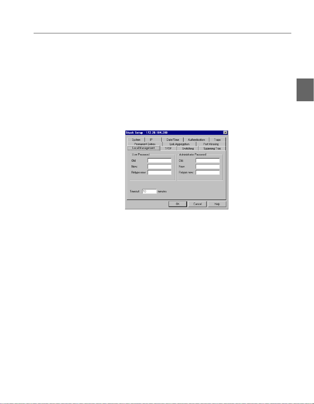
Local Management
Changing password
details
The administrator has read-write access at all levels. The user can
read the monitoring screens, but cannot change the configuration, update software or rese t th e stat ion. T o pre vent u nauthorized person nel
changing configurations:
1 Select Device Setup or Stack Setup.
2 Click Local Management.
3 You can change the passwords for the Administrator and User.
4 Type the old password.
5 Type the new password.
6 Retype the new password (in Retype new).
7 Click OK.
Changing timeout details When there has been no input during this period, the connection with
Local Management is terminated. To change the timeout interval:
1 Select Configuration>Device Setup.
2 Click Local Management.
3 Type the new time.
4 Click OK.
51
Page 62

C H A P T E R 3 Standard Configuration
TFTP
Changing password
details
Changing the MAC
address ageing time
To give added security, you can limit the number of staff authorized
to transfer TFTP files by chan ging the TFTP password. To change the
password:
1 Select Device Setup or Stack Setup.
2 Click TFTP.
3 Type the old password.
4 Type the new password.
5 Retype the new password (in Retype new).
6 Select OK.
Switching
To change the time a MAC address is kept in the filter before being
purged:
1 Select Device Setup or Stack Setup.
Click Switching.
2
52
3 Click MAC Address Ageing.
4 Type the required number of minutes.
5 Click OK.
Page 63

C H A P T E R 3 Standard Configuration
Changing the flow control
Changing the default
forwardi ng mod e
Enable forward learn
packets mode
Flow control prevents the loss of frames during busy periods. Note
that the individual port settings overrule the default setting. To
change the default flow mechanism on all ports:
1 Select Device Setup or Stack Setup.
2 Click Switching.
3 Click Default Flow Control.
4 Click Enabled or Disabled.
5 Click OK.
To change the forwarding mode to be used on all ports:
1 Select Device Setup or Stack Setup.
2 Click Switching.
3 Click Default Switch Forwarding Mode.
4 Click the default forwarding mode you want.
5 Click OK.
When this mode is enabled, all packets are forwarded. However, if
there is not enough memory in the switch, due to heavy load, the
packet is discarded. Wh en this mode is d isable d, only “IPX Get server” request packets are forwarded. To enable or disable this mode:
1 Select Device Setup or Stack Setup.
2 Click Switching.
3 Check the box to enable this mode.
4 Click OK.
53
Page 64

C H A P T E R 3 Standard Configuration
Adaptive Forwarding Mode
Purpose You can:
• Change the Sample Time
• Define the minimum and maximum errors acceptable before
changing the forwarding mode
Note While CRC errors and runts are the most likely parameters
to cause the switching mode to change, t hey are not t he only
ones.
Changing the time to
measure errors
Changing number of
errors before adaptive
forwarding mode operates
The sample time should be the shortest time needed to detect errors.
If the sample time is too great, there may be too many errors before
the forwarding mode changes. To change the t ime the switch ret ains
error counters:
1 Select Device Setup or Stack Setup.
2 Click Switching.
3 Click Advanced.
4 Click Sample Time.
5 Type the required number of seconds.
6 Click OK.
Adaptive forwarding ch anges the forw arding mode depend ing on the
upper and lower limits of specific erro r types. To change the number
of upper and lower limits:
54
1 Select Device Setup or Stack Setup.
2 Click Switching.
3 Click Advanced.
Page 65

C H A P T E R 3 Standard Configuration
4 Click the required parameter.
5 Type the percentage of errors or runts.
6 Click OK.
Spanning Tree
Purpose You can change the:
• Priority given to the switch
• Maximum length of time information is retained by the switch
• Time between transm itted Configuration BPDUs
• Time the switch spends in the Listening and Learning states
Warning when using
VLANs
Why change thes e from
their defaults?
It is important to be aware of problems that may arise when using
Spanning Tree and VLANs. The Spanning Tree can use alternative
paths (such as different ports) to get messages to their destination.
VLAN
A
SlotBSlotA
123 87654 9 10 11 1615141312 17 18 19 2423222120
SlotBSlotA
123 87654 9 10 11 1615141312 17 18 19 2423222120
A
VLAN
B
LEDs Green Orange
Off 10Mbps Halfduplex
Solid 100Mbps Fullduplex
IntelExpress
510TSwitch
PortStatus
Power
Status
LEDs Green Orange
Temperature
Solid Link Disable
Reset
Blink Activity Collision
RPS
Console
Switch 1
9600-8-N-1
LEDs Green Orange
Off 10Mbps Halfduplex
Solid 100Mbps Fullduplex
IntelExpress
510TSwitch
PortStatus
Power
Status
LEDs Green Orange
Temperature
Solid Link Disable
Reset
Blink Activity Collision
RPS
Console
9600-8-N-1
W
Y
Switch 2
B
STP
SlotBSlotA
123 87654910111615141312 17 18 19 2423222120
SlotBSlotA
123 87654910111615141312 17 18 19 2423222120
LEDs Green Orange
Off 10Mbps Halfduplex
Solid 100Mbps Fullduplex
IntelExpress
510TSwitch
PortStatus
Power
Status
LEDs Green Orange
Temperature
Solid Link Disable
Reset
Blink Activity Collision
RPS
Console
9600-8-N-1
X
Z
LEDs Green Orange
Off 10Mbps Halfduplex
Solid 100Mbps Fullduplex
IntelExpress
510TSwitch
PortStatus
Power
Status
LEDs Green Orange
Temperature
Solid Link Disable
Reset
Blink Activity Collision
RPS
Console
9600-8-N-1
1738
The diagram above, shows two switches. On th e left, we see th e tw o
switches connected and the ports are gr ou ped i n t wo VLANs: A and
B. On the right, we have enabled STP; ST P bl ocks t he pat h bet ween
X and Z (to avoid looping) and, therefore, dest roys t he VLAN setup
(because VLAN B needs these ports to receive messages).
The switch is delivered with Spanning Tree d efault values set to tho se
recommended by the IEEE 802.1 d standard. These values are conservative worst-case estimates for LANs consisting of a large number of
switches. Therefore, changing these default values may improve the
performance of you r network.
55
Page 66

C H A P T E R 3 Standard Configuration
Changing the spanning
tree priority
The higher the value, the lower the chance of the switch being used
as the root bridge. To change the priority value:
1 Select Device Setup or Stack Setup.
2 Click Spanning Tree.
3 Click Priority.
4 Type the required value.
5 Click OK.
Changing the message
age expiry time
Changing the hello expiry
time
56
To change the maximum ti me between protoc ol information b eing received and discarded:
1 Select Device Setup or Stack Setup.
2 Click Spanning Tree.
3 Click Message Age Timer Expiry.
4 Type the required number of seconds.
5 Click OK.
To change the time between transmissions of configuration BPDUs
from a switch that is, or attempting to become, the root:
1 Select Device Setup or Stack Setup.
2 Click Spanning Tree.
3 Click Hello Timer Expiry.
4 Type the required number of seconds.
Page 67

C H A P T E R 3 Standard Configuration
5 Click OK.
Changing the forward
delay expiry time
Changing the state of the
ports
To change the time between port states while the bridge attempts to
become the root:
1 Select Device Setup or Stack Setup.
2 Click Spanning Tree.
3 Click Forward Delay Timer Expiry.
4 Type the required number of seconds.
5 Click OK.
To specify that all ports are using Spanning Tree Protocol:
1 Select Device Setup or Stack Setup.
2 Click Spanning Tree.
3 Click Enable All Ports.
The ports are able to resolve problematic network loops using
STP.
4 Click OK.
Changing the Setup of the
Port
Purpose You can configure the port to operate i n different ways, according to
your network’s requirements:
• Change the port state
• Select the auto-negotiation mode
• Change each port to half or full duplex
(If auto-negotiation is not enabled)
• Specify the speed of the port
(If auto-negotiation is not enabled)
• Change the forwarding mode of the port
• Chan ge the flow control setting of the port
57
Page 68

C H A P T E R 3 Standard Configuration
• Specify the spanning tree
Using the mouse There are two ways to access the Port Setup window:
• Double-click the port
• Right-click on the port, and click Port Setup
General Changes
Renaming a port To give a port a new name, for example, its use or the u ser(s) connect-
ed:
1 Click the port you want to rename.
2 Select Port Setup.
3 Click General.
4 In Description, type the new name.
5 Click OK.
Location for a port To specify the location (for example, an office number or depart-
ment) of the device attached to a port:
1 Click the port you want to give a home to.
2 Select Port Setup.
3 Click General.
4 In Location, type where the device is.
5 Click OK.
58
Page 69

C H A P T E R 3 Standard Configuration
Port Mode
Disabling the port If you disable the port, the devices attached to it cannot use the
switch. The MAC address of those devices are removed from the
switch’s address table. If those addresses are defined as permanent
entries, they are not purged but are unable to use the switch. To disable the port:
1 Click the port you want to disable.
2 Select Port Setup.
3 Click Port Mode.
4 Click Enable Port.
If there is a check mark in the box, the port is operational. If
the box is empty, the port is disabled.
5 Click OK.
Disabling auto-negotiation To disable auto-negotiation, and reset the speed to the values speci-
Speed:
fied in
1 Click the port you want to disable auto-negotiation.
2 Select Port Setup.
3 Click Port Mode.
4 Click Enable Auto-negotiation.
If there is a check mark in the box, the port automatically
detects the line-speed and duplex setting. If the box is empty,
auto-negotiation is disabled and the port uses the values speci-
Duplex and Speed.
fied in
59
Page 70

C H A P T E R 3 Standard Configuration
5 Click OK.
Changing duplex mode To change the port’s duplex mode (when auto-negotiation is dis-
abled):
1 Click the port you want to change.
2 Select Port Setup.
3 Click Port Mode.
4 Click Half Duplex or Full Duplex.
Half allows either transmission or receipt of the data and
Full allows both transmission and receipt of the data.
5 Click OK.
Changing the port speed To change the speed a port accepts data (when auto-negotiat ion is dis-
abled):
1 Click the port you want to change.
2 Select Port Setup.
Changing the forwarding
mode on a port
3 Click Port Mode.
4 Click Speed 10 or Speed 100.
10 limits data entering to 10Mbps and 100 allows data speeds
up to 100Mbps.
5 Click OK.
To change the forwarding mode to be used on a port:
1 Click the port you want to change.
2 Select Port Setup.
3 Click Port Mode.
4 In Switch Forwarding Mode, click the forwarding mode
you want.
Default uses the same forwarding mode as specified in
Device Setup.
Click OK.
5
60
Page 71

C H A P T E R 3 Standard Configuration
Changing the flow control
on a port
Flow control prevents the loss of frames during busy periods. To
change the flow mechanism on a port:
Note This feature is over-ridden by disabling the flow control set-
1 Click the port you want to change.
2 Select Port Setup.
3 Click Port Mode.
4 In Flow Control, click the flow control you want.
Default uses the same flow control as specified in Device
Setup.
Click OK.
5
Port Specific Spanning Tree
Purpose You can:
• View the Spanning Tree setups for the port
• Specify whether STP (Spanning Tree Protocol) is enabled on the
port
Device Setup>Switching.
ting in
Changing the state of a
port
• Define which ports are going to be used most frequently
To specify that a port is using STP:
1 Click the port you want to change.
2 Select Port Setup.
61
Page 72

C H A P T E R 3 Standard Configuration
3 Click Spanning Tree.
4 Click Enable spanning tree on this port.
If there is a check mark in the box, the port is used in STP. If
the box is empty, the port is not used in STP.
5 Click OK.
Changing the cost of the
path
Changing priority of the
port in the spanning tree
The higher the cost, the lower the chance of this port being used for
forwarding traffic, if there is an alternative route. When possible, gi ve
a port a low cost if it is connected to a faster network segment. To
change the overall cost of the path between a port and the segment:
1 Click the port you want to change.
2 Select Port Setup.
3 Click Spanning Tree.
4 Select the Port status box.
5 In Path cost, type the required value.
6 Click OK.
The higher the value, the lower the chance of th is port bei ng used as
the designated or root port. To change the priority value:
1 Click the port you want to change.
2 Select Port Setup.
3 Click Spanning Tree.
4 Select the Port status box.
62
Page 73

C H A P T E R 3 Standard Configuration
5 In Priority, type the required value.
If there are two ports with the same value, the port with the
lowest port number is chosen.
6 Click OK.
63
Page 74

Page 75

Advanced
4
In this chapter In this chapter you will le arn how to use Advanced Configu ration ef -
Configuration
fectively. This chapter covers the Virtual LAN (VLAN) features.
You can create logical network groups (VLANs) by segmenting the
switch; for example, according to the subnett ing scheme wi thin yo ur
network. Each VLAN is an isolated group and the switch only forwards traffic between members of the same group. Communication
between groups can be implemented using routers.
Note This switch is able to forward tagged frames from devices
supporting IEEE 802.1p/Q. These frames are only forwarded to ports that are in the same VLAN.
However, IP policies cannot be used for de vices using tagged VLANs
and IP learning is not possible.
VLANs (Virtual LANs)
Purpose You can use VLANs to:
• Create up to 128 separate user groups
• Limit broadcast and multicast traffic
• Increase security by limiting communication between groups
65
Page 76

C H A P T E R 4 Advanced Configuration
• Allocate network resources (such as servers) to groups
For a more comprehensive explanation of the VLAN concept, refer
to the online he lp.
Warning when using STP It is important to be aware of problems that may arise when using
Spanning Tree and VLANs. The Spanning Tree can use alternative
paths (such as different ports) to get messages to their destination.
VLANs specify which ports can receive messages (see “Spanning
Tree”, p. 55).
Warning When using the Spanning Tree facility, use only one
VLAN. If you use two or more VLANs, unexpected
changes in your network topology may occur.
Policy-based VLANs The switch or stack uses “Policy-based VLANs”. This means that t he
devices attached to t he switch/ st ack can be grouped by any combination of MAC address, IP address, IP net and port number; therefore,
devices can belong to one or more VLANs.
Policy hierarchy To avo id conflicts between two VLANs, a strict priority of the poli-
cies is used:
66
1. MAC address
2. IP address and IP net
3. Port
Warning This means that a station learned by a MAC rule is not
learned by an IP or Port rule, and a station learned by an
IP rule is not learned by a Port rule. Only stations that
are not learned by MAC or IP rules are learned by a
Port rule.
Note IP policies can be used only when IP learning is enabled on
the respective ports.
Page 77

C H A P T E R 4 Advanced Configuration
Adding a VLAN
The task of adding VLANs is simplified by using the VLAN Wizard.
VLANs are not switch specific when managing a stack. Therefore,
right-click the stack border to access VLAN Setup. To add a VLAN:
1 Select VLAN Setup.
2 Click Add, and follow the instructions in the Wizard windows.
Policy Information required
Switch Ports Port numbers
IP Subnet IP Subnet and Mask
Mixed policy IP Subnet and Mask,
Deleting a VLAN To delete a VLAN:
1 Select VLAN Setup.
2 Click the name of the VLAN you want to delete. (Note: you
cannot delete a VLAN if it is the
ment VLAN]
and then click Use this VLAN for SNMP
ties
management
3 Click Delete.
Port numbers,
MAC address and/or
IP address
[Designated Manage-
. T o do this, click another VLAN, click Proper-
; you can now delete the first VLAN.)
67
Page 78

C H A P T E R 4 Advanced Configuration
Changing VLAN mode
To change the mode of operation of a VLAN:
1 Select VLAN Setup.
2 Click Advanced. The VLAN mode is shown.
3 Click the VLAN mode to see the full range of choices.
VLAN Mode Description
Stand-alone For single switches: the re is no ex change of
information with VLANs on other switches;
each switch is its own domain
(STDALONE).
68
For switches in a stack: there i s an exchan ge
of information using VLANs between the
switches in the stack; these switches are in
their own domain (STDALONE).
Distributed A domain is a collection of switches and
can contain up to 128 VLANs. If you select
distributed, each switch will be able to communicate with all the others in this domain.
4 Click the new mode and make sure the rest of the details are
correct.
5 Click OK.
Your switch may turn blue (for a few seconds) while the network stability returns; this is n ormal.
Page 79

C H A P T E R 4 Advanced Configuration
Ports with IP learning
IP learning must be enabled when using IP policies. (IP learning is
enabled on all ports by default.) I f you want to change the settings for
individual ports, for examp le if you are usi ng pro tocol s other that IP
protocols and don’t want these stations to be learned using IP rules,
you should:
1 Select VLAN Setup.
2 Click Advanced.
3 Click IP Traffic to specify which ports support IP learning.
4 Click OK.
Warning when using
pruning
IGMP pruning
It is important to be aware of problems that may arise when using
IGMP pruning and IP Multicast addresses.
Warning When using the IGMP pruning, IP multicast packets not
based on IGMP are discarded.
IGMP pruning can only be used in VLANs that have an IP link. Enabling IGMP pruning st ops L ayer 2 f orw ardi ng of IP multicast packets in all other VLANs without IP links.
Only enable IGMP pruning (on this device) when it is connected between the device receiving the packets and an IP mul ticast routing device. Or, disable IGMP prun ing (on thi s device) when it is connect ed
between the device transmi tti ng t he pack ets an d a n IP mu lti cast routing device.
69
Page 80

C H A P T E R 4 Advanced Configuration
Enabling IGMP pruning
IGMP pruning implements a system where only the necessary
amount of IP multicast p ackets are bridged. T o enable IGMP pruning:
1 Select VLAN Setup.
2 Click Advanced>IP Routing>IGMP.
3 Check Enabled.
4 In Pruning timeout, type the new value.
5 Click OK.
70
Page 81

5
In this chapter This chapter covers the following topics.
Managing the Switch
Topic See Page
Management using Intel Device View 72
Monitoring the S w itch’s Performance 73
Monitorin g the Stack’s Performance 78
Monitoring VLANs 83
Monitoring the Port’s Performance 86
Tools for the Switch 90
Tools for the Stack 95
71
Page 82

C H A P T E R 5 Managing the Switch
Management using Intel
Device View
Why use Intel Device
View?
Intel Device View allows you to:
• Configure system, switching, IP, spanning tree, authentication,
and trap parameters for the switch.
• Configure port-related parameters.
• View traps, logs, traces, and reports generated by the switch.
• Monitor port activity.
• Monitor port faults.
• Moni tor switch activity.
• Monitor VLANs.
Information about the Switch
Identifying the switch To see the name of the switch, the IP address, the administrator’s
name and how long the switch has been running:
1 Select Device Information.
72
2 To update the information, click Refresh.
Page 83

C H A P T E R 5 Managing the Switch
Hardware details
Monitoring the total p acket
activity
To see the MAC address, hardware version and memory size:
1 Click Monitoring>Hardware Information.
2 To update the information, click Refresh.
Monitoring the Switch’s Performance
To view the total activity of the packets on all the ports:
1 Select Device Activity>Total Packets.
Each column represe nts a port and its activity level.
2 To see the exact value, hold the mouse pointer over a port.
3 Click View and change the presentation style: 3D- to 2D-
Graph, with or without a peak value indicator and vertical to
horizontal bars.
73
Page 84

C H A P T E R 5 Managing the Switch
Monitoring the total
activity of transmitted
packets
Monitoring the total
activity of received
packets
Monitoring the total
number of errors
To view the total activity of the packets being transmitted o n a ll the
ports:
1 Select Device Activity>Tx Packets.
Each column represents th e activity level on that port.
2 To see the exact value, hold the mouse pointer over a port.
3 Click View and change the presentation style: 3D- to 2D-
Graph, with or without a peak value indicator and vertical to
horizontal bars.
To view the total activity of the packets being received on all the
ports:
1 Select Device Activity>Rx Packets.
Each column represents th e activity level on that port.
2 To see the exact value, hold the mouse pointer over a port.
3 Click View and change the presentation style: 3D- to 2D-
Graph, with or without a peak value indicator and vertical to
horizontal bars.
To view the total error activity of the packets on all the ports:
1 Select Device Activity>Errors.
Each column represents th e activity level on that port.
74
2 To see the exact value, hold the mouse pointer over a port.
3 Click View and change the presentation style: 3D- to 2D-
Graph, with or without a peak value indicator and vertical to
horizontal bars.
Page 85

C H A P T E R 5 Managing the Switch
Monitoring the spanning
tree statistics
Overview of all the ports To view the setups of all the ports on the switch:
To view the spanning tree statistics for the whole switch, select
Spanning Tree Statistics.
1 Select Port Overview.
2 Double-click a port to get the specific details for that port: port
performance, faults, packet distribution, link aggregation and
spanning tree information.
75
Page 86

C H A P T E R 5 Managing the Switch
Stations on the switch
To view the IP addresses of the devices that have accessed management on the switch:
1 Click Monitoring>Access Overview.
2 To change the order of the information, click the appropriate
title bar.
Monitoring using RMON
Purpose The switch contains several RMON functions. These function pro-
vide a tool for collecting information about network traffic. The following information, History, Alarm and Event Log are switch
specific. Right-click the switch to access the relevant RMON facility.
RMON History To monitor traffic on a subnet over a period of time:
1 Right-click a switch and select Monitoring>RMON His-
This opens a window listing all history collections.
tory.
2 To open a graph showing the statistics, select a history and
View.
press
76
Page 87

C H A P T E R 5 Managing the Switch
RMON Alarms
Alarm is a useful RMON feature; it enables you to set your own
thresholds for when the network activity requires some attention.
1 Right-click a switch and select Monitoring>RMON
Alarms>Configure. The Alarm Table window opens,
which lists all alarms.
2 Click Add to add an alarm to the list.
After defining the alarm, a trap is sent every time the threshold
is exceeded.
RMON Events Event is a useful RMON feature; it enables you to set your own
events, defined by type; Log, Trap or Log and Trap:
1 Right-click a switch and select Monitoring> RMON
Alarms>Events
. The Events Table window opens, which
lists all events defined.
2 Click Add to add an event to the list.
Note Events can be created automatically through the alarm
configurations.
Online Help For more information about the use of the RMON facilities, please re-
fer to the online
Help.
77
Page 88

C H A P T E R 5 Managing the Switch
Monitoring the Stack’s Performance
Monitoring the health of
the stack
The Stack Health Monitor pro vides an overall st atus fo r the switche s
in the stack. To view the health of the stack: Right-click the stack border and select
Stack Health Monitor.
If the condition of any of the switches alters, the changes are displayed on screen.
78
Page 89

C H A P T E R 5 Managing the Switch
Monitoring IntraStack
activity
To view the total activity of the packets between the switches in the
stack, or across the Matrix Module:
1 Right-click the stack border and select IntraStack Traf-
fic
Each column represents a Matrix Module port and its activity
level.
2 To see the exact value, hold the mouse pointer over a port.
79
Page 90

C H A P T E R 5 Managing the Switch
Monitoring the total p acket
activity per port
Monitoring the total p acket
activity of the switches
To view the total activity of the packets on all the ports:
1 Right-click the stack border and select Stack Activ-
ity>Total Packets per Port
.
Each column represe nts a port and its activity level.
2 To see the exact value, hold the mouse pointer over a port.
To view the total activity of the packets on all the ports:
1 Right-click the stack border and select Stack Activ-
ity>Total Packets
.
80
Each column represents a switc h and its activity level.
2 To see the exact value, hold the mouse pointer over a switch.
Page 91

C H A P T E R 5 Managing the Switch
3 Click View and change the presentation style: 3D- to 2D-
Graph, with or without a peak value indicator and vertical to
horizontal bars.
Monitoring the total
activity of transmitted
packets
Monitoring the total
activity of received
packets
Monitoring the total
number of errors
To view the total activity of the packets being transmitted on all the
switches:
1 Right-click the stack border and select Stack Activ-
ity>Tx Packets
.
Each column represents th e activity level on a switch.
2 Hold the cursor on a column to see the exact value.
3 Click View and change the presentation style: 3D- to 2D-
Graph, with or without a peak value indicator and vertical to
horizontal bars.
To view the total activity of the packets being received on all the
switches:
1 Right-click the stack border and select Stack Activ-
ity>Rx Packets
.
Each column represents th e activity level on that switch.
2 Hold the cursor on a column to see the exact value.
3 Click View and change the presentation style: 3D- to 2D-
Graph, with or without a peak value indicator and vertical to
horizontal bars.
To view the total error activity of the packets on all the switches:
1 Right-click the stack border and select Stack Activ-
ity>Errors
.
Each column represents th e activity level on that switch.
2 Hold the cursor on a column to see the exact value.
3 Click View and change the presentation style: 3D- to 2D-
Graph, with or without a peak value indicator and vertical to
horizontal bars.
81
Page 92
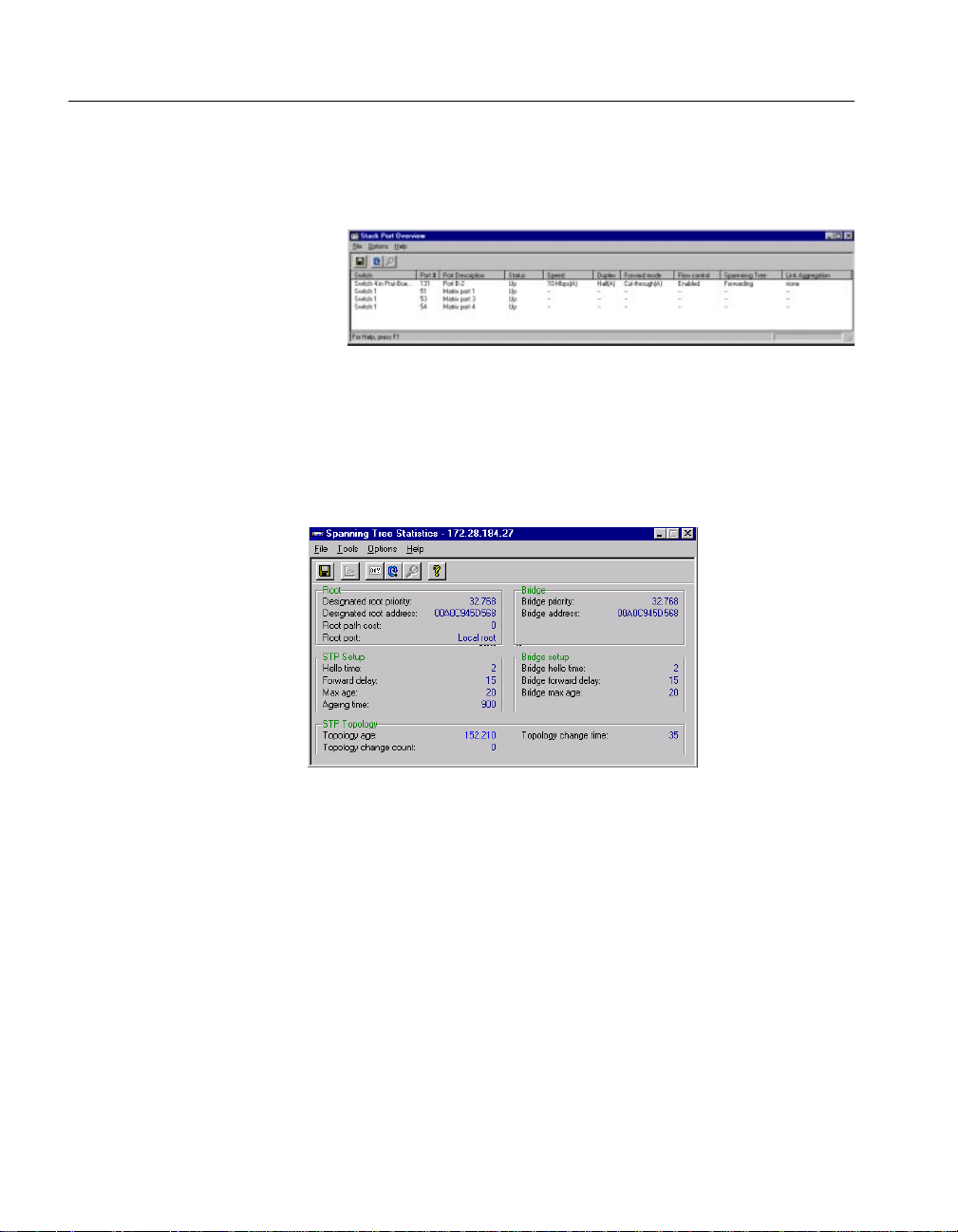
C H A P T E R 5 Managing the Switch
Overview of all the ports
Monitoring the spanning
tree statistics
To view the setups of all the ports in the stack:
1 Right-click the stack border and select Port Overview.
2 Double-click a port to get the specific details for that port: port
performance, faults, distribution and spanning tree information.
To view the spanning tree statistics for the whole switch, right-click
a specific switch and select
Spanning Tree.
82
Page 93
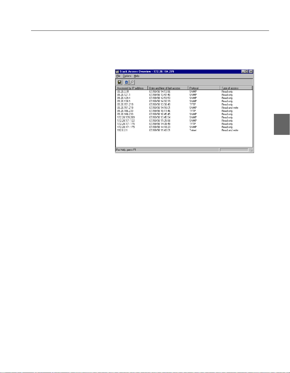
C H A P T E R 5 Managing the Switch
Stations on the switch
To view the IP addresses of the devices on the switch:
1 Select Monitoring>Access Overview.
2 To change the order of the information, click the appropriate
title bar.
Monitoring VLANs
General information The information provided in th is section is switch spec ific. To get in-
formation about a switch, including switches in a stack, right-click
that switch.
83
Page 94

C H A P T E R 5 Managing the Switch
Overview of the VLANs on
a switch
To view the VLANs on the switch:
1 Select VLAN>Monitoring.
This shows a full list of VLANs active on the switch or in the
domain (if distributed VLAN or stand-alone for a stack). To
view this window from the Explorer, right-click the VLAN
name and select
2 Click the name of the VLAN, then click Details to view
Monitor.
details of that VLAN:
Click either of the t abs to view more details:
84
Tab Name:
Shows the
VLAN’s...
Station Table MAC addresses,
Ports and
IP addresses
Port Table Port number and
Port name
Double-click a row
to show...
all VLANs in which
this address is contained
the MAC and IP
address of all devices
on the port in this
VLAN
IP addresses will be present on ly if t he stat i on is l earned by t hi s
switch and has sent an ARP packet.
Page 95

C H A P T E R 5 Managing the Switch
Information about the
domain
Information about VLAN
configuration
To view the VLAN mode and Domain name:
1 Select VLAN>Status.
2 To change the information, see “Changing VLAN mode” in
“VLANs (Virtual LANs)”, p. 68.
To see if another user is configuring the VLANs, view the version
number of the VLAN configuration or the time this configur ation has
been running:
1 Select VLAN>Status.
2 Click Configuration Information
The bottom 2 lines in this window are not displayed when the
status is idle, for example nobody is editing the VLAN.
85
Page 96

C H A P T E R 5 Managing the Switch
Information about the
server
VLAN links to other
switches
This provides status information about the server:
Note This information is only available from switches in a stack
or from switches in a distributed VLAN.
1 Select VLAN>Status.
2 Click Server Information
To view the links between switches in a distributed VLAN:
Note This information is only available from switches in a stack
or from switches in a distributed VLAN.
1 Select VLAN>Switch VLAN Links.
This shows the IP address and MAC address of the other
switches connected to each port in this distributed VLAN.
2 Click the appropriate title bar to change the order of the infor-
mation.
Monitoring the Port’s Performance
Using the LEDs Using the Device View of the switch, the different colored LEDs on
Help>Dis-
86
the ports indicate the different states of activity. Select
play Legend
for further information on LED states.
Page 97

C H A P T E R 5 Managing the Switch
Monitoring the
performance of a port
To monitor the performance of a specific port:
1 Right-click the port.
2 Select Port Details>Performance.
This table shows the to tal number of frames and b ytes, utilization of the ports and the number of packets transmitted and
received.
3 To change the display from numerical to graphic al, click one or
more of the numbers and select
Tools>Graph.
Monitoring the faults on a
port
4 Select Options>Reset Counters to set all these counters
to zero.
To monitor the faults on a specific port:
1 Right-click the port.
2 Select Port Details>Faults.
This table shows the total number errors, discards and observations transmitted and received.
3 To change the display from numerical to graphic al, click one or
more of the numbers and select
Tools>Graph.
4 Select Options>Reset Counters to set all these counters
to zero.
87
Page 98

C H A P T E R 5 Managing the Switch
Monitoring the distrib ution
on a port
Monitoring the spanning
tree statistics on a port
Monitoring the received
packets on a port
To monitor the distribution percentages of unicast, multicast and
broadcast frames on a specific port:
1 Right-click the port.
2 Select Port Details>Distribution.
To monitor the spanning tree statistics on a specific port:
1 Right-click the port.
2 Select Port Details>Spanning Tree.
To monitor the received packets on a specific port:
1 Right-click the port.
2 Select Port Activity>RX Packets:
Monitoring the packets
transmitted from a port
88
3 To change the graph, click 3D.
4 To freeze the graph, click View>Stop Collection.
To monitor the transmitted packets on a specific port:
1 Right-click the port.
2 Select Port Activity>TX Packets.
3 To change the graph, click 3D.
4 To freeze the graph, click View>Stop Collection.
Page 99

C H A P T E R 5 Managing the Switch
Monitoring the VLANs on
a port
To view the VLANs on the port:
1 Right-click and select VLAN Port Monitoring.
2 Click either of the tabs to view deta ils of that port:
Tab Name
Shows the
VLAN’s...
VLAN Table in which this port is
contained
Double-click a row
to show the...
MAC addresses
learned on this port in
that specific VLAN
MAC Table MAC addresses and
IP addresses
other VLANs in
which this address is
contained
RMON Interface statistics To access a range of subnet management statistics:
1 Right-click a port and select RMON Statistics.
2 This window gives more detailed information displayed as
graphs.
89
Page 100

C H A P T E R 5 Managing the Switch
Tools for the Switch
Tools available The switch has various tools to help with management:
Use... To...
Ping Ensure a device is connected to the net-
work.
Report Manager Transfer files from a remote switch to your
local disk or file server.
Telnet Access the switch from any workstation
on the network using Telnet.
Recovery Manager Regain control of your switch.
DNS IP Conversion Co nverts DNS names to IP addresses.
Ping
Pinging a device Use Ping to ensure a device is attached to the network. If the device
is on a remote network, you may need to adjust the timeout in order
to receive the response.
1 Select Tools>Ping.
2 Double-click IP Address, and type the correct IP addr ess for
the device you want to ping.
90
 Loading...