

Page 1

Intel Express 100BASE-TX Switching Hub
User Guide
Part No. 654655-001
Page 2

First edition March 1996
Copyright © 1996, Intel Corporation. All rights reserved.
Intel Corporation, 5200 NE Elam Young Parkway, Hillsboro, OR 97124-6497
Intel Corporation assumes no responsibility for errors or omissions in this manual. Nor does Intel make any commitment to
update the information contained herein.
* Other product and corporate names may be trademarks of other companies and are used only for explanation and to the
owners’ benefit, without intent to infringe.
Page 3

iii
Contents
Quick Start 1
Chapter 1 Hardware Installation and Network Topology 3
Overview ..................................................................................................................................................3
Features.....................................................................................................................................................4
Installation and Setup ...............................................................................................................................5
Using the Switch.......................................................................................................................................6
Port status LEDs ................................................................................................................................ 6
Management status LEDs..................................................................................................................7
Cabling Requirements ..............................................................................................................................8
UTP requirements ............................................................................................................................. 8
Fiber optic requirements ................................................................................................................... 9
Straight-through vs. crossover cables ............................................................................................... 9
Typical Configurations...........................................................................................................................10
Configuring the 100 Mbps workgroup environment ......................................................................10
Configuring the Wide Area Network (WAN) environment ........................................................... 11
Connecting to a 10 Mbps segment .................................................................................................. 12
Excessive flow control problems ....................................................................................................13
Chapter 2 Configuring and Managing the Switch 15
Accessing the Console Manager ............................................................................................................16
Using the Console Manager ...................................................................................................................17
Entering commands.........................................................................................................................17
Console Manager command groups................................................................................................19
Configuring a port for full duplex...................................................................................................20
Configuring the SNMP agent for IP................................................................................................20
Monitoring traffic ............................................................................................................................ 21
Creating VLANs ............................................................................................................................. 23
Configuring the spanning tree ......................................................................................................... 24
Creating custom filters ....................................................................................................................25
Page 4

iv
CONTENTS Intel Express 100BASE-TX Switching Hub User’s Guide
Console Command Reference ................................................................................................................26
System commands...........................................................................................................................28
IP commands ................................................................................................................................... 31
Ping commands ...............................................................................................................................34
SNMP commands............................................................................................................................36
Switching database commands ....................................................................................................... 38
VLAN commands ........................................................................................................................... 46
Spanning tree commands ................................................................................................................49
Port configuration commands .........................................................................................................51
Switching statistics commands........................................................................................................52
Console command-line summary ................................................................................................... 56
Chapter 3 Troubleshooting 59
Appendix A Technical Information 61
Default Configuration.............................................................................................................................61
Specifications ......................................................................................................................................... 62
SNMP and MIB Support ........................................................................................................................65
Custom Filter Port Table ........................................................................................................................66
Limited Warranty ................................................................................................................................... 71
Index 73
Customer Support Inside back cover
Page 5
1
Intel Express
100BASE-TX Switching Hub
Console Mgmt
SNMP Pwr
Mgmt Fault
MDI
MDI
Xmt FC/FD Mgm
Rcv Clsn Link
Xmt FC/FD Mgmt
Rcv Clsn Link
MDI
Xmt FC/FD Mgmt
Rcv Clsn Link
MDI
Xmt FC/FD Mgmt
Rcv Clsn Link
MDI
Xmt FC/FD Mgmt
Rcv Clsn Link
PC-3435
Xmt FC/FD Mgm
Rcv Clsn Link
Port 2
Port 7
Port 6Port 5Port 3 Port 4
Port 1
Rcv Clsn Link
Xmt FC/FD Mgm
100BASE-TX
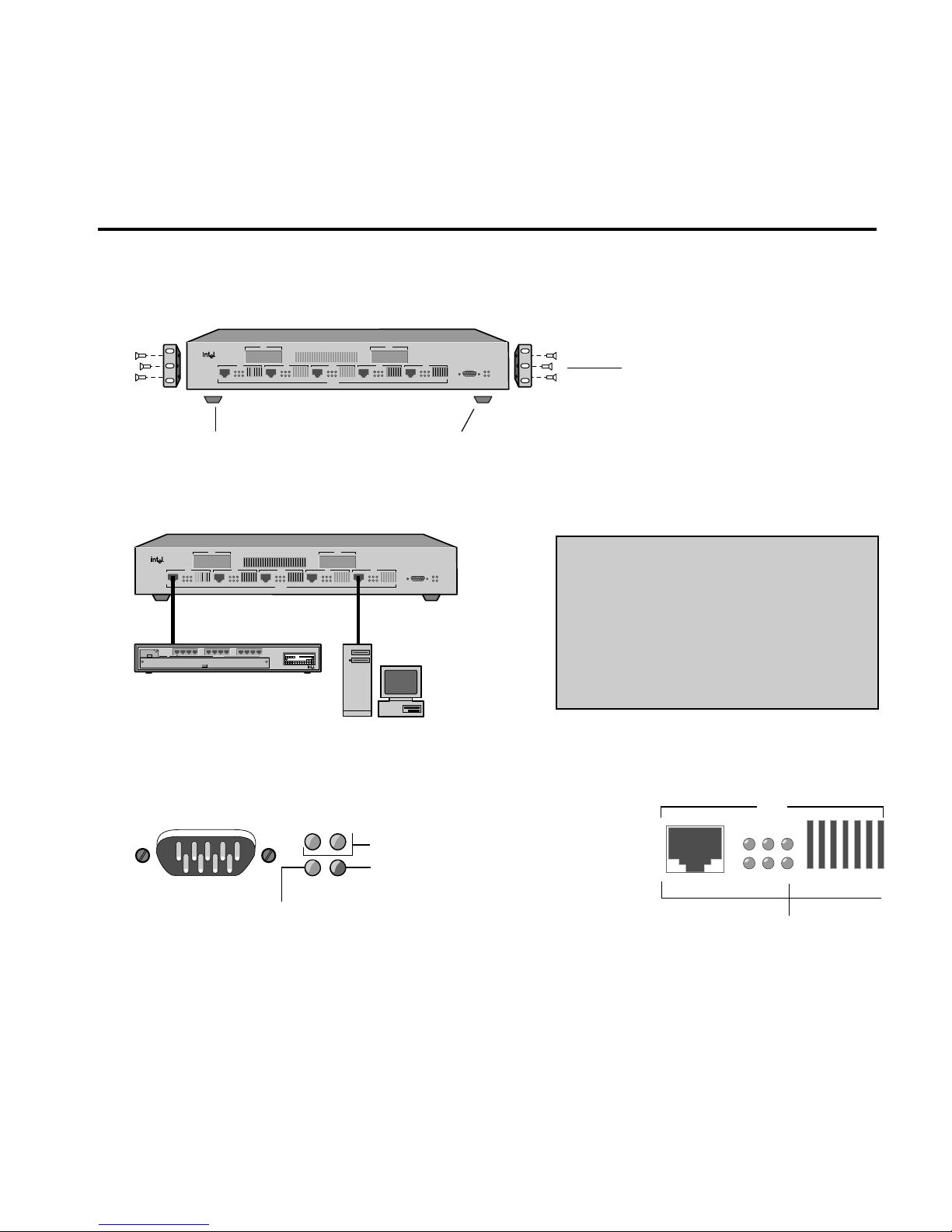
Rubber feet for shelf or table placement.
Brackets and screws for standard
19-inch equipment rack placement.
Crossover cables to
servers/workstations
Straight-through
cables to hubs
100BASE-TX server/
workstation
100BASE-TX hub
Intel Express
100BASE-TX Switching Hub
Console Mgmt
SNMP Pwr
Mgmt Fault
MDI
MDI
Xmt FC/FD Mgm
Rcv Clsn Link
Xmt FC/FD Mgmt
Rcv Clsn Link
MDI
Xmt FC/FD Mgmt
Rcv Clsn Link
MDI
Xmt FC/FD Mgmt
Rcv Clsn Link
MDI
Xmt FC/FD Mgmt
Rcv Clsn Link
PC-3436
Xmt FC/FD Mgm
Rcv Clsn Link
Port 2
Port 7
Port 6Port 5Port 3 Port 4
Port 1
Rcv Clsn Link
Xmt FC/FD Mgm
100BASE-TX
PwrStat RPSCol Data %
Expansion Slot
1
1132143154165176187198209211022112312
Mstr
Stat Enbl
Stat
24
Port Status
Media Adapter
Management
²1 5 10 15 25³30
100 BASE-T4
Expansion Slot
Media Adapter
1
243
65871091211
Intel Express
100BASE-T4 Stackable Hub
MDI
Xmt FC/FD Mgmt
Rcv Clsn Link
Port 3
Lights when device is
plugged into the port.
Console Mgmt
SNMP Pwr
Mgmt Fault
Blinks every two seconds.
Lights briefly while the switch
performs self-tests.
Should always be on.
NOTES
• Connect only 100 Mbps devices to the
switch. See page 12 for information on
connecting to 10 Mbps segments.
• The default configuration for each port is
half duplex mode only.
• Always use Category 5 cabling.
Quick Start
1. Install the Express 100BASE-TX Switching Hub in a rack or on a shelf or table,
plug the cord in, and turn the power on. See page 5 (steps 1 and 2).
2. Connect the network devices to the switch. See page 5 (step 3) and pages 10–12.
3. Check the LEDs for power and links. See pages 6 and 7.
Next steps (Optional)
• Continue to the next page if you want to configure the switch to work with an SNMP-compliant
Network Management System (NMS).
• See Chapter 2 if you want to use the Console Manager to change port configurations (set a port for
full duplex), assign an IP address, or check port statistics.
Page 6

2
(Optional) Quick Start for SNMP Management
4. Use the null-modem cable to connect the Console Mgmt port to a COM port on a
workstation.
5. Open a terminal emulation program (such as Terminal in Microsoft Windows* 3.1).
Specify these communication parameters:
• 9600 baud
• 8 data bits
• No parity
• 1 stop bit
6. Press
EE
EE
E and log into the Console Manager:
Login:
password:
By default, no password or user name is assigned. If you enter one, it is saved upon reset.
7. Set the IP configuration using the set-ip-conf command:
set-ip-conf 192.1.1.64 255.255.255.0 192.1.1.255 E
Replace these addresses with the numbers for your network. Specify the IP address, netmask
(subnet mask), and broadcast address, in that order.
8. Download the Intel MIB (Management Information Base) file from an Intel online
service and compile into your NMS.
The MIB filename is SWCH1MIB.EXE. You can find the file on Intel’s Customer Support web
site (http://www-cs.intel.com) or the Intel BBS (see inside back cover). See your NMS
documentation for instructions on compiling the MIB for a new device.
Console Mgmt
A null-modem cable is
provided with the switch.
PC-3442
Page 7

3
Hardware Installation
and Network
Topology
Overview
The Intel Express 100BASE-TX Switching Hub is a 5-port Fast
Ethernet switch featuring five 100BASE-TX ports and two slots for
optional 100BASE-TX or 100BASE-FX media adapters. Each 100
Mbps port supports a Fast Ethernet segment, up to a total of 1024
cached nodes for the switch.
The switch increases the available bandwidth and extends the distance
of Fast Ethernet installations by dividing the network into segments
and insulating each from the others’ local traffic. Additionally, by
configuring a link for full duplex, you can establish a 200 Mbps link
between the switch and another switch, server, or workstation. This is
especially useful for busy file servers that are accessed by multiple
segments.
Data transfer delays are eliminated through the switch’s parallel storeand-forward architecture with direct port-to-port transfer. Selective
flow control improves performance by preventing lost packets due to
buffer overload.
1
Page 8

4
CHAPTER 1 Intel Express 100BASE-TX Switching Hub
Security features include the creation of custom filters and virtual
networks (VLANs). You can define any custom filter based on
multicast/broadcast, source port, destination port, and destination
address. VLAN features include the ability to set broadcast or
multicast domains. See Chapter 2 for information on configuring
VLANs.
The switch also has a built-in SNMP (Simple Network Management
Protocol) agent and can be monitored and controlled through any
SNMP-compliant Network Management System (NMS). See page 20
for information on using the switch with an SNMP NMS and getting
the switch’s MIB (Management Information Base) file.
Features
• Five RJ-45 Fast Ethernet ports
• Two expansion ports for optional 100BASE-TX or 100BASE-FX
media adapters
• Standard 19-inch rack-mount chassis (rack-mount kit included)
• Auto-ranging power supply (automatically adjusts to any voltage
between 90 VAC and 264 VAC at 50/60 Hz)
• Full duplex selectable on each port
• Flow control selectable on each port
• 1024 address cache entries
• Custom filtering table
• Serial console port with password protection
• SNMP support (see Appendix A for MIB information)
• Spanning tree protocol support
• Built-in remote monitoring (RMON) support (Group 1)
Page 9

5
Hardware Installation and Network TopologyCHAPTER 1
Installation and Setup
1 Install the switch in a rack or on a shelf.
For rack placement, connect the switch to a 19-inch rack using the
enclosed rack mount brackets.
For shelf placement, attach the enclosed rubber feet to each corner of
the bottom of the switch and place it on a flat, level surface.
2 Plug the switch in and turn the power on.
Plug the switch into an active AC outlet and turn the power on. A
built-in power supply automatically adjusts to any outlet providing
between 90 VAC and 264 VAC at 50/60 Hz.
3 Connect the Fast Ethernet devices.
For optimum performance, the Fast Ethernet segments connected to
the switch must be configured carefully. Follow these general
guidelines:
• Connect only 100 Mbps devices to the switch. The switch will not
work with 10 Mbps devices. See page 12 for information on
connecting to a 10 Mbps segment.
• Always use Category 5 unshielded twisted-pair (UTP) cable when
plugging devices into 100BASE-TX ports.
• Limit the distance between devices connected with UTP cable to
100 meters.
• Use a crossover cable when directly connecting a workstation,
server, or another switch to the switch. Use straight-through
cables when connecting to a repeating hub or concentrator.
• Configure the network so devices that primarily talk to each other
are on the same segment. Each port on the switch is defined as a
single Fast Ethernet segment.
4 Is setup complete?
If you’re using the switch as a stand-alone device (not under the
control of network management software), you’re done.
If you want to change the default configuration (shown in
Appendix A) or manage the switch, continue to Chapter 2.
NOTE
The switch will only work with
100 Mbps devices. For a
10BASE-T connection, see
page 12.
Page 10
6
CHAPTER 1 Intel Express 100BASE-TX Switching Hub
Using the Switch
The switch requires minimal user intervention. It automatically learns
the addresses of new stations as they appear, and will relearn
addresses dynamically if the network is reconfigured.
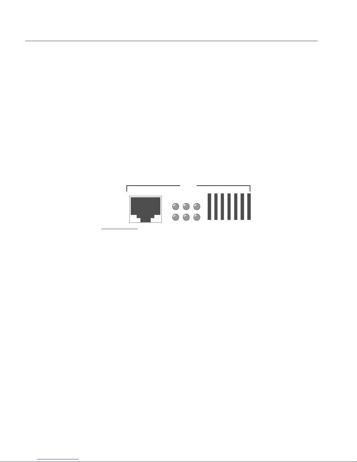
Each of the Fast Ethernet ports has six status LEDs. There is a
separate bank of four LEDs for the management status.
Port status LEDs
Port LEDs provide information about the port’s configuration and the
status of devices connected to the ports.
MDI
Xmt FC/FD Mgmt
Rcv Clsn Link
Port 3
Xmt Transmit. Lights when the switch is transmitting
packets on this port.
Rcv Receive. Lights when packets are received on this port,
even if they are not forwarded.
FC/FD Flow Control (default) or Full Duplex. Blinks on when
flow control is activated. If flow control is disabled, the
LED blinks on when a packet is lost. If full duplex is
enabled on the port, the LED is normally on
continuously, and blinks off when a packet is resent.
Flow control is not possible, nor needed, when full
duplex is enabled.
Clsn Collision. Lights whenever a collision occurs while the
port is transmitting. Collisions are normal in an Ethernet
environment. However, if the collision LED is on
continuously, you may have a problem with a device on
the segment.
NOTE
The default configuration of
all ports is half-duplex mode.
To change to full duplex, use
the Console Manager. See
page 19 for instructions.
Ports on the switch are wired
MDI for connection to MDI-X
ports using a straight-through
UTP cable. See page 9 for
more information.
Page 11

7
Hardware Installation and Network TopologyCHAPTER 1
Mgmt Management. Lights when the management agent
checks the port (normally, every two seconds).
Link Link. When solid, indicates a connection is established.
If the Link LED is off, check for loose cable
connections. Also, make sure you’re using the correct
type of Category 5 cable, either straight-through or
crossover. See page 9 for more information.
Management status LEDs
Management status LEDs provide information about the overall
operation of the switch and its SNMP management components.
Console Mgmt
SNMP Pwr
Mgmt Fault
SNMP Simple Network Management Protocol. Always
on, indicating that the built-in SNMP agent is working.
Mgmt Management. Blinks on at regular intervals as the
SNMP agent is polled for updated information.
Pwr Power. Indicates the status of the power supply. It may
remain off for a few seconds during the power-on selftest. It is normally on.
Fault Fault. Indicates that the switch has detected a
problem. It may remain on for a few seconds during the
power-on self-test. If this indicator blinks or remains lit
after self-test, there is a problem with the switch.
See Chapter 3 for troubleshooting information.
Page 12

8
CHAPTER 1 Intel Express 100BASE-TX Switching Hub
Cabling Requirements
Incorrect cabling is often the cause of network configuration
problems. It’s important that you understand cabling requirements
before connecting Fast Ethernet devices to the switch.
UTP requirements
The 100BASE-TX Fast Ethernet specification requires you use
Category 5 (CAT5) unshielded twisted-pair (UTP) cabling to operate
at 100 Mbps per second. If you use lower grade cabling (CAT3 or
CAT4), you’ll get a connection, but will soon experience data loss or
slow performance.
You’re limited to 100 meters between any two devices with UTP
cable. However, you can extend the total diameter by installing a fiber
optic media adapter and using fiber optic connections between
switches, or between the switch and a router or bridge.
See pages 10–11 if you’re unsure whether your network topology
meets these distance limitations.
Fiber optic requirements
The optional 100BASE-FX fiber optic media adapter (Intel product
code ESMODFX) lets you use multimode fiber optic cable to connect
two switches, or to connect the switch with a router or bridge. The
media adapter uses an SC fiber optic connector.
With multimode fiber optic cable, signals can travel up to 412 meters
with no repeater when the link is configured at half duplex. If
configured at full duplex, the signal can travel up to 2 km.
Page 13

9
Hardware Installation and Network TopologyCHAPTER 1
Straight-through vs. crossover cables
Ports on the switch are wired MDI so you can use a straight-through
cable when connecting to a Fast Ethernet repeating hub port, which is
usually wired MDI-X. For direct connection to another MDI port
(workstation, server, or another switch), you must use a crossover
cable. The pinouts of MDI and MDI-X ports are shown below.
Connector pinouts
Switch or NIC RJ-45 (MDI) Hub RJ-45 (MDI-X)
1TX+ 1RX+
2 TX- 2 RX3 RX+ 3 TX+
4 Unused 4 Unused
5 Unused 5 Unused
6 RX- 6 TX7 Unused 7 Unused
8 Unused 8 Unused
Determining which cable to use
Different switch and repeater manufacturers implement their port
configurations differently. The following guidelines are based on the
Intel Express 100BASE-TX Switching Hub (switch), the Intel Express
100BASE-TX Stackable Hub (repeater) and the EtherExpress™
family of adapters (server or workstation). These apply to the majority
of switches and hubs:
For this connection Use this cable
Switch to repeater Straight-through
Switch to server or workstation Crossover
Switch to switch Crossover
Repeater to server or workstation Straight-through
NOTE
When making your own
cables, wires 1 and 2
must be a twisted pair
and 3 and 6 must be a
twisted pair.
Page 14
10
CHAPTER 1 Intel Express 100BASE-TX Switching Hub
Typical Configurations
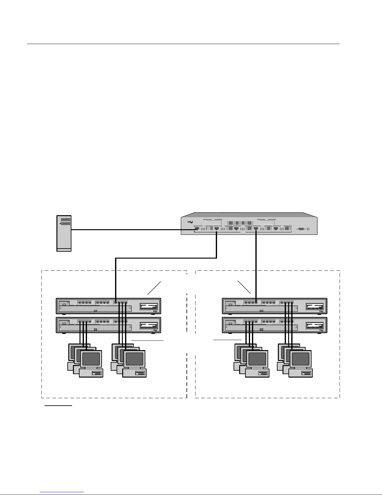
Configuring the 100 Mbps workgroup
environment
In the 100 Mbps environment, workgroup clients should be connected
to a 100 Mbps hub such as the Intel Express 100BASE-TX Stackable
Hub. All hub stacks should be connected to the Express Switching
Hub. By connecting the hubs to a switching environment, you can
extend Fast Ethernet distance limitations.
Crossover cable
Intel Express
100BASE-TX Switching Hub
Console Mgmt
SNMP Pwr
Mgmt Fault
MDI
MDI
Xmt FC/FD Mgm
Rcv Clsn Link
Xmt FC/FD Mgmt
Rcv Clsn Link
MDI
Xmt FC/FD Mgmt
Rcv Clsn Link
MDI
Xmt FC/FD Mgmt
Rcv Clsn Link
MDI
Xmt FC/FD Mgmt
Rcv Clsn Link
Port 7
Port 6Port 5Port 3 Port 4
100BASE-TX
Pwr StatRPS Col Data %
Expansion Slot
1
1132143154165176187198209211022112312
Mstr
Stat Enbl
Stat
24
Port Status
Media Adapter
Management
²1 5 10 15 25 ³30
100 BASE-T4
Expansion Slot
Media Adapter
1
243
65871091211
Intel Express
100BASE-T4 Stackable Hub
Pwr StatRPS Col Data %
Expansion Slot
1
1132143154165176187198209211022112312
Mstr
Stat Enbl
Stat
24
Port Status
Media Adapter
Management
²1 5 10 15 25 ³30
100 BASE-T4
Expansion Slot
Media Adapter
1
243
65871091211
Intel Express
100BASE-T4 Stackable Hub
Pwr StatRPS Col Data %
Expansion Slot
1
1132143154165176187198209211022112312
Mstr
Stat Enbl
Stat
24
Port Status
Media Adapter
Management
²1 5 10 15 25 ³30
100 BASE-T4
Expansion Slot
Media Adapter
1
243
65871091211
Intel Express
100BASE-T4 Stackable Hub
Pwr StatRPS Col Data %
Expansion Slot
1
1132143154165176187198209211022112312
Mstr
Stat Enbl
Stat
24
Port Status
Media Adapter
Management
²1 5 10 15 25 ³30
100 BASE-T4
Expansion Slot
Media Adapter
1
243
65871091211
Intel Express
100BASE-T4 Stackable Hub
PC-3437
Port 1
Port2
100 Mbps clients using
Intel EtherExpress™ PRO/100 adapters
Segment 2
Segment 1
Dedicated 100 Mbps link
to file server
Straight-through cable
CAT5 UTP (100 meters max.)
Straight-through cable
Intel Express 100BASE-TX
Stackable Hubs
Straight-through
cables
100 Mbps clients using
Intel EtherExpress PRO/100 adapters
Page 15
11
Hardware Installation and Network TopologyCHAPTER 1
Pwr StatRPS Col Data %
Expansion Slot
1
1132143154165176187198209211022112312
Mstr
Stat Enbl
Stat
24
Port Status
Media Adapter
Management
²1 5 10 15 25 ³30
100 BASE-T4
Expansion Slot
Media Adapter
1
243
65871091211
Intel Express
100BASE-T4 Stackable Hub
PC-3438
Intel Express
100BASE-TX Switching Hub
Console Mgmt
SNMP Pwr
Mgmt Fault
MDI
MDI
Xmt FC/FD Mgm
Rcv Clsn Link
Xmt FC/FD Mgmt
Rcv Clsn Link
MDI
Xmt FC/FD Mgmt
Rcv Clsn Link
MDI
Xmt FC/FD Mgmt
Rcv Clsn Link
MDI
Xmt FC/FD Mgmt
Rcv Clsn Link
Port 2
Port 7
Port 6Port 5Port 3 Port 4
Port 1
100BASE-TX
Pwr StatRPS Col Data %
Expansion Slot
1
1132143154165176187198209211022112312
Mstr
Stat Enbl
Stat
24
Port Status
Media Adapter
Management
²1 5 10 15 25 ³30
100 BASE-T4
Expansion Slot
Media Adapter
1
243
65871091211
Intel Express
100BASE-T4 Stackable Hub
Pwr StatRPS Col Data %
Expansion Slot
1
1132143154165176187198209211022112312
Mstr
Stat Enbl
Stat
24
Port Status
Media Adapter
Management
²1 5 10 15 25 ³30
100 BASE-T4
Expansion Slot
Media Adapter
1
243
65871091211
Intel Express
100BASE-T4 Stackable Hub
Pwr StatRPS Col Data %
Expansion Slot
1
1132143154165176187198209211022112312
Mstr
Stat Enbl
Stat
24
Port Status
Media Adapter
Management
²1 5 10 15 25 ³30
100 BASE-T4
Expansion Slot
Media Adapter
1
243
65871091211
Intel Express
100BASE-T4 Stackable Hub
Intel Express
100BASE-TX Switching Hub
Console Mgmt
SNMP Pwr
Mgmt Fault
MDI
MDI
Xmt FC/FD Mgm
Rcv Clsn Link
Xmt FC/FD Mgmt
Rcv Clsn Link
MDI
Xmt FC/FD Mgmt
Rcv Clsn Link
MDI
Xmt FC/FD Mgmt
Rcv Clsn Link
MDI
Xmt FC/FD Mgmt
Rcv Clsn Link
Port 2
Port 7
Port 6Port 5Port 3 Port 4
Port 1
Rcv Clsn Link
Xmt FC/FD Mgm
100BASE-TX
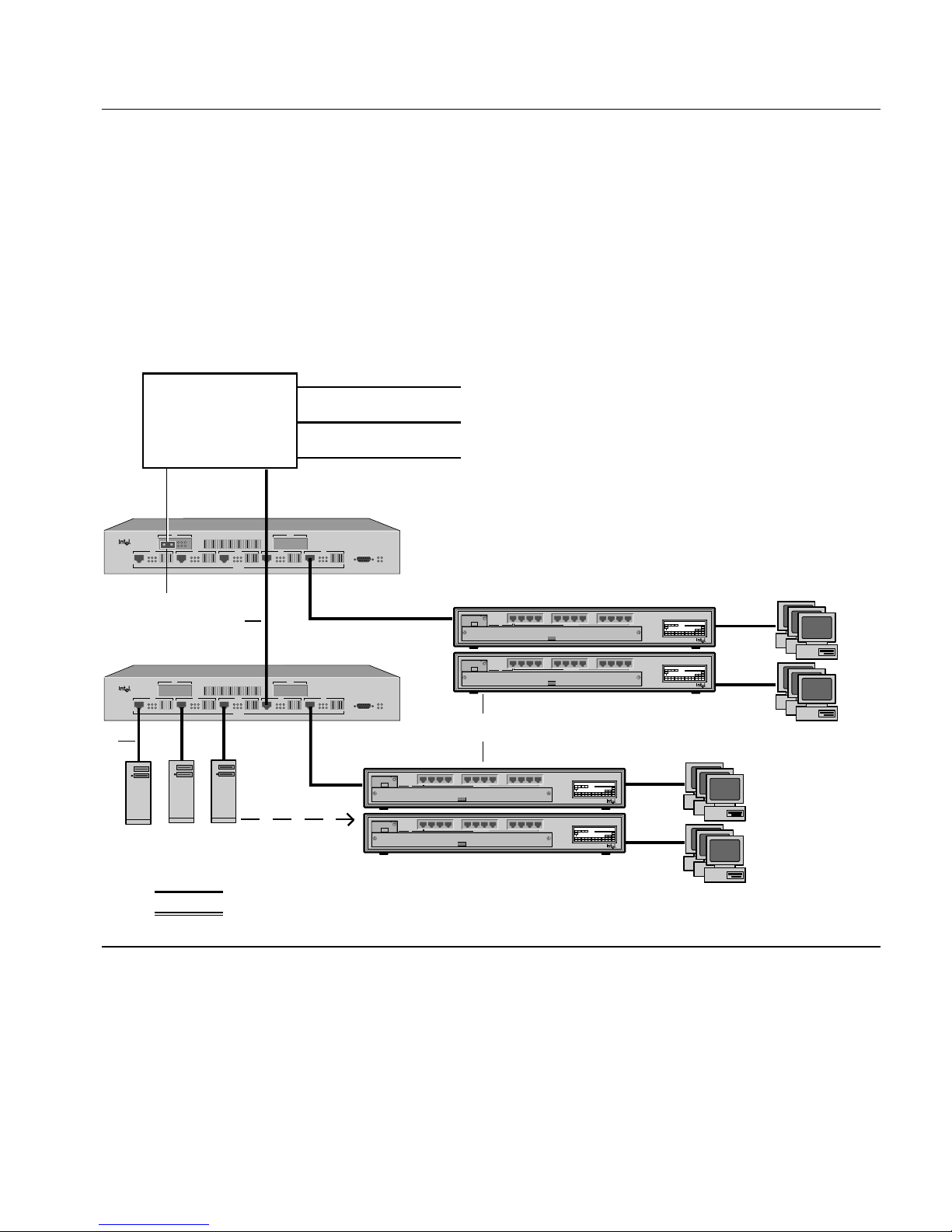
Backbone
Router, Bridge,
or Switch of
Switches
To dissimilar LANs
CAT5 UTP (100 meters max.)
High speed 100 Mbps
servers
To T1 line
To 10 Mbps segment
NOTES
➊ 100BASE-FX Fiber optic media adapter optional (product code ESMODFX).
➋ You can also use CAT5 UTP to connect to a backbone router or bridge.
➌ Configure high-speed servers for full duplex to achieve 200 Mbps throughput.
➍ If a server isn’t accessed by more than one segment, move it to a hub on the
segment.
➊
➋
➌
➍
Intel Express 100BASE-TX Stackable Hubs
Multimode fiber (412 meters max. at
half duplex, 2 Km max. at full duplex)
Configuring the Wide Area Network
(WAN) environment
Connections to the backbone are most effective using fiber optic
cabling. This eliminates the 100 meter UTP restriction. Also, connect
multiple switches directly to the backbone (not each other) and
connect busy servers directly to the switch.
Page 16
12
CHAPTER 1 Intel Express 100BASE-TX Switching Hub
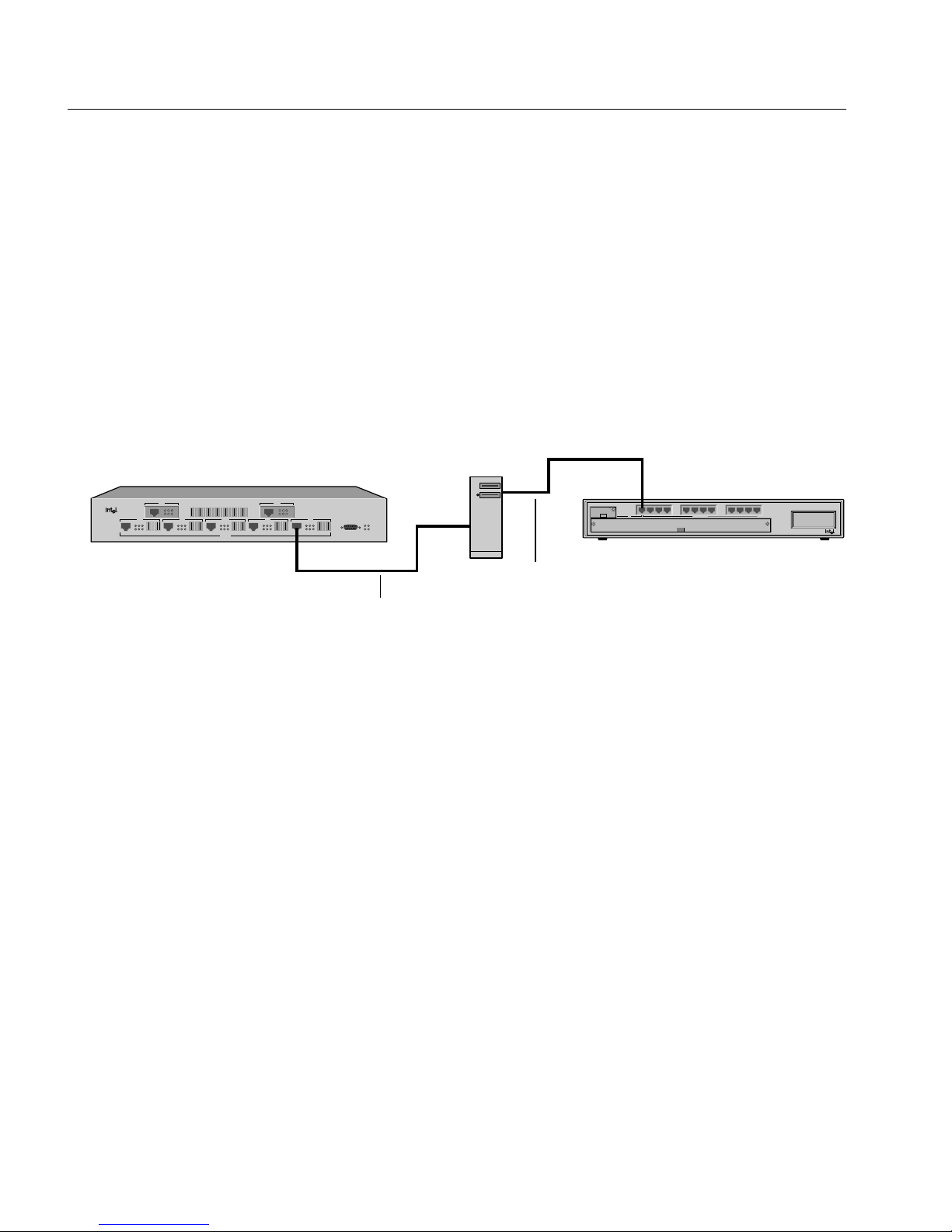
Connecting to a 10 Mbps segment
The Express Switching Hub is a 100 Mbps-only switch. You can’t
connect a 10 Mbps device directly to the switch.
The preferred way to connect the segments is by using a bridge,
router, or a 100 Mbps uplink module for your 10 Mbps hub (there
isn’t a 10 Mbps uplink module available for the Express switching
hub). However, this is costly if you don’t already have the equipment.
An inexpensive alternative is to connect the segments through a
server.
Several adapters on the market (such as the Intel EtherExpress PRO/
100 adapter) operate at either 10 or 100 Mbps. By connecting the
Express 100BASE-TX Switching Hub to one server adapter at 100
Mbps and your 10BASE-T hub to a separate adapter at 10 Mbps in the
same server, you can route traffic from the 10 Mbps segment to the
100 Mbps segment through your Network Operating System (NOS).
If your NOS doesn’t support multi-protocol routing (Windows 95
peer-to-peer and Windows for Workgroups* don’t), you must use a
Fast Ethernet switch or router that supports both 10 Mbps and 100
Mbps.
10BASE-T repeating,
sharing, or switching hub
100 BASE-T4
Expansion Slot
Media Adapter
1
243
65871091211
Intel Express
100BASE-T4 Stackable Hub
PC-3439
Intel Express
100BASE-TX Switching Hub
Console Mgmt
SNMP Pwr
Mgmt Fault
MDI
MDI
Xmt FC/FD Mgm
Rcv Clsn Link
Xmt FC/FD Mgmt
Rcv Clsn Link
MDI
Xmt FC/FD Mgmt
Rcv Clsn Link
MDI
Xmt FC/FD Mgmt
Rcv Clsn Link
MDI
Xmt FC/FD Mgmt
Rcv Clsn Link
Xmt FC/FD Mgm
Rcv Clsn Link
Port 2
Port 7
Port 6Port 5Port 3 Port 4
Port 1
Rcv Clsn Link
Xmt FC/FD Mgm
100BASE-TX
Server equipped with two
adapters, one at 100
Mbps and one at 10 Mbps
Express 100BASE-TX
Switching Hub
Crossover cable connecting the
server to the switching hub
Straight-through cable connecting the
server to the repeater
NOTE
Windows NT* 3.51 doesn’t
include the multi-protocol
router software by default.
You can download it from the
Microsoft World Wide Web
site.
Page 17

13
Hardware Installation and Network TopologyCHAPTER 1
Excessive flow control problems
During times of peak network usage, you may occasionally see the
FC/FD LED blink (for a description of the LED, see page 6). This is
normal. However, if it stays lit for more than a few seconds at a time,
or if there’s an excessive number of flow controls reported by the
network management software, it could indicate a problem with your
network configuration.
A port’s FC/FD LED indicator flashes whenever a packet is received
that needs to be forwarded to a port that already has too many packets
queued. This indicates a temporary overload situation on one port; the
total traffic to the port exceeds the amount the buffer can hold. This
typically occurs when there are several fast machines on different
ports trying to access a machine across the switch. If this is
infrequent, you don’t need to do anything. However, if this occurs
often on the network, then the devices causing flow control to activate
should be identified and moved to the same segment as the device that
they are talking to.
When Ethernet bandwidth is temporarily insufficient for the traffic,
there are only three possible actions: drop packets, use flow control,
or segment the network. Buffering packets only works for a very short
while. An extended overload will eventually overflow buffers and
cause dropped packets. Flow control stops transmission on a port and
forces devices to resend packets, ensuring that packets aren’t lost.
This is the most reasonable solution, since it relies on Ethernet’s
inherent collision detection mechanism to relieve temporary overload.
Repeater count limitations
The switch doesn’t count as a repeater. Each port on the switch can
support a full Fast Ethernet network. There can be one repeater/hub
between the switch and any workstations or servers (a stack of Intel
Express 100BASE-TX Hubs counts as a single hub). Also, the total
diameter of a segment can’t exceed 200 meters when using UTP
cable. That is, the distance between any two nodes on a segment (or
the switch and a node on the other side of a hub) can’t exceed 200
meters.
NOTE
By default, flow control is
enabled on all ports.
If you configure a port for full
duplex, flow control is automatically disabled.
Page 18

Page 19

15
2
Configuring and
Managing the Switch
You don’t need to read this chapter unless you want to change the
Express Switching Hub’s default configuration (see Appendix A for a
list of defaults) or intend to manage the switch. The switch is ready to
go simply by plugging it in and turning the power on.
However, if you need to change the default configuration or manage
the switch, there are two ways:
• Use SNMP-compliant management software (not included).
However, you must first use the Console Manager to assign an IP
address to the switch.
• Use the Express Switching Hub’s internal Console Manager.
Page 20

16
CHAPTER 2
Intel Express 100BASE-TX Switching Hub
Accessing the Console
Manager
The Console Manager software is contained in the switch’s
nonvolatile RAM (NVRAM); you don’t need to install any software.
To access the Console Manager:
1 Use the null-modem cable (included with the switch) to connect a
workstation’s COM port to the Console Mgmt port on the switch.
Console Mgmt
2 Open a terminal emulation program (such as Windows Terminal).
3 Select the COM port and these communication parameters:
9600 baud, eight data bits, no parity, one stop bit
In Windows Terminal, choose Communications from the Setting
menu.
4 Press E. The login prompt appears:
Login:
password:
By default, no login name or password is assigned. The password
you enter becomes active only after you reset the switch or turn
off the power. If you want the password to take effect
immediately, use the set-passwd command.
Accessing the Console Manager remotely
To access remotely through Telnet, you must first set the IP
configuration of the switch using the set-ip-conf command (see
page 32 for instructions). You can then use Telnet to reach the switch.
In a remote session, all commands work exactly as if a terminal were
directly connected to the Console Mgmt port. Note that only one
console session can be active at a time. After the first Telnet session is
established, the switch refuses other Telnet connections until the
current session is closed. To terminate an active Telnet session, press
E three times from the serial interface.
PC-3442
Page 21

17
Configuring and Managing the Switch
CHAPTER 2
Using the Console Manager
The Console Manager provides an out-of-band (not on the network)
connection to the switch. Use the Console Manager to
• assign an IP configuration to the switch.
• configure the ports.
• monitor network performance.
• create VLANs.
Entering commands
To enter commands, type the command name followed by any
parameters and press E. For example, typing sys-stat E
at the command prompt displays basic system status information.
Items in angle brackets represent values. For example,
<IPaddress>
represents an IP address in dotted decimal notation (such as
123.1.1.7).
Items in { } and separated by | represent alternatives for an
argument. For example,
get-comm {read|write|*}
means you can type one of the following
get-comm read
get-comm write
get-comm *
If you enter a command incorrectly, a message indicates the type of
error that occurred. For example, typing a nonexistent command gives
the following message:
SYS_console> pin
command <pin> not found
If the command exists but the number of parameters is incorrect, the
following message is displayed:
SYS_console> ping
too few arguments
Page 22

18
CHAPTER 2
Intel Express 100BASE-TX Switching Hub
Commands sometimes have parameters that determine how they’re
saved and when they’re implemented. Some are changed in
• the running database so that the new value is used immediately
(the run option).
• the NVRAM so that the changes are saved and occur only in the
next session (the nvram option).
• both the running and the NVRAM databases (the all option).
To get an explanation of a command’s parameters, add a question
mark (?) after the command name:
SYS_console> set-lt-age ?
set-lt-age sets the LT aging period
[arg #0] database type - either {run|nvram|all}
[arg #1] aging time in seconds
The Console Manager provides a history of the last several
commands. To obtain the last command in the command history,
press ! or
cP at the prompt.
To correct a command line, use the following special keys (see the
help-kbd command):
• ! or cP - for the previous command
• cW - to delete the previous word
• cU - to delete the entire line
When you type a command that results in more than one screen of
text appearing, you can press Q to stop the process or any other key
to continue to the next screen.
Finally, you can press T to see the list of commands that start
with the text already typed. For example:
SYS_console> get-c T
Commands matching <get-c>
---------------------------------------------------
get-comm show current read or/and write community
get-con-matrix displays the VLAN connectivity matrix
get-colls-cnt gets the collision distribution counters per port
Page 23

19
Configuring and Managing the Switch
CHAPTER 2
Console Manager command groups
The Console Manager has several categories of commands:
• Console commands: help, banner, serial line setup, console
parameters setup.
• System commands: system status, reset commands, download
commands, and system debug commands.
• IP commands: IP address setup, parameter and information
display.
• SNMP agent commands: SNMP settings, management, and trap
options.
• Switching database commands: aging time management and
switching database entry management.
• Spanning tree commands: disabling or manually configuring the
spanning tree protocol.
• VLAN commands: management of security virtual LANs.
• Port configuration commands: duplex and other port settings.
• Switching statistics commands: traffic and packet counters.
The following sections explain some of the more commonly used
commands for configuring ports and monitoring traffic statistics.
Configuring a por t for full duplex
Commands used
set-port-dplex
Sets the duplex mode on the specified port.
get-port-cfg
Displays the current port configurations.
Configuring a port for full duplex allows the switch to send and
receive packets simultaneously with the destination device. To
establish a full-duplex link, both the switch and the destination device
must be configured for full duplex.
Additionally, the link must be to a switch, workstation, or server. You
cannot establish a full-duplex link to a device that broadcasts
incoming packets to every port on the device. This excludes most
shared hubs, repeaters, or concentrators.
NOTE
Setting a port to full duplex
automatically disables flow
control. Since collisions don’t
happen on a full-duplex link,
flow control isn’t needed.
Page 24

20
CHAPTER 2
Intel Express 100BASE-TX Switching Hub
NOTE
You must have a point-topoint connection to establish
a full-duplex connection
(shared hubs/repeaters/
concentrators aren’t capable
of full duplex). Additionally,
both points of the connection
must be configured for full
duplex.
To configure a port for full duplex
1 Configure the adapter or switch port on the other end for full
duplex.
2 Set the Express Switching Hub port to full duplex. This example
sets port 3 to full duplex:
set-port-dplex 3 full
3 Check the FC/FD LED. It should be solid yellow, indicating full
duplex.
Configuring the SNMP agent for IP
Commands used
set-ip-conf
Sets IP address, netmask, and broadcast address.
ping
Contacts another IP device.
The switch can be monitored and controlled through any SNMPcompliant network management system (NMS). First, you must
configure the SNMP agent by assigning an IP address.
To configure the SNMP agent
1 Set the IP configuration. Type the command:
set-ip-conf 192.1.1.64 255.255.255.0 192.1.1.255
If the switch doesn’t have an IP address, then the specified IP
configuration is changed immediately and saved in NVRAM.
If the switch is already configured, the command changes only the
NVRAM. To use the new parameters, reset the switch using the
warm-reset command.
2 Test the installation. Type the command:
SYS_console> ping 192.1.1.1 2
This example tests connectivity from the switch to a workstation
with an IP address of 192.1.1.1. For more information on the ping
command, see page 33.
3 Download the MIB from Intel’s Customer Support World Wide
Web site (http://www-cs.intel.com). The file is compressed in the
file SWCH1MIB.EXE.
4 Compile the MIB into your NMS. See your NMS documentation
for more information.
Page 25

21
Configuring and Managing the Switch
CHAPTER 2
Monitoring traffic
Commands used
get-br-cnt
Displays the packet statistics for a port. For a
complete description, see page 52.
get-eth-cnt
Displays the Ethernet counters for a port.
get-colls-cnt
Displays the collision distribution counters for a
port.
get-rmon-cnt
Displays the Ethernet RMON counters for a port.
get-sdist-cnt
Displays the packet size distribution counters for a
port.
get-mgm-brcnt
Displays the statistics for the management port.
clr-cnt
Resets the Ethernet and bridging statistics.
Use monitoring commands to determine the traffic volume from
specific ports or between ports. This allows you to determine the
traffic patterns of your network and adjust your network topology for
maximum efficiency.
Statistics are generated for the current session. Reset counters by
using the clr-cnt command, resetting the switch, or cycling the
power.
In general, keep devices that primarily talk to each other on the same
segment (remember, each port is a Fast Ethernet segment). For
example, if a high volume of traffic is forwarded from port 4 to port
3, determine which devices are generating traffic and move them to
the same segment. This often happens when users are accessing a
server on a separate segment. A change may not be efficient,
however, if users from several segments all access the same server
frequently.
To check traffic on a port
1 Determine the port you want to check.
2 Type the command:
SYS_console> get-br-cnt 3
Ethernet Switching Counters for port 3
====================================================
Frm Received OK : 1419681
Bytes Received : 842637991
Frm Filtered : 0
Page 26

22
CHAPTER 2
Intel Express 100BASE-TX Switching Hub
Frm to all ports : 0
Frm multicast : 16017
Frm lost/fctrl : 0
Transmit OK : 1404387
Forward to port : FRAMES BYTES
---------------------------------------------------- 1 : 0 0
2 : 0 0
3 : 218103808 60
4 : 1419823 842711315
5 : 0 0
6 : 0 0
7 : 0 0
====================================================
In this example, a station on port 3 is accessing a server on port 4. To
reduce the amount of traffic crossing the switch, the server should be
connected to a hub on port 3 instead of a hub on port 4. This keeps
traffic localized to the same Fast Ethernet segment.
Creating VLANs
Commands used
set-vbc-domain
Sets up a Virtual Broadcast Domain (VBD).
del-vbc-domain
Deletes a VBD.
get-vbc-tbl
Displays the VBD table.
set-sec-vlan
Sets up a security VLAN.
del-sec-vlan
Deletes a security VLAN.
get-svlan-tbl
Displays the security VLAN table.
There are two types of VLANs:
• Security VLANs (SVLANs). Ports in an SVLAN can exchange
packets only with other ports in the same SVLAN.
• VBDs: Ports in a virtual broadcast domain can exchange packets
only with other ports in the same VBD. However, they can see
broadcast frames from other ports in the same VBD.
Use only one type. Configuring both types in the same switch can
lead to unpredictable traffic patterns.
If you want a device to talk to multiple VLANs (for example, a
management workstation), apply a custom filter to the device. See
page 24 for instructions.
Page 27

23
Configuring and Managing the Switch
CHAPTER 2
To create an SVLAN
1 Determine the ports you want to group together.
2 Type the command:
set-sec-vlan all 3-4-5
This command groups port 3, 4, and 5 as an SVLAN immediately
and saves the entry in NVRAM. Replace all with nvram to save
the entry without changing it immediately or with run to change
the entry now without saving it.
3 To display a summary of saved SVLANs, type
get-svlan-tbl nvram
Any SVLANs created with the nvram or all option are
displayed.
To create a VBD
1 Determine the ports you want to group together.
2 Type the command:
set-vbc-domain run 3-5-6-7
This command groups port 3, 5, 6, and 7 as a VBD temporarily
(only until the next reset or power down). To save the entry and
have it take effect now, replace run with all.
3 To display a summary of saved VBDs, type
get-vbc-tbl nvram
Page 28

24
CHAPTER 2
Intel Express 100BASE-TX Switching Hub
Configuring the spanning tree
Commands used
get-stp Displays the spanning tree session state.
set-stp Enables or disables the spanning tree for the next
session.
get-st-bcfg Displays the spanning tree bridge parameters.
get-st-pcfg Displays the spanning tree port parameters table.
get-st-syscfg Displays the spanning tree system ports
configuration.
set-br-prio Sets the spanning tree bridge priority.
set-br-maxage Sets the spanning tree bridge maximum age.
set-br-hellot Sets the spanning tree bridge hello time.
set-br-fwdel Sets the spanning tree bridge forward delay.
set-prt-prio Sets the spanning tree port priority.
set-prt-enb Enables or disables a port spanning tree.
set-prt-pcost Sets the spanning tree port path cost.
Spanning tree is a protocol that determines which port is turned off in
a redundant configuration. Spanning tree is enabled anytime a packet
could potentially be caught in an infinite loop on the network (for
example, when two switches are connected to each other and also to
the same bridge). The protocol uses the port with the lowest-cost path
and turns off the other port. If one path fails, the other path is
automatically turned on.
Spanning tree is enabled by default. See the “Spanning tree
commands” section later in this chapter for more information.
Creating custom filters
Commands used
add-cf-entry
Adds a custom filter entry.
del-cf-entry
Deletes a custom filter entry.
get-lt-filter
Displays the filter for a given MAC address.
get-nv-cftbl
Displays all configured custom filters.
Page 29

25
Configuring and Managing the Switch
CHAPTER 2
Use custom filters to control where the switch forwards packets from
a given MAC address. Custom filters override VLANs. This is useful
when you want a device to talk to devices outside of its VLAN.
Filters are defined for a set of ports. For example, you can set a
custom filter that tells the switch to forward packets received on ports
3 and 4 to ports 6 and 7.
To set a custom filter
1 Determine the MAC address of the device you’re applying the
filter to.
2 Determine the switch ports where the device’s packets will arrive.
These are the source ports.
3 Determine the switch ports where the device’s packets will be
forwarded. These are the destination ports.
4 Use the Custom Filter Port Tables in Appendix A to find the
source and destination port hexadecimal equivalents.
5 Type the command:
add-cf-entry perm 00-A0-C9-11-11-11 C C0
This custom filter would send packets from the device with MAC
address 00-A0-00-11-11-11 arriving on ports 3 or 4 (hexadecimal
C) to both ports 6 and 7 (hexadecimal C0).
Console Command Reference
The console commands configure the Console Manager parameters
and interface.
Type ? at the Console Manager prompt to display a list of available
command topics and a short explanation of each. Type a name from
this list to display the commands under that topic.
NOTE
Source ports start with port 1.
Destination ports start with
port 0, which is the internal
SNMP management port.
Page 30

26
CHAPTER 2
Intel Express 100BASE-TX Switching Hub
SYS_console> ?
Commands groups are:
---------------------------------------------------
console Console related commands
system System related commands
ip IP related commands
snmp SNMP related commands
switch-db Switching Database related commands
vlan Virtual LANS related commands
port-cfg Port Configuration related commands
statistics Switching Statistics related commands
sp-tree Spanning Tree related commands
------------------------------------------------------------
use ! for prev. cmd, ^U to clr line, ^W to clr previous word
------------------------------------------------------------
When you find the command you need from one of these categories,
type the command followed by ? for a description of command
syntax.
help-kbd
Lists the console function keys.
SYS_console> help-kbd
? or TAB - for a list of the categories
! or ^P - for previous command
TAB - for command completion
^U - to clear the line
^W - to clear the previous word
banner
Displays the Express Switching Hub Console Manager logo.
clear
Clears the screen and displays the command prompt.
login
Exits the Console Manager, but does not disconnect a Telnet session.
Use this command to password protect the console terminal while a
Telnet session is running.
Page 31

27
Configuring and Managing the Switch
CHAPTER 2
logout
Ends the local Console Manager session and any Telnet session and
displays the login prompt for a new session.
set-prompt
set-prompt <
new_prompt
>
Sets the command-line prompt for the Console Manager to a more
meaningful prompt, such as the location of the switch or the name of
a workgroup. The default prompt is SYS_console>.
SYS_console> set-prompt R&D_grp>
CLI prompt change in the NVRAM OK
R&D_grp>
set-passwd
Changes the console password. The system first prompts you for the
old password. You can then type a new password and type it again for
verification. Passwords are never shown onscreen.
SYS_console> set-passwd
Enter old password:
Enter new password:
Enter new password again:
CLI running password changed
CLI password change in NVRAM OK
Password changed!
If you enter the old password incorrectly or fail to verify the new
password correctly, the password isn’t changed.
System commands
The system commands allow you to display and set system-related
parameters.
Page 32

28
CHAPTER 2
Intel Express 100BASE-TX Switching Hub
sys-stat
Displays general status information about the switch and its SNMP
agent hardware and software:
SYS_console>sys-stat
Intel Express Switching Hub
SNMP Agent Software - Version V2.2 Nov 7 1995 15:01:09
SNMP Object ID is : < .1.3.6.1.4.1.629.1.1.3 >
System MAC Address : 00-A0-C9-00-20-D9
Total uptime(hundredths of seconds ): 111151888
Total uptime(days, hh:mm:ss format): 12 days, 20:45:18.88
i/f 1 -- description [ Port 1 - missing ] —- status [DOWN]
i/f 2 -- description [ Port 2 - missing ] —- status [DOWN]
i/f 3 -- description [ Port 3 - 100 BaseTX Ethernet Port] -- status [up]
i/f 4 -- description [ Port 4 - 100 BaseTX Ethernet Port] -- status [up]
i/f 5 -- description [ Port 5 - 100 BaseTX Ethernet Port] -- status [up]
i/f 6 -- description [ Port 6 - 100 BaseTX Ethernet Port] -- status [up]
i/f 7 -- description [ Port 7 - 100 BaseTX Ethernet Port] -- status [up]
The screen displays the following information:
• SNMP agent software version and release date.
• Device SNMP object ID
• Device MAC address.
• System uptime (in 1/100 of a second) and in days, hours, minutes,
and seconds.
• Port description and status. Ports 1 and 2 appear as missing unless
you have optional media adapters installed.
warm-reset
Resets the SNMP agent software without resetting the switch (it
doesn’t disconnect existing connections). The switch configuration is
loaded from the values saved in NVRAM. The statistics counters are
also reset by this command.
cold-reset
Performs a cold reset, which is equivalent to turning the power off
and on again. Existing connections are also lost.
Page 33

29
Configuring and Managing the Switch
CHAPTER 2
get-last-err
Displays the most recent system failure, if any, for diagnostic
purposes.
SYS_console>get-last-err
System information since the last hardware reset
————————————————————————
Software resets number : 0
The system never encountered a fatal error
SYS_console>
init-nvram
Resets the NVRAM on the SNMP agent to default values. Changes
don’t take effect until you use the warm-reset or cold-reset
commands or cycle the power. Default values are listed in Appendix
A.
set-line-slip
set-line-slip {9600|19200|38400}
Changes the console serial port to SLIP mode for out-of-band SNMP
management. The argument to the command is the new baud rate for
the interface. SLIP can be used with a terminal server but not with a
modem. The SLIP interface can be configured using the
set-slip-conf console command. The serial port can be returned to
console mode by pressing E three consecutive times from a
terminal.
set-sw-file
set-sw-file <
filename
>
Sets the name of the file downloaded by TFTP (trivial file transfer
protocol). This command is used in case of an update to the switch’s
firmware. The file name must match the name of the agent software
file on a TFTP server. When TFTP is used, the per-packet
retransmission time-out value on the server (not the switch) must be
increased to 10 seconds, since the SNMP agent must first erase its
flash EEPROM, which takes about 30 seconds.
Page 34

30
CHAPTER 2
Intel Express 100BASE-TX Switching Hub
set-par-file
set-par-file <
filename
>
Sets the name of the SNMP agent parameter file downloaded by boot
PROM (BOOTP). This filename must match the name of the
parameter file on the BOOTP server. The format of the parameter file
is:
<switch_hardware_address> : <read_comm> : <write_comm>
Example:
00-A0-C9-00-01-23 : public : private
set-fg-param
set-fg-param <
dest
> <
source
> <
fill_byte
> <
length
>
Sets the frame generator parameters. The
dest
and
source
are dash-
separated hardware addresses in hex. The
fill_byte
is a single byte
used to fill the entire packet except for the first 12 bytes. The
length
is the total length of the packet excluding CRC.
start-fg
start-fg <
dport-bitmask
> <
count
> <
rate
>
Starts frame generation.
dport-bitmask
is a hex bitmask of which
ports to generate traffic on. For example, a
dport-bitmask
of 3E
sends frames to ports 2, 3, 4, 5, 6. Use the source port list on page 68
for hexadecimal bitmask equivalents. The
count
specifies the number
of frames to send on each port. A count of 0 sends packets until you
type the stop-fg command. The
rate
specifies the number of packets
per second to generate.
stop-fg
Stops the frame generator.
IP commands
This section lists the IP commands available from the command line
interface. In the sections that follow, IP Configuration lists general
configuration commands, Ping lists commands that describe the ping
ability of the agent, and Address Resolution Protocol lists ARP
commands.
Page 35

31
Configuring and Managing the Switch
CHAPTER 2
IP Configuration
get-ip
Shows the switch’s current IP address:
SYS_console> get-ip
The device IP address is: 129.001.001.064
SYS_console> _
If the switch doesn’t have an IP address assigned:
SYS_console> get-ip
The device has no IP address defined.
get-ip-conf
Shows the complete current IP configuration: IP address, netmask
(subnet mask), and broadcast address.
SYS_console> get-ip-conf
The device has no IP Address defined
SYS_console> get-ip-conf
The device IP address, netmask and broadcast are:
IP address : 129.001.001.064
IP netmask : 255.255.000.000
IP broadcast : 129.001.001.000
set-ip
set-ip <
IPaddress>
Sets the IP address of the switch (technically, the switch’s SNMP
agent). If no IP address was previously set (which is the default
configuration), the new value is used immediately and saved in
NVRAM. Otherwise, the new value is stored in NVRAM, but you
must use the warm-reset command or cycle the power for changes to
take effect.
Example:
set-ip 129.001.001.064
Device IP Address unchanged for this session
Device IP Address change in the NVRAM OK
The device NVRAM IP address will be:
IP address : 129.001.001.064
NOTE
If the IP configuration is not
specified, the agent will not
respond to any in-band requests, including ping messages and network
management applications.
Page 36

32
CHAPTER 2
Intel Express 100BASE-TX Switching Hub
set-ip-conf
set-ip-conf <
IPaddress> <netmask
> <
broadcast
>
Sets IP address, netmask (subnet mask) and broadcast IP address. If
no IP configuration was previously set (which is the default
configuration), the new values are used immediately and saved in
NVRAM. If a previous IP configuration was being used, the new
configuration is saved in NVRAM for the next session. To use the
new values immediately, use the warm-reset command or cycle the
power.
SYS_console> set-ip-conf 129.1.1.64 255.255.0.0 129.1.1.0
Device IP Address set for this session
Device IP Address change in the NVRAM OK
The device IP configuration in the next session will be:
IP address : 129.001.001.064
IP netmask : 255.255.000.000
IP broadcast : 129.001.001.000
get-bootp
Displays the current state of the BOOTP process. By default, BOOTP
is disabled.
set-bootp
set-bootp {enable|disable}
Enables or disables BOOTP. With BOOTP, the switch looks for a
BOOTP server at startup if no IP configuration is defined.
get-slip
Displays the current SLIP address. By default, no SLIP address is
assigned.
get-slip-conf
Displays the current SLIP configuration.
set-slip
set-slip <
IPaddress
>
Sets the SLIP address, which cannot be the same as the IP address.
set-slip-conf
set-slip-conf <
IPaddress
> <
netmask
> <
broadcast
>
NOTE
If you change the class of the
IP address, make sure you
also change the netmask. If
you don’t, the switch will
ignore the IP address change.
Check for the appropriate
netmask when you change the
IP address.
Page 37

33
Configuring and Managing the Switch
CHAPTER 2
Sets the SLIP configuration. The arguments are the same as
set-ip-conf earlier on this page.
get-gatew
Shows the default gateway. This is the default router to use when
accessing a different IP network.
set-gatew
set-gatew <
IPaddress
>
Sets the default gateway IP address, which specifies the router used to
access a different IP network. The default value for this setting is
0.0.0.0 (no gateway).
SYS_console> set-gatew 129.1.1.1
Device Default Gateway change in the NVRAM OK
Device Default Gateway changed to : 129.1.1.1
SYS_console> get-gatew
Device default gateway address is: 129.001.001.001
get-def-ttl
Returns the default IP time to live (TTL) value. This value (from 1 to
255) is the number of routers a frame can go through before being
dropped. The default is 10.
set-def-ttl
set-def-ttl <
number
>
Modifies the default TTL value, from 1 to 255 router hops allowed.
Ping commands
The ping command sends an Internet Control Message Protocol
(ICMP) echo request packet to a station. The ping process is
asynchronous, so any responses are mixed in with other system
console messages. For this reason, it’s best to avoid typing other
commands (except ping-stop, which cancels the ping) while the ping
process is active.
ping
ping <
IPaddress
> {<
number
>|0}
Page 38

34
CHAPTER 2
Intel Express 100BASE-TX Switching Hub
Ping a device (at
IP address) number
of times or 0 for endless ping.
The ping process sends a
number
of datagrams, one per second. One
line of output appears for every response received. Normal response
time is 1 to 10 seconds.
The ping command is intended for testing the connectivity between
the switch and an IP station. It is not intended as a traffic generator, so
it’s best to avoid using an endless ping. To stop the ping, use cC
or enter the ping-stop command.
SYS_console> ping 129.1.1.1 10
129.001.001.001 Alive. echo reply: id 297, seq 4, echo-data-len 8
PING process stopped - press <CR> for prompt
— press <CR> to get the prompt again
If the host doesn’t respond, the console prompt appears and no output
is added. Failure to get an echo response from a host may be due to
the following:
• A bad physical connection.
• A nonexistent or inactive host.
• network unreachable: no corresponding entry in the routing table.
• destination unreachable: the default gateway failed to route the
datagram.
• outdated Address Resolution Protocol (ARP) table information:
clear the ARP table with the del-arp-entry command.
If there’s an active ping process due to a previous “long” ping
command and you try to start a new ping, the command fails.
ping-stop
Stops the active ping process. You can also use cC.
Address Resolution Protocol (ARP) Commands
get-arp-tbl
Shows the ARP table. This table shows the port and MAC address for
each IP address in the table.
SYS_console> get-arp-tbl
IfIndex IpAddress MAC Address
====================================================
1 129.001.001.001 00-40-05-2D-73-9C
1 129.001.001.200 00-02-A0-D4-9A-57
Page 39

35
Configuring and Managing the Switch
CHAPTER 2
add-arp-entry
add-arp-entry <
IPaddress
> <
mac_address
> <
port
>
Adds an entry to the ARP table manually.
del-arp-entry
del-arp-entry {<
IPaddress
>|*}
Deletes entries from the ARP table. If you enter an IP address, the
matching ARP entry is deleted. If you enter *, the entire ARP table is
cleared. Use this command if the network topology has physically
changed. For example, if a management station moves from one
segment to another, its port number changes.
SNMP commands
This section lists commands for configuring the SNMP agent itself,
access and trap configuration.
SNMP community strings
SNMP community strings authenticate access to the Management
Information Base (MIB). Community strings function as “passwords”
embedded in every SNMP packet. The community string must match
one of the two community strings configured in the switch for the
message to be processed. There are two community strings, one for
each of the following type of access:
• read mode gives read access to all the objects in the MIB, but
doesn’t allow write access.
• write mode gives read and write access to all objects in the MIB.
get-comm
get-comm {read|write|*}
Displays the SNMP community string for a given access mode (read
or write). If the access mode is specified as *, both read and write
community strings are displayed.
SYS_console> get-comm *
Current read community is: < public >
Current write community is: < private >
Page 40

36
CHAPTER 2
Intel Express 100BASE-TX Switching Hub
set-comm
set-comm {read|write} <
community-string
>
Specifies the SNMP community string for each of the two access
modes (read and write).
SYS_console> set-comm write password
New write community is: < password >
SNMP trap message commands
When the switch detects an irregular event, it generates a trap. A trap
is a notification message that can be sent to predefined network
management stations. A trap event can be a cold or warm reset,
detection of a port link status change, an SNMP authentication failure
due to an incorrect community string, or similar event.
The SNMP trap commands let you specify
• whether the Express Switching Hub issues an authentication trap.
• which NMSs (up to five) the SNMP agent sends traps to.
get-auth
Displays the authentication trap setting. By default, authentication
trap messages are enabled.
set-auth
set-auth {on|off}
Changes the authentication trap setting. The default is on , meaning
the switch generates authentication traps. Specifying off prevents the
switch from sending authentication traps.
get-traps
Displays the list of traps receiving stations (their IP address and trap
SNMP community string).
SYS_console>get-traps
SNMP TRAP TABLE
===============
IPADDR COMMUNITY
----------------------------------------------
192.168.001.065 ————— testing
----------------------------------------------
Page 41

37
Configuring and Managing the Switch
CHAPTER 2
add-trap
add-trap <
IPaddress
> <
trap-community
>
Enters the IP address of the receiving station and the trap community
string that appears in the trap message. The trap table can contain up
to five receiving stations
SYS_console> add-trap 129.1.1.76 rnd
Entry 129.1.1.76 - rnd added
SNMP TRAP TABLE
===============
IPADDR COMMUNITY
-----------------------------------------------
129.001.001.065 ----------- public
129.001.001.007 ----------- trapcomm
129.001.001.076 ----------- rnd
-----------------------------------------------
del-trap
del-trap <
IPaddress
>
Removes a station from the trap table.
SYS_console> del-trap 129.1.1.7
Entry 129.1.1.7 - trap comm deleted
Switching database commands
This section contains instructions for managing the switching
database with the Console Manager.
The switching database, also called a learn table or address table,
consists of 1024 entries. Each active entry contains the information
relevant to a network node, identified by its Ethernet MAC address.
Each entry contains the following information:
Lock. If on (denoted as a +), the entry is a static entry and isn’t
deleted by the switch aging process. If off (denoted as a -), the entry is
a dynamic entry that’s automatically deleted if the workstation is not
active during the aging time period.
Page 42

38
CHAPTER 2
Intel Express 100BASE-TX Switching Hub
Self(not user configurable). If on (denoted as a +), the entry is a
system address. These are the switch’s individual and group
addresses, as well as other addresses added by the management
system. If off (denoted as a -), the entry contains the MAC address of
a station on the network.
Dport. The destination port where frames from the entry are
forwarded. If the MAC address is a custom filter, this doesn’t apply.
Mgmt. If on (denoted as a +), frames from the entry are sent to the
management port on the switch.
The first section, “Virtual addresses,” lists commands relevant to
standard MAC addresses (for example, determining the behavior of
the switch when it sees a particular address). The second section,
“Custom filtering,” lists commands pertinent to the custom filtering
capabilities of the switch.
Virtual addresses
get-lt-entry
get-lt-entry <
index
>
Displays the entry at
index
in the switching database. The index range
is 1 to 1024.
SYS_console>get-lt-entry 19
Entry —— MAC Address —— LOCK SELF DPORT MGMT
==============================================================
19 00-20-C5-00-59-E6 - - 5 -
The entry has these properties:
• The entry number is 19.
• The MAC address is 00-20-C5-00-59-E6.
• The entry is dynamic and will be aged out (lock is off).
• It’s not a system address (self is off).
• Frames are forwarded to port 5 only.
• Frames are not forwarded to the management port (mgmt is off).
Page 43

39
Configuring and Managing the Switch
CHAPTER 2
get-lt-16
get-lt-16 {<
index
>|*}
Displays 16 switching database entries starting at
index
(or * to
continue from the last displayed index).
SYS_console>get-lt-16 10
Entry —— MAC Address —— LOCK SELF DPORT MGMT
==============================================================
10 00-20-1A-20-20-D9 + + -CUSTOM FILTER 11 00-20-1A-24-20-D9 + + -CUSTOM FILTER 12 00-20-1A-28-20-D9 + + -CUSTOM FILTER 13 00-20-1A-2C-20-D9 + + -CUSTOM FILTER 14 00-20-1A-30-20-D9 + + -CUSTOM FILTER 15 00-20-1A-34-20-D9 + + -CUSTOM FILTER 16 00-20-1A-38-20-D9 + + -CUSTOM FILTER 17 FF-FF-FF-FF-FF-FF + - -CUSTOM FILTER 18 00-40-05-2D-9D-49 - - 3 19 00-20-C5-00-59-E6 - - 4 20 00-00-92-94-01-54 - - 1 21 00-C0-1D-01-06-20 - - 1 22 00-40-05-2B-0A-26 - - 5 23 00-40-05-29-1E-DE - - 7 24 00-40-05-2B-17-37 - - 4 25 08-00-20-76-72-89 - - 2 -
SYS_console>get-lt-16 *
Entry —— MAC Address —— LOCK SELF DPORT MGMT
==============================================================
26 00-40-05-11-06-AD - - 2 27 00-40-05-2B-59-EA - - 3 28 00-40-05-2D-99-3A - - 7 29 00-40-05-16-80-7C - - 5 30 00-00-C0-60-A7-B9 - - 5 31 00-40-05-1A-A1-69 - - 5 32 00-40-05-29-1E-EB - - 6 33 00-40-05-2E-DF-15 - - 5 34 00-40-05-28-B4-1A - - 7 35 00-40-05-2F-93-A7 - - 4 36 00-40-33-32-A6-58 - - 6 37 00-40-05-15-70-5E - - 5 -
38 00-40-05-1A-A1-5F - - 1 39 00-40-05-28-B7-2A - - 5 40 00-40-05-2B-16-3D - - 2 -
41 00-40-05-15-B6-83 - - 4 -
NOTE
In the example, entries 10-17
are system entries and can’t
be deleted or modified.
Entries 18 and up are selflearned MAC addresses, as
indicated by lock = OFF (-)
and by self = OFF (-).
Page 44

40
CHAPTER 2
Intel Express 100BASE-TX Switching Hub
find-lt-addr
find-lt-addr <
mac_address
>
Searches for a MAC address in the switching database and displays its
description, if found:
SYS_console>find-lt-addr 00-40-05-2B-16-3D
Entry ---- MAC Address ---- LOCK SELF DPORT MGMT
==============================================================
40 00-40-05-2B-16-3D - - 3 -
del-lt-entry
del-lt-entry
<index>
Deletes the specified switching database entry, using the entry number
from the get-lt-16 command. If that entry number is not active,
the command has no effect. Entries with the self field set (system
addresses) cannot be deleted.
The del-lt-entry command is very powerful, allowing you to
change the entire switching database with the exception of the system
MAC addresses. Use it with caution.
SYS_console> del-lt-entry 15
Deleting entry at index - 15 - OK
del-lt-addr
del-lt-addr <
mac_address
>
Deletes the switching database entry that matches the specified MAC
address.
SYS_console> del-lt-addr 00-40-05-2b-59-4c
Deleting entry with MAC address - 00-40-05-2b-59-4c OK
The command fails if the MAC address isn’t found in the switching
database.
Page 45

41
Configuring and Managing the Switch
CHAPTER 2
add-lt-entry
add-lt-entry <
mac_address
> {lock-off|lock-on} <
dport
>
Add an entry to the switching database. The lock setting is described
at the beginning of this section.
dport
is the destination port number.
add-lt-entry 00-A0-C9-00-11-11 lock-off 3
This command sends packets from the device with MAC address
00-A0-C9-00-11-11 to port 3. lock-off means the entry is deleted if
the device is inactive for 300 seconds (the default aging time).
get-lt-age
Displays the switching database aging time in seconds. This is the
amount of time the switch stores a device’s MAC address before
clearing it from the database. An entry whose MAC address doesn’t
appear in the source field of an incoming packet for this period of
time is discarded. The default is 300 seconds.
SYS_console> get-lt-age
The running aging time is: 300 seconds
set-lt-age
set-lt-age {run|nvram|all} <
aging_time
>
Modifies the switching database aging time.
The
aging_time
is in seconds with a default of 300 seconds and a
range of 1 to 55,000 seconds. Lower the time if the number of active
workstations is larger than 1024.
SYS_console> set-lt-age run 280
Aging Period update in the running database OK
SYS_console> set-lt-age all 100
Aging Period update in NVRAM OK
Aging Period update in the running database OK
Page 46

42
CHAPTER 2
Intel Express 100BASE-TX Switching Hub
Custom filtering
Custom filters are useful for ensuring that a device can reach other
devices regardless of where the device is attached. For example, if
you have a laptop computer that acts as a management station, you
want to make sure you can reach your servers from any part of your
network, even if some segments have security VLAN restrictions.
The custom filter entry for an address is shown onscreen as a matrix.
The source (SRC) column lists the available source ports (1 through 7,
where ports 1 and 2 may or may not be installed). The other columns
each represent an available destination port. A + represents a
forwarding path. In the example, each source port (except port 3,
because ports don’t forward frames to themselves) forwards frames to
port 3.
SYS_console>get-lt-filter 00-40-05-2D-9D-49
18 00-40-05-2D-9D-49 LOCK_OFF SELF_OFF — VIRTUAL LAN ——-
SRC PORT to : MGMT P1 P2 P3 P4 P5 P6 P7
==============================================
1 - - - + - - - 2 - - - + - - - 3 - - - - - - - 4 - - - + - - - 5 - - - + - - - 6 - - - + - - - -
7 - - - + - - - -
get-lt-filter
get-lt-filter <
mac_address
>
Displays the custom filter for the specified MAC address. See the
example above.
add-cf-entry
add-cf-entry {lock-on|lock-off|perm} <
mac_address
> <
sport
> <
dport
>
Adds a custom filter entry for the specified MAC address. lock-on
indicates the entry won’t be aged out, but will be lost when the switch
is reset. lock-off indicates the entry can be aged out normally. perm
indicates the entry is written to NVRAM and restored on reset.
Page 47

43
Configuring and Managing the Switch
CHAPTER 2
sport
is a hexadecimal representation of incoming ports, and
dport
is
a hexadecimal bitmask of representation of outgoing ports. Because
bitmasks are difficult to determine, a list of numbers for every
combination of source and destination ports is listed in Appendix A.
Packets arriving at the switch with the destination MAC address from
any port specified in
sport
are transmitted to all ports specified in
dport
.
SYS_console> add-cf-entry perm 00-AA-00-11-11-11 C C0
Add CF LT entry OK
CF Entry Update in NVRAM OK
This custom filter sends packets with destination MAC address
00-AA-00-11-11-11 from port 3 or 4 (hexadecimal C) to ports 6 and 7
(hexadecimal C0).
del-cf-entry
del-cf-entry {run|nvram} <
mac_address
> <
sport
>
Deletes the custom filter entry for address
mac_address
from source
port
sport.
Ports are deleted one at a time by entering the port
number. run indicates that the entry is deleted only from the current
running table. nvram indicates that the entry should be removed from
the NVRAM as well as the current running table.
get-nv-cftbl
This command displays the custom filter table stored in NVRAM.
NVRAM CUSTOM FILTERS TABLE
==============================
Entry ---- MAC Address ----
----------------------------- 1 00-00-00-11-11-11
get-nv-cfilt
get-nv-cfilt <
mac_address
>
Displays the custom filter associated with
mac_address
from the
custom filter table stored in NVRAM.
Page 48

44
CHAPTER 2
Intel Express 100BASE-TX Switching Hub
VLAN commands
Use VLANs to limit the broadcast domain and establish security
virtual LANs. See the procedure on page 22 on creating VLANs.
•
run
indicates that only the currently running configuration is
changed. Changes are not restored after a reset.
•
nvram
indicates that only the configuration stored in NVRAM is
changed. Changes do not take effect until a reset.
•
all
indicates that both the currently running configuration and the
NVRAM configuration is changed. Changes take effect
immediately and are restored after a reset.
get-con-matrix
Displays the current connectivity matrix for the switch. The first
column is the source port. The other columns are destinations where
frames from a given source port can be forwarded. Unlearned
addresses (addresses that aren’t in the switching database) are
forwarded to all ports marked with a + in the source port’s row.
Learned addresses are forwarded to their destinations only if the
destination is marked with a + in the source port’s row. Ports don’t
need to be forwarded to themselves.
SYS_console> get-con-matrix
VLAN CONNECTIVITY MATRIX
==========================
SRC PORT to : P1 P2 P3 P4 P5 P6 P7
===========================================
1 - - + + + + +
2 + - + + + + +
3 + - - + + + +
4 + - + - + + +
5 + - + + - + +
6 + - + + + - +
7 + - + + + + -
get-vbc-matrix
Displays the current broadcast domain matrix for the switch. See the
get-con-matrix command above for a description of the resulting
table. Here, only the broadcast address is affected.
Page 49

45
Configuring and Managing the Switch
CHAPTER 2
VBC CONNECTIVITY MATRIX
==========================
SRC PORT to : P1 P2 P3 P4 P5 P6 P7
===========================================
1 - - + + + + +
2 + - + + + + +
3 + - - + + + +
4 + - + - + + +
5 + - + + - + +
6 + - + + + - +
7 + - + + + + -
set-vbc-domain
set-vbc-domain {run|nvram|all} <
port_list
>
Establishes a virtual broadcast domain (VBD).
port_list
is a dash-
separated list of ports to group into a broadcast domain. For example:
set-vbc-domain all 2-5-6-7
This creates a VBD of ports 2, 5, 6, and 7.
del-vbc-domain
del-vbc-domain {run|nvram} <
domain_id
>
Deletes a virtual broadcast domain. Use the get-vbc-tbl command to
see a list of domain ID numbers.
get-vbc-tbl
get-vbc-tbl {run|nvram}
Displays the list of defined virtual broadcast domains.
SYS_console> get-vbc-tbl run
RUNTIME VIRTUAL BROADCAST DOMAIN TABLE
===========================================
VBC ID P1 P2 P3 P4 P5 P6 P7
======================================
1: - - - + + + -
set-sec-vlan
set-sec-vlan {run|nvram|all} <
port_list
>
Establishes a Security Virtual LAN (SVLAN). Arguments are
identical to set-vbc-domain. Ports in an SVLAN can exchange data
only with other ports in the same SVLAN.
Page 50

46
CHAPTER 2
Intel Express 100BASE-TX Switching Hub
del-sec-vlan
del-sec-vlan {run|nvram} <
lan_id
>
Deletes the SVLAN specified by
lan_id
. use the get-svlan-tbl
command to see these ID numbers.
get-svlan-tbl
get-svlan-tbl {run|nvram}
Shows the table of defined SVLANs.
SYS_console> get-svlan-tbl run
RUNTIME SECURITY VIRTUAL LANs TABLE
================================
SVLAN ID P1 P2 P3 P4 P5 P6 P7
======================================
1: + - + - + - -
2: + + - - - - +
set-mon-port
set-mon-port <
port
>
Sets the port to be monitored.
port
is the port number. All traffic
from this port is duplicated, or mirrored, on the port specified by the
monitor command.
monitor
monitor <
port
>
Sets the monitoring port. All traffic from the port specified by
set-mon-port is duplicated on
port
.
stop-mon
Stops port monitoring.
Spanning tree commands
Spanning tree automatically configures a loop-free topology in a
bridged environment. The spanning tree agent is implemented in
conformance with the IEEE 802.1d standard. In most cases, the
defaults work fine and you won’t need to use these commands.
Page 51

47
Configuring and Managing the Switch
CHAPTER 2
get-stp
Displays the current state of spanning tree (either enabled or
disabled). By default, spanning tree is enabled in accordance with
802.1d.
set-stp
set-stp {enable|disable}
Enables or disables the spanning tree protocol. Enabled is the default.
Enabling or disabling spanning tree doesn’t take effect until the
SNMP agent is reset (warm-reset, cold-reset, or turning the power
off).
get-st-bcfg
Displays the spanning tree bridge parameters. If spanning tree is
disabled, parameters aren’t displayed.
get-st-pcfg
Displays the spanning tree port parameter table. If spanning tree is
disabled, parameters aren’t displayed.
get-st-syscfg
Displays the spanning tree state for all ports.
set-br-prio
set-br-prio <
priority
>
Sets the spanning tree bridge priority of the switch.
priority
is a
number from 0 to 65535. This is equivalent to setting the MIB
variable dot1dStpPriority (RFC 1493).
set-br-maxage
set-br-maxage <
maxage
>
Sets the spanning tree bridge maximum age. This is the amount of
time between spanning tree configuration messages.
maxage
is in
seconds, from 6 to 40. However, the corresponding MIB variable,
dot1dStpBridgeMaxAge (RFC 1493), is in hundreths of seconds,
ranging from 600 to 4000, and must be a multiple of 100.
Page 52

48
CHAPTER 2
Intel Express 100BASE-TX Switching Hub
set-br-hellot
set-br-hellot <
hello_time
>
Sets the spanning tree bridge hello time.
hello_time
is a number from
1 to 10 in seconds. However, the corresponding MIB variable,
dot1dStpBridgeHelloTime (RFC 1493), is in hundreths of seconds
ranging from 100 to 1000, and must be a multiple of 100.
SYS_console> set-br-hellot 2
The Bridge Hello Time was changed
set-br-fwdel
set-br-fwdel <
forward_delay
>
Sets the spanning tree bridge forward delay. This controls the amount
of time between the listening and forwarding spanning tree states, and
is completely unrelated to the forwarding latency.
forward_delay
is
in seconds, from 4 to 30. However, the corresponding MIB variable,
dot1dStpBridgeForwardDelay (RFC 1493), is in hundreths of seconds
from 400 to 3000, and must be a multiple of 100.
set-prt-prio
set-prt-prio <
port_number
> <
port_priority
>
Sets the spanning tree port priority.
port_number
is the decimal port
number, and
port_priority
is a number from 1 to 255. This is
equivalent to setting the MIB variable dot1dStpPortPriority
(RFC 1493).
set-prt-enb
set-prt-enb <
port_number
> {enable|disable}
Enables or disables a port in the spanning tree.
port_number
is the
port number. This is equivalent to setting the MIB variable
dot1dStpPortEnable (RFC 1493).
set-prt-pcost
set-prt-pcost <
port_number
> <
path_cost
>
Sets the spanning tree port path cost.
port_number
is the port number,
and
path_cost
is path cost from 1 to 65535. This is equivalent to
setting the MIB variable dot1dStpPortPathCost (RFC 1493).
Page 53

49
Configuring and Managing the Switch
CHAPTER 2
Port configuration commands
This section contains instructions for configuring and displaying port
settings with the Console Manager.
get-port-cfg
Displays the current port configuration.
SYS_console>get-port-cfg
PORT_ID LAN_TYPE LINK IF_TYPE PORTSEL FDPLX FCTRL
========================================================
1 NONE ---- PORT NOT INSTALLED --- 2 NONE ---- PORT NOT INSTALLED --- 3 ETH100X OFF TPFD TP OFF ON
4 ETH100X OFF TPFD TP OFF ON
5 ETH100X OFF TPFD TP OFF ON
6 ETH100X OFF TPFD TP OFF ON
7 ETH100X OFF TPFD TP OFF ON
The command displays the following information for each port:
• LAN type: ETH100X indicates 100BASE-TX Fast Ethernet
• Link status: ON or OFF
• Physical interface type: TPFD indicates Twisted-pair (TP)
Ethernet, Full Duplex (FD) capable
• Physical interface selected: TP for the Express Switching Hub
• Full duplex mode: ON or OFF (default)
• Flow control: ON or OFF. If you set a port to full duplex, flow
control is automatically turned off (changes take effect after a
reset). If you try to set flow control to ON while full duplex is
selected, the Console Manager ignores the change on reset.
set-port-dplex
set-port-dplex <
port_number
> {half|full}
Specifies whether the given port is in full-duplex or half-duplex
(standard Ethernet) mode. The default is half-duplex.
SYS_console> set-port-dplex 2 full
Port configured in <full_duplex> mode
Parameter change in NVRAM OK
Page 54

50
CHAPTER 2
Intel Express 100BASE-TX Switching Hub
set-port-fctrl
set-port-fctrl <
port-number
> {on|off}
Turns the flow control feature on or off for the specified port. The
default is on.
If the port is in full-duplex mode, flow control is automatically off. If
you try to set it to ON while full-duplex is enabled, the Console
Manager ignores the change after a reset. Flow control or full duplex
can be active, or neither, but not both.
SYS_console> set-port-fctrl 2 off
Port 2 - flow control <off>
Parameter change in NVRAM OK
Switching statistics commands
This section contains instructions for displaying switching statistics
using the Console Manager. The following commands provide full
physical layer information as well as interport switching statistics.
clr-cnt
Clears (resets) the Ethernet and bridging statistical counters.
get-eth-cnt
get-eth-cnt <
port-number
>
Displays the Ethernet Statistics Counters for port
port-number
. This is
almost identical to the Ethernet-like Statistics Group of the Ethernet
MIB.
SYS_console> get-eth-cnt 3
Ethernet Statistics for port 3
=================================
Transmit OK : 1427908
Underflow Errors: 153
Exces Coll Errors: 0
Exces Fctrl Errors: 0
Receive EOF : 1443206
Receive OK : 1443192
Overflow Errors: 2
CRC Errors: 9
Alignment Errors: 0
Runt Errors: 6
Lost/Fctrl Errors: 0
Too Long Errors: 0
=================================
Page 55

51
Configuring and Managing the Switch
CHAPTER 2
get-colls-cnt
get-colls-cnt <
port-number
>
Displays the Ethernet collision statistics for each port. This is nearly
identical to the Ethernet-like collisions statistics group of the Ethernet
MIB and shows the collision count distribution for this port. If a
packet still collides on the 16th count, the packet is retransmitted.
SYS_console> get-colls-cnt 1
Ethernet Collision Distribution for port 1
==================================================
1 collision count : 2234
2 collision count : 121
3 collision count : 0
4 collision count : 0
5 collision count : 0
6 collision count : 0
7 collision count : 0
8 collision count : 0
9 collision count : 0
10 collision count : 0
11 collision count : 0
12 collision count : 0
13 collision count : 0
14 collision count : 0
15 collision count : 0
16 collision count : 0
==================================================
get-rmon-cnt
get-rmon-cnt
<port
>
Displays the remote monitoring (RMON) statistics group 1 counters
for
port
.
SYS_console> get-rmon-cnt 3
Ethernet RMON Counters for port 3
====================================================
etherStatsOctets : 890094309
etherStatsPkts : 1504371
etherStatsBcastPkts : 14024
etherStatsMcastPkts : 3834
etherStatsCRCAllignPkts: 9
etherStatsUndersizePkts: 18
etherStatsOversizePkts : 0
etherStatsRuntPkts : 6
etherStatsJabberPkts : 0
etherStatsCollisions : 0
NOTE
Collisions on the first few
counts are normal. However,
if collisions occur past the
10th count, you should
reconfigure your network so
devices that mainly talk to
each other are on the same
segment.
Page 56

52
CHAPTER 2
Intel Express 100BASE-TX Switching Hub
get-sdist-cnt
get-sdist-cnt
<port
>
Displays the RMON statistics packet size histogram for
port
.
SYS_console> get-sdist-cnt 3
RMON Packet Size Distribution Counters for port 3
============================================================
etherStatsPkts64Octets : 4352
etherStatsPkts65to127Octets : 19845
etherStatsPkts128to255Octets : 673
etherStatsPkts256to511Octets : 1209
etherStatsPkts512to1023Octets : 1471278
etherStatsPkts1024to1518Octets : 52163
get-br-cnt
get-br-cnt <
port-number
>
Displays the switching statistics counters for a port. The command
displays the number of:
• packets or bytes received.
• packets forwarded.
• multicast packets.
• packets with unknown destination and subsequently multicast.
• packets transmitted.
• packets lost (if flow control is disabled) or number of packets
retransmitted by the originator due to flow control (if flow control
is enabled).
• packets or bytes forwarded to each port. For the port you
specified, the number of packets or bytes represents filtered
frames. Filtered frames are ones that don’t need to be forwarded
because they’re destined for the same port they came in on.
SYS_console> get-br-cnt 3
Ethernet Switching Counters for port 3
====================================================
Frm Received OK : 1419681
Bytes Received : 842637991
Frm Filtered : 0
Frm to all ports : 0
Frm multicast : 16017
Frm lost/fctrl : 0
Transmit OK : 1404387
Page 57

53
Configuring and Managing the Switch
CHAPTER 2
Forward to port : FRAMES BYTES
---------------------------------------------------- 1 : 0 0
2 : 0 0
3 : 218103808 60
4 : 1419823 842711315
5 : 0 0
6 : 0 0
7 : 0 0
====================================================
get-mgm-brcnt
Displays the counters for the management interface:
SYS_console> get-mgm-brcnt
Management Port Counters
================================================
Frm Received : 658
Bytes Received : 122135
Frm Filtered : 284
Frm Received Bcast: 305
Frm Transmited : 342
Frm Transmit Ucast: 340
Frm Transmit Mcast: 1280
Frm Transmit Bcast: 2
Received from port: FRAMES BYTES
----------------------------------------------- 1 : 0 0
2 : 0 0
3 : 0 0
4 : 655 121955
5 : 0 0
6 : 0 0
7 : 0 0
Transmit to port : FRAMES BYTES
----------------------------------------------- 1 : 2 128
2 : 0 0
3 : 2 128
4 : 339 66085
5 : 2 128
6 : 2 128
7 : 2 128
------------------------------------------------
Page 58

54
CHAPTER 2
Intel Express 100BASE-TX Switching Hub
Console command-line summary
Console Commands
help-kbd lists the help and shortcut keys
banner displays the Console Manager logo
clear clears the screen
login exits Console Manager and displays login screen
logout exits Console Manager and any active Telnet session
set-prompt changes the console prompt
set-passwd changes the console password
System Commands
sys-stat displays system status
warm-reset performs a warm reset of the switch
cold-reset performs a cold reset of the switch, like powering it on and off
get-last-err displays information about the last fatal error
init-nvram resets nonvolatile RAM (NVRAM) to default values
set-line-slip transfers the serial connection to SLIP mode
set-sw-file sets the SNMP agent software filename for download
set-par-file sets the SNMP agent parameters filename for automatic setup
set-fg-param sets the Ethernet frame generator parameters
start-fg starts the Ethernet frame generator
stop-fg stops the Ethernet frame generator
IP Commands
get-ip displays the current IP address
set-ip sets the IP address
get-ip-conf displays the current IP address, netmask, and broadcast address
set-ip-conf sets the IP address, netmask, and broadcast address
set-slip sets the SLIP address
get-slip displays the SLIP address
get-slip-conf displays the current SLIP configuration
set-slip-conf sets the SLIP configuration
get-gatew displays the default gateway
Page 59

55
Configuring and Managing the Switch
CHAPTER 2
IP Commands (
con’t
)
set-gatew sets the default gateway
get-arp-tbl displays the Address Resolution Protocol (ARP) table
del-arp-entry deletes one or all entries from the ARP table
add-arp-entry adds an entry to the ARP table
get-bootp displays the state of the BOOTP process
set-bootp enables or disables the BOOTP process
ping contacts another IP device
ping-stop stops the ping process
get-def-ttl displays the running default TTL (time to live) value
set-def-ttl modifies the running default TTL value
SNMP Commands
get-comm shows the current read or write community
set-comm changes the read or write community
get-auth shows the trap authentication mode
set-auth sets the trap authentication mode
get-traps shows the destination stations in the trap list
add-trap adds a destination station to the trap list
del-trap deletes a destination station from the trap list
Switching Database Commands
get-lt-entry displays a switching database entry
get-lt-16 displays 16 switching database entries starting at a given item number
find-lt-addr searches for an address in the switching database
del-lt-entry removes a switching database entry
del-lt-addr removes the switching database entry for a given address
add-lt-entry adds a switching database entry
add-cf-entry adds a custom filter entry
del-cf-entry deletes a custom filter entry
get-nv-cftbl displays the saved custom filters table
get-nv-cfilt displays the saved custom filters for a given MAC address
get-lt-age displays the switching database aging period
set-lt-age sets the switching database aging period
Page 60

56
CHAPTER 2
Intel Express 100BASE-TX Switching Hub
Virtual LAN (VLAN) Commands
set-vbc-domain defines a Virtual Broadcast Domain (VBD)
del-vbc-domain deletes a VBD
get-vbc-tbl displays the VBD table
set-sec-vlan defines a Security Virtual LAN (SVLAN)
del-sec-vlan deletes an SVLAN
get-svlan-tbl displays the SVLAN table
set-mon-port sets the monitoring port
monitor starts port monitoring
stop-mon stops port monitoring
get-lt-filter displays the filter for a given MAC address
get-con-matrix displays the VLAN connectivity matrix
get-vbc-matrix displays the VBC connectivity matrix
Spanning Tree Commands
get-stp displays the spanning tree session state
set-stp enables or disables the spanning tree for the next session
get-st-bcfg displays the spanning tree bridge parameters
get-st-pcfg displays the spanning tree port parameters table
get-st-syscfg displays the spanning tree system ports configuration
set-br-prio sets the spanning tree bridge priority
set-br-maxage sets the spanning tree bridge maximum age
set-br-hellot sets the spanning tree bridge hello time
set-br-fwdel sets the spanning tree bridge forward delay
set-prt-prio sets the spanning tree port priority
set-prt-enb enables or disables the spanning tree port
set-prt-pcost sets the spanning tree port path cost
Port Configuration Commands
get-port-cfg displays the configuration of all the ports
set-port-dplex sets a port’s duplex mode to half or full
set-port-fctrl sets a port’s flow control on or off
Page 61

57
Configuring and Managing the Switch
CHAPTER 2
Switching Statistics Commands
clr-cnt resets the counters for Ethernet and bridging statistics
get-eth-cnt displays the Ethernet statistics for a port
get-colls-cnt displays the collision distribution statistics for a port
get-rmon-cnt displays the Ethernet RMON statistics for a port
get-sdist-cnt displays the packet size distribution statistics for a port
get-br-cnt displays the switching statistics for a port
get-mgm-brcnt displays the switching statistics of the management port
Page 62

Page 63

Troubleshooting
If there is an operating problem with the Express Switching Hub,
incorrect configuration or cabling is probably the cause. Try the
troubleshooting steps below in order:
1 Verify that your cables are wired correctly. This is the most
common problem. Use a UTP crossover cable to directly connect
another switch, server, or workstation to the switch. Use a straightthrough cables when connecting to a repeater. See page 8 for more
information.
2 Make sure the unit is plugged into a grounded, functioning AC
outlet providing between 90 VAC and 264 VAC at 50/60 Hz.
3 Review the Link LEDs of other devices to ensure that those ports
you believe should be functioning are properly attached to the
switch with a Category 5 UTP cable.
4 Review the switch’s Link LEDS to ensure that ports you believe
should be functioning are properly configured, and not disabled or
partitioned.
5 If you configured a port for full duplex, make sure the device on
the other end is configured for full duplex and is capable of
transmitting in full duplex. Remember, you must have a point-topoint connection for a full-duplex link. Most repeaters aren’t
capable of full duplex.
59
3
Page 64

60
CHAPTER 3
Intel Express 100BASE-TX Switching Hub
6 If the FC/FD LED shows excessive activity, see Chapter 1 for
recommendations on dealing with excessive flow control.
7 Make sure that the equipment attached to the switch is properly
configured. If the CLSN LED is on continuously, you may have a
problem with an adapter on the segment.
8 Use the Console Manager to check the switch’s status. Use the
sys-stat command to check the overall system status and the getport-cfg command to check the status of each port.
If you encounter any situations or problems you cannot solve, get the
following information:
• The serial number of the Express Switching Hub printed on the
back side of the switch.
• The firmware revision number displayed in the Console Manager
sys-stat message.
• The configuration of the equipment connected to the switch.
• The sequence of events leading up to your problem.
• Actions you have already taken.
If you call Intel Customer Support, you have 90 days of free support
after your first call. Thereafter, Intel offers several pay-for-support
options.
Page 65

Technical Information
This chapter contains detailed information on default port and switch
configuration options, product specifications, and supported standards
for SNMP and MIB features.
Default Configuration
System
Internal software filename: flash07.hex
Database aging time: 300 seconds
SNMP: Read community: public
Write community: private
Authentication mode: enable
Traps manager: None
IP: BOOTP: disabled
TTL: 10 (in range 1 to 255)
Authentication mode: enable
Traps manager: None
Ports 1-2
Not installed (optional equipment)
A
61
Page 66

62
Appendix A Intel Express 100BASE-TX Switching Hub
Ports 3-7
Type: 100BASE-TX, twisted-pair Ethernet (TPE)
Duplex mode: Half
Flow control: On
Console Manager
Communications parameters: 9600 baud, 8-N-1
Login name: None
Password: None
Prompt: SYS_console>
Spanning tree
Spanning tree: Enabled
Bridge priority: 32768 0-65535
Bridge max. age: 20 6.0-40.0 sec.
Bridge hello time: 2 1.0-10.0 sec.
Bridge forward delay: 15 4.0-30.0 sec.
Port priority: 128 0-255
Port cost: 10 (1000/LAN speed in Mbps)
Specifications
Features
Buffer size: 28KB per port/140KB total
Architecture: Store and forward for complete runt and error filtering on
all packets. Flow control prevents packet loss.
MAC addresses supported: 1024 total
Address table: Transparent, automatic self-learning at full wire speed.
Cache aging time manageable. Custom filtering by hardware address
and port.
Network Management
In-band and out-of-band SNMP with MIB II, private MIB and out-ofband serial console support.
Page 67

63
Technical InformationAppendix A
Status Indicators (per port)
Displays Link, Transmit, Receive, Collision, Flow Control/Full
Duplex, Management.
General Indicators
Displays Management activity, SNMP presence, power supply status,
device failure detection.
Boot and Configuration
NVRAM configuration loaded on power up and fully downloadable.
Firmware local or remote downloadable.
Connector Interfaces
UTP RJ-45 (MDI pin configuration)
RS232
SC fiber optic (on optional 100BASE-FX media adapter)
Maximum Cabling Distances
Switch to switch or switch to NIC:
Category 5 UTP: 328 feet (100 meters)
62.5/125µ multimode fiber: 1.2 miles (2 km) at full duplex
1351 feet (412 meters) at half duplex
Switch to repeater:
Category 5 UTP: 328 feet (100 meters)
62.5/125µ multimode fiber: Varies, ~1050 feet (320 meters) total
network diameter
Standards Supported
100BASE-TX Fast Ethernet
100BASE-FX Fast Ethernet
FDSE (Full Duplex Switched Ethernet)
IEEE 802.3u (Fast Ethernet)
IEEE 802.1d (Spanning Tree)
SNMP (RFC 1157, etc.)
MIB II (RFC 1213, etc.)
Bridge MIB (RFC 1493)
Page 68

64
Appendix A Intel Express 100BASE-TX Switching Hub
Mounting
Standard 19-inch rack, with mounting brackets
1-inch minimum clearance, sides and back
Electrical Specifications
Input power: 55W maximum
AC line frequency: 50-60 Hz
Input voltage (rms): 90-260 VAC
Fuse: 1 Amp maximum at 220V, 2 Amp maximum at 155V
Power Cord Specifications
115 volt configuration:
Minimum type SJT (SVT) 18/3, rated 250 Volts AC, 10 Amps with a
maximum length of 15 feet. One end is terminated in an IEC 320
attachment plug, the other in a NEMA 5-15P plug.
230 volt configuration:
Minimum type SJT (SVT) 18/3, rated 250 Volts AC, 10 Amps with a
maximum length of 15 feet. One end is terminated in an IEC 320
attachment plug. The other end is terminated as required by the country
where it will be installed.
Electromagnetic Emissions and Safety Agency Approval
FCC Part 15, Subpart J, Class A
EN 55022 (CISPR22: 1985), Class A
VCCI Class 1 ITE
EN50082-1
UL listed (UL 1950)
IEC 950/EN 60 950 (TUV)
CE Mark
CSA certified (CSA 22.2 #950) - pending
Environment
Operating temperature: 0 ~ 40° C (32 ~ 104° F)
Storage temperature: -10 ~ 65° C (14 ~ 149° F)
Humidity: < 85% (noncondensing)
ETL (UL-1950), TUV/VDE, CSA
Page 69

65
Technical InformationAppendix A
SNMP and MIB Support
The Express Switching Hub contains a built-in SNMP agent running
on the SNMP processor board. This allows each Express Switching
Hub to be managed from a centralized management station via any
SNMP-compliant NMS.
The SNMP agent software complies with the following standards:
• RFC 1155, The Structure of Management Information (SMI) for
TCP/IP Based Internets, 5/90.
• RFC 1556, Management Information Base (MIB) for Network
Managers of TCP/IP Based Internets, 5/90.
• RFC 1557, The Simple Network Management Protocol (SNMP), 5/
90.
• RFC 1213, The Management Information Base II (MIB II), 3/91.
• RFC 1643, Definitions of Managed Objects for the Ethernet-like
Interface Types.
• RFC 1573, Evolution of the Interfaces Group of MIB-II, 1/94.
• RFC 1493, Definitions of Managed Objects for Bridges, 7/93.
• RFC 793, Transmission Control Protocol.
• RFC 854, Telnet Protocol Specification.
• RFC 1055, Nonstandard for transmission of IP datagrams over
serial lines: SLIP, 1/88.
The SNMP agent uses UDP/IP (RFC 768, RFC 950, RFC 1071 and
RFC 791) as OSI layers 3 and 4 protocols, and ICMP (RFC 792) and
ARP (RFC 826) to complete the UDP/IP protocol suite.
The UDP/IP stack implementation is conformant to:
• RFC 1122, Requirements for Internet hosts, communication layers.
• RFC 1123, Requirements for Internet hosts, application and
support.
The Express Switching Hub may be managed by any SNMP Manager
that conforms to the above standards.
The Express Switching Hub implements an Intel Enterprise MIB.
Download SWCH1MIB.EXE from the Intel Customer Support World
Wide Web site (http://www-cs.intel.com) or Intel’s FTP site (see
inside back cover).
Page 70

66
Appendix A Intel Express 100BASE-TX Switching Hub
Note
Commas separate a range of
ports. For example, 1,2 means
source ports 1 and 2.
Custom Filter Por t Table
The following table contains hexadecimal bitmask equivalents for
custom filter source and destination port combinations. Use this table
with the add-cf-entry command. See page 22 for instructions on
creating custom filters.
Source Ports
Port(s) Enter... Port(s) Enter... Port(s) Enter...
1 1 5,6 30 2,5,6 32
2 2 5,7 50 2,5,7 52
3 4 6,7 60 2,6,7 62
4 8 1,2,3 7 3,4,5 1C
5 10 1,2,4 B 3,4,6 2C
6 20 1,2,5 13 3,4,7 4C
7 40 1,2,6 23 3,5,6 34
1,2 3 1,2,7 43 3,5,7 54
1,3 5 1,3,4 D 3,6,7 64
1,4 9 1,3,5 15 4,5,6 38
1,5 11 1,3,6 25 4,5,7 58
1,6 21 1,3,7 45 4,6,7 68
1,7 41 1,4,5 19 5,6,7 70
2,3 6 1,4,6 29 1,2,3,4 F
2,4 A 1,4,7 49 1,2,3,5 17
2,5 12 1,5,6 31 1,2,3,6 27
2,6 22 1,5,7 51 1,2,3,7 47
2,7 42 1,6,7 61 1,2,4,5 1B
3,4 C 2,3,4 E 1,2,4,6 2B
3,5 14 2,3,5 16 1,2,4,7 4B
3,6 24 2,3,6 26 1,2,5,6 33
3,7 44 2,3,7 46 1,2,5,7 53
4,5 18 2,4,5 1A 1,2,6,7 63
4,6 28 2,4,6 2A 1,3,4,5 1D
4,7 48 2,4,7 4A 1,3,4,6 2D
Page 71

67
Technical InformationAppendix A
Source Ports (
con’t
)
Port(s) Enter... Port(s) Enter... Port(s) Enter...
1,3,4,7 4D 2,5,6,7 72 1,3,4,5,7 5D
1,3,5,6 35 3,4,5,6 3C 1,3,4,6,7 6D
1,3,5,7 55 3,4,5,7 5C 1,3,5,6,7 75
1,3,6,7 65 3,4,6,7 6C 1,4,5,6,7 79
1,4,5,6 39 3,5,6,7 74 2,3,4,5,6 3E
1,4,5,7 59 4,5,6,7 78 2,3,4,5,7 5E
1,4,6,7 69 1,2,3,4,5 1F 2,3,4,6,7 6E
1,5,6,7 71 1,2,3,4,6 2F 2,3,5,6,7 76
2,3,4,5 1E 1,2,3,4,7 4F 2,4,5,6,7 7A
2,3,4,6 2E 1,2,3,5,6 37 3,4,5,6,7 7C
2,3,4,7 4E 1,2,3,5,7 57 1,2,3,4,5,6 3F
2,3,5,6 36 1,2,3,6,7 67 1,2,3,4,5,7 5F
2,3,5,7 56 1,2,4,5,6 3B 1,2,3,4,6,7 6F
2,3,6,7 66 1,2,4,5,7 5B 1,2,3,5,6,7 77
2,4,5,6 3A 1,2,4,6,7 6B 1,2,4,5,6,7 7B
2,4,5,7 5A 1,2,5,6,7 73 1,3,4,5,6,7 7D
2,4,6,7 6A 1,3,4,5,6 3D 2,3,4,5,6,7 7E
Page 72

68
Appendix A Intel Express 100BASE-TX Switching Hub
Destination Ports
Port(s) Enter... Port(s) Enter... Port(s) Enter...
0 1 4,7 90 1,3,6 4A
1 2 5,6 60 1,3,7 8A
2 4 5,7 A0 1,4,5 32
3 8 6,7 C0 1,4,6 52
4 10 0,1,2 7 1,4,7 92
5 20 0,1,3 B 1,5,6 62
6 40 0,1,4 13 1,5,7 A2
7 80 0,1,5 23 1,6,7 C2
0,1 3 0,1,6 43 2,3,4 1C
0,2 5 0,1,7 83 2,3,5 2C
0,3 9 0,2,3 D 2,3,6 4C
0,4 11 0,2,4 15 2,3,7 8C
0,5 21 0,2,5 25 2,4,5 34
0,6 41 0,2,6 45 2,4,6 54
0,7 81 0,2,7 85 2,4,7 94
1,2 6 0,3,4 19 2,5,6 64
1,3 A 0,3,5 29 2,5,7 A4
1,4 12 0,3,6 49 2,6,7 C4
1,5 22 0,3,7 89 3,4,5 38
1,6 42 0,4,5 31 3,4,6 58
1,7 82 0,4,6 51 3,4,7 98
2,3 C 0,4,7 91 3,5,6 68
2,4 14 0,5,6 61 3,5,7 A8
2,5 24 0,5,7 A1 3,6,7 C8
2,6 44 0,6,7 C1 4,5,6 70
2,7 84 1,2,3 E 4,5,7 B0
3,4 18 1,2,4 16 4,6,7 D0
3,5 28 1,2,5 26 5,6,7 E0
3,6 48 1,2,6 46 0,1,2,3 F
3,7 88 1,2,7 86 0,1,2,4 17
4,5 30 1,3,4 1A 0,1,2,5 27
4,6 50 1,3,5 2A 0,1,2,6 47
Note
Destination ports range from
0 to 7 where 0 is the SNMP
management port.
Page 73

69
Technical InformationAppendix A
Destination Ports (
con’t
)
Port(s) Enter... Port(s) Enter... Port(s) Enter...
0,1,2,7 87 1,2,3,5 2E 3,5,6,7 E8
0,1,3,4 1B 1,2,3,6 4E 4,5,6,7 F0
0,1,3,5 2B 1,2,3,7 8E 0,1,2,3,4 1F
0,1,3,6 4B 1,2,4,5 36 0,1,2,3,5 2F
0,1,3,7 8B 1,2,4,6 56 0,1,2,3,6 4F
0,1,4,5 33 1,2,4,7 96 0,1,2,3,7 8F
0,1,4,6 53 1,2,5,6 66 0,1,2,4,5 37
0,1,4,7 93 1,2,5,7 A6 0,1,2,4,6 57
0,1,5,6 63 1,2,6,7 C6 0,1,2,4,7 97
0,1,5,7 A3 1,3,4,5 3A 0,1,2,5,6 67
0,1,6,7 C3 1,3,4,6 5A 0,1,2,5,7 A7
0,2,3,4 1D 1,3,4,7 9A 0,1,2,6,7 C7
0,2,3,5 2D 1,3,5,6 6A 0,1,3,4,5 3B
0,2,3,6 4D 1,3,5,7 AA 0,1,3,4,6 5B
0,2,3,7 8D 1,3,6,7 CA 0,1,3,4,7 9B
0,2,4,5 35 1,4,5,6 72 0,1,3,5,6 6B
0,2,4,6 55 1,4,5,7 B2 0,1,3,5,7 AB
0,2,4,7 95 1,4,6,7 D2 0,1,3,6,7 CB
0,2,5,6 65 1,5,6,7 E2 0,1,4,5,6 73
0,2,5,7 A5 2,3,4,5 3C 0,1,4,5,7 B3
0,2,6,7 C5 2,3,4,6 5C 0,1,4,6,7 D3
0,3,4,5 39 2,3,4,7 9C 0,1,5,6,7 E3
0,3,4,6 59 2,3,5,6 6C 0,2,3,4,5 3D
0,3,4,7 99 2,3,5,7 AC 0,2,3,4,6 5D
0,3,5,6 69 2,3,6,7 CC 0,2,3,4,7 9D
0,3,5,7 A9 2,4,5,6 74 0,2,3,5,6 6D
0,3,6,7 C9 2,4,5,7 B4 0,2,3,5,7 AD
0,4,5,6 71 2,4,6,7 D4 0,2,3,6,7 CD
0,4,5,7 B1 2,5,6,7 E4 0,2,4,5,6 75
0,4,6,7 D1 3,4,5,6 78 0,2,4,5,7 B5
0,5,6,7 E1 3,4,5,7 B8 0,2,4,6,7 D5
1,2,3,4 1E 3,4,6,7 D8 0,2,5,6,7 E5
Page 74

70
Appendix A Intel Express 100BASE-TX Switching Hub
Destination Ports (
con’t
)
Port(s) Enter... Port(s) Enter... Port(s) Enter...
0,3,4,5,6 79 2,3,4,5,7 BC 0,2,3,4,5,7 BD
0,3,4,5,7 B9 2,3,4,6,7 DC 0,2,3,4,6,7 DD
0,3,4,6,7 D9 2,3,5,6,7 EC 0,2,3,5,6,7 ED
0,3,5,6,7 E9 2,4,5,6,7 F4 0,2,4,5,6,7 F5
0,4,5,6,7 F1 3,4,5,6,7 F8 0,3,4,5,6,7 F9
1,2,3,4,5 3E 0,1,2,3,4,5 3F 1,2,3,4,5,6 7E
1,2,3,4,6 5E 0,1,2,3,4,6 5F 1,2,3,4,5,7 BE
1,2,3,4,7 9E 0,1,2,3,4,7 9F 1,2,3,4,6,7 DE
1,2,3,5,6 6E 0,1,2,3,5,6 6F 1,2,3,5,6,7 EE
1,2,3,5,7 AE 0,1,2,3,5,7 AF 1,2,4,5,6,7 F6
1,2,3,6,7 CE 0,1,2,3,6,7 CF 1,3,4,5,6,7 FA
1,2,4,5,6 76 0,1,2,4,5,6 77 2,3,4,5,6,7 FC
1,2,4,5,7 B6 0,1,2,4,5,7 B7 0,1,2,3,4,5,6 7F
1,2,4,6,7 D6 0,1,2,4,6,7 D7 0,1,2,3,4,5,7 BF
1,2,5,6,7 E6 0,1,2,5,6,7 E7 0,1,2,3,4,6,7 DF
1,3,4,5,6 7A 0,1,3,4,5,6 7B 0,1,2,3,5,6,7 EF
1,3,4,5,7 BA 0,1,3,4,5,7 BB 0,1,2,4,5,6,7 F7
1,3,4,6,7 DA 0,1,3,4,6,7 DB 0,1,3,4,5,6,7 FB
1,3,5,6,7 EA 0,1,3,5,6,7 EB 0,2,3,4,5,6,7 F0
1,4,5,6,7 F2 0,1,4,5,6,7 F3 1,2,3,4,5,6,7 FE
2,3,4,5,6 7C 0,2,3,4,5,6 7D
Page 75

71
Technical InformationAppendix A
Limited Warranty
Intel warrants to the original owner that the product delivered in this package will be free from defects in material and
workmanship for one (1) year following the latter of: (i) the date of purchase only if you register by returning the registration
card as indicated thereon with proof of purchase; or (ii) the date of manufacture; or (iii) the registration date if by electronic
means provided such registration occurs within 30 days from purchase. This warranty does not cover the product if it is
damaged in the process of being installed. Intel recommends that you have the company from whom you purchased this
product install the product.
INTEL RESERVES THE RIGHT TO FILL YOUR ORDER WITH A PRODUCT CONTAINING NEW OR
REMANUFACTURED COMPONENTS. THE ABOVE WARRANTY IS IN LIEU OF ANY OTHER WARRANTY,
WHETHER EXPRESS, IMPLIED OR STATUTORY, INCLUDING, BUT NOT LIMITED TO, ANY WARRANTY OF
MERCHANTABILITY, FITNESS FOR A PARTICULAR PURPOSE, OR ANY WARRANTY ARISING OUT OF ANY
PROPOSAL, SPECIFICATION OR SAMPLE.
This warranty does not cover replacement of products damaged by abuse, accident, misuse, neglect, alteration, repair, disaster,
improper installation or improper testing. If the product is found to be otherwise defective, Intel, at its option, will replace or
repair the product at no charge except as set forth below, provided that you deliver the product along with a return material
authorization (RMA) number either to the company from whom you purchased it or to Intel (North America only). If you ship
the product, you must assume the risk of damage or loss in transit. You must use the original container (or the equivalent) and
pay the shipping charge. Intel may replace or repair the product with either new or remanufactured product or parts, and the
returned product becomes Intel’s property. Intel warrants the repaired or replaced product to be free from defects in material
and workmanship for a period of the greater of: (i) ninety (90) days from the return shipping date; or (ii) the period of time
remaining on the original one (1) year warranty.
This warranty gives you specific legal rights and you may have other rights which vary from state to state. All parts or
components contained in this product are covered by Intel’s limited warranty for this product.
Copyright
© 1996 by Intel Corporation. All rights reserved. This document may not be reproduced in whole or in part without
the express written permission of Intel Corporation.
Intel Corporation
5200 NE Elam Young Parkway
Hillsboro, OR 97124
FCC Notice
This equipment has been tested and found to comply with the limits for a Class A digital device, pursuant to Part 15 of the
FCC Rules. These limits are designed to provide reasonable protection against harmful interference when the equipment is
operated in a commercial environment. This equipment generates, uses, and can radiate radio frequency energy and, if not
installed and used in accordance with the instruction manual, may cause harmful interference to radio communications.
Operation of this equipment in a residential area is likely to cause harmful interference in which case the user will be required
to correct the interference at his own expense.
The user is cautioned that changes and modifications made to the equipment without approval of the manufacturer could void
the user’s authority to operate this equipment.
Manufacturer declaration
This certifies that the Intel Express 100BASE-TX Switching Hub complies with the EU Directive 89/33/EEC, using the EMC
standards EN55022 (Class A) and EN50082-1. This product also meets or exceeds EN 60950 (TUV) requirements. This
product has been tested and verified to meet CISPR 22 Class A requirements.
Page 76

Page 77

Index
73
I
10 Mbps connectivity, 5
10 Mbps segments, connecting to, 12
100BASE-FX, see Fast Ethernet
100BASE-TX, see Fast Ethernet
A
Access restrictions
creating custom filters, 24
creating virtual LANs (VLANs), 22
add-arp-entry command, 35
add-cf-entry command, 24
add-lt-entry command, 41
add-trap command, 37
Addresses, up to 1024 entries, 62
B
banner command, 26
Bitmasks for custom filter, 66
BOOTP
displaying current state, 32
enabling or disabling, 32
Bridge, see Spanning tree
Broadcast address setting, 32
C
Cabling
Category 5 cables, 8
crossover cables, 5
fiber optic, 8
maximum distances, 63
null-modem cable, using, 7
requirements, 5, 8
straight-through, 9
UTP (twisted-pair) requirements, 8
Category 5 cabling, 8
clear command, 26
clr-cnt command, 50
Clsn (Collision) LED, 6
cold-reset command, 28
Collision
Clsn LED, 6
excessive, 13
COM port settings for Console Manager, 16
Command history, 18
Communication parameters, 16
Page 78

74
INDEX
Intel Express 100BASE-TX Switching Hub
Configuration
10 Mbps segments, 12
100 Mbps workgroups, 10
broadcast address, 32
default, 61–62
full duplex, 19
IP address, 31, 32
netmask, 32
network topology, 10
ports, 49
samples, 10
SNMP, 20
switch, 15–57
Wide Area Networks (WANs), 11
Configuring and managing the switch, 15–57
Connector pinouts, 9
Console Manager
accessing locally, 16
accessing remotely, 16
assigning an IP address, 20
command groups, 19
command reference, 25–57
default settings, 62
displaying command history, 18
displaying help, 18
entering commands, 17
keyboard shortcuts, 18
terminal settings, 16
Crossover cables, 5
Custom filters
creating, 24
destination ports table, 68
other commands, 42
source ports table, 66
Customer support, inside back cover
D
Default settings
listed, 61
resetting, 29
del-arp-entry command, 35
del-cf-entry command, 24
del-lt-addr command, 40
del-lt-entry command, 40
del-sec-vlan command, 46
del-trap command, 37
del-vbc-domain command, 45
Diagnostics
troubleshooting, 59
viewing the last failure, 29
E
Electrical specifications, 64
Environmental limits, 64
Error LED, see Fault
Errors
displaying the last error, 29
troubleshooting, 59
Ethernet address, displaying switch's, 27
F
Fast Ethernet devices, 5
Fault LED, 7
FC/FD (Flow Control or Full Duplex) LED, 6
Fiber optic cabling, 8
sample configuration, 11
find-lt-addr command, 40
Flow control, 13
Frame generator
specifying parameters, 30
starting, 30
stopping, 30
Full duplex
configuring a port for, 19
requirements, 19
G
Gateway address, displaying, 33
get-arp-tbl command, 34
get-auth command, 36
get-bootp command, 32
Page 79

75
Intel Express 100BASE-TX Switching Hub
INDEX
get-br-cnt command, 52
get-colls-cnt command, 51
get-comm command, 35
get-con-matrix command, 44
get-def-ttl command, 33
get-eth-cnt command, 50
get-gatew command, 33
get-ip command, 31
get-ip-conf command, 31
get-last-err command, 29
get-lt-16 command, 39
get-lt-age command, 41
get-lt-entry command, 38
get-lt-filter command, 42
get-mgm-brcnt command, 53
get-nv-cfilt command, 43
get-nv-cftbl command, 43
get-port-cfg command, 19
get-rmon-cnt command, 51
get-sdist-cnt command, 52
get-slip command, 32
get-slip-conf command, 32
get-st-bcfg command, 47
get-st-pcfg command, 47
get-st-syscfg command, 47
get-stp command, 47
get-svlan-tbl command, 46
get-traps command, 36
get-vbc-matrix command, 44
get-vbc-tbl command, 45
H
Hardware address, see MAC address
Hardware installation
rack mount, 5
shelf mount, 5
Hardware installation and network
topology, 3–13
help-kbd command, 26
Hexadecimal bitmasks for custom filters, 66
Humidity limits, 64
I
Infinite loops, 24
init-nvram command, 29
Installing
detailed instructions, 5
hardware, 3
Quick Start, 1–2
rack mount, 5
IP address
associating with a MAC address, 34
displaying, 31
for SNMP, 2, 20
setting, 32
IP commands, 30–35
IP configuration for SNMP, 31
IP gateway, 33
IP networks, router access, 33
K
Keyboard shortcuts
display previous command, 18
erase entire line, 18
erase previous word, 18
L
Learn table, see Switching database
LEDs
Clsn (Collision), 6
Fault, 7
FC/FD (Flow Control or Full Duplex), 6
Link, 7
management status, 7
Mgmt (Management), port, 7
Mgmt (Management), system, 7
port status, 6
Pwr (Power), 7
Rcv (Receive), 6
SNMP, 7
Xmt (transmit), 6
Page 80

76
INDEX
Intel Express 100BASE-TX Switching Hub
Legacy network, connecting, 12
Lights, see LEDs
Link LED, 7
login command, 26
Login prompt, 2, 16
logout command, 27
M
MAC address
associating with an IP address, 34
displaying, 28
Management, see Network management
Mgmt (Management) LED
port, 7
system, 7
MIB
getting file for NMS, 20
getting support for NMS, 2
support, 65
monitor command, 46
Multimode fiber cabling, 8, 11
N
Netmask
setting, 32
SNMP agent for IP, 2, 20
Network management
through SNMP, 2, 20
with Console Manager, 16
Network topology and samples, 10
Node address, displaying, 28
Null-modem cable, 7
NVRAM save settings, 29
O
Out-of-band management
remote access, 16
setting to SLIP mode, 29
Overview, 3
P
Passwords, 2, 16, 27
ping command, 33
Ping commands, 33–35
ping-stop command, 34
Pinouts for RJ-45 connectors, 9
Port configuration
default, 62
displaying, 49
full duplex, 19
status, 28
Power (Pwr) LED, 7
Prompt, changing, 27
Q
Quick Start, 1–2
R
Rack mount installation, 5
Rcv (Receive) LED, 6
Redundant configurations, 24
Remote access, 16
Repeaters
cabling for, 9
count limitations, 13
Resetting the switch
cold-reset command, 28
warm-reset command, 28
Restricting access
creating custom filters, 24
creating virtual LANs, 22
RFC standards supported, 65
Router for default gateway, 33
S
Sample topologies, 10
Security
creating custom filters, 24
creating virtual LANs, 22
Page 81

77
Intel Express 100BASE-TX Switching Hub
INDEX
Segment
connecting to 10 Mbps, 12
each port is one segment, 5
recommendations, 5
Servers connect 10 Mbps segments, 12
set-auth command, 36
set-bootp command, 32
set-br-fwdel command, 48
set-br-hellot command, 48
set-br-maxage command, 47
set-br-prio command, 47
set-comm command, 36
set-def-ttl command, 33
set-fg-param command, 30
set-gatew command, 33
set-ip command, 31
set-ip-conf command, 32
set-line-slip command, 29
set-lt-age command, 41
set-mon-port command, 46
set-par-file command, 30
set-passwd command, 27
set-port-dplex command, 19
set-port-fctrl command, 50
set-prompt command, 27
set-prt-enb command, 48
set-prt-pcost command, 48
set-prt-prio command, 48
set-sec-vlan command, 45
set-slip command, 32
set-slip-conf command, 32
set-stp command, 47
set-sw-file command, 29
set-vbc-domain command, 45
stop-mon command, 46
SLIP connection
displaying address, 32
displaying configuration, 32
setting address, 32
setting configuration, 32
setting mode, 29
SNMP
configuring agent, 20
diplaying software version, 28
displaying IP address, 31
displaying object ID, 28
LED, 7
specifying BOOTP parameter file, 30
support, 65
Spanning tree
configuring, 24
default settings, 62
other commands, 46
Specifications
address table, 62
addresses, 62
boot and configuration, 63
buffers, 62
electrical, 64
environment, 64
general indicators, 63
interfaces, 63
mounting, 64
network management, 62
power cord, 64
standards supported, 63
status indicators, 63
Standards supported, 63, 65
start-fg command, 30
stop-fg command, 30
Straight-through cables, 9
Subnet mask, see Netmask
Switching database commands, 37
Switching hub
features, 4
Quick Start, 1–2
using, 6
sys-stat command, 28
T
Technical specifications, 61
Technical support, inside back cover
Page 82

78
INDEX
Intel Express 100BASE-TX Switching Hub
Telnet, 16
Temperature limits, 64
Terminal emulation settings, 16
TFTP to update EEPROM, 29
Topology of networks, 10
Transmit (XMT) LED, 6
TTL (Time to Live)
displaying, 33
setting, 33
Twisted-pair (TPE) cabling, 8
U
Using the Console Manager, 17–25
V
Virtual Broadcast Domains (VBDs), 22, 44
Virtual LANs (VLANs)
creating, 22
other commands, 44
W
warm-reset command, 28
Wide Area Network (WAN) configuration, 11
X
Xmt (Transmit) LED, 6
Page 83

79
World Wide Web & CompuServe* Intel BBS FaxBack*
Internet FTP Intel Forum
Access Intel’s World Wide Must be a CompuServe Connect to Intel’s Bulletin Board Have documents
Web site or download subscriber. Dial in by service. Dial in via modem sent to your fax
information using m ode m. (8 data bits, no parity, up to machine or fax
anonymous FTP. 14.4Kbps). board.
Troubleshooting Yes Yes Yes Yes
Software updates Yes Yes Yes No
Installation notes Yes Yes Yes Yes
Compatibility lists Yes Yes Yes Ye s
Product information Yes N o No No
How to access: WWW
Corporate Check local listing or US and Canada 1-503-264-7999 1-800-525-3019
http://www.intel.com contact CompuServe. Europe +44-1793-432955 +44-1793-432509
Customer Support Host name: CIS Worl dwide +1-503-264-7999 +1-503-264-6835
http://www-cs.intel.com Once connected,
FTP type GO INTEL
ftp.intel.com to reach the Intel
/pub/PCandNetworkSupport Support Forum.
Intel Automated Customer Support
You can reach Intel’s automated support services 24 hours a day, every day, at no charge. The services
contain the most up-to-date inform ation about Intel PC and Networking products. You can access installation
instructions, troubleshooting information, and extensive compatibility notes, as well as more general product
information.
Intel Customer Support Technicians
Free support for 90 days: You can speak with our tec hnical support pro fessionals free of cha rge for 90 days
after your initial call. After the initial 90 days of free support, you can either pay per incident or purchase a
subscription that covers all your Intel products. For details about the Intel Support Service options, download
document #8549 from one of the automated services.
Worldwide access: Intel has technical support centers worldwide. Many of the centers are staffed by technicians who speak the local languages. For a list of all Intel support centers, the telephone numbers, and the
times they are open, download document #9089 f rom one of the automated services. If you don’t have access
to automated services, contact your local dealer or distributor. Or call +1-503-264-7000 during these hours:
07:00-17:00 Mon-Wed & Fri
07:00-15:00 Thur
Hours are U.S. Pacific time.
*brand, name, or trademark owned by another company
2/28/96
 Loading...