

Page 1

© 2017 Intel Corporation. All rights reserved. Intel, the Intel logo, Altera, Enpirion, and the Enpirion logo are trademarks of Intel Corporation in the US and/or
other countries. Other marks and brands may be claimed as the property of others. Intel warrants performance of its FPGA and semiconductor products to current
specifications in accordance with Intel's standard warranty, but reserves the right to make changes to any products and services at any time without notice. Intel
assumes no responsibility or liability arising out of the application or use of any information, product, or service describe d herein except as expressly agreed to
in writing by Intel. Intel customers are advised to obtain the latest version of device specifications before relying on any published information and before placing
orders for products or services.
User Guide
Intel® Enpirion® Power Solutions
EM2130 Evaluation Board User Guide
Page 2

User Guide | Intel® Enpirion® Power Solutions
EM2130 Evaluation Board User Guide
2
Contents
1. Description ............................................................................................................................................................................... 3
2. Required Equipment ............................................................................................................................................................ 3
3. Evaluation Board Overview ............................................................................................................................................... 4
4. Instructions .............................................................................................................................................................................. 5
5. Evaluation Board Schematic ............................................................................................................................................. 7
6. Bill of Materials ....................................................................................................................................................................... 9
7. Typical Performance .......................................................................................................................................................... 11
7.1 Pre-bias Monotonic Startup ............................................................................................ 11
7.2 Transient Performance .................................................................................................. 11
7.3 Ripple ....................................................................................................................... 12
7.4 Efficiency ................................................................................................................... 12
8. Revision History ................................................................................................................................................................... 13
List of Figures
Figure 1: EM2130 Evaluation Board Overview (View From Top) .............................................................................. 4
Figure 2: “L” and “H” Jumper Table, Marked On The EM2130 Evaluation Board Silk Screen...................... 6
Figure 3: Evaluation Board Schematic – Power ................................................................................................................ 7
Figure 4: Evaluation Board Schematic – AUX .................................................................................................................... 8
Figure 5: Pre-bias Monotonic Startup, VIN = 12V, V
OUT
= 0.9V, Pre-bias = 0.6V ............................................... 11
Figure 6: Transient Performance, VIN = 12V, V
OUT
= 0.9V, ΔI
LOAD
= 0 to 15A (15A/µs) .................................... 11
Figure 7: Ripple, VIN = 12V, V
OUT
= 0.9V, I
LOAD
= 30A, fSW = 800 kHz ...................................................................... 12
Figure 8: Efficiency Measured, VIN = 12V and Various V
OUT
....................................................................................... 12
List of Tables
Table 1: Required Equipment .................................................................................................................................................. 3
Table 2: Bill of Materials............................................................................................................................................................. 9
Page 3
User Guide | Intel® Enpirion® Power Solutions
EM2130 Evaluation Board User Guide
3
1. Description
The EM2130 is a 30A PowerSoC synchronous buck converter from the Intel® Enpirion® Power
Solutions family. The EM2130 features an advanced digital controller, gate drivers, synchronous
MOSFET switches, and a high performance inductor. Only input and output filter capacitors and
a few small signal components are required for a complete solution. A PMBus™ version 1.2
compliant interface provides setup, control, and telemetry.
Differential remote sensing and ±0.5% set-point accuracy provide precise regulation over line,
load and temperature variation. Very low ripple further reduces accuracy uncertainty to provide
best in class static regulation for today’s FPGAs, ASICs, processors, and DDR memory devices.
2. Required Equipment
Table 1: Required Equipment
Item #
Equipment
Recommended
1
DC Power Supply
20V/30A, adjustable
2
Electronic Load
50…100A with dynamic load capabilities
3
Intel Enpirion PMBus
Communication Interface Dongle
4
Intel 25A Mini Slammer Load
Fits the on-board LD1 socket
5
DMM
6 ½ digit
6
Oscilloscope
4 channels, 0.5 GHz BW
7
Cables
>30A capability, eyelet terminal, 4 mm
diameter hole, 10 mm outer diameter
Page 4
User Guide | Intel® Enpirion® Power Solutions
EM2130 Evaluation Board User Guide
4
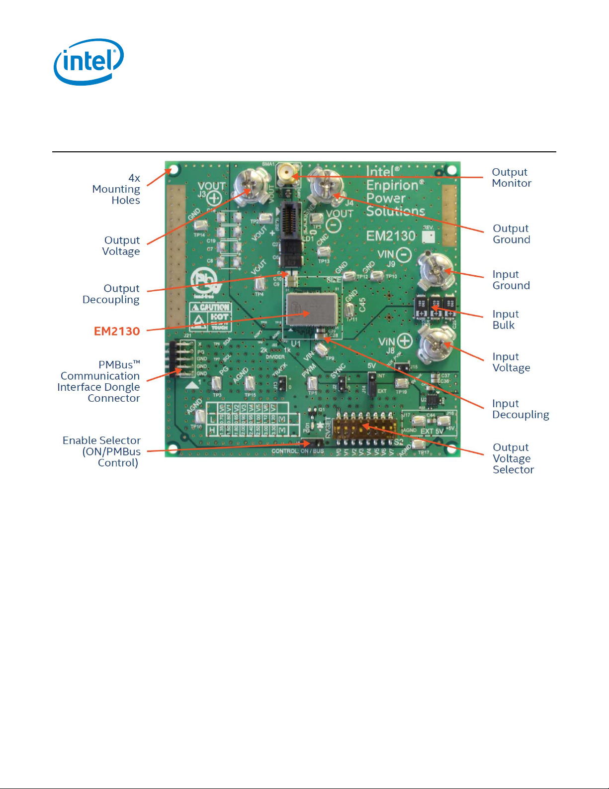
3. Evaluation Board Overview
Figure 1: EM2130 Evaluation Board Overview (View From Top)
Page 5
User Guide | Intel® Enpirion® Power Solutions
EM2130 Evaluation Board User Guide
5
4. Instructions
1) Connect the power supply
Set the Power Supply to 12V/10A.
Connect the power supply to the board (make sure that the power supply is OFF) with
two patch cables, not longer than 12 inches (30 cm). Using longer wires is possible,
provided that additional bulk is added to the board (the C45 through-hole capacitor
footprint is available for this purpose) and the input voltage is monitored at the board
level. Please use INPUT GROUND and INPUT VOLTAGE eyelet-terminated cables to
connect the power.
Please observe the correct polarity.
CAUTION: Incorrect polarity of the power supply may cause permanent
board damage!
CAUTION: Power supply voltage above 20V may cause permanent board
damage!
2) Connect the load
Connect the load to the OUTPUT GROUND and OUTPUT voltage with patch cables, no
longer than 12 inches (30 cm).
Please observe the correct polarity.
3) Check jumper settings
The board will arrive with one jumper on the J6 (BUS – enabling control through PMBUS),
one jumper on J14 (INT – this enables the on-board 5V power supply) and one jumper
on J15 (AUX_PVIN – this biases the 5V on board DC-DC converter). If an auxiliary 5V
power supply is needed (connected between J16 (+) and J17 (-)), J14 should be placed
across the “EXT” position while J15 can be removed.
Although “TRACK” and “SYNC” use 100 mils headers, they are NOT to be shorted by
jumpers.
4) Connect the PMBUS GUI interface dongle
The USB Dongle can be inserted only in the correct position, with pin one towards GND.
All pins must be properly inserted.
Prerequisite: the latest GUI software must be installed on a Windows PC.
Page 6

User Guide | Intel® Enpirion® Power Solutions
EM2130 Evaluation Board User Guide
6
5) Set the output voltage
Using the chart from the silkscreen, please select the desired output voltage, using ONLY
ONE switch ON. This setting will be read by the module when the part is powered on or
by PMBus command; changing the resistor on the fly will not have any effect.
6) Power-up the board
After all preparations above, the board should be ready to perform. If the GUI interface
dongle is not used, the jumper J6 should be moved to the “ON” position; else the jumper
J6 should be in the “BUS” position.
The voltage range (High/Low) is marked on the board, as shown in Figure 2:
Figure 2: “L” and “H” Jumper Table, Marked On The EM2130 Evaluation Board Silk Screen
For instruction on how to use the EM2130 GUI, please read “GUI User Guide.”
NOTE: To measure the Bode Plot of the DC-DC converter, R12 must be replaced with 50Ω resistor across which to inject the
signal, while TP18, TP20, TP8 and TP21 should be used to connect the probes of the phase analyzer.
Page 7

User Guide | Intel® Enpirion® Power Solutions
EM2130 Evaluation Board User Guide
7
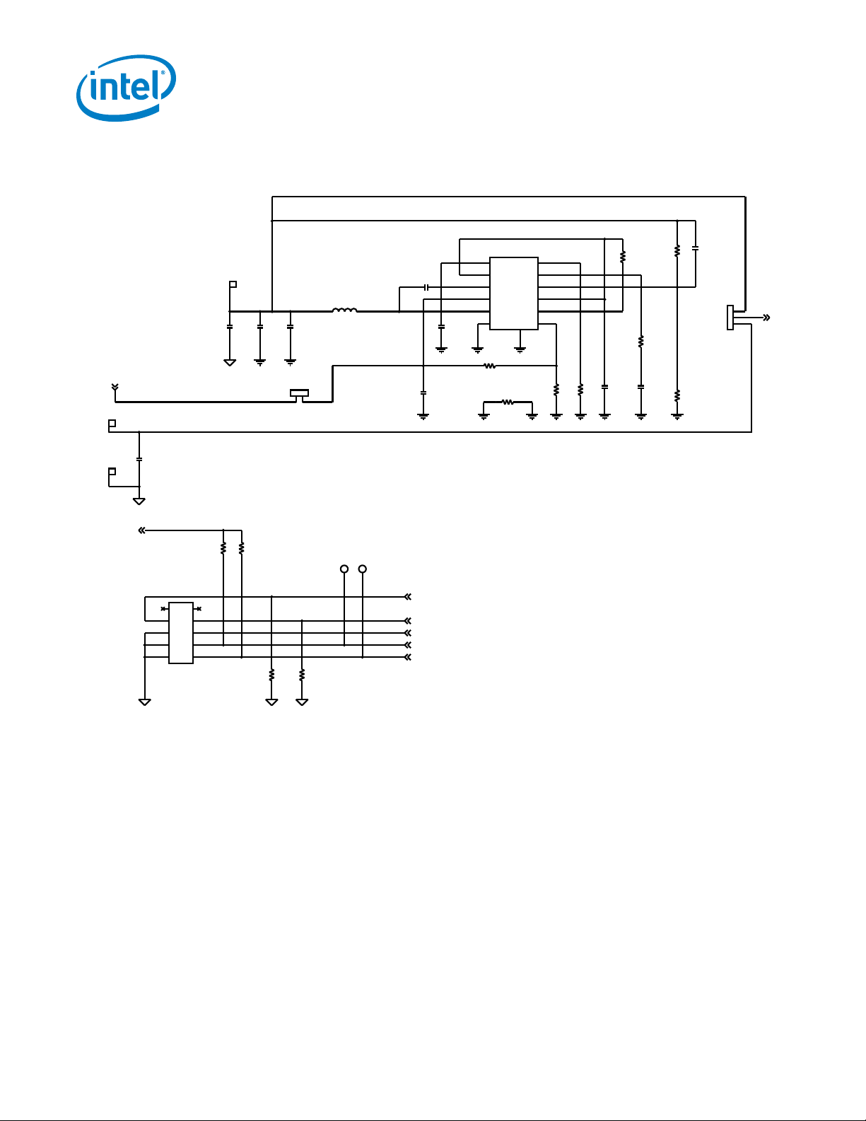
5. Evaluation Board Schematic
J4
U1
EM2130
AGN D
70
NC68
68
VSE NP
71
VSENN
72
VOU T
79
VOU T
3
VTRACK
77
ADDR1
7
VOU T
80
ADDR0
8
RTUNE
5
VOU T
2
VCCSEN
78
RVSE T
4
SCL15SDA
14
PGN D
32
VDD33
16
VCC
66
NC76
76
DGND
69
PWM
9
VOU T
81
VINSEN6VOU T
1
SMB ALERT13CONTR OL
12
PGOOD11SYNC
10
PGN D
33
PGN D
34
PGN D
35
PGN D
36
PGN D
37
PGN D
38
PGN D
39
PGN D
40
PGN D
42
PGN D
43
PGN D
44
PGN D
45
PGN D
46
PGN D
47
PGN D
48
PGN D
49
PGN D
50
PGN D
41
PGN D22PGN D
23
PGN D24PGN D25PGN D26PGN D
27
PGN D28PGN D
29
PGN D30PGN D
31
PGN D60PGN D
59
PGN D
58
PGN D57PGN D56PGN D
55
PGN D
54
PGN D53PGN D52PGN D
51
PVIN
61
PVIN
62
PVIN63PVIN
64
PVCC
65
NC67
67
NC7575NC7474NC73
73
PVIN
17
PVIN18PVIN19PVIN20PVIN
21
VOU T
100
VOU T
99
VOU T
98
VOU T
97
VOU T
96
VOU T
95
VOU T
94
VOU T
93
VOU T
92
VOU T
91
VOU T
90
VOU T
89
VOU T
88
VOU T
87
VOU T
86
VOU T
85
VOU T
84
VOU T
83
VOU T
82
PVIN_PAD
103
PGN D_PAD
104
AGND_PAD
102
VOUT _PAD
101
TP1
C6
+
C9
4x100uF
TP12
C10
J9
TP9
R15
1k/ 0.1%
C8
DNI
+
C14
S2
O
N
O
F
F
C7
DNI
+
R31
10.5k
C15
R34
3.74k
LD1
132
4
5
6
7
8
9
10
11
12
13
14
15
16
171819
20
Q1
2N7002
TP15
TP18
R48
DNI
R11
0
C31
DNI
C18
DNI
+
R35
2.43k
J22
J3
C23
5x100uF/20V
+
C29
10u
SMA1
C11
5x47uF
R32
8.66k
C1
47u
C28
TP17
C22
+
J2
TP11
C43
DNI
C27
R24
2k/ 0.1%
C45
DNI
+
R8
DNI
TP10
C12
R33
6.81k
R21
10k
C5
100u
C30
DNI
C26
3x22u
C2
2x470uF/2.5V/3mOhm
+
R12
0
TP8
CHF2
TP21
TP3
CHF1
2x470nF/25V
C19
DNI
+
R1
1k
J6
R3
1k
R28
23.2k
J13
R7
DNI
R22
3.3k
D1
R23
DNI
C40
+
R5
10k
C24
+
R17
2k/ 0.1%
R19
0
TP4
C4
R29
15.80k
C32
DNI
TP16
R18
DNI
TP20
CHF3
100nF/
25V
R20
392
TP5
TP
2
R6
DNI
FB1
C20
J8
C13
TP13
C25
+
R16
DNI
R13
11k/
0.1%
C16
DNI
+
TP14
C3
C21
2.2uF/
10V
R30
13.0k
C17
DNI
+
ADDR1
ADDR0
V_OUT
SYNC
VSENN
VSENP
VIN_SEN
V
V
SALE RT
RTUN E
RVSE T
PGOOD
CTRL
PVIN
VTRACK
VDD3V3
RTUNE
RVSE T
VTRACK
5V
VDD3V 3
5V
SCL SDA
PG
GND
PGN D
CTRL
VIN
GND
VOU T
PWM
AGN D
RTUNE
RVSET
0.7V
0.85V
0.8V
1.0V
0.95V
0.9V
1.2V
1.12V
TRACK
PGN D
AGN D
VOU T
Figure 3: Evaluation Board Schematic – Power
Page 8
User Guide | Intel® Enpirion® Power Solutions
EM2130 Evaluation Board User Guide
8
J16
R38
90.9k
TP7
R4
DNI
C42
1uF
R44
0
TP6
R37
10k
C35
47u
R2
DNI
J15
J14
L1
22uH
TP19
R42
3.32k
U2
ER3105QI
SS
1
SYNC
2
BOOT
3
PVIN
4
SW
5
PGND
6
FSW
12
COMP
11
FB
10
AVINO
09
POK
08
EN
07
EPAD
13
J17
C38
4.7nF
R45
12.4k
R41
10k
C36
47u
R60
15k
PMBUS
J21
1 2
3 4
5 6
7 8
9 10
C33
100pF
R40
100k
C34
0.1u
R61
15k
C41
10u
C44
10u
C37
47u
R43
133k
C39
470pF
5V0_A UX
5V_EXT
0 0 0 0 0 0
00
PVIN
5V
PGOOD
SALERT
CTRL
SCL
SDA
VDD3V3
5V
PVIN_5V
5VSEL
5V Bias Supply
500mA
GND
Ext_5V
PM Bus Components
Figure 4: Evaluation Board Schematic – AUX
Page 9

User Guide | Intel® Enpirion® Power Solutions
EM2130 Evaluation Board User Guide
9
6. Bill of Materials
Table 2: Bill of Materials
Type
Description
Qty.
BOM Ref Des
Mfr. Name
Capacitor
CAP CER 0.1UF X7R 0402 10V 10%
1
C34
Murata
Capacitor
CAP CER 4.7NF X7R 0402 25V 10%
1
C38
Murata
Capacitor
CAP CER 100UF 6.3V X5R 1206
5
C3,C4,C5,C9,C10
Kemet
Capacitor
CAP CER 47UF 6.3V X5R 0805
3
C35,C36,C37
Taiyo Yuden
Capacitor
CAP CER 47UF 6.3V X5R 1206
7
C1,C11,C12,C13,
C14,C15,C20
Murata
Capacitor
CAP CER 22UF 25V 10% X5R 1206
3
C26,C27,C28
Murata
Capacitor
CAP CER 2.2UF 16V 10% X6S 0402
1
C21
TDK
Capacitor
CAP CER 100PF 50V 5% NP0 0402
1
C33
Taiyo Yuden
Capacitor
CAP CER 1UF 25V 20% X5R 0402
1
C42
Taiyo Yuden
Capacitor
CAP CER 0.47UF 25V 20% X7R 0612
2
CHF1,CHF2
Murata
Capacitor
CAP CER 10UF 25V 10% X5R 0805
3
C29,C41,C44
Murata
Capacitor
CAP CER 470PF 25V X7R 10% 0402
1
C39
Vishay
Capacitor
CAP - POSCAP, 100UF, 20V, ESR=55 mΩ
5
C22,C23,C24,C25,
C40
Panasonic
Capacitor
CAP 100NF 25V 0805 FEED-THROUGH
1
CHF3
TDK
Capacitor
CAP ALUM POLY 470UF 20% 2.5V
2
C2,C6
Panasonic
Resistor
1K 1% 0805 CHIP RESISTOR 1/8W
1
R1
Panasonic
Resistor
RES 100K OHM 1/16W 1% 0402
1
R40
Panasonic
Resistor
RES ZERO OHM 1/10W 5% 0603
1
R19
Panasonic
Resistor
RESISTOR ZERO OHM 1/10W 5% 0402
3
R11,R12,R44
Panasonic
Resistor
RESISTOR 15K OHM 1/16W 5% 0402
2
R60
Stackpole
Electronics
Resistor
RES 90.9K OHM 1/16W 1% 0402
1
R38
Yageo
Resistor
RES 390 OHM 1/16W 0.1% 0603
1
R20
Panasonic
Resistor
RES 8.66K OHM 1/10W 1% 0603
1
R32
Panasonic
Resistor
RES 2.43K OHM 1/10W 1% 0603
1
R35
Vishay/Dale
Page 10

User Guide | Intel® Enpirion® Power Solutions
EM2130 Evaluation Board User Guide
10
Type
Description
Qty.
BOM Ref Des
Mfr. Name
Resistor
RES 133K OHM 1/10W 1% 0402
1
R43
Panasonic
Resistor
RES 3.32K OHM 1/10W 1% 0402
1
R42
Panasonic
Resistor
RES 12.4K OHM 1/10W 1% 0402
1
R45
Panasonic
Resistor
RES 1K OHM 1% 1/10W 0402
1
R3
Panasonic
Resistor
RES 11K OHM 1/16W 0.1% 0402
1
R13
Susumu
Resistor
RES - 6.81K OHM 0603 1/16W 1%
1
R33
Panasonic
Resistor
RES 1K OHM 1/16W 0.1% 0402
2
R15,R16
Susumu
Resistor
RES 2K OHM 1/16W 0.1% 0402
3
R17,R18,R24
Susumu
Resistor
RES 23.2K OHM 1/10W 1% 0603
1
R28
Vishay Dale
Resistor
RES - 3.74K OHM 0603 1/10W 1%
1
R34
Yageo
Resistor
RES 13K OHM 1/16W 1% 0603
1
R30
Yageo
Resistor
RES 3.3K OHM 1/16W 1% 0402
1
R22
Panasonic
Resistor
RES - 10.5K OHM, 1%,1/10W, 0603
1
R31
Panasonic
Resistor
RES 10K OHM 1/10W 1% 0402
4
R5,R21,R37,R41
Panasonic
Resistor
RES - 15.8K,0603,1%,
1
R29
KOA Speer
LED
LED GREEN CLEAR 0603
1
D1
LITE-ON INC
Inductor
INDUCTOR, 22UH, 1.3A,
1
L1
Taiyo Yuden
MOSFET
MOSFET N-CH 60V 300MA SOT23
1
Q1
Fairchild
Inductor
FERRITE BEAD 220 OHM 0402 1LN
1
FB1
Wurth
Electronik
Connector
INTEL 25A SLAM LOAD CONNECTOR
1
LD1
Samtec
Page 11

User Guide | Intel® Enpirion® Power Solutions
EM2130 Evaluation Board User Guide
11
7. Typical Performance
7.1 Pre-bias Monotonic Startup
Figure 5: Pre-bias Monotonic Startup, VIN = 12V, V
OUT
= 0.9V, Pre-bias = 0.6V
7.2 Transient Performance
Figure 6: Transient Performance, VIN = 12V, V
OUT
= 0.9V, ΔI
LOAD
= 0 to 15A (15A/µs)
CNTL
V
OUT
PWM
Load
V
OUT
Load
Page 12

User Guide | Intel® Enpirion® Power Solutions
EM2130 Evaluation Board User Guide
12
7.3 Ripple
Figure 7: Ripple, VIN = 12V, V
OUT
= 0.9V, I
LOAD
= 30A, fSW = 800 kHz
7.4 Efficiency
Figure 8: Efficiency Measured, VIN = 12V and Various V
OUT
65%
70%
75%
80%
85%
90%
95%
0 5 10 15 20 25 30
Efficiency (%)
Load Current (A)
0.7V 0.9V
1.0V 1.2V
1.8V 3.3V
V
OUT
Page 13

© 2017 Intel Corporation. All rights reserved. Intel, the Intel logo, Altera, Enpirion, and the Enpirion logo are trademarks of Intel Corporation in the US and/or
other countries. Other marks and brands may be claimed as the property of others. Intel warrants performance of its FPGA and semiconductor products to current
specifications in accordance with Intel's standard warranty, but reserves the right to make changes to any products and services at any time without notice. Intel
assumes no responsibility or liability arising out of the application or use of any information, product, or service describe d herein except as expressly agreed to
in writing by Intel. Intel customers are advised to obtain the latest version of device specifications before relying on any published information and before placing
orders for products or services.
8. Revision History
Revision
Number
Description
Revision Date
001
Initial release.
March 2017
Page 14

Mouser Electronics
Authorized Distributor
Click to View Pricing, Inventory, Delivery & Lifecycle Information:
Intel:
EVB-EM2130H01QI EVB-EM2130L01QI
 Loading...