

Page 1

Industrial Motherboard
EMB-H61A
EMB-H61A
Manual 3rd Ed.
January 2016
Page 2

Industrial Motherboard
EMB-H61A
Copyright Notice
This document is copyrighted, 2012. All rights are reserved. The
original manufacturer reserves the right to make improvements to the
products described in this manual at any time without notice.
No part of this manual may be reproduced, copied, translated, or
transmitted in any form or by any means without the prior written
permission of the original manufacturer. Information provided in this
manual is intended to be accurate and reliable. However, the original
manufacturer assumes no responsibility for its use, or for any infringements upon the rights of third parties that may result from its
use.
The material in this document is for product information only and is
subject to change without notice. While reasonable efforts have been
made in the preparation of this document to assure its accuracy, the
original manufacturer assumes no liabilities resulting from errors or
omissions in this document, or from the use of the information
contained herein.
The original manufacturer reserves the right to make changes in the
product design without notice to its users.
i
Page 3

Industrial Motherboard
EMB-H61A
Acknowledgments
All other products’ name or trademarks are properties of their
respective owners.
AMI is a trademark of American Megatrends Inc.
CompactFlash™ is a trademark of the Compact Flash
Association.
Intel® is a trademark of Intel® Corporation.
Microsoft Windows® is a registered trademark of Microsoft Corp.
ITE is a trademark of Integrated Technology Express, Inc.
IBM, PC/AT, PS/2, and VGA are trademarks of International
Business Machines Corporation.
SoundBlaster is a trademark of Creative Labs, Inc.
All other product names or trademarks are properties of their
respective owners.
ii
Page 4

Industrial Motherboard
EMB-H61A
Packing List
Before you begin installing your card, please make sure that the
following materials have been shipped:
1 Industrial Motherboard
1 SATA Cable
1 SATA Power Cable
1 Metal I/O Bracket
1 DVD-ROM for Manual (in PDF Format) and
Drivers
If any of these items should be missing or damaged, please
contact your distributor or sales representative immediately.
iii
Page 5

Industrial Motherboard
EMB-H61A
Contents
Chapter 1 General Information
1.1 Features.................................................................. 1-2
1.2 Specifications .......................................................... 1-3
Chapter 2 Quick Installation Guide
2.1 Safety Precautions .................................................. 2-2
2.2 Location of Connectors and Jumpers....................... 2-3
2.3 Mechanical Drawing ................................ ................ 2-5
2.4 List of Jumpers ........................................................ 2-7
2.5 List of Connectors ................................................... 2-7
2.6 Setting Jumpers ...................................................... 2-9
2.7 Clear CMOS (CLRTC1) ......................................... 2-10
2.8 LVDS Panel Voltage Selection (J1) ....................... 2-10
2.9 Inverter Voltage Selection (J2)............................... 2-10
2.10 Mode Selection for Back Light Control of Inverter (J3)
................................ ................................ ................... 2-10
2.11 AT/ATX Mode Selection (J4) ............................... 2-10
2.12 COM1 Ring/+5V/+12V Selection (J5)................... 2-11
2.13 Internal COM Serial Port Connector (COM2 ~ COM6)
................................ ................................ ................... 2-11
2.14 PS/2 Keyboard/Mouse Connector with Dock USB 2.0
Connector (CON19) .................................................... 2-11
2.15 1000Base-T Ethernet Connector with Dock USB 2.0
Connector (CON17/CON18) ........................................ 2-12
iv
Page 6

Industrial Motherboard
EMB-H61A
2.16 Digital I/O Connector (DIO) .................................. 2-12
2.17 Debug Connector (DEBUG)................................. 2-13
2.18 Front Panel Connector (F_PANEL) ...................... 2-13
2.19 Inverter Connector (INV)...................................... 2-14
2.20 LVDS Panel Signal Connector (LVDS) ................ 2-14
2.21 SATA Power Connector (PWR1) ......................... 2-15
2.22 FAN Connector (S_FAN1/S_FAN2) ..................... 2-15
2.23 BIOS Programmable Connector (SPI) ................. 2-16
2.24 Internal USB 2.0 Connector (USB1)..................... 2-16
Chapter 3 AMI BIOS Setup
3.1 System Test and Initialization. ................................. 3-2
3.2 AMI BIOS Setup ...................................................... 3-3
Chapter 4 Driver Installation
4.1 Installation ............................................................... 4-3
Appendix A Programming The Watchdog Timer
A.1 Watchdog Timer Initial Program ....................... A-2
Appendix B I/O Information
B.1 I/O Address Map .................................................. B-2
st
B.2 1
B.3 IRQ Mapping Chart .............................................. B-5
B.4 DMA Channel Assignments ................................ B-7
Appendix C Mating Connector
C.1 List of Mating Connectors and Cables ................. C-2
MB Memory Address Map ................................ B-4
v
Page 7

Industrial Motherboard
EMB-H61A
Appendix D Digital Input & Output
D.1 DIO Programming ............................................... D-2
D.2 Digital I/O Register.............................................. D-3
D.3 Digital I/O Sample Program ................................ D-4
vi
Page 8

Industrial Motherboard
EMB-H61A
Chapter
1
General
Information
Chapter 1 General Information 1- 1
Page 9

Industrial Motherboard
EMB-H61A
1.1 Features
Intel® Socket 1155 for 3rd Generation and Generation
Core™ i5/Core™ i3 Processors Up to 35W
2 x 204-pin Dual-Channel DDR3 1333/1066MHz DIMM
Up to 16GB
Intel® integrated Graphics Engine Supports Dual View by
VGA, DVI, HDMI, LVDS
Realtek PCI-Express Gigabit Ethernet x 2
SATA 3.0Gb/s x 2 & CF Socket x 1 (Supports Both
CF-SATA Card and CF Type 1)
USB 2.0 x 8 & COM x 6
PCI-Express 2.0 [x4 ] x 1 & Mini-PCIe Socket with SIM
Slot x 1 for mSATA support (Optional)
EuP/ErP Compliance
12V DC-in Support
TPM Module Support (Optional)
Chapter 1 General Information 1-2
Page 10

Industrial Motherboard
EMB-H61A
1-3
Processor
Intel® 2nd/3rd generation Core™ i5/i3
Processor, up to 35W
System Memory
204-pin dual-channel DDR3
1333/1066 SODIMM x 2, Max. 16
GB
Chipset
Intel® H61 (B3)
I/O Chipset
Fintek F81866D
Ethernet
Realtek 8111E for
10/100/1000Base-T, RJ-45 x 2
BIOS
AMI BIOS, 64MB ROM
Wake On LAN
Yes
Watchdog Timer
System reset: 1~255 steps
programmable
TPM
Optional
H/W Status Monitoring
Monitoring System Temperature,
Voltage, and Cooling Fan status
Expansion Interface
PCI-Express 2.0 [x4] x 1, Mini PCIe
x 1 (full size for mSATA support,
optional)
Battery
Lithium battery
Power Requirement
4-pin connector for DC12V input x 1;
CPU fan x 1, System fan with 4-pin
wafer x 1;
SATA power with 4-pin wafer x 1
Power Compliance
Compliant with EuP/ErP
Board Size
6.7”(L) x 6.7”(W) (170 mm x 170
mm)
1.2 Specifications
System
Chapter 1 General Information
Page 11

Industrial Motherboard
EMB-H61A
Gross Weight
1.1 lb (0.5 Kg)
Operating Temperature
32˚F~ 140˚F (0˚C ~ 60˚C)
Storage Temperature
-4˚F~ 158˚F (-20˚C ~ 70˚C)
Operating Humidity
10%~80% relative humidity,
non-condensing
EMI
CE/FCC Class A
Chipset
Integrated Graphics Processor
(CH7511B for eDP to dual 24-bit
LVDS)
Resolution
Shared System Memory up to
1748MB
Up to 1920x1200 @ 60Hz for
HDMI;
Up to 2048x1536 @ 75Hz for
RGB;
Up to 1920x1200 @ 60Hz for
DVI/LCD
LCD Interface
Dual 24-bit LVDS
Output Interface
Multi-VGA output support: HDMI/
RGB/ DVI-D/ LCD
Storage
SATA 3.0 Gb/s x 2, CF socket x 1
for CF-SATA support integrated
with PCIe to PATA bridge solution
Serial Port
RS-232 x 5, RS-232/422/485 x 1
(COM1)
USB
USB2.0 x 8 (5x2 pin header for
internal x 2, onboard Type A
connector x 6)
Display
I/O
Chapter 1 General Information 1-4
Page 12

Industrial Motherboard
EMB-H61A
1-5
Digital I/O
Supports 8-bit (4-in/ 4-out)
PS/2 Port
Keyboard/ Mouse x 1
Audio
Audio jack with BTX type x 3
(Mic-in, Line-out, Line-in)
Chapter 1 General Information
Page 13

Industrial Motherboard
EMB-H61A
Chapter
2
Quick
Installation
Guide
Chapter 2 Quick Installation Guide 2 - 1
Page 14
Industrial Motherboard
EMB-H61A
Always completely disconnect the power cord
from your board whenever you are working on
it. Do not make connections while the power is
on, because a sudden rush of power can
damage sensitive electronic components.
Always ground yourself to remove any static
charge before touching the board. Modern
electronic devices are very sensitive to static
electric charges. Use a grounding wrist strap at
all times. Place all electronic components on a
static-dissipative surface or in a static-shielded
bag when they are not in the chassis
2.1 Safety Precautions
Chapter 2 Quick Installation Guide 2 - 2
Page 15
Industrial Motherboard
EMB-H61A
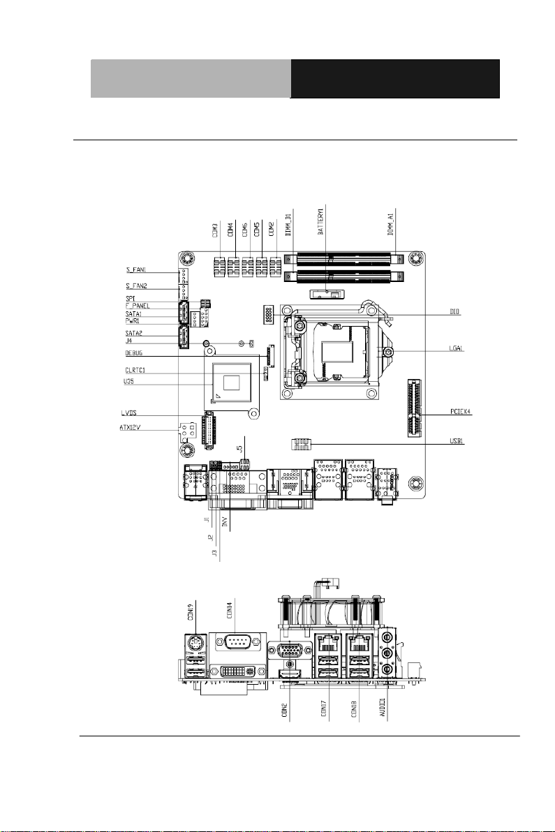
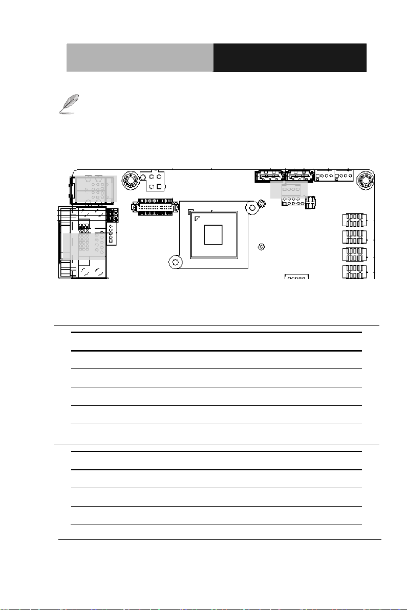
2.2 Location of Connectors and Jumpers
Component Side
Chapter 2 Quick Installation Guide 2 - 3
Page 16
Industrial Motherboard
EMB-H61A
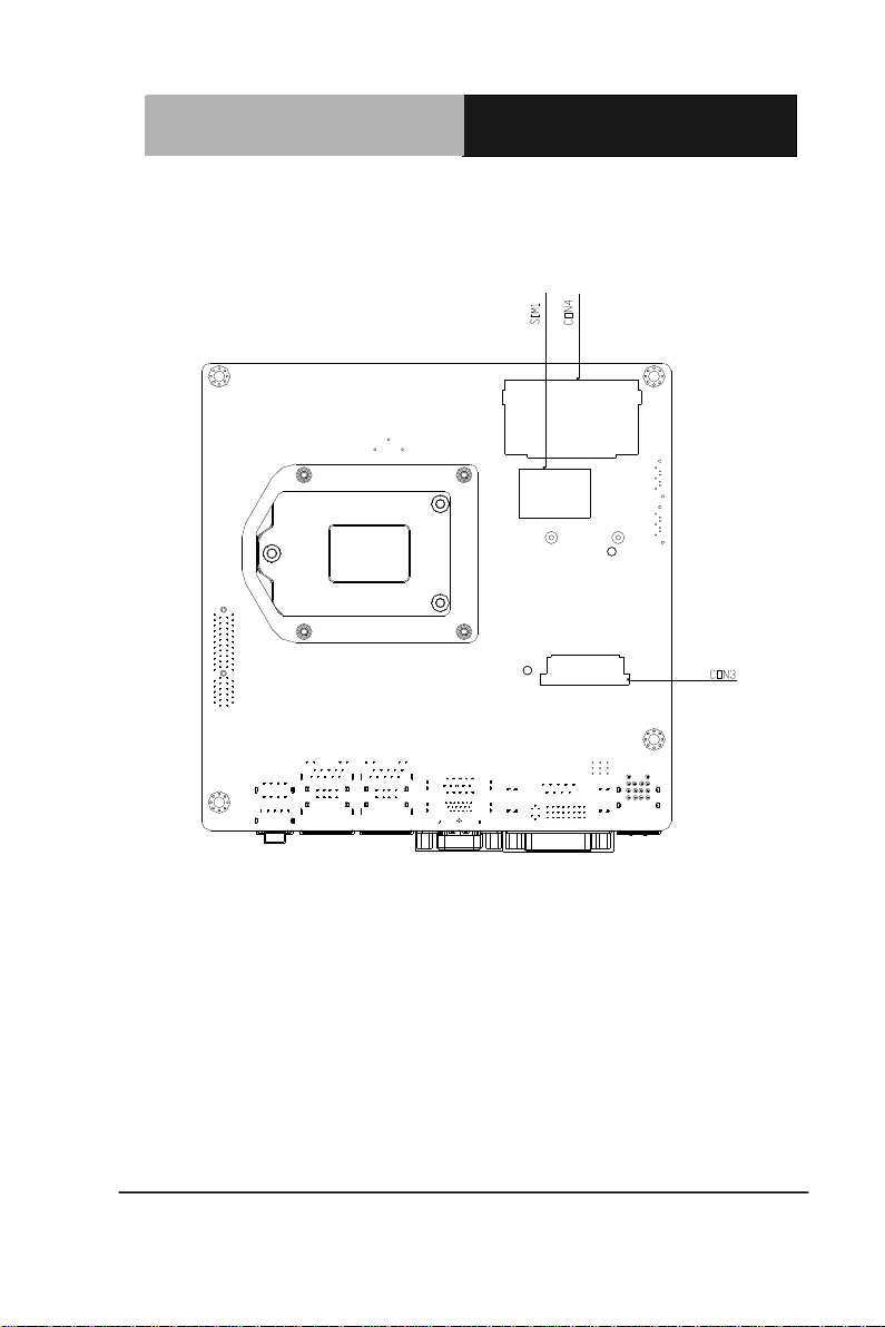
Solder Side
Chapter 2 Quick Installation Guide 2 - 4
Page 17
Industrial Motherboard
EMB-H61A
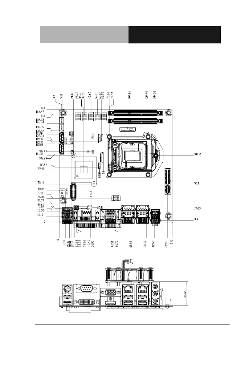
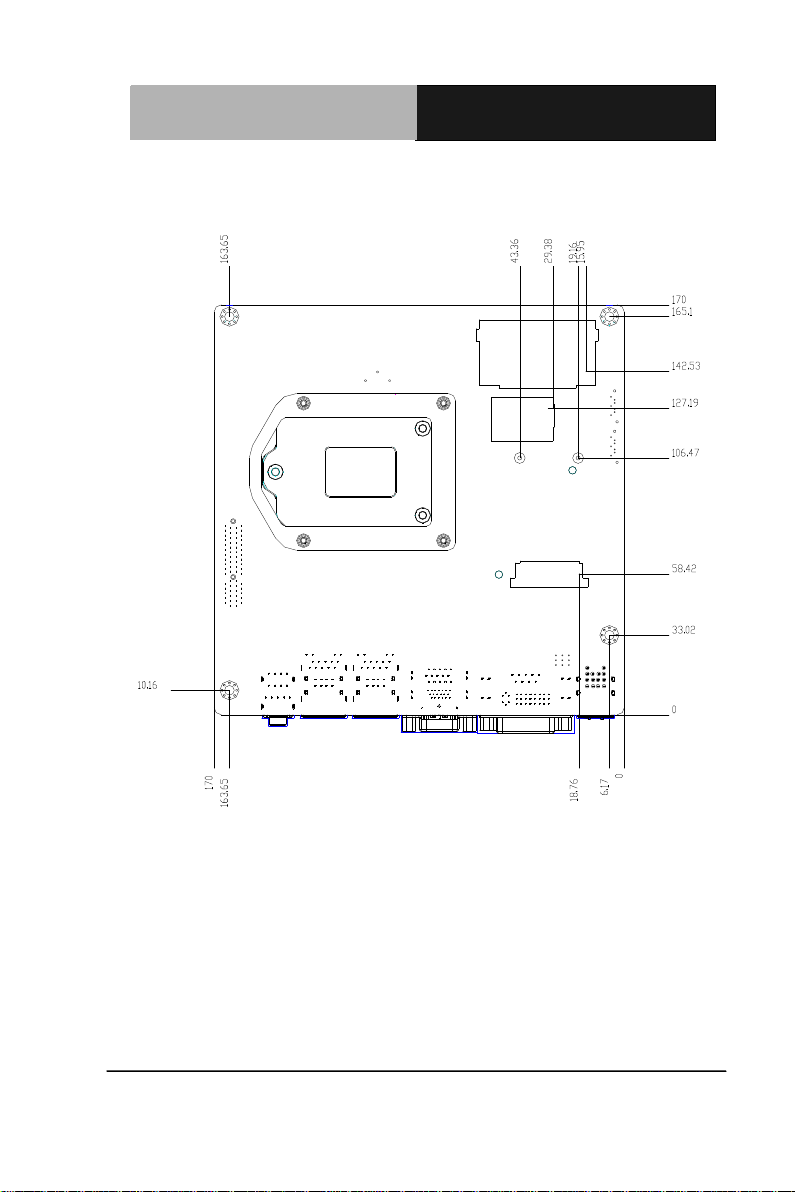
2.3 Mechanical Drawing
Component Side
Chapter 2 Quick Installation Guide 2 - 5
Page 18
Industrial Motherboard
EMB-H61A
Solder Side
Chapter 2 Quick Installation Guide 2 - 6
Page 19

Industrial Motherboard
EMB-H61A
Label
Function
CLRTC1
Clear CMOS
J1
LVDS Panel Voltage Selection
J2
Inverter Voltage Selection
J3
Mode Selection for Back Light Control of Inverter
J4
AT/ATX mode Selection
J5
COM1 Ring/+5V/+12V Selection
Label
Function
ATX12V
ATX 4P Power Connector
AUDIO1
Audio jack Connector
BATTERY1
RTC - Coin Battery Holder
COM2
COM2 Connector
COM3
COM3 Connector
COM4
COM4 Connector
COM5
COM5 Connector
COM6
COM6 Connector
2.4 List of Jumpers
The board has a number of jumpers that allow you to configure your
system to suit your application.
The table below shows the function of each of the board's jumpers:
2.5 List of Connectors
The board has a number of connectors that allow you to configure your
system to suit your application.
The table below shows the function of each of the board's connectors:
Chapter 2 Quick Installation Guide 2 - 7
Page 20

Industrial Motherboard
EMB-H61A
CON14
COM1 & DVI-D Connector
CON17
LAN1 and USB1/2 Connector
CON18
LAN2 and USB3/4 Connector
CON19
PS/2 KB&MS and USB5/6 Connector
CON2
D-Sub15_VGA Connector with HDMI
Connector
CON3
mini PCI-E Slot
CON4
Compact Flash Slot
DEBUG
Debug Connector
DIMM_A1
DIMM1 Slot
DIMM_B1
DIMM2 Slot
DIO
Digital I/O Connector
F_PANEL
Front Panel Connector
INV
Inverter Connector
LGA1
CPU Socket - LGA-1155P
LVDS
LVDS Panel Signal Connector
PCIEX4
PCI Express x4 Slot
PWR1
SATA Power Connector
S_FAN1
System FAN Connector
S_FAN2
System FAN Connector
SATA1
SATA II Connector
SATA2
SATA II Connector
SIM1
SIM Card Socket
SPI
BIOS Programmable Connector
USB1
Int. USB 2.0 Connector
Chapter 2 Quick Installation Guide 2 - 8
Page 21
Industrial Motherboard
EMB-H61A
1
2
3
Open Closed Closed 2-3
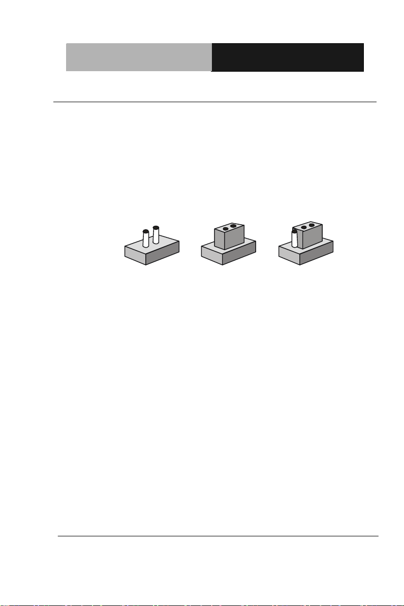
2.6 Setting Jumpers
You configure your card to match the needs of your application by
setting jumpers. A jumper is the simplest kind of electric switch. It
consists of two metal pins and a small metal clip (often protected by a
plastic cover) that slides over the pins to connect them. To “close” a
jumper you connect the pins with the clip.
To “open” a jumper you remove the clip. Sometimes a jumper will have
three pins, labeled 1, 2 and 3. In this case you would connect either
pins 1 and 2 or 2 and 3.
A pair of needle-nose pliers may be helpful when working with jumpers.
If you have any doubts about the best hardware configuration for your
application, contact your local distributor or sales representative before
you make any change.
Generally, you simply need a standard cable to make most
connections.
Chapter 2 Quick Installation Guide 2 - 9
Page 22

Industrial Motherboard
EMB-H61A
CLRTC1
Function
1-2
Protected (Default)
2-3
Clear
J1
Function
1-2
+5V
2-3
+3.3V (Default)
J2
Function
1-2
+12V
2-3
+5V (Default)
J3
Function
1-2
DC Voltage Control (Default)
2-3
PWM Control
J4
Function
1-2
AT Mode (Default)
Empty
ATX Mode
2.7 Clear CMOS (CLRTC1))
2.8 LVDS Panel Voltage Selection (J1)
2.9 Inverter Voltage Selection (J2)
2.10 Mode Selection for Back Light Control of Inverter (J3)
2.11 AT/ATX Mode Selection (J4)
Chapter 2 Quick Installation Guide 2 - 10
Page 23

Industrial Motherboard
EMB-H61A
J5
Function
1-2
+12V
3-4
+5V
5-6
Ring (Default)
Pin
Signal
Pin
Signal
1
DCD
2
RXD
3
TXD
4
DTR
5
GND
6
DSR
7
RTS
8
CTS
9
RI
10
(NC)
Pin
Signal
Pin
Signal
1
GND
2
USB2_DP1
3
USB2_DN1
4
+5V
5
GND
6
USB2_DP2
7
USB2_DN2
8
+5V 9 GND
10
KB_DATA
11
MS_DATA
12
+5V
13
KB_CLK
14
MS_CLK
15
GND
16
GND
2.12 COM1 Ring/+5V/+12V Selection (J5)
2.13 Internal COM Serial Port Connector (COM2 ~ COM6)
2.14 PS/2 Keyboard/Mouse Connector with Dock USB 2.0
Connector (CON19)
Chapter 2 Quick Installation Guide 2 - 11
Page 24

Industrial Motherboard
EMB-H61A
17
GND
18
GND
Pin
Signal
Pin
Signal
1
+5V 2 USB2_DN2
3
USB2_DP2
4
GND
5
+5V 6 USB2_DN1
7
USB2_DP1
8
GND
9
LAN_CTR
10
LAN_MDI_DP0
11
LAN_MDI_DN0
12
LAN_MDI_DP1
13
LAN_MDI_DN1
14
LAN_MDI_DP2
15
LAN_MDI_DN2
16
LAN_MDI_DP3
17
LAN_MDI_DN3
18
GND
19
LAN_LED_ACT
20
LAN_LED_ACT#
21
LAN_LED_LINK100#
22
LAN_LED_LINK1000#
23
GND
24
GND
25
GND
26
GND
27
GND
28
GND
29
GND
30
GND
Pin
Signal
Pin
Signal
1
DIO_I#1 (DIO_P#1)
2
DIO_I#2 (DIO_P#2)
3
DIO_I#3 (DIO_P#3)
4
DIO_I#4 (DIO_P#4)
5
DIO_O#1 (DIO_P#5)
6
DIO_O#2 (DIO_P#6)
2.15 1000Base-T Ethernet Connector with Dock USB 2.0 Connector
(CON17/CON18)
2.16 Digital I/O Connector (DIO)
Chapter 2 Quick Installation Guide 2 - 12
Page 25

Industrial Motherboard
EMB-H61A
7
DIO_O#3 (DIO_P#7)
8
DIO_O#4 (DIO_P#8)
9
+5V
10
GND
Pin
Signal
1
LPC_AD0
2
LPC_AD1
3
LPC_AD2
4
LPC_AD3
5
+3.3V
6
LPC_FRAME#
7
PLTRST#
8
GND
9
CLK_33M_LPC
10
LPC_DRQ#0
11
LPC_DRQ#1
12
SERIRQ#
Pin
Signal
Pin
Signal
1
HDLED+
2
PLED+
3
HDLED-
4
PLED-
5
GND
6
PANSWH#
7
HWRST#
8
GND
9
(NC)
10
(kill pin)
2.17 Debug Connector (DEBUG)
2.18 Front Panel Connector (F_PANEL)
Chapter 2 Quick Installation Guide 2 - 13
Page 26

Industrial Motherboard
EMB-H61A
Pin
Signal
1
Inverter VCC
3
Back Light Control
5
GND
7
GND
9
Back Light Enable
Pin
Signal
Pin
Signal
1
LVDS1_CLK-
2
LVDS1_CLK+
3
LVDS VCC
4
GND
5
LVDS1_D3-
6
LVDS1_D3+
7
LVDS1_D2-
8
LVDS1_D2+
9
LVDS1_D1-
10
LVDS1_D1+
11
LVDS1_D0-
12
LVDS1_D0+
13
EDID_Data
14
EDID_Clk
15
LVDS0_D3-
16
LVDS0_D3+
17
LVDS0_D2-
18
LVDS0_D2+
19
LVDS0_D1-
20
LVDS0_D1+
21
LVDS0_D0-
22
LVDS0_D0+
23
LVDS VCC
24
GND
25
LVDS0_CLK-
26
LVDS0_CLK+
27
LVDS VCC
28
GND
29
LVDS Panel Enable
30
Backlight Control for DC mode
2.19 Inverter Connector (INV)
2.20 LVDS Panel Signal Connector (LVDS)
Chapter 2 Quick Installation Guide 2 - 14
Page 27
Industrial Motherboard
EMB-H61A
NOTE: LVDS connector Vendor: PINREX; Model: 712-76-30GWR8.
Pin
Signal
1
+5V
2
GND
3
GND
4
+12V
Pin
Signal
1
PWM
2
SENSE
3
VCC
SATA
KB&MS
USB
COM
DVI-D
Please refer the drawing below, notice the location of PIN1, PIN2, PIN29 and
PIN30. KB&MS
29
1
230
2.21 SATA Power Connector (PWR1)
2.22 FAN Connector (S_FAN1/S_FAN2)
Chapter 2 Quick Installation Guide 2 - 15
Page 28

Industrial Motherboard
EMB-H61A
4
GND
4BPin
25BSignal
Pin
5BSignal
1
+V3.3SPI
2
GND
3
SPI_CS#
4
SPI_CLK
5
SPI_MISO
6
SPI_MOSI
7
(NC)
8
(NC)
Pin
Signal
Pin
Signal
1
+5V 2 GND
3
USB2_DN1
4
GND
5
USB2_DP1
6
USB2_DP2
7
GND
8
USB2_DN2
9
GND
10
+5V
2.23 BIOS Programmable Connector (SPI)
2.24 Internal USB 2.0 Connector (USB1)
Chapter 2 Quick Installation Guide 2 - 16
Page 29

Industrial Motherboard
EMB-H61A
Chapter
3
AMI
BIOS Setup
Chapter 3 AMI BIOS Setup 3-1
Page 30

Industrial Motherboard
EMB-H61A
3.1 System Test and Initialization
These routines test and initialize board hardware. If the routines
encounter an error during the tests, you will either hear a few short
beeps or see an error message on the screen. There are two kinds
of errors: fatal and non-fatal. The system can usually continue the
boot up sequence with non-fatal errors.
System configuration verification
These routines check the current system configuration against the
values stored in the CMOS memory. If they do not match, the
program outputs an error message. You will then need to run the
BIOS setup program to set the configuration information in memory.
There are three situations in which you will need to change the
CMOS settings:
1. You are starting your system for the first time
2. You have changed the hardware attached to your system
3. The CMOS memory has lost power and the configuration
information has been erased.
The EMB-H61A CMOS memory has an integral lithium battery
backup for data retention. However, you will need to replace the
complete unit when it runs down.
Chapter 3 AMI BIOS Setup 3-2
Page 31

Industrial Motherboard
EMB-H61A
3.2 AMI BIOS Setup
AMI BIOS ROM has a built-in Setup program that allows users to
modify the basic system configuration. This type of information is
stored in battery-backed CMOS RAM so that it retains the Setup
information when the power is turned off.
Entering Setup
Power on the computer and press <Del> or <F2> immediately. This
will allow you to enter Setup.
Main
Set the date, use tab to switch between date elements.
Advanced
Advanced BIOS Features Setup including TPM, ACPI, etc.
Chipset
host bridge parameters.
Boot
Enables/disable quiet boot option.
Security
Set setup administrator password.
Save&Exit
Exit system setup after saving the changes.
Chapter 3 AMI BIOS Setup 3-3
Page 32

Industrial Motherboard
EMB-H61A
Setup Menu
Setup submenu: Main
Setup submenu: Advanced
Chapter 3 AMI BIOS Setup 3-4
Page 33

Industrial Motherboard
EMB-H61A
Suspend mode
S1 (CPU Stop Clock)
S3 (Suspend to
RAM)
Optimal Default, Failsafe
Default
Select the ACPI state used for System Suspend
ACPI Settings
Options summary :
Chapter 3 AMI BIOS Setup 3-5
Page 34

Industrial Motherboard
EMB-H61A
Security
Device Support
Disabled
Optimal Default, Failsafe
Default
Enabled
En/Disable TPM support.
TPM State
Disabled
Optimal Default, Failsafe
Default
Enabled
En/Disable TPM State.
Pending
Operation
None
Optimal Default, Failsafe
Default
Trusted Computing
Options summary:
Chapter 3 AMI BIOS Setup 3-6
Page 35

Industrial Motherboard
EMB-H61A
Enable Take
Ownership
Disable Take
Ownership
TPM Clear
Select one-time TPM operation. Item value returns to ‘None’ after
next POST.
CPU Configuration
Chapter 3 AMI BIOS Setup 3-7
Page 36

Industrial Motherboard
EMB-H61A
Hyper-Threading
Disabled
Enabled
Optimal Default, Failsafe
Default
En/Disable CPU Hyper-Threading function
Intel
Virtualization
Technology
Disabled
Optimal Default, Failsafe
Default
Enabled
En/Disable Intel VT-x function
Options summary :
Digital IO Configuration
Chapter 3 AMI BIOS Setup 3-8
Page 37

Industrial Motherboard
EMB-H61A
DIO_P# 1-4
Input
Optimal Default, Failsafe
Default
Output
Set GPIO as Input or Output
DIO_P# 5-8
Input
Output
Optimal Default, Failsafe
Default
Set GPIO as Input or Output
DIO_P# 1-8
Direction
Low
High
Optimal Default, Failsafe
Default
Set GPIO Output as Hi or Low.
Options summary :
Chapter 3 AMI BIOS Setup 3-9
Page 38

Industrial Motherboard
EMB-H61A
SATA Configuration (IDE)
SATA Configuration (AHCI)
Chapter 3 AMI BIOS Setup 3-10
Page 39

Industrial Motherboard
EMB-H61A
SATA#1 IDE
Configuration
Disabled
Default
Enabled
Compatible: Configure SATA controller #1 as a legacy compatible
controller.
Enhanced: Configure SATA controller #1 as a Intel enhanced
controller.
SATA Mode
IDE
AHCI
Default
IDE: Configure SATA controllers as legacy IDE
AHCI: Configure SATA controllers to operate in AHCI mode
Hot Plug
Disabled
Optimal Default, Failsafe
Default
Enabled
En/Disable Hot Plug feature.
Options summary :
Chapter 3 AMI BIOS Setup 3-11
Page 40

Industrial Motherboard
EMB-H61A
Legacy USB Support
Enabled
Optimal Default, Failsafe
Default
Disabled
Auto
Enables BIOS Support for Legacy USB Support. When enabled,
USB can be functional in legacy environment like DOS.
AUTO option disables legacy support if no USB devices are
connected
Device Name
(Emulation Type)
Auto
Optimal Default, Failsafe
Default
USB Configuration
Options summary:
Chapter 3 AMI BIOS Setup 3-12
Page 41
Industrial Motherboard
EMB-H61A
Floppy
Forced FDD
Hard Disk
CDROM
If Auto. USB devices less than 530MB will be emulated as Floppy
and remaining as Floppy and remaining as hard drive. Forced FDD
option can be used to force a HDD formatted drive to boot as
FDD(Ex. ZIP drive)
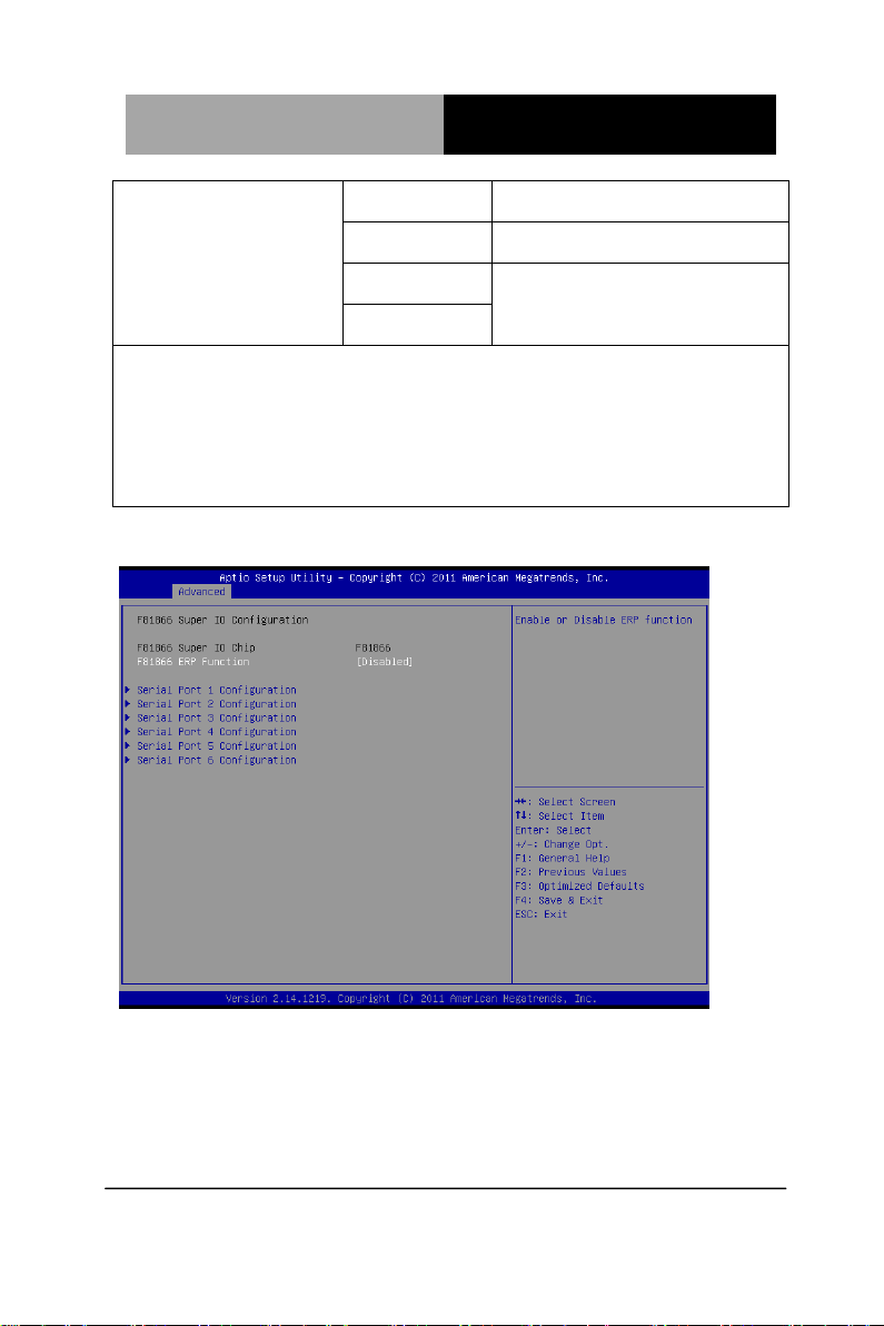
F81866 Supoer IO Configuration
Chapter 3 AMI BIOS Setup 3-13
Page 42

Industrial Motherboard
EMB-H61A
Serial Port Configuration
Chapter 3 AMI BIOS Setup 3-14
Page 43
Industrial Motherboard
EMB-H61A
F81866 ERP Function
Disabled
Default
Enabled
Enable or Disable ERP function.
Serial Port
Disabled
Enabled
Default
Allows BIOS to En/Disable correspond serial port.
Device Mode
RS232
Default
RS422
RS485
Select working model.
Change Settings
(Serial Port 1)
Auto
Default
IO=3F8h; IRQ=4;
IO=3F8h; IRQ=3,4;
IO=2F8h; IRQ=3,4;
IO=3E8h;
IRQ=10,11;
IO=2E8h;
IRQ=10,11
Allows BIOS to Select Serial Port resource.
Change Settings
(Serial Port 2)
Auto
Default
IO=2F8h; IRQ=3;
IO=3F8h; IRQ=3,4;
IO=2F8h; IRQ=3,4;
Options summary :
Chapter 3 AMI BIOS Setup 3-15
Page 44

Industrial Motherboard
EMB-H61A
IO=3E8h;
IRQ=10,11;
IO=2E8h;
IRQ=10,11
Allows BIOS to Select Serial Port resource.
Change Settings
(Serial Port 3)
Auto
Default
IO=3E8h;
IRQ=10,11;
IO=2E8h;
IRQ=10,11;
IO=2D0h;
IRQ=10,11;
IO=2D8h;
IRQ=10,11
Allows BIOS to Select Serial Port resource.
Change Settings
(Serial Port 4)
Auto
Default
IO=2E8h;
IRQ=10,11;
IO=3E8h;
IRQ=10,11;
IO=2D0h;
IRQ=10,11;
IO=2D8h;
IRQ=10,11;
Chapter 3 AMI BIOS Setup 3-16
Page 45

Industrial Motherboard
EMB-H61A
Allows BIOS to Select Serial Port resource.
Change Settings
(Serial Port 5)
Auto
Default
IO=2D0h;
IRQ=10,11;
IO=3E8h;
IRQ=10,11;
IO=2E8h;
IRQ=10,11;
IO=2D8h;
IRQ=10,11
Allows BIOS to Select Serial Port resource.
Change Settings
(Serial Port 6)
Auto
Default
IO=2D8h;
IRQ=10,11
IO=3E8h;
IRQ=10,11;
IO=2E8h;
IRQ=10,11;
IO=2D8h;
IRQ=10,11
Chapter 3 AMI BIOS Setup 3-17
Page 46
Industrial Motherboard
EMB-H61A
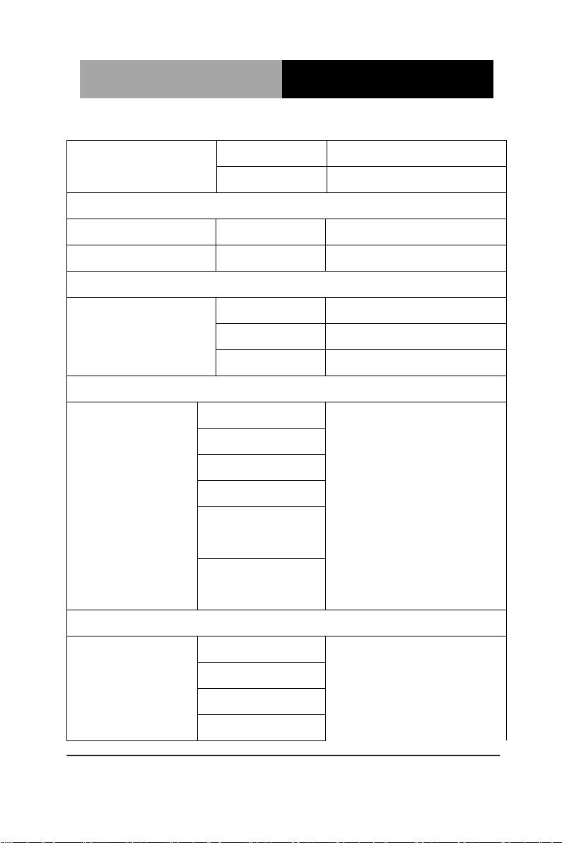
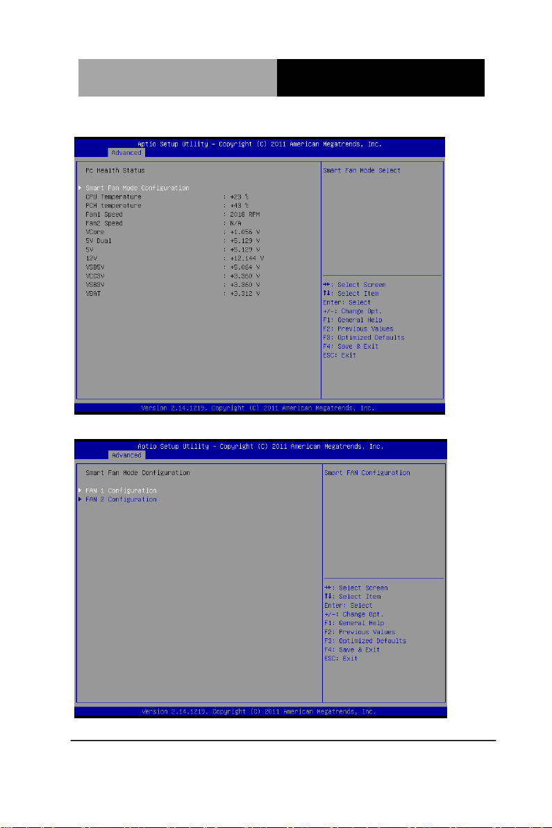
On-Module H/W Monitor
Smart Fan Mode Configuration
Chapter 3 AMI BIOS Setup 3-18
Page 47

Industrial Motherboard
EMB-H61A
SYS/CPU Smart Fan
Control
Auto by RPM
Default
Auto by Duty-Cycle
Manual by RPM
Manual by
Duty-Cycle
Select CPU Smart FAN mode
Auto by RPM: Automatically controlling the fan to maintain target
Fan Speed.
Auto by Duty-Cycle: Automatically controlling the fan to maintain
target temperature.
Manual by RPM: Manually controlling the fan with a given Fan
Speed.
Manual by Duty-Cycle: Manually controlling the fan with a given
control PWM.
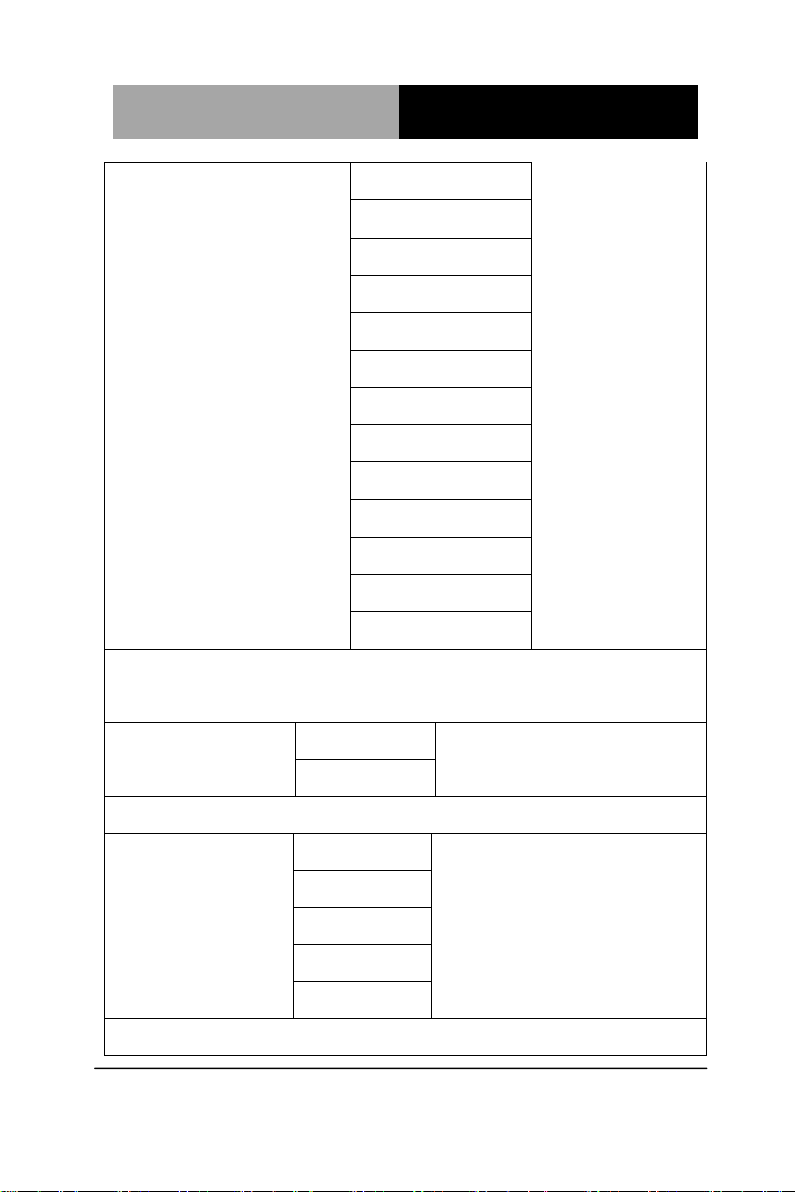
Target Temp. Sensor
CPU Temperature
Default
PCH Temperature
Options summary :
Chapter 3 AMI BIOS Setup 3-19
Page 48

Industrial Motherboard
EMB-H61A
Select target temperature source.
JMB36X ATA Controller Configuration
Setup submenu: Chipset
Chapter 3 AMI BIOS Setup 3-20
Page 49

Industrial Motherboard
EMB-H61A
PCH-IO Configuration
Chapter 3 AMI BIOS Setup 3-21
Page 50

Industrial Motherboard
EMB-H61A
Azalia
Disabled
Enabled
Optimal Default, Failsafe
Default
Enabling/Disabling HD Audio controller.
Azalia internal HDMI
Codec
Disabled
Optimal Default, Failsafe
Default
Enabled
Enabling/Disabling internal HDMI codec.
Restore on AC
Power Loss
Power Off
Power On
Last State
Default
Select the action system to take when restoring from power loss.
Mini PCI-E Gen Speed
Gen1
Optimal Default, Failsafe
Default
Gen2
Select PCI Express Gen speed.
Options summary :
Chapter 3 AMI BIOS Setup 3-22
Page 51

Industrial Motherboard
EMB-H61A
VT-d
Disabled
Enabled
Default
En/Disable chipset Virtualization Technology function.
PCIE x 4 Gen Speed
Gen1
Optimal Default, Failsafe
Default
Gen2
Select PCI Express Gen speed.
System Agent (SA) Configuration
Options summary :
Chapter 3 AMI BIOS Setup 3-23
Page 52

Industrial Motherboard
EMB-H61A
Graphics Configuration
Chapter 3 AMI BIOS Setup 3-24
Page 53

Industrial Motherboard
EMB-H61A
Primary Display
Auto
Default
IGFX
PEG
Select which of IGFX/PEG Graphics device should be Primary
Display.
Internal Graphics
Auto
Default
Disable
Enable
Keep IGD enabled based on the setup options.
GTT Size
1MB
2MB
Default
Select the GTT Size.
Aperture Size
128MB
256MB
Default
512MB
Select the Aperture Size.
DVMT Pre-Allocated
32M
64M
Default
96M
128M
160M
192M
Options summary :
Chapter 3 AMI BIOS Setup 3-25
Page 54

Industrial Motherboard
EMB-H61A
224M
256M
288M
320M
352M
384M
416M
448M
480M
512M
1024M
Select DVMT 5.0 Pre-Allocated(Fixed) Graphics Memory size used
by the Internal Graphics Device.
Primary IGFX Boot Display
AUTO
Default
CRT
HDMI
LVDS
DVI
Select the Video Device which will be activated during POST. For
dual-display, select “Auto”. Note: The platform only supports single
display in legacy environment (DOS).
CH7511B Panel Type
640x480 18Bit
800x600 18Bit
1024x768 18Bit
Default
Chapter 3 AMI BIOS Setup 3-26
Page 55
Industrial Motherboard
EMB-H61A
640x480 24Bit
800x600 24Bit
1024x768 24Bit
1280x1024 48Bit
1600x1200 48Bit
800x480 18Bit
1280x768 18Bit
1280x768 24Bit
1366x768 24Bit
1440x900 48Bit
1920x1080 48Bit
1280x1024 18Bit
1280x1024 24Bit
Select LCD panel used by Internal Graphics Device by selecting the
appropriate setup item.
CH7511B Baclight
Control Mode
DC Mode
Default
PWM Mode
Select Ch7511B Backlight Control by DC or PWM Mode.
Brightness setting
100%
Default
75%
50%
25%
0% CH7511B Brightness Setting.
Chapter 3 AMI BIOS Setup 3-27
Page 56

Industrial Motherboard
EMB-H61A
Bootup NumLock
State
On
Default
Off Select the keyboard NumLock state.
Quiet Boot
Disabled
Default
Enabled
En/Disable showing boot logo.
Launch RTL8111E
PXE OpROM
Disabled
Default
Enabled
Enable or Disable Legacy Boot Option for RTL811E.
Setup submenu: Boot
Options summary :
Chapter 3 AMI BIOS Setup 3-28
Page 57

Industrial Motherboard
EMB-H61A
GateA20 Active
Upon Request
Default
Always
UPON REQUEST – GA20 can be disabled using BIOS services.
ALWAYS – do not allow disabling GA20; this option is useful when any
RT code is executed above 1MB.
Option ROM
Messages
Force BIOS
Default
Keep Current
Set display mode for Option ROM.
INT19 Trap Response
Immediate
Default
Postponed
BIOS reaction on INT19 trapping by Option ROM:
IMMEDIATE – execute the trap right away;
POSTPONED – execute the trap during legacy boot.
Chapter 3 AMI BIOS Setup 3-29
Page 58

Industrial Motherboard
EMB-H61A
Setup submenu: Security
Change User/Supervisor Password
You can install a Supervisor password, and if you install a
supervisor password, you can then install a user password. A user
password does not provide access to many of the features in the
Setup utility.
If you highlight these items and press Enter, a dialog box appears
which lets you enter a password. You can enter no more than six
letters or numbers. Press Enter after you have typed in the
password. A second dialog box asks you to retype the password
for confirmation. Press Enter after you have retyped it correctly.
The password is required at boot time, or when the user enters the
Setup utility.
Chapter 3 AMI BIOS Setup 3-30
Page 59

Industrial Motherboard
EMB-H61A
Removing the Password
Highlight this item and type in the current password. At the next
dialog box press Enter to disable password protection.
Setup submenu: Exit
Chapter 3 AMI BIOS Setup 3-31
Page 60

Industrial Motherboard
EMB-H61A
Chapter
4
Driver
Installation
Chapter 4 Driver Installation 4-1
Page 61

Industrial Motherboard
EMB-H61A
Follow the sequence below to install the drivers:
Step 1 – Install Chipset Driver
Step 2 – Install VGA Driver
Step 3 – Install LAN Driver
Step 4 – Install AUDIO Driver
Step 5 – Install RAID & AHCI Driver
Step 6 – Install ME Driver
Step 7 – Install TPM Driver
Step 8 – Install UART Driver
Please read following instructions for detailed installations.
Chapter 4 Driver Installation 4-2
Page 62

Industrial Motherboard
EMB-H61A
4.1 Installation:
Insert DVD-ROM into the DVD-ROM Drive. And install the drivers
from Step 1 to Step 8 in order.
Step 1 – Install Chipset Driver
1. Click on the Step1 - Chipset folder and then double click
on the infinst_autol.exe
2. Follow the instructions that the window shows
3. The system will help you to install the driver automatically
Step 2 – Install VGA Driver
1. Click on the Step 2 - VGA folder and select the OS your
system is
2. Double click on Setup.exe file located in each OS folder
3. Follow the instructions that the window shows
4. The system will help you to install the driver automatically
Step 3 – Install LAN Driver
1. Click on the Step 3 - LAN folder and select the OS your
system is
2. Double click on setup.exe file located in each OS folder
3. Follow the instructions that the window shows
4. The system will help you to install the driver automatically
Step 4 – Install AUDIO Driver
1. Click on the Step 4 - Audio folder and select the OS your
system is
Chapter4 Drivers Installation 4-3
Page 63

Industrial Motherboard
EMB-H61A
2. Double click on Setup.exe file located in each OS folder
3. Follow the instructions that the window shows
4. The system will help you to install the driver automatically
Step 5 – Install RAID & AHCI Driver
Please refer to Appendix D RAID & AHCI Settings
Step 6 – Install ME Driver
1. Click on the Step 7 - ME folder and double click on
setup.exe file
2. Follow the instructions that the window shows
3. The system will help you to install the driver automatically
Step 7 – Install TPM Driver
1. Click on the Step 8 - TPM folder and double click on
Setup.exe file
2. Follow the instructions that the window shows
3. The system will help you to install the driver automatically
Step 8 – Install UART Driver
Chapter 4 Driver Installation 4-4
Page 64

Industrial Motherboard
EMB-H61A
Chapter4 Drivers Installation 4-5
Page 65

Industrial Motherboard
EMB-H61A
Chapter 4 Driver Installation 4-6
Page 66

Industrial Motherboard
EMB-H61A
Chapter4 Drivers Installation 4-7
Page 67

Industrial Motherboard
EMB-H61A
Appendix
A
Programming the
Watchdog Timer
Appendix A Programming the Watchdog Timer A-1
Page 68

Industrial Motherboard
EMB-H61A
Table 1 : SuperIO relative register table
Default Value
Note
Index
0x2E(Note1)
SIO MB PnP Mode Index Register
0x2E or 0x4E
Data
0x2F(Note2)
SIO MB PnP Mode Data Register
0x2F or 0x4F
Table 2 : Watchdog relative register table
LDN
Register
BitNum
Value
Note
Timer
Counter
0x07(Note3)
0xF6(Note4)
(Note24)
Time of watchdog
timer
(0~255)
This register is byte
access
Counting
Unit
0x07(Note5)
0xF5(Note6)
3(Note7)
0(Note8)
Select time unit.
0: second
1: minute
Watchdog
Enable
0x07(Note9)
0xF5(Note10)
5(Note11)
1(Note12)
0: Disable
1: Enable
Timeout
Status
0x07(Note13)
0xF5(Note14)
6(Note15)
1
1: Clear timeout
status
Output
Mode
0x07(Note16)
0xF5(Note17)
4(Note18)
1(Note19)
Select WDTRST#
output mode
0: level
1: pulse
WDTRST
output
0x07(Note20)
0xFA(Note21)
0(Note22)
1(Note23)
Enable/Disable
time out output via
WDTRST#
0: Disable
1: Enable
A.1 Watchdog Timer Initial Program
Appendix A Programming the Watchdog Timer A-2
Page 69

Industrial Motherboard
EMB-H61A
************************************************************************************
// SuperIO relative definition (Please reference to Table 1)
#define byte SIOIndex //This parameter is represented from Note1
#define byte SIOData //This parameter is represented from Note2
#define void IOWriteByte(byte IOPort, byte Value);
#define byte IOReadByte(byte IOPort);
// Watch Dog relative definition (Please reference to Table 2)
#define byte TimerLDN //This parameter is represented from Note3
#define byte TimerReg //This parameter is represented from Note4
#define byte TimerVal // This parameter is represented from Note24
#define byte UnitLDN //This parameter is represented from Note5
#define byte UnitReg //This parameter is represented from Note6
#define byte UnitBit //This parameter is represented from Note7
#define byte UnitVal //This parameter is represented from Note8
#define byte EnableLDN //This parameter is represented from Note9
#define byte EnableReg //This parameter is represented from Note10
#define byte EnableBit //This parameter is represented from Note11
#define byte EnableVal //This parameter is represented from Note12
#define byte StatusLDN // This parameter is represented from Note13
#define byte StatusReg // This parameter is represented from Note14
#define byte StatusBit // This parameter is represented from Note15
#define byte ModeLDN // This parameter is represented from Note16
#define byte ModeReg // This parameter is represented from Note17
#define byte ModeBit // This parameter is represented from Note18
#define byte ModeVal // This parameter is represented from Note19
#define byte WDTRstLDN // This parameter is represented from Note20
#define byte WDTRstReg // This parameter is represented from Note21
#define byte WDTRstBit // This parameter is represented from Note22
#define byte WDTRstVal // This parameter is represented from Note23
************************************************************************************
Appendix A Programming the Watchdog Timer A-3
Page 70

Industrial Motherboard
EMB-H61A
************************************************************************************
VOID Main(){
// Procedure : AaeonWDTConfig
// (byte)Timer : Time of WDT timer.(0x00~0xFF)
// (boolean)Unit : Select time unit(0: second, 1: minute).
AaeonWDTConfig();
// Procedure : AaeonWDTEnable
// This procudure will enable the WDT counting.
AaeonWDTEnable();
}
************************************************************************************
Appendix A Programming the Watchdog Timer A-4
Page 71

Industrial Motherboard
EMB-H61A
************************************************************************************
// Procedure : AaeonWDTEnable
VOID AaeonWDTEnable (){
WDTEnableDisable(EnableLDN, EnableReg, EnableBit, 1);
}
// Procedure : AaeonWDTConfig
VOID AaeonWDTConfig (){
// Disable WDT counting
WDTEnableDisable(EnableLDN, EnableReg, EnableBit, 0);
// Clear Watchdog Timeout Status
WDTClearTimeoutStatus();
// WDT relative parameter setting
WDTParameterSetting();
}
VOID WDTEnableDisable(byte LDN, byte Register, byte BitNum, byte
Value){
SIOBitSet(LDN, Register, BitNum, Value);
}
VOID WDTParameterSetting(){
// Watchdog Timer counter setting
SIOByteSet(TimerLDN, TimerReg, TimerVal);
// WDT counting unit setting
SIOBitSet(UnitLDN, UnitReg, UnitBit, UnitVal);
// WDT output mode setting, level / pulse
SIOBitSet(ModeLDN, ModeReg, ModeBit, ModeVal);
// Watchdog timeout output via WDTRST#
SIOBitSet(WDTRstLDN, WDTRstReg, WDTRstBit, WDTRstVal);
}
VOID WDTClearTimeoutStatus(){
SIOBitSet(StatusLDN, StatusReg, StatusBit, 1);
}
************************************************************************************
Appendix A Programming the Watchdog Timer A-5
Page 72

Industrial Motherboard
EMB-H61A
************************************************************************************
VOID SIOEnterMBPnPMode(){
IOWriteByte(SIOIndex, 0x87);
IOWriteByte(SIOIndex, 0x87);
}
VOID SIOExitMBPnPMode(){
IOWriteByte(SIOIndex, 0xAA);
}
VOID SIOSelectLDN(byte LDN){
IOWriteByte(SIOIndex, 0x07); // SIO LDN Register Offset = 0x07
IOWriteByte(SIOData, LDN);
}
VOID SIOBitSet(byte LDN, byte Register, byte BitNum, byte Value){
Byte TmpValue;
SIOEnterMBPnPMode();
SIOSelectLDN(byte LDN);
IOWriteByte(SIOIndex, Register);
TmpValue = IOReadByte(SIOData);
TmpValue &= ~(1 << BitNum);
TmpValue |= (Value << BitNum);
IOWriteByte(SIOData, TmpValue);
SIOExitMBPnPMode();
}
VOID SIOByteSet(byte LDN, byte Register, byte Value){
SIOEnterMBPnPMode();
SIOSelectLDN(LDN);
IOWriteByte(SIOIndex, Register);
IOWriteByte(SIOData, Value);
SIOExitMBPnPMode();
}
************************************************************************************
Appendix A Programming the Watchdog Timer A-6
Page 73

Industrial Motherboard
EMB-H61A
Appendix
B
I/O Information
Appendix B I/O Information B - 1
Page 74

Industrial Motherboard
EMB-H61A
B.1 I/O Address Map
Appendix B I/O Information B - 2
Page 75

Industrial Motherboard
EMB-H61A
Appendix B I/O Information B - 3
Page 76

Industrial Motherboard
EMB-H61A
B.2 1st MB Memory Address Map
Appendix B I/O Information B - 4
Page 77

Industrial Motherboard
EMB-H61A
B.3 IRQ Mapping Chart
Appendix B I/O Information B - 5
Page 78

Industrial Motherboard
EMB-H61A
Appendix B I/O Information B - 6
Page 79

Industrial Motherboard
EMB-H61A
B.4 DMA Channel Assignments
Appendix B I/O Information B - 7
Page 80

Industrial Motherboard
EMB-H61A
Appendix
C
Mating Connector
Appendix C Mating Connector C - 1
Page 81

Industrial Motherboard
EMB-H61A
Connector
Label
Function
Mating Connector
Vendor
Model no
ATX12V
ATX 4P Power Connector
PINREX
740-41-04TWC0
AUDIO1
Audio jack Connector
FOXCONN
JA33331-2119-4F
BATTERY1
RTC - Coin Battery Holder
LOTES
KB7566BP5L
COM2
Int. COM2 RS-232 Serial
Port Connector
PINREX
52M-90-10GBE0
COM3
Int. COM2 RS-232 Serial
Port Connector
PINREX
52M-90-10GBE0
COM4
Int. COM2 RS-232 Serial
Port Connector
PINREX
52M-90-10GBE0
COM5
Int. COM2 RS-232 Serial
Port Connector
PINREX
52M-90-10GBE0
COM6
Int. COM2 RS-232 Serial
Port Connector
PINREX
52M-90-10GBE0
CON14
D-Sub9_Series Port
Connector with DVI-D
Connector
FOXCONN
QH11121-DBCH-4F
CON17
1000 Base-T Ethernet
Connector with Dock USB
2.0 Connector
FOXCONN
JFM38U1M-21GS-4F
CON18
1000 Base-T Ethernet
Connector with Dock USB
2.0 Connector
FOXCONN
JFM38U1M-21GS-4F
CON19
PS/2 Keyboard/Mouse
Connector with Dock USB
2.0 Connector
FOXCONN
UB11121-HSDB-4F
CON2
D-Sub15_VGA Connector
with HDMI Connector
FOXCONN
QJ11197-VES1-4F
CON3
mini PCI-E Slot
LOTES
AAA-PCI-073-K02
C.1 List of Mating Connectors and Cables
The table notes mating connectors and available cables.
Appendix C Mating Connector C - 2
Page 82

Industrial Motherboard
EMB-H61A
CON4
Compact Flash Slot
PROCONN
CFH050-A0-53G6
DEBUG
Debug Connector
ACES
87212-12G0
DIMM_A1
DIMM1 Slot
FOXCONN
ATNA291-AED-4F
DIMM_B1
DIMM2 Slot
FOXCONN
ATNA291-AED-4F
DIO
Digital I/O Connector
PINREX
52S-90-10GB00
F_PANEL
Front Panel Connector
PINREX
210-92-05GB02
INV
Inverter Connector
PINREX
721-81-05TW00
LGA1
CPU Socket - LGA-1155P
LOTES
ACA-ZIF-096-P07
LVDS
LVDS Panel Signal
Connector
PINREX
712-76-30GWR8
PCIEX4
PCI Express x4 Slot
LOTES
AAA-PCI-022-K15
PWR1
SATA Power Connector
HR
A2540WV-4P
S_FAN1
System FAN Connector
PINREX
744-81-04TG20
S_FAN2
System FAN Connector
PINREX
744-81-04TG20
SATA1
SATA II Connector
PINREX
770-83-07SV29
SATA2
SATA II Connector
PINREX
770-83-07SV29
SIM1
SIM Card Socket
HAMBURG
ICA-509
SPI
BIOS Programmable
Connector
PINREX
232-92-04GBEM
USB1
Int. USB 2.0 Connector
PINREX
222-97-05GBE1
Appendix C Mating Connector C - 3
Page 83

Industrial Motherboard
EMB-H61A
Appendix
D
Electrical Specifications
for I/O Ports
Appendix D Electrical Specifications for I/O Ports D-1
Page 84

Industrial Motherboard
EMB-H61A
D.1 DIO Programming
EMB-H61A utilizes FINTEK 81866 chipset as its Digital I/O
controller.
Below are the procedures to complete its configuration and the
AAEON initial watchdog timer program is also attached based on
which you can develop customized program to fit your application.
There are three steps to complete the configuration setup: (1) Enter
the MB PnP Mode; (2) Modify the data of configuration registers; (3)
Exit the MB PnP Mode. Undesired result may occur if the MB PnP
Mode is not exited normally.(These three steps are the same as
programming WDT)
Appendix D Electrical Specifications for I/O Ports D-2
Page 85

Industrial Motherboard
EMB-H61A
Table 1 : SuperIO relative register table
Default Value
Note
Index
0x2E(Note1)
SIO MB PnP Mode Index Register
0x2E or 0x4E
Data
0x2F(Note2)
SIO MB PnP Mode Data Register
0x2F or 0x4F
Table 2 : Digital Input relative register table
LDN
Register
BitNum
Value
Note
DIO-1 Pin Status
0x06(Note3)
0x8A(Note4)
0(Note5)
GPIO80
DIO-2 Pin Status
0x06(Note6)
0x8A(Note7)
1(Note8)
GPIO81
DIO-3 Pin Status
0x06(Note9)
0x8A(Note10)
2(Note11)
GPIO82
DIO-4 Pin Status
0x06(Note12)
0x8A(Note13)
3(Note14)
GPIO83
DIO-5 Pin Status
0x06(Note15)
0x8A(Note16)
4(Note17)
GPIO84
DIO-6 Pin Status
0x06(Note18)
0x8A(Note19)
5(Note20)
GPIO85
DIO-7 Pin Status
0x06(Note21)
0x8A(Note22)
6(Note23)
GPIO86
DIO-8 Pin Status
0x06(Note24)
0x8A(Note25)
7(Note26)
GPIO87
Table 3 : Digital Output relative register table
LDN
Register
BitNum
Value
Note
DIO-1 Output Data
0x06(Note27)
0x89(Note28)
0(Note29)
(Note30)
GPIO80
DIO-2 Output Data
0x06(Note31)
0x89(Note32)
1(Note33)
(Note34)
GPIO81
DIO-3 Output Data
0x06(Note35)
0x89(Note36)
2(Note37)
(Note38)
GPIO82
DIO-4 Output Data
0x06(Note39)
0x89(Note40)
3(Note41)
(Note42)
GPIO83
DIO-5 Output Data
0x06(Note43)
0x89(Note44)
4(Note45)
(Note46)
GPIO84
DIO-6 Output Data
0x06(Note47)
0x89(Note48)
5(Note49)
(Note50)
GPIO85
DIO-7 Output Data
0x06(Note51)
0x89(Note52)
6(Note53)
(Note54)
GPIO86
DIO-8 Output Data
0x06(Note55)
0x89(Note56)
7(Note57)
(Note58)
GPIO87
D.2 Digital I/O Register
Appendix D Electrical Specifications for I/O Ports D-3
Page 86

Industrial Motherboard
EMB-H61A
D.3 Digital I/O Sample Program
************************************************************************************
// SuperIO relative definition (Please reference to Table 1)
#define byte SIOIndex //This parameter is represented from Note1
#define byte SIOData //This parameter is represented from Note2
#define void IOWriteByte(byte IOPort, byte Value);
#define byte IOReadByte(byte IOPort);
// Digital Input Status relative definition (Please reference to Table 2)
#define byte DInput1LDN // This parameter is represented from Note3
#define byte DInput1Reg // This parameter is represented from Note4
#define byte DInput1Bit // This parameter is represented from Note5
#define byte DInput2LDN // This parameter is represented from Note6
#define byte DInput2Reg // This parameter is represented from Note7
#define byte DInput2Bit // This parameter is represented from Note8
#define byte DInput3LDN // This parameter is represented from Note9
#define byte DInput3Reg // This parameter is represented from Note10
#define byte DInput3Bit // This parameter is represented from Note11
#define byte DInput4LDN // This parameter is represented from Note12
#define byte DInput4Reg // This parameter is represented from Note13
#define byte DInput4Bit // This parameter is represented from Note14
#define byte DInput5LDN // This parameter is represented from Note15
#define byte DInput5Reg // This parameter is represented from Note16
#define byte DInput5Bit // This parameter is represented from Note17
#define byte DInput6LDN // This parameter is represented from Note18
#define byte DInput6Reg // This parameter is represented from Note19
#define byte DInput6Bit // This parameter is represented from Note20
#define byte DInput7LDN // This parameter is represented from Note21
#define byte DInput7Reg // This parameter is represented from Note22
#define byte DInput7Bit // This parameter is represented from Note23
#define byte DInput8LDN // This parameter is represented from Note24
#define byte DInput8Reg // This parameter is represented from Note25
#define byte DInput8Bit // This parameter is represented from Note26
************************************************************************************
Appendix D Electrical Specifications for I/O Ports D-4
Page 87

Industrial Motherboard
EMB-H61A
************************************************************************************
// Digital Output control relative definition (Please reference to Table 3)
#define byte DOutput1LDN // This parameter is represented from Note27
#define byte DOutput1Reg // This parameter is represented from Note28
#define byte DOutput1Bit // This parameter is represented from Note29
#define byte DOutput1Val // This parameter is represented from Note30
#define byte DOutput2LDN // This parameter is represented from Note31
#define byte DOutput2Reg // This parameter is represented from Note32
#define byte DOutput2Bit // This parameter is represented from Note33
#define byte DOutput2Val // This parameter is represented from Note34
#define byte DOutput3LDN // This parameter is represented from Note35
#define byte DOutput3Reg // This parameter is represented from Note36
#define byte DOutput3Bit // This parameter is represented from Note37
#define byte DOutput3Val // This parameter is represented from Note38
#define byte DOutput4LDN // This parameter is represented from Note39
#define byte DOutput4Reg // This parameter is represented from Note40
#define byte DOutput4Bit // This parameter is represented from Note41
#define byte DOutput4Val // This parameter is represented from Note42
#define byte DOutput5LDN // This parameter is represented from Note43
#define byte DOutput5Reg // This parameter is represented from Note44
#define byte DOutput5Bit // This parameter is represented from Note45
#define byte DOutput5Val // This parameter is represented from Note46
#define byte DOutput6LDN // This parameter is represented from Note47
#define byte DOutput6Reg // This parameter is represented from Note48
#define byte DOutput6Bit // This parameter is represented from Note49
#define byte DOutput6Val // This parameter is represented from Note50
#define byte DOutput7LDN // This parameter is represented from Note51
#define byte DOutput7Reg // This parameter is represented from Note52
#define byte DOutput7Bit // This parameter is represented from Note53
#define byte DOutput7Val // This parameter is represented from Note54
#define byte DOutput8LDN // This parameter is represented from Note55
#define byte DOutput8Reg // This parameter is represented from Note56
#define byte DOutput8Bit // This parameter is represented from Note57
#define byte DOutput8Val // This parameter is represented from Note58
************************************************************************************
Appendix D Electrical Specifications for I/O Ports D-5
Page 88

Industrial Motherboard
EMB-H61A
************************************************************************************
VOID Main(){
Boolean PinStatus ;
// Procedure : AaeonReadPinStatus
// Input :
// Example, Read Digital I/O Pin 3 status
// Output :
// InputStatus :
// 0: Digital I/O Pin level is low
// 1: Digital I/O Pin level is High
PinStatus = AaeonReadPinStatus(DInput3LDN, DInput3Reg, DInput3Bit);
// Procedure : AaeonSetOutputLevel
// Input :
// Example, Set Digital I/O Pin 6 level
AaeonSetOutputLevel(DOutput6LDN, DOutput6Reg, DOutput6Bit,
DOutput6Val);
}
************************************************************************************
Appendix D Electrical Specifications for I/O Ports D-6
Page 89

Industrial Motherboard
EMB-H61A
************************************************************************************
Boolean AaeonReadPinStatus(byte LDN, byte Register, byte BitNum){
Boolean PinStatus ;
PinStatus = SIOBitRead(LDN, Register, BitNum);
Return PinStatus ;
}
VOID AaeonSetOutputLevel(byte LDN, byte Register, byte BitNum,
byte Value){
ConfigToOutputMode(LDN, Register, BitNum);
SIOBitSet(LDN, Register, BitNum, Value);
}
************************************************************************************
Appendix D Electrical Specifications for I/O Ports D-7
Page 90

Industrial Motherboard
EMB-H61A
************************************************************************************
VOID SIOEnterMBPnPMode(){
IOWriteByte(SIOIndex, 0x87);
IOWriteByte(SIOIndex, 0x87);
}
VOID SIOExitMBPnPMode(){
IOWriteByte(SIOIndex, 0xAA);
}
VOID SIOSelectLDN(byte LDN){
IOWriteByte(SIOIndex, 0x07); // SIO LDN Register Offset = 0x07
IOWriteByte(SIOData, LDN);
}
VOID SIOBitSet(byte LDN, byte Register, byte BitNum, byte Value){
Byte TmpValue;
SIOEnterMBPnPMode();
SIOSelectLDN(byte LDN);
IOWriteByte(SIOIndex, Register);
TmpValue = IOReadByte(SIOData);
TmpValue &= ~(1 << BitNum);
TmpValue |= (Value << BitNum);
IOWriteByte(SIOData, TmpValue);
SIOExitMBPnPMode();
}
VOID SIOByteSet(byte LDN, byte Register, byte Value){
SIOEnterMBPnPMode();
SIOSelectLDN(LDN);
IOWriteByte(SIOIndex, Register);
IOWriteByte(SIOData, Value);
SIOExitMBPnPMode();
}
************************************************************************************
Appendix D Electrical Specifications for I/O Ports D-8
Page 91

Industrial Motherboard
EMB-H61A
************************************************************************************
Boolean SIOBitRead(byte LDN, byte Register, byte BitNum){
Byte TmpValue;
SIOEnterMBPnPMode();
SIOSelectLDN(LDN);
IOWriteByte(SIOIndex, Register);
TmpValue = IOReadByte(SIOData);
TmpValue &= (1 << BitNum);
SIOExitMBPnPMode();
If(TmpValue == 0)
Return 0;
Return 1;
}
VOID ConfigToOutputMode(byte LDN, byte Register, byte BitNum){
Byte TmpValue, OutputEnableReg;
OutputEnableReg = Register-1;
SIOEnterMBPnPMode();
SIOSelectLDN(LDN);
IOWriteByte(SIOIndex, OutputEnableReg);
TmpValue = IOReadByte(SIOData);
TmpValue |= (1 << BitNum);
IOWriteByte(SIOData, OutputEnableReg);
SIOExitMBPnPMode();
}
************************************************************************************
Appendix D Electrical Specifications for I/O Ports D-9
 Loading...