

Page 1

2nd Generation Intel® Core™ Processor Family Desktop
Specification Update
January 2011
Reference Number: 324643-001
Page 2

Legal Lines and Disclaimers
INFORMATION IN THIS DOCUMENT IS PROVIDED IN CONNECTION WITH INTEL PRODUCTS. NO LICENSE, EXPRESS OR IMPLIED, BY
ESTOPPEL OR OTHERWISE, TO ANY INTELLECTUAL PRO PERTY RIGHTS IS GRANTED BY THIS DOCUMENT. EXCEPT AS PROVIDED IN
INTEL'S TERMS AND CONDITIONS OF SALE FOR SUCH PRODUCTS, INTEL ASSUMES NO LIABILITY WHATSOEV ER, AND INTEL DISCLAIMS
ANY EXPRESS OR IMPLIED WARRANTY, RELATING TO SALE AND/OR USE OF INTEL PRODUCTS INCLUDING LIABILITY OR WARRANTIES
RELATING T O FITNESS FOR A PARTICULAR PURPOSE, MERCHANTABILITY, OR INFRINGEMENT OF ANY PATENT, COPYRIGHT OR OTHER
INTELLECTUAL PROPERTY RIGHT. Intel products are not intended for use in medical, life saving, life sust aining, critical control or safety systems, or
in nuclear facility applications.
Intel may make changes to specifications and product descriptions at any time, without notice.
Designers must not rely on the absence or characteristics of any features or instructions marked “reserved” or “un defined.” Intel reserves these for
future definition and shall have no responsibility whatsoever for conflicts or incompatibilities arising from future changes to them.
The processor may contain design defects or errors known as errata which may cause the product to deviate from published specifications. Current
characterized errata are available on request.
Contact your local Intel sales office or your distri butor to obtain the latest specifications and before placing your product order.
Intel processor numbers are not a measure of performance. Processor numbers differentiat e features within each processor family, not across
different processor families. See http://www.intel.com/products/processor_number for details. Over time processor numbers will increment based on
changes in clock, speed, cache, or other features, an d increment s are not inte nded to r epresent pro portional or quantit ative increases in a ny particular
feature. Current roadmap processor number progression is not necessarily representative of future roadmaps. See www.intel.com/products/
processor_number for details.
®
Active Management Technology requires the computer system to have an Intel(R) AMT-enabled chipset, network hardware and software, as
Intel
well as connection with a power source and a corporate network connection . Setu p req uires configu rat ion b y the purchaser and may require scripting
with the management console or further integration into existing security frameworks to enable certain functionality . I t may also require modifications
of implementation of new business processes. With regard to notebooks, Intel AMT may not be available or certain capabilities may be limited over a
host OS-based VPN or when connecting wirelessly, on battery power, sleeping, hibernating or powered off. For more information, see www.intel.com/
technology/platform-technology/intel-amt/
®
Trusted Execution Technology (Intel® TXT) requires a computer system with Intel® Virtualization Technology (Intel® Virtualization Technology
Intel
®
VT-x) and Intel® Virtualization Technology for Directed I/O (Intel® VT-d)), a Intel TXT-enabled processor, chipset, BIOS, Authenticated Code
(Intel
Modules and an Intel TXT-compatible measured launched environment (MLE). The MLE could consist of a virtual machine monitor, an OS or an
application. In addition, Intel TXT requires the system to contain a TPM v1.2, as defined by the Trusted Computing Group and specific software for
some uses. For more information, see http://www.intel.com/technology/security
®
Virtualization Technology requires a computer system with an enabled Intel® processor, BIOS, virtual machine monitor (VMM) and, for some
Intel
uses, certain computer system software enabled for it. Functionality, performance or other benefits will vary depending on hardware and software
configurations and may require a BIOS update. Software applications may not be compatible with all operating systems. Please check with your
application vendor.
®
* Intel
Turbo Boost Technology requires a PC with a processor with Intel Turbo Boost Technology capability. Intel Turbo Boost Technology
performance varies depending on hardware, software and overall system configuration. Check with your PC manufacturer on whether your system
delivers Intel Turbo Boost Technology. For more information, see http://www.intel.com/technology/turboboost
®
Intel
Hyper-threading Technology requires a computer system with a processor supporting HT Technology and an HT Technology-enabled chipset,
BIOS, and operating system. Performance will vary depending on the specific hardware and software you use. For more information including details
on which processors support HT Technology, see http://www.intel.com/info/hyperthreading.
64-bit computing on Intel architecture requires a computer system with a processor, chipset, BIOS, operating system, device drivers and applications
enabled for Intel
for more information.
®
64 architecture. Performance will vary depending on your hardware and software confi gurations. Consult with your system vendor
Copies of documents which have an order number and are referenced in this document, or other Intel literature may be obtained by visiting Intel's
website at http://www.intel.com.
Intel, Intel Core, Celeron, Pentium, Intel Xeon, Intel Atom, Intel SpeedStep, and the Intel logo are trademarks or registered trademarks of Intel
Corporation or its subsidiaries in the United States and other countries.
*Other names and brands may be claimed as the property of others.
Copyright © 2011, Intel Corporation. All Rights Reserved.
2
Specification Update
Page 3

Contents
Contents
Revision History...............................................................................................................5
Preface ..............................................................................................................................6
Summary Tables of Changes..........................................................................................8
Identification Information..............................................................................................12
Errata...............................................................................................................................14
Specification Changes...................................................................................................37
Specification Clarifications...........................................................................................38
Documentation Changes...............................................................................................39
§
Specification Update
3
Page 4

Contents
4
Specification Update
Page 5
Revision History
Revision Description Date
-001 Initial Release January 2011
Specification Update 5
Page 6

Preface
This document is an update to the specifications contained in the Affected Documents
table below. This document is a compilation of device and documentation errata,
specification clarifications and changes. It is intended for hardware system
manufacturers and software developers of applications, operating systems, or tools.
Information types defined in Nomenclature are consolidated into the specification
update and are no longer published in other documents.
This document may also contain information that was not previously published.
Affected Documents
nd
Generation Intel® Core™ Processor Family Desktop Datasheet, Volume 1 324641-001
2
nd
2
Generation Intel® Core™ Processor Family Desktop Datasheet, Volume 2 324642-001
Related Documents
AP-485, Intel® Processor Identification and the CPUID Instruction http://www.intel.com/
®
Intel
64 and IA-32 Architectures Software Developer’s Manual,
Volume 1: Basic Architecture
®
64 and IA-32 Architectures Software Developer’s Manual,
Intel
Volume 2A: Instruction Set Reference Manual A-M
®
64 and IA-32 Architectures Software Developer’s Manual,
Intel
Volume 2B: Instruction Se t Reference Manual N-Z
®
64 and IA-32 Architectures Software Developer’s Manual,
Intel
Volume 3A: System Programming Guide
®
64 and IA-32 Architectures Software Developer’s Manual,
Intel
Volume 3B: System Programming Guide
®
64 and IA-32 Intel Architecture Optimization Reference
Intel
Manual
®
Intel
64 and IA-32 Architectures Software Developer’s Manual
Documentation Changes
ACPI Specifications www.acpi.info
Document Title
Document Title
Document
Number
Document Number/
Location
design/processor/
applnots/241618.htm
http://www.intel.com/
products/processor/
manuals/index.htm
http://www.intel.com/
design/processor/
specupdt/252046.htm
6 Specification Update
Page 7

Nomenclature
Errata are design defects or errors. These may cause the processor behavior to
deviate from published specifications. Hardware and software designed to be used with
any given stepping must assume that all errata documented for that stepping are
present on all devices.
S-Spec Number is a five-digit code used to identify products. Products are
differentiated by their unique characteristics such as, core speed, L2 cache size,
package type, etc. as described in the processor identification information table. Read
all notes associated with each S-Spec number.
Specification Changes are modifications to the current published specifications.
These changes will be incorporated in any new release of the specification.
Specification Clarifications describe a specification in greater detail or further
highlight a specification’s impact to a complex design situation. These clarifications will
be incorporated in any new release of the specification.
Documentation Changes include typos, errors, or omissions from the current
published specifications. These will be incorporated in any new release of the
specification.
Note: Errata remain in the specification update throughout the product’s lifecycle, or until a
particular stepping is no longer commercially available. Under these circumstances,
errata removed from the specification update are archived and available upon request.
Specification changes, specification clarifications and documentation changes are
removed from the specification update when the appropriate changes are made to the
appropriate product specification or user documentation (datasheets, manuals, etc.).
Specification Update 7
Page 8
Summary Tables of Changes
The following tables indicate the errata, specification changes, specification
clarifications, or documentation changes which apply to the processor. Intel may fix
some of the errata in a future stepping of the component, and account for the other
outstanding issues through documentation or specification changes as noted. These
tables uses the following notations:
Codes Used in Summary Tables
Stepping
X: Errata exists in the stepping indicated. Specification Change or
(No mark)
or (Blank box): This erratum is fixed in listed stepping or specification change
Page
(Page): Page location of item in this document.
Status
Doc: Document change or update will be implemented.
Plan Fix: This erratum may be fixed in a future stepping of the product.
Fixed: This erratum has been previously fixed.
No Fix: There are no plans to fix this erratum.
Row
Change bar to left of a table row indicates this erratum is either new or modified from
the previous version of the document.
Errata (Sheet 1 of 4)
Number
BJ1
BJ2
BJ3
BJ4
BJ5
Steppings
Status ERRATA
D-2 Q-0
XXNo Fix
XXNo FixAPIC Error “Received Illegal Vector” May be Lost
XXNo Fix
XXNo FixB0-B3 Bits in DR6 For Non-Enabled Breakpoints May be Incorrectly Set
XXNo Fix
Clarification that applies to this stepping.
does not apply to listed stepping.
An Enabled Debug Breakpoint or Single Step Trap May Be Taken after MOV SS/
POP SS Instruction if it is Followed by an Instruction That Signals a Floating Point
Exception
An Uncorrectable Error Logged in IA32_CR_MC2_STATUS May also Result in a
System Hang
Changing the Memory Type for an In-Use Page Translation May Lead to MemoryOrdering Violations
8 Specification Update
Page 9

Errata (Sheet 2 of 4)
Number
BJ6
BJ7
BJ8
BJ9
BJ10
BJ11
BJ12
BJ13
BJ14
BJ15
BJ16
BJ17
BJ18
BJ19
BJ20
BJ21
BJ22
BJ23
BJ24
BJ25
BJ26
BJ27
BJ28
BJ29
BJ30
BJ31
BJ32
BJ33
Steppings
D-2 Q-0
XXNo Fix
XXNo Fix
XXNo Fix
XXNo Fix
XXNo Fix
Status ERRATA
Code Segment Limit/Canonical Faults on RSM May be Serviced before Higher
Priority Interrupts/Exceptions and May Push the Wrong Address Onto the Stack
Corruption of CS Segment Register During RSM While Transitioning From Real
Mode to Protected Mode
Debug Exception Flags DR6.B0-B3 Flags May be Incorrect for Disabled
Breakpoints
DR6.B0-B3 May Not Report All Breakpoints Matched When a MOV/POP SS is
Followed by a Store or an MMX Instruction
EFLAGS Discrepancy on Page Faults and on EPT-Induced VM Exits after a
Translation Change
XXNo FixFault on ENTER Instruction May Result in Unexpected Values on Stack Frame
XXNo FixFaulting MMX Instruction May Incorrectly Update x87 FPU Tag Word
XXNo FixFREEZE_WHILE_SMM Does Not Prevent Event From Pending PEBS During SMM
XXNo Fix
XXNo Fix
General Protection Fault (#GP) for Instructions Greater than 15 Bytes May be
Preempted
#GP on Segment Selector Descriptor that Straddles Canonical Boundary May Not
Provide Correct Exception Error Code
XXNo FixIO_SMI Indication in SMRAM State Save Area May be Set Incorrectly
XXNo Fix
IRET under Certain Conditions May Cause an Unexpected Alignment Check
Exception
XXNo FixLER MSRs May Be Unreliable
XXNo Fix
XXNo Fix
LBR, BTS, BTM May Report a Wrong Address when an Exception/Interrupt Occurs
in 64-bit Mode
MCi_Status Overflow Bit May Be Incorrectly Set on a Single Instance of a DTLB
Error
XXNo FixMONITOR or CLFLUSH on the Local XAPIC's Address Space Results in Hang
XXNo FixMOV To/From Debug Registers Causes Debug Exception
XXNo FixPEBS Record not Updated when in Probe Mode
XXNo Fix
Performance Monitoring Event FP_MMX_TRANS_TO_MMX May Not Count Some
Transitions
REP MOVS/STOS Executing with Fast Strings Enabled and Crossing Page
XXNo Fix
Boundaries with Inconsistent Memory Types may use an Incorrect Data Size or
Lead to Memory-Ordering Violations
XXNo Fix
Reported Memory Type May Not Be Used to Access the VMCS and Referenced
Data Structures
XXNo FixSingle Step Interrupts with Floating Point Exception Pending May Be Mishandled
XXNo FixStorage of PEBS Record Delayed Following Execution of MOV SS or STI
XXNo FixThe Processor May Report a #TS Instead of a #GP Fault
XXNo FixVM Exits Due to “NMI-Window Exiting” May Be Delayed by One Instruction
XXNo FixPending x87 FPU Exceptions (#MF) May be Signaled Earlier Than Expected
XXNo FixValues for LBR/BTS/BTM Will be Incorrect after an Exit from SMM
XXNo FixUnsupported PCIe Upstream Access May Complete with an Incorrect Byte Count
Specification Update 9
Page 10

Errata (Sheet 3 of 4)
Number
BJ34
BJ35
BJ36
BJ37
BJ38
BJ39
BJ40
BJ41
BJ42
BJ43
BJ44
BJ45
BJ46
BJ47
BJ48
BJ49
BJ50
BJ51
BJ52
BJ53
BJ54
BJ55
BJ56
BJ57
BJ58
BJ59
Steppings
D-2 Q-0
XXNo Fix
Status ERRATA
Malformed PCIe Transactions May be Treated as Unsupported Requests Instead of
as Critical Errors
XXNo FixPCIe Root Port May Not Initiate Link Speed Change
XXNo Fix
Incorrect Address Computed For Last Byte of FXSAVE/FXRSTOR or XSAVE/
XRSTOR Image Leads to Partial Memory Update
XXNo FixPerformance Monitor SSE Retired Instructions May Return Incorrect Values
XXNo Fix
XXNo Fix
FP Data Operand Pointer May Be Incorrectly Calculated After an FP Access Which
Wraps a 4-Gbyte Boundary in Code That Uses 32-Bit Address Size in 64-bit Mode
FP Data Operand Pointer May Be Incorrectly Calculated After an FP Access Which
Wraps a 64-Kbyte Boundary in 16-Bit Code
XXNo FixSpurious Interrupts May be Generated From the Intel® VT-d Remap Engine
XXNo Fix
XXNo Fix
XXNo Fix
XXNo Fix
Fault Not Reported When Setting Reserved Bits of Intel® VT-d Queued Invalidation
Descriptors
VPHMINPOSUW Instruction in Vex Format Does Not Signal #UD When vex.vvvv
!=1111b
LBR, BTM or BTS Records May have Incorrect Branch From Information After an
EIST/T-state/S-state/C1E Transition or Adaptive Thermal Throttling
VMREAD/VMWRITE Instruction May Not Fail When Accessing an Unsupported
Field in VMCS
XXNo FixClock Modulation Duty Cycle Cannot be Programmed to 6.25%
XXNo Fix
Execution of VAESIMC or VAESKEYGENASSIST With An Illegal Value for
VEX.vvvv May Produce a #NM Exception
XXNo FixMemory Aliasing of Code Pages May Cause Unpredictable System Behavior
XXNo Fix
PCI Express Graphics Receiver Error Reported When Receiver With L0s Enabled
and Link Retrain Performed
XXNo FixUnexpected #UD on VZEROALL/VZEROUPPER
XXNo FixPerfmon Event LD_BLOCKS.STORE_FORWARD May Overcount
XXNo Fix
XXNo Fix
XXNo Fix
XXNo Fix
XXNo Fix
XXNo Fix
Conflict Between Processor Graphics Internal Message Cycles And Graphics
Reads From Certain Physical Memory Ranges May Cause a System Hang
Execution of Opcode 9BH with the VEX Opcode Extension May Produce a #NM
Exception
Executing The GETSEC Instruction While Throttling May Result in a Processor
Hang
A Write to the IA32_FIXED_CTR1 MSR May Result in Incorrect Value in Certain
Conditions
Instruction Fetch May Cause Machine Check if Page Size and Memory Type Was
Changed Without Invalidation
Reception of Certain Malformed Transactions May Cause PCIe Port to Hang
Rather Than Reporting an Error
XXNo FixPCIe LTR Incorrectly Reported as Being Supported
XXNo Fix
XXNo Fix
PerfMon Overflow Status Can Not be Cleared After Certain Conditions Have
Occurred
XSAVE Executed During Paging-Structure Modification May Cause Unexpected
Processor Behavior
10 Specification Update
Page 11
Errata (Sheet 4 of 4)
Number
BJ60
BJ61
BJ62
BJ63
BJ64
BJ65
BJ66
BJ67
BJ68
BJ69
BJ70
BJ71
BJ72
BJ73
BJ74
BJ75
BJ76
BJ77
Steppings
D-2 Q-0
Status ERRATA
XXNo FixC-state Exit Latencies May be Higher Than Expected
XXNo Fix
XXNo Fix
MSR_T emperature_Target May Have an Incorrect V alue in the Temperature Control
Offset Field
Intel® VT-d Interrupt Remapping Will Not Report a Fault if Interrupt Index Exceeds
FFFFH
XXNo FixPCIe Link Speed May Not Change From 5.0 GT/s to 2.5 GT/s
XXNo FixL1 Data Cache Errors May be Logged With Level Set to 1 Instead of 0
XXNo Fix
An Unexpected Page Fault or EPT Violation May Occur After Another Logical
Processor Creates a Valid Translation for a Page
XXNo FixTSC Deadline Not Armed While in APIC Legacy Mode
XXNo FixPCIe Upstream TCfgWr May Cause Unpredictable System Behavior
XXNo FixProcessor May Fail to Acknowledge a TLP Request
XXNo Fix
Executing The GETSEC Instruction While Throttling May Result in a Processor
Hang
XXNo FixPerfMon Event LOAD_HIT_PRE.SW_PREFETCH May Overcount
XXNo Fix
Execution of FXSAVE or FXRSTOR With the VEX Prefix May Produce a #NM
Exception
XXNo FixUnexpected #UD on VPEXTRD/VPINSRD
XXNo Fix
Restrictions on ECC_Inject_Count Update When Disabling and Enabling Error
Injection
XXNo FixSuccessive Fixed Counter Overflows May be Discarded
XXNo Fix
#GP May be Signaled When Invalid VEX Prefix Precedes Conditional Branch
Instructions
XXNo FixA Read from The APIC-Timer CCR May Disarm The TSC_Deadline Counter
XXNo FixAn Unexpected PMI May Occur After Writing a Large Value to IA32_FIXED_CTR2
Specification Changes
Number SPECIFICATION CHANGES
None for this revision of this specification update.
Specification Clarifications
Number SPECIFICATION CLARIFICATIONS
None for this revision of this specification update.
Documentation Changes
Number DOCUMENTATION CHANGES
None for this revision of this specification update.
Specification Update 11
Page 12
Identification Information
Component Identification using Programming Interface
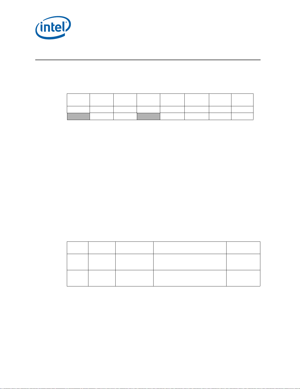
The processor stepping can be identified by the following register contents:
1
Extended
2
Model
Reserved
Reserved
31:28 27:20 19:16 15:14 13:12 11:8 7:4 3:0
Note:
1. The Extended Family , bits [27:20] are used in con junction with the F amily Code, specif ied in bits [11:8],
2. The Extended Model, bits [19:16] in conjunction with the Model Number, specified in bits [7:4], are
3. The Processor Type, specified in bits [13:12] indicates whether the processor is an original OEM
4. The Family Code corresponds to bits [11:8] of the EDX register after RESET, bits [11:8] of the EAX
5. The Model Number corresponds to bits [7:4] of the EDX register after RESET, bits [7:4] of the EAX
6. The Stepping ID in bits [3:0] indicates the revision number of that model. See Table 1 for the processor
Extended
Family
00000000b 0010b 00b 0110 1010b xxxxb
to indicate whether the processor belongs to the Intel386, Intel486, Pentium, Pentium Pro, Pentium 4,
®
or Intel
used to identify the model of the processor within the processor’s family.
processor, an OverDrive processor, or a dual processor (capable of being used in a dual processor
system).
register after the CPUID instruction is executed with a 1 in the EAX register, and the generation field of
the Device ID register accessible through Boundary Scan.
register after the CPUID instruction is executed with a 1 in the EAX register, and the model field of the
Device ID register accessible through Boundary Scan.
stepping ID number in the CPUID information.
Core™ processor family.
Processor
3
Type
Family
Code
4
Model
Number
Stepping
5
ID
6
When EAX is initialized to a value of ‘1’, the CPUID instruction returns the Extended
Family, Extended Model, Processor Type, Family C ode, Mode l Number and Step ping ID
value in the EAX register. Note that the EDX processor signature value after reset is
equivalent to the processor signature output value in the EAX register.
Cache and TLB descriptor parameters are provided in the EAX, EBX, ECX and EDX
registers after the CPUID instruction is executed with a 2 in the EAX register.
The processor can be identified by the following register contents:
Stepping Vendor ID1Host Device ID
D-2 8086h 0100h
Q-0 8086h 0100h
Notes:
1. The Vendor ID corresponds to bits 15:0 of the Vendor ID Register located at offset 00–01h in the PCI
2. The Host Device ID corresponds to bits 15:0 of the Device ID Register located at Devic e 0 offset 02–03h
3. The Processor Graphics Device ID (DID2) corresponds to bits 15:0 of the Device ID Register located at
4. The Revision Number corresponds to bits 7:0 of the Re vision ID Register located at offset 08h in the PCI
12 Specification Update
function 0 configuration space.
in the PCI function 0 configuration space.
Device 2 offset 02–03h in the PCI function 0 configuration space.
function 0 configuration space.
2
Processor Graphics
Device ID
GT1: 0102h
GT2: 0112h
GT2 (>1.3 GHz Turbo): 122h
GT1: 0102h
GT2: 0112h
GT2 (>1.3 GHz Turbo): 122h
3
Revision ID
09h
09h
4
Page 13
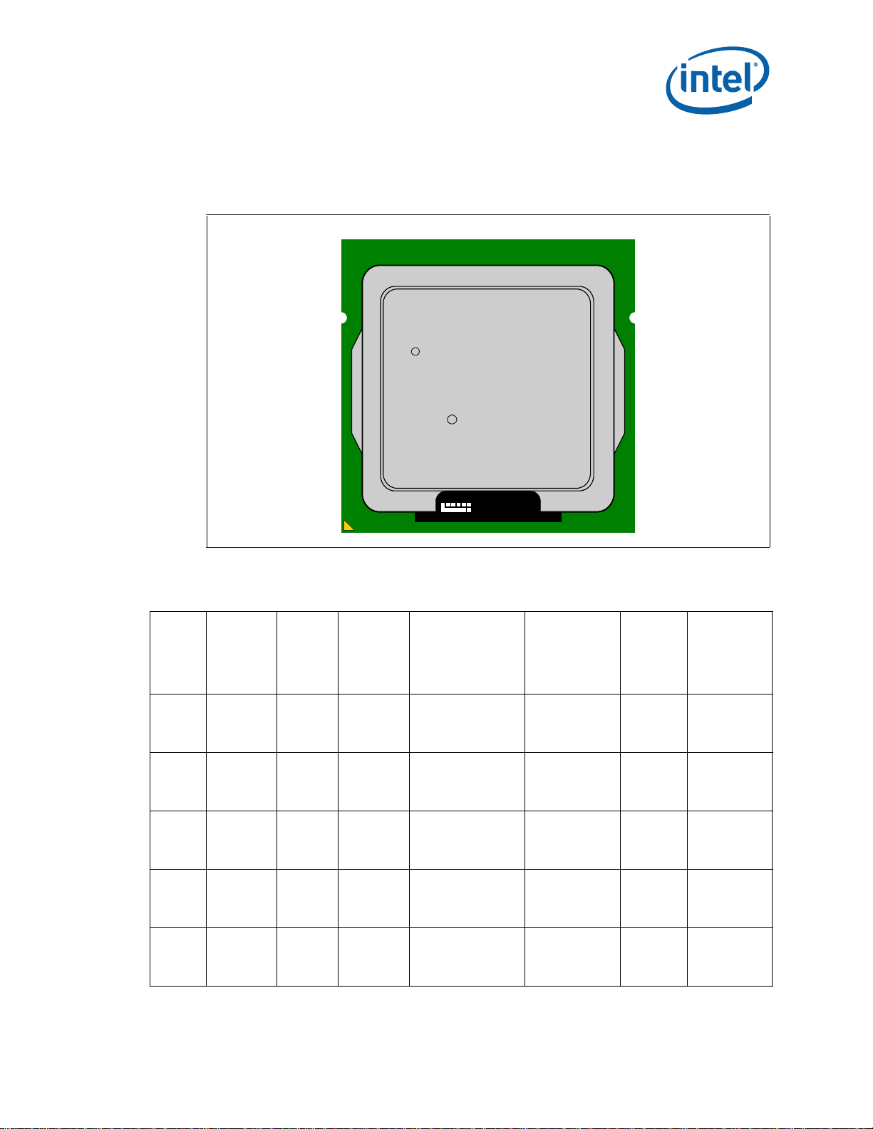
Component Marking Information
LOT NO S/N
i ©'10
BRAND PROC#
SLxxx SPEED
[COO]
[FPO]
M
e4
The processor stepping can be identified by the following component markings.
Figure 1. Processor Production Top-side Markings (Example)
Table 1. Processor Identification (Sheet 1 of 2)
Core Frequency
S-
SpecNu
mber
SR008 i5-2500K D-2 000206a7h 3.3 / 1333 / 850
SR00T i5-2500 D-2 000206a7h 3.3 / 1333 / 850
SR00Q i5-2400 D-2 000206a7h 3.1 / 1333 / 850
SR009 i5-2500S D-2 000206a7h 2.7 / 1333 / 850
SR00S i5-2400S D-2 000206a7h 2.5 / 1333 / 850
Processor
Number
Stepping
Processor
Signature
(GHz) /
DDR3 (MHz) /
Processor
Graphics
Frequency
(GHz)
®
1
Max Intel
Turbo Boost
Technology
2.0 Frequency
4 core: 3.4
3 core: 3.5
2 core: 3.6
1 core: 3.7
4 core: 3.4
3 core: 3.5
2 core: 3.6
1 core: 3.7
4 core: 3.2
3 core: 3.3
2 core: 3.3
1 core: 3.4
4 core: 2.8
3 core: 3.2
2 core: 3.6
1 core: 3.7
4 core: 2.6
3 core: 2.8
2 core: 3.2
1 core: 3.3
Shared
L3 Cache
Size (MB)
64, 6
6 3, 4, 5, 6
6 3, 4, 5, 6
6 3, 4, 5, 6
6 3, 4, 5, 6
Notes
Specification Update 13
Page 14

Table 1. Processor Identification (Sheet 2 of 2)
Core Frequency
S-
SpecNu
mber
Processor
Number
Stepping
Processor
Signature
(GHz) /
DDR3 (MHz) /
Processor
Graphics
Frequency
SR00A i5-2500T D-2 000206a7h 2.3 / 1333 / 650
SR00C i7-2600K D-2 000206a7h 3.4 / 1333 / 850
SR00B i7-2600 D-2 000206a7h 3.4 / 1333 / 850
SR00E i7-2600S D-2 000206a7h 2.8 / 1333 / 850
SR00D i5-2300 D-2 000206a7h 2.8 / 1333 / 850
Notes:
1. This column indicates maximum Intel
2. Intel
3. Intel
4. Intel
5. Intel
6. Intel
cores active respectively.
®
Hyper-Threading Technology enabled.
®
Trusted Execution Technology (Intel® TXT) enabled.
®
Virtualization Technology for IA-32, Intel® 64 and Intel® Architecture (Intel® VT-x) enabled.
®
Virtualization Technology for Directed I/O (Intel® VT-d) enabled.
®
AES-NI enabled.
®
Turbo Boost Technology 2.0 frequency (GHz) for 4,3, 2 or 1
®
Max Intel
Turbo Boost
Technology
2.0 Frequency
(GHz)
1
4 core: 2.4
3 core: 2.8
2 core: 3.2
1 core: 3.3
4 core: 3.5
3 core: 3.6
2 core: 3.7
1 core: 3.8
4 core: 3.5
3 core: 3.6
2 core: 3.7
1 core: 3.8
4 core: 2.9
3 core: 3.3
2 core: 3.7
1 core: 3.8
4 core: 2.9
3 core: 3.0
2 core: 3.0
1 core: 3.1
Shared
L3 Cache
Size (MB)
Notes
6 3, 4, 5, 6
82, 4, 6
8 2, 3, 4, 5, 6
8 2, 3, 4, 5, 6
64, 6
14 Specification Update
Page 15

Errata
BJ1. An Enabled Debug Breakpoint or Single Step Trap May Be Taken after
MOV SS/POP SS Instruction if it is Followed by an Instruction That
Signals a Floating Point Exception
Problem: A MOV SS/POP SS instruction should inhibit all interrupts including debug breakpoints
until after execution of the following instruction. This is intended to allow the sequential
execution of MOV SS/POP SS and MOV [r/e]SP, [r/e]BP instructions without having an
invalid stack during interrupt handling. However, an enabled debug breakpoint or single
step trap may be taken after MOV SS/POP SS if this instruction is followed by an
instruction that signals a floating point exception rather than a MOV [r/e]SP, [r/e]BP
instruction. This results in a debug exception being signaled on an unexpected
instruction boundary since the MOV SS/POP SS and the following instruction should be
executed atomically
Implication: This can result in incorrect signaling of a debug exception and possibly a mismatched
Stack Segment and Stack Pointer. If MOV SS/POP SS is not followed by a MOV [r/e]SP,
[r/e]BP, there may be a mismatched Stack Segment and Stack Pointer on any
exception. Intel has not observed this erratum with any commercially available
software or system.
Workaround: As recommended in the IA32 Intel® Architecture Software Developer's Manual, the use
of MOV SS/POP SS in conjunction with MOV [r/e]SP, [r/e]BP will avoid the failure since
the MOV [r/e]SP, [r/e]BP will not generate a floating point exception. Developers of
debug tools should be aware of the potential incorrect debug event signaling created by
this erratum
Status: For the steppings affected, see the Summary Tables of Changes.
BJ2. APIC Error “Received Illegal Vector” May be Lost
Problem: APIC (Advanced Programmable Interrupt Controller) may not update the ESR (Error
Status Register) flag Received Illegal V ector bit [6] properly when an illegal vector error
is received on the same internal clock that the ESR is being written (as part of the
write-read ESR access flow). The corresponding error interrupt will also not be
generated for this case.
Implication: Due to this erratum, an incoming illegal vector error may not be logged into ESR
properly and may not generate an error interrupt.
Workaround: None identified.
Status: For the steppings affected, see the Summary Tables of Changes.
BJ3. An Uncorrectable Error Logged in IA32_CR_MC2_STATUS May also
Result in a System Hang
Problem: Uncorrectable errors logged in IA32_CR_MC2_ST A TUS MSR (409H) may also result in a
system hang causing an Internal Timer Error (MCACOD = 0x0400h) to be logged in
another machine check bank (IA32_MCi_STATUS).
Implication: Uncorrectable errors logged in IA32_CR_MC2_ST A TUS can further cause a system hang
and an Internal Timer Error to be logged.
Workaround: None identified.
Status: For the steppings affected, see the Summary Tables of Changes.
Specification Update 15
Page 16

BJ4. B0-B3 Bits in DR6 For Non-Enabled Breakpoints May be Incorrectly Set
Problem: Some of the B0-B3 bits (breakpoint conditions detect flags, bits [3:0]) in DR6 may be
incorrectly set for non-enabled breakpoints when the following sequence happens:
1. MOV or POP instruction to SS (Stack Segment) selector;
2. Next instruction is FP (Floating Point) that gets FP assist
3. Another instruction after the FP instruction completes successfully
4. A breakpoint occurs due to either a data breakpoint on the preceding instruction
or a code breakpoint on the next instruction.
Due to this erratum a non-enabled breakpoint triggered on step 1 or step 2 may be
reported in B0-B3 after the breakpoint occurs in step 4.
Implication: Due to this erratum, B0-B3 bits in DR6 may be incorrectly set for non-enabled
breakpoints.
Workaround: Software should not execute a floating point instruction directly after a MOV SS or POP
SS instruction.
Status: For the steppings affected, see the Summary Tables of Changes.
BJ5. Changing the Memory Type for an In-Use Page Translation May Lead
to Memory-Ordering Violations
Problem: Under complex microarchitectural conditions, if software changes the memory type for
data being actively used and shared by multiple threads without the use of semaphores
or barriers, software may see load operations execute out of order.
Implication: Memory ordering may be violated. Intel has not observed this erratum with any
commercially available software.
Workaround: Software should ensure pages are not being actively used before requesting their
memory type be changed.
Status: For the steppings affected, see the Summary Tables of Changes.
BJ6. Code Segment Limit/Canonical Faults on RSM May be Serviced before
Higher Priority Interrupts/Exceptions and May Push the Wrong
Address Onto the Stack
Problem: Normally, when the processor encounters a Segment Limit or Canonical Fault due to
code execution, a #GP (General Protection Exception) fault is generated after all higher
priority Interrupts and exceptions are serviced. Due to this erratum, if RSM (Resume
from System Management Mode) returns to execution flow that results in a Code
Segment Limit or Canonical Fault, the #GP fault may be serviced before a higher
priority Interrupt or Exception (e.g. NMI (Non-Maskable Interrupt), Debug break(#DB),
Machine Check (#MC), etc.). If the RSM attempts to return to a non-canonical address,
the address pushed onto the stack for this #GP fault may not match the non-canonical
address that caused the fault.
Implication: Operating systems may observe a #GP fault being serviced before higher priority
Interrupts and Exceptions. Intel has not observed this erratum on any commercially
available software.
Workaround: None identified.
Status: For the steppings affected, see the Summary Tables of Changes.
16 Specification Update
Page 17

BJ7. Corruption of CS Segment Register During RSM While Transitioning
From Real Mode to Protected Mode
Problem: During the transition from real mode to protected mode, if an SMI (System
Management Interrupt) occurs between the MOV to CR0 that sets PE (Protection
Enable, bit 0) and the first far JMP, the subsequent RSM (Resume from System
Management Mode) may cause the lower two bits of CS segment register to be
corrupted.
Implication: The corruption of the bottom two bits of the CS segment register will have no impact
unless software explicitly examines the CS segment register between enabling
protected mode and the first far JMP. Intel® 64 and IA-32 Architectures Software
Developer's Manual Volume 3A: System Programming Guide, Part 1, in the section
titled “Switching to Protected Mode” recommends the far JMP immediately follows the
write to CR0 to enable protected mode. Intel has not observed this erratum with any
commercially available software.
Workaround: None identified.
Status: For the steppings affected, see the Summary Tables of Changes.
BJ8. Debug Exception Flags DR6.B0-B3 Flags May be Incorrect for Disabl ed
Breakpoints
Problem: When a debug exception is signaled on a load that crosses cache lines with data
forwarded from a store and whose corresponding breakpoint enable flags are disabled
(DR7.G0-G3 and DR7.L0-L3), the DR6.B0-B3 flags may be incorrect.
Implication: The debug exception DR6.B0-B3 flags may be incorrect for the load if the
corresponding breakpoint enable flag in DR7 is disabled.
Workaround: None identified
Status: For the steppings affected, see the Summary Tables of Changes.
BJ9. DR6.B0-B3 May Not Report All Breakpoints Matched When a MOV/POP
SS is Followed by a Store or an MMX Instruction
Problem: Normally, data breakpoints matches that occur on a MOV SS, r/m or POP SS will not
cause a debug exception immediately after MOV/POP SS but will be delayed until the
instruction boundary following the next instruction is reached. After the debug
exception occurs, DR6.B0-B3 bits will contain information about data breakpoints
matched during the MOV/POP SS as well as breakpoints detected by the following
instruction. Due to this erratum, DR6.B0-B3 bits may not contain information about
data breakpoints matched during the MOV/POP SS when the following instruction is
either an MMX instruction that uses a memory addressing mode with an index or a
store instruction.
Implication: When this erratum occurs, DR6 may not contain information about all breakpoints
matched. This erratum will not be observed under the recommended usage of the MOV
SS,r/m or POP SS instructions (i.e., following them only with an instruction that writes
(E/R)SP).
Workaround: None identified
Status: For the steppings affected, see the Summary Tables of Changes.
Specification Update 17
Page 18

BJ10. EFLAGS Discrepancy on Page Faults and on EPT-Induced VM Exits
after a Translation Change
Problem: This erratum is regarding the case where paging struct ures are modified to change a
linear address from writable to non-writable without software performing an
appropriate TLB invalidation. When a subsequent access to that address by a specific
instruction (ADD, AND, BTC, BTR, BTS, CMPXCHG, DEC, INC, NEG, NOT, OR, ROL/ROR,
SAL/SAR/SHL/SHR, SHLD, SHRD, SUB, XOR, and XADD) causes a page fault or an EPTinduced VM exit, the value saved for EFLAGS may incorrectly contain the arithmetic flag
values that the EFLAGS register would have held had the instruction completed without
fault or VM exit. For page faults, this can occur even if the fault causes a VM exit or if
its delivery causes a nested fault.
Implication: None identified. Although the EFLAGS value saved by an affected event (a page fault or
an EPT-induced VM exit) may contain incorrect arithmetic flag values, Intel has not
identified software that is affected by this erratum. This erratum will have no further
effects once the original instruction is restarted because the instruction will produce the
same results as if it had initially completed without fault or VM exit.
Workaround: If the handler of the affected events inspects the arithmetic portion of the saved
EFLAGS value, then system software should perform a synchronized paging structure
modification and TLB invalidation.
Status: For the steppings affected, see the Summary Tables of Changes.
BJ11. Fault on ENTER Instruction May Result in Unexpected Values on Stack
Frame
Problem: The ENTER instruction is used to create a procedure stack frame. Due to this erratum,
if execution of the ENTER instruction results in a fault, the dynamic storage area of the
resultant stack frame may contain unexpected values (i.e. residual stack data as a
result of processing the fault).
Implication: Data in the created stack frame may be altered following a fault on the ENTER
instruction. Please refer to “Procedure Calls For Block-Structured Languages” in IA-32
Intel® Architecture Software Developer's Manual, Vol. 1, Basic Architecture, for
information on the usage of the ENTER instructions. This erratum is not expected to
occur in ring 3. Faults are usually processed in ring 0 and stack switch occurs when
transferring to ring 0. Intel has not observed this erratum on any commercially
available software.
Workaround: None identified
Status: For the steppings affected, see the Summary Tables of Changes.
BJ12. Faulting MMX Instruction May Incorrectly Update x87 FPU Tag Word
Problem: Under a specific set of conditions, MMX stores (MOVD, MOVQ, MOVNTQ, MASKMOVQ)
which cause memory access faults (#GP, #SS, #PF, or #AC), may incorrectly update
the x87 FPU tag word register.
This erratum will occur when the following additional conditions are also met.
• The MMX store instruction must be the first MMX instruction to operate on x87 FPU
state (i.e. the x87 FP tag word is not already set to 0x0000).
• For MOVD, MOVQ, MOVNTQ stores, the instruction must use an addressing mode
that uses an index register (this condition does not apply to MASKMOVQ).
Implication: If the erratum conditions are met, the x87 FPU tag word register may be incorrectly set
to a 0x0000 value when it should not have been modified.
Workaround: None identified
18 Specification Update
Page 19

Status: For the steppings affected, see the Summary Tables of Changes.
BJ13. FREEZE_WHILE_SMM Does Not Prevent Event From Pending PEBS
During SMM
Problem: In general, a PEBS record should be generated on the first count of the event after the
counter has overflowed. However, IA32_DEBUGCTL_MSR.FREEZE_WHILE_SMM (MSR
1D9H, bit [14]) prevents performance counters from counting during SMM (System
Management Mode). Due to this erratum, if
1. A performance counter overflowed before an SMI
2. A PEBS record has not yet been generated because another count of the ev ent has
not occurred
3. The monitored event occurs during SMM
then a PEBS record will be saved after the next RSM instruction.
When FREEZE_WHILE_SMM is set, a PEBS should not be generated until the event
occurs outside of SMM.
Implication: A PEBS record may be saved after an RSM instruction due to the associated
performance counter detecting the monitored event during SMM; even when
FREEZE_WHILE_SMM is s et.
Workaround: None identified
Status: For the steppings affected, see the Summary Tables of Changes.
BJ14. General Protection Fault (#GP) for Instructions Greater than 15 Bytes
May be Preempted
Problem: When the processor encounters an instruction that is greater than 15 bytes in length, a
#GP is signaled when the instruction is decoded. Under some circumstances, the #GP
fault may be preempted by another lower priority fault (e.g. Page Fault (#PF)).
However, if the preempting lower priority faults are resolved by the operating system
and the instruction retried, a #GP fault will occur.
Implication: Software may observe a lower-priority fault occurring before or in lieu of a #GP fault.
Instructions of greater than 15 bytes in length can only occur if redundant prefixes are
placed before the instruction.
Workaround: None identified
Status: For the steppings affected, see the Summary Tables of Changes.
BJ15. #GP on Segment Selector Descriptor that Straddles Canonical
Boundary May Not Provide Correct Exception Error Code
Problem: During a #GP (General Protection Exception), the processor pushes an error code on to
the exception handler's stack. If the segment selector descriptor straddles the
canonical boundary, the error code pushed onto the stack may be incorrect.
Implication: An incorrect error code may be pushed onto the stack. Intel has not observed this
erratum with any commercially available software.
Workaround: None identified
Status: For the steppings affected, see the Summary Tables of Changes.
Specification Update 19
Page 20

BJ16. IO_SMI Indication in SMRAM State Save Area May be Set Incorrectly
Problem: The IO_SMI bit in SMRAM's location 7F A4H is set to “1” by the CPU to indicate a System
Management Interrupt (SMI) occurred as the result of executing an instruction that
reads from an I/O port. Due to this erratum, the IO_SMI bit may be incorrectly set by:
•A non-I/O instruction
•SMI is pending while a lower priority event interrupts
•A REP I/O read
•A I/O read that redirects to MWAIT
Implication: SMM handlers may get false IO_SMI indication.
Workaround: The SMM handler has to evaluate the saved context to determine if the SMI was
triggered by an instruction that read from an I/O port. The SMM handler must not
restart an I/O instruction if the platform has not been configured to generate a
synchronous SMI for the recorded I/O port address.
Status: For the steppings affected, see the Summary Tables of Changes.
BJ17. IRET under Certain Conditions May Cause an Unexpected Alignment
Check Exception
Problem: In IA-32e mode, it is possible to get an Alignment Check Exception (#AC) on the IRET
instruction even though alignment checks were disabled at the start of the IRET. This
can only occur if the IRET instruction is returning from CPL3 code to CPL3 code. IRETs
from CPL0/1/2 are not affected. This erratum can occur if the EFLAGS value on the
stack has the AC flag set, and the interrupt handler's stack is misaligned. In IA-32e
mode, RSP is aligned to a 16-byte boundary before pushing the stack frame.
Implication: In IA-32e mode, under the conditions given above, an IRET can get a #AC even if
alignment checks are disabled at the start of the IRET. This erratum can only be
observed with a software generated stack frame.
Workaround: Software should not generate misaligned stack frames for use with IRET.
Status: For the steppings affected, see the Summary Tables of Changes.
BJ18. LER MSRs May Be Unreliable
Problem: Due to certain internal processor events, updates to the LER (Last Exception Record)
MSRs, MSR_LER_FROM_LIP (1DDH) and MSR_LER_TO_LIP (1DEH), may happen when
no update was expected.
Implication: The values of the LER MSRs may be unreliable.
Workaround: None identified
Status: For the steppings affected, see the Summary Tables of Changes.
20 Specification Update
Page 21

BJ19. LBR, BTS, BTM May Report a Wrong Address when an Exception/
Interrupt Occurs in 64-bit Mode
Problem: An exception/interrupt event should be transparent to the LBR (Last Branch Record),
BTS (Branch Trace Store) and BTM (Branch Trace Message) mechanisms. However,
during a specific boundary condition where the exception/interrupt occurs right after
the execution of an instruction at the lower canonical boundary (0x00007FFFFFFFFFFF)
in 64-bit mode, the LBR return registers will save a wrong return address with bits 63
to 48 incorrectly sign extended to all 1's. Subsequent BTS and BTM operations which
report the LBR will also be incorrect.
Implication: LBR, BTS and BTM may report incorrect information in the event of an exception/
interrupt.
Workaround: None identified
Status: For the steppings affected, see the Summary Tables of Changes.
BJ20. MCi_Status Overflow Bit May Be Incorrectly Set on a Single Instance
of a DTLB Error
Problem: A single Data Translation Look Aside Buffer (DTLB) error can incorrectly set the
Overflow (bit [62]) in the MCi_Status register. A DTLB error is indicated by MCA error
code (bits [15:0]) appearing as binary value, 000x 0000 0001 0100, in the MCi_Status
register.
Implication: Due to this erratum, the Overflow bit in the MCi_Status register may not be an accurate
indication of multiple occurrences of DTLB errors. There is no other impact to normal
processor functionality.
Workaround: None identified
Status: For the steppings affected, see the Summary Tables of Changes.
BJ21. MONITOR or CLFLUSH on the Local XAPIC's Address Space Results in
Hang
Problem: If the target linear address range for a MONITO R or CLFLUSH is mapped to the local
xAPIC's address space, the processor will hang.
Implication: When this erratum occurs, the processor will hang. The local xAPIC's address space
must be uncached. The MONITOR instruction only functions correctly if the specified
linear address range is of the type write-back. CLFLUSH flushes data from the cache.
Intel has not observed this erratum with any commercially available software.
Workaround: Do not execute MONITOR or CLFLUSH instructions on the local xAPIC address space.
Status: For the steppings affected, see the Summary Tables of Changes.
Specification Update 21
Page 22

BJ22. MOV To/From Debug Registers Causes Debug Exception
Problem: When in V86 mode, if a MOV instruction is executed to/from a debug registers, a
general-protection exception (#GP) should be generated. However, in the case when
the general detect enable flag (GD) bit is set, the observed behavior is that a debug
exception (#DB) is generated instead.
Implication: With debug-register protection enabled (i.e., the GD bit set), when attempting to
execute a MOV on debug registers in V86 mode, a debug exception will be generated
instead of the expected general-protection fault.
Workaround: In general, operating systems do not set the GD bit when they are in V86 mode. The
GD bit is generally set and used by debuggers. The debug exception handler should
check that the exception did not occur in V86 mode before continuing. If the exception
did occur in V86 mode, the exception may be directed to the general-protection
exception handler.
Status: For the steppings affected, see the Summary Tables of Changes.
BJ23. PEBS Record not Updated when in Probe Mode
Problem: When a performance monitoring counter is configured for PEBS (Precise Event Based
Sampling), overflows of the counter can result in storage of a PEBS record in the PEBS
buffer. Due to this erratum, if the overflow occurs during probe mode, it may be
ignored and a new PEBS record may not be added to the PEBS buffer.
Implication: Due to this erratum, the PEBS buffer may not be updated by overflows that occur
during probe mode.
Workaround: None identified
Status: For the steppings affected, see the Summary Tables of Changes.
BJ24. Performance Monitoring Event FP_MMX_TRANS_TO_MMX May Not
Count Some Transitions
Problem: Performance Monitor Event FP_MMX_TRANS_TO_MMX (Event CCH, Umask 01H) counts
transitions from x87 Floating Point (FP) to MMX™ instructions. Due to this erratum, if
only a small number of MMX instructions (including EMMS) are executed immediately
after the last FP instruction, a FP to MMX transition may not be counted.
Implication: The count value for Performance Monitoring Event FP_MMX_TRANS_TO_MMX may be
lower than expected. The degree of undercounting is dependent on the occurrences of
the erratum condition while the counter is active. Intel has not observed this erratum
with any commercially available software.
Workaround: None identified
Status: For the steppings affected, see the Summary Tables of Changes.
BJ25. REP MOVS/STOS Executing with Fast Strings Enabled and Crossing
Page Boundaries with Inconsistent Memory Types may use an
Incorrect Data Size or Lead to Memory-Ordering Violations
Problem: Under certain conditions as described in the Software Developers Manual section “Out-
of-Order Stores For String Operations in Pentium 4, Intel Xeon, and P6 Family
Processors” the processor performs REP MOVS or REP STOS as fast strings. Due to this
erratum fast string REP MOVS/REP STOS instructions that cross page boundaries from
WB/WC memory types to UC/WP/WT memory types, may start using an incorrect data
size or may observe memory ordering violations.
Implication: Upon crossing the page boundary the following may occur, dependent on the new page
memory type:
22 Specification Update
Page 23

• UC the data size of each write will now always be 8 bytes, as opposed to the original
data size.
• WP the data size of each write will now always be 8 bytes, as opposed to the original
data size and there may be a memory ordering violation.
• WT there may be a memory ordering violation.
Workaround: Software should avoid crossing page boundaries from WB or WC memory type to UC,
WP or WT memory type within a single REP MOVS or REP STOS instruction that will
execute with fast strings enabled.
Status: For the steppings affected, see the Summary Tables of Changes.
BJ26. Reported Memory Type May Not Be Used to Access the VMCS and
Referenced Data Structures
Problem: Bits 53:50 of the IA32_VMX_BASIC MSR report the memory type that the processor
uses to access the VMCS and data structures referenced by pointers in the VMCS. Due
to this erratum, a VMX access to the VMCS or referenced data structures will instead
use the memory type that the MTRRs (memory-type range registers) specify for the
physical address of the access.
Implication: Bits 53:50 of the IA32_VMX_BASIC MSR report that the WB (write-back) memory type
will be used but the processor may use a different memory type.
Workaround: Software should ensure that the VMCS and referenced data structures are located at
physical addresses that are mapped to WB memory type by the MTRRs.
Status: For the steppings affected, see the Summary Tables of Changes.
BJ27. Single Step Interrupts with Floating Point Exception Pending May Be
Mishandled
Problem: In certain circumstances, when a floating point exception (#MF) is pending during
single-step execution, processing of the single-step debug exception (#DB) may be
mishandled.
Implication: When this erratum occurs, #DB will be incorrectly handled as follows:
•#DB is signaled before the pending higher priority #MF (Interrupt 16)
•#DB is generated twice on the same instruction
Workaround: None identified
Status: For the steppings affected, see the Summary Tables of Changes.
BJ28. Storage of PEBS Record Delayed Following Execution of MOV SS or STI
Problem: When a performance monitoring counter is configured for PEBS (Precise Event Based
Sampling), overflow of the counter results in storage of a PEBS record in the PEBS
buffer. The information in the PEBS record represents the state of the next instruction
to be executed following the counter overflow. Due to this erratum, if the counter
overflow occurs after executio n of eithe r MOV SS or STI, storage of the PEBS record is
delayed by one instruction.
Implication: When this erratum occurs, software may observe storage of the PEBS record being
delayed by one instruction following execution of MOV SS or STI. The state information
in the PEBS record will also reflect the one instruction delay.
Workaround: None identified
Status: For the steppings affected, see the Summary Tables of Changes.
Specification Update 23
Page 24

BJ29. The Processor May Report a #TS Instead of a #GP Fault
Problem: A jump to a busy TSS (Task-State Segment) may cause a #TS (invalid TSS exception)
instead of a #GP fault (general protection exception).
Implication: Operation systems that access a busy TSS may get invalid TSS fault instead of a #GP
fault. Intel has not observed this erratum with any commercially available software.
Workaround: None identified
Status: For the steppings affected, see the Summary Tables of Changes.
BJ30. VM Exits Due to “NMI-Window Exiting” May Be Delayed by One
Instruction
Problem: If VM entry is executed with the “NMI- window exiting” VM-exe cution control set to 1, a
VM exit with exit reason “NMI window” should occur before execution of any instruction
if there is no virtual-NMI blocking, no blocking of events by MOV SS, and no blocking of
events by STI. If VM entry is made with no virtual-NMI blocking but with blocking of
events by either MOV SS or STI, such a VM exit should occur after execution of one
instruction in VMX non-root operation. Due to this erratum, the VM exit may be delayed
by one additional instruction.
Implication: VMM software using “NMI-window exiting” for NMI virtualization should generally be
unaffected, as the erratum causes at most a one-instruction delay in the injection of a
virtual NMI, which is virtually asynchronous. The erratum may affect VMMs relying on
deterministic delivery of the affected VM exits.
Workaround: None identified
Status: For the steppings affected, see the Summary Tables of Changes.
BJ31. Pending x87 FPU Exceptions (#MF) May be Signaled Earlier Than
Expected
Problem: x87 instructions that trigger #MF normally service interrupts before the #MF. Due to
this erratum, if an instruction that triggers #MF is executed while Enhanced Intel
SpeedStep® Technology transitions, Intel® Turbo Boost Technology transitions, or
Thermal Monitor events occur, the pending #MF may be signaled before pending
interrupts are serviced.
Implication: Software may observe #MF being signaled before pending interrupts are serviced.
Workaround: None identified
Status: For the steppings affected, see the Summary Tables of Changes.
BJ32. Values for LBR/BTS/BTM Will be Incorrect after an Exit from SMM
Problem: After a return from SMM (System Management Mode), the CPU will incorrectly update
the LBR (Last Branch Record) and the BTS (Br anch Trace Store), hence rendering their
data invalid. The corresponding data if sent out as a BTM on the system bus will also be
incorrect. Note: This issue would only occur when one of the 3 above mentioned debug
support facilities are used.
Implication: The value of the LBR, BTS, and BTM immediately after an RSM operation should not be
used.
Workaround: None identified
Status: For the steppings affected, see the Summary Tables of Changes.
24 Specification Update
Page 25

BJ33. Unsupported PCIe Upstream Access May Complete with an Incorrect
Byte Count
Problem: PCIe Upstream IO and Configuration accesses are not supported. If an IO or
Configuration request is received upstream, the integrated PCIe controller will treat it
as an unsupported request, the request will be dropped, and a completion will be sent
with the UR (Unsupported Request) completion status. This completion, according to
the PCIe specification, should indicate a byte count of 4. Due to this erratum, the byte
count is set to the same byte count as the offending request.
Implication: The processor response to an unsupported PCIe access may not fully comply to the
PCIe specification.
Workaround: PCIe agents should not issue unsupported accesses.
Status: For the steppings affected, see the Summary Tables of Changes.
BJ34. Malformed PCIe Transactions May be Treated as Unsupported
Requests Instead of as Critical Errors
Problem: PCIe MSG/MSG_D TLPs (Transaction Layer Packets) with incorrect R outing Code as well
as the deprecated TCfgRD and TCfgWr types should be treated as malformed
transactions leading to a critical error. Due to this erratum, the integrated PCIe
controller's root ports may treat such messages as UR (Unsupported Requests).
Implication: Legacy malformed PCIe transactions may be treated as UR instead of as critical errors.
Workaround: None identified
Status: For the steppings affected, see the Summary Tables of Changes.
BJ35. PCIe Root Port May Not Initiate Link Speed Change
Problem: PCIe specification rev 2.0 requires the upstream component to maintain the PCIe link
at the target link speed or the highest speed supported by both components on the
link, whichever is lower. PCIe root port will not initiate the link speed change without
being triggered by the software. System BIOS will trigger the link speed change under
normal boot scenarios. However, BIOS is not involved in some scenarios such as link
disable/re-enable or secondary bus reset and therefore the speed change may not
occur unless initiated by the downstream component. This erratum does not affect the
ability of the downstream component to initiate a link speed change. All known 5.0Gb/
s-capable PCIe downstream components have been observed to initiate the link speed
change without relying on the root port to do so.
Implication: Due to this erratum, the PCIe root port may not initiate a link speed change during
some hardware scenarios causing the PCIe link to operate at a lower than expected
speed. Intel has not observed this erratum with any commercially available platform.
Workaround: None identified
Status: For the steppings affected, see the Summary Tables of Changes.
BJ36. Incorrect Address Computed For Last Byte of FXSAVE/FXRSTOR or
XSAVE/XRSTOR Image Leads to Partial Memory Update
Problem: A partial memory state save of the FXSAVE or XSAVE image or a partial memory state
restore of the FXRSTOR or XRSTOR image may occur if a memory address exceeds the
64KB limit while the processor is operating in 16-bit mode or if a memory address
exceeds the 4GB limit while the processor is operating in 32-bit mode.
Implication: FXSAVE/FXRSTOR or XSAVE/XRSTOR will incur a #GP fault due to the memory limit
violation as expected but the memory state may be only partially saved or restored.
Specification Update 25
Page 26

Workaround: Software should avoid memory accesses that wrap around the respective 16-bit and
32-bit mode memory limits.
Status: For the steppings affected, see the Summary Tables of Changes.
BJ37. Performance Monitor SSE Retired Instructions May Return Incorrect
Values
Problem: Performance Monitoring counter SIMD_INST_RETIRED (Event: C7H) is used to track
retired SSE instructions. Due to this erratum, the processor may also count other types
of instructions resulting in higher than expected values.
Implication: Performance Monitoring counter SIMD_INST_RETIRED may report count higher than
expected.
Workaround: None identified
Status: For the steppings affected, see the Summary Tables of Changes.
BJ38. FP Data Operand Pointer May Be Incorrectly Calculated After an FP
Access Which Wraps a 4-Gbyte Boundary in Code That Uses 32-Bit
Address Size in 64-bit Mode
Problem: The FP (Floating Point) Data Operand Pointer is the effective address of the operand
associated with the last non-control FP instruction executed by the processor. If an 80bit FP access (load or store) uses a 32-bit address size in 64-bit mode and the memory
access wraps a 4-Gbyte boundary and the FP environment is subsequently saved, the
value contained in the FP Data Operand Pointer may be incorrect.
Implication: Due to this erratum, the FP Data Operand Pointer may be incorrect. Wrapping an 80-bit
FP load around a 4-Gbyte boundary in this way is not a normal programming practice.
Intel has not observed this erratum with any commercially available software.
Workaround: If the FP Data Operand Pointer is used in a 64-bit oper ating system which may run code
accessing 32-bit addresses, care must be taken to ensure that no 80-bit FP accesses
are wrapped around a 4-Gbyte boundary.
Status: For the steppings affected, see the Summary Tables of Changes.
26 Specification Update
Page 27

BJ39. FP Data Operand Pointer May Be Incorrectly Calculated After an FP
Access Which Wraps a 64-Kbyte Boundary in 16-Bit Code
Problem: The FP (Floating Point) Data Operand Pointer is the effective address of the operand
associated with the last non-control FP instruction executed by the processor. If an 80-
bit FP access (load or store) occurs in a 16-bit mode other than protected mode (in
which case the access will produce a segment limit violation), the memory access
wraps a 64-Kbyte boundary, and the FP environment is subsequently saved, the value
contained in the FP Data Operand Pointer may be incorrect.
Implication: Due to this erratum, the FP Data Operand Pointer may be incorrect. Wrapping an 80-bit
FP load around a segment boundary in this way is not a normal programming practice.
Intel has not observed this erratum with any commercially available software.
Workaround: If the FP Data Operand Pointer is used in an operating system which may run 16-bit FP
code, care must be taken to ensure that no 80-bit FP accesses are wrapped around a
64-Kbyte boundary.
Status: For the steppings affected, see the Summary Tables of Changes.
BJ40. Spurious Interrupts May be Generated From the Intel® VT-d Remap
Engine
Problem: If software clears the F (Fault) bit 127 of the Fault Recording Register (FRCD_REG at
offset 0x208 in Remap Engine BAR) by writing 1b through RW1C command (Read Write
1 to Clear) when the F bit is already clear then a spurious interrupt from Intel VT-d
(Virtualization Technology for Directed I/O) Remap Engine may be observed.
Implication: Due to this erratum, spurious interrupts will occur from the Intel VT-d Remap Engine
following RW1C clearing F bit.
Workaround: None identified
Status: For the steppings affected, see the Summary Tables of Changes.
BJ41. Fault Not Reported When Setting Reserved Bits of Intel® VT-d Queued
Invalidation Descriptors
Problem: Reserved bits in the Queued Invalidation descriptors of Intel VT-d (Virtualization
Technology for Directed I/O) are expected to be zero, meaning that software must
program them as zero while the processor checks if they are not zero. Upon detection
of a non-zero bit in a reserved field an Intel VT-d fault should be recorded. Due to this
erratum the processor does not check reserved bit values for Queued Invalidation
descriptors.
Implication: Due to this erratum, faults will not be reported when writing to reserved bits of Intel
VT-d Queued Invalidation Descriptors.
Workaround: None identified
Status: For the steppings affected, see the Summary Tables of Changes.
Specification Update 27
Page 28

BJ42. VPHMINPOSUW Instruction in Vex Format Does Not Signal #UD When
vex.vvvv !=1111b
Problem: Processor does not signal #UD fault when executing the reserved instruction
VPHMINPOSUW with vex.vvvv !=1111b.
Implication: Executing VPHMINPOSUW with vex.vvvv !=1111b results in the same behavior as
executing with vex.vvvv=1111b.
Workaround: Software should not use VPHMINPOSUW with vex.vvvv !=1111b in order to ensure
future compatibility.
Status: For the steppings affected, see the Summary Tables of Changes.
BJ43. LBR, BTM or BTS Records May have Incorrect Branch From
Information After an EIST/T-state/S-state/C1E Transition or Adaptive
Thermal Throttling
Problem: The “From” address associated with the LBR (Last Branch Record), BTM (Branch Trace
Message) or BTS (Branch Trace Store) may be incorrect for the first branch after a
transition of:
• EIST (Enhanced Intel® SpeedStep Technology)
• T-state (Thermal Monitor states)
• S1-state (ACPI package sleep state)
• C1E (Enhanced C1 Low Power state)
• Adaptive Thermal Throttling
Implication: When the LBRs, BTM or BTS are enabled, some records may have incorrect branch
“From” addresses for the first branch after a transition of EIST, T-states, S-states, C1E,
or Adaptive Thermal Throttling.
Workaround: None identified
Status: For the steppings affected, see the Summary Tables of Changes.
BJ44. VMREAD/VMWRITE Instruction May Not Fail When Accessing an
Unsupported Field in VMCS
Problem: The Intel® 64 and IA -32 Arch itectures Softw are Developer's Manual, Volume 2B states
that execution of VMREAD or VMWRITE should fail if the value of the instruction's
register source operand corresponds to an unsupported field in the VMCS (Virtual
Machine Control Structure). The correct operation is that the logical processor will set
the ZF (Zero Flag), write 0CH into the VM-instruction error field and for VMREAD leave
the instruction's destination operand unmodified. Due to this erratum, the instruction
may instead clear the ZF, leave the VM-instruction error field unmodified and for
VMREAD modify the contents of its destination operand.
Implication: Accessing an unsupported field in VMCS will fail to properly report an error. In addition,
VMREAD from an unsupported VMCS field may unexpectedly change its destination
operand. Intel has not observed this erratum with any commercially a v ailable software.
Workaround: Software should avoid accessing unsupported fields in a VMCS
Status: For the steppings affected, see the Summary Tables of Changes.
28 Specification Update
Page 29

BJ45. Clock Modulation Duty Cycle Cannot be Programmed to 6.25%
Problem: When prog ramming field T_ ST A TE_REQ of the IA32 _CLOCK_MODULA T ION MSR (19AH)
bits [3:0] to '0001, the actual clock modulation duty cycle will be 12.5% instead of the
expected 6.25% ratio.
Implication: Due to this erratum, it is not possible to program the clock modulation to a 6.25% duty
cycle.
Workaround: None identified
Status: For the steppings affected, see the Summary Tables of Changes.
BJ46. Execution of VAESIMC or VAESKEYGENASSIST With An Illegal Value
for VEX.vvvv May Produce a #NM Exception
Problem: The VAESIMC and VAESKEYGENASSIST instructions should produce a #UD (Invalid-
Opcode) exception if the value of the vvvv field in the VEX prefix is not 1111b. Due to
this erratum, if CR0.TS is “1”, the processor may instead produce a #NM (Device-Not-
Available) exception.
Implication: Due to this erratum, some undefined instruction encodings may produce a #NM instead
of a #UD exception.
Workaround: Software should always set the vvvv field of the VEX prefix to 1111b for instances of
the VAESIMC and VAESKEYGENASSIST instructions
Status: For the steppings affected, see the Summary Tables of Changes.
BJ47. Memory Aliasing of Code Pages May Cause Unpredictable System
Behavior
Problem: The type of memory aliasing contributing to this erratum is the case where two
different logical processors have the same code page mapped with two different
memory types. Specifically, if one code page is mapped by one logical processor as
write-back and by another as uncachable and certain instruction fetch timing conditions
occur, the system may experience unpredictable behavior.
Implication: If this erratum occurs the system may have unpredictable behavior including a system
hang. The aliasing of memory regions, a condition necessary for this erratum to occur,
is documented as being unsupported in the Intel 64 and IA-32 Intel® Architecture
Software Developer's Manual, Volume 3A, in the section titled Programming the PAT.
Intel has not observed this erratum with any commercially available software or
system.
Workaround: Code pages should not be mapped with uncacheable and cacheable memory types at
the same time.
Status: For the steppings affected, see the Summary Tables of Changes.
Specification Update 29
Page 30

BJ48. PCI Express Graphics Receiver Error Reported When Receiver With
L0s Enabled and Link Retrain Performed
Problem: If the Processor PCI Express root port is the receiver with L0s enabled and the root port
itself initiates a transition to the recovery state via the retrain link configuration bit in
the 'Link Control' register (Bus 0; Device 1; Functions 0, 1, 2 and Device 6; Function 0;
Offset B0H; bit 5), then the root port may not mask the receiver or bad DLLP (Data
Link Layer Packet) errors as expected. These correctable errors should only be
considered valid during PCIe configuration and L0 but not L0s. This causes the
processor to falsely report correctable errors in the 'Device Status' register (Bus 0;
Device 1; Functions 0, 1, 2 and Device 6; Function 0; Offset AAH; bit 0) upon receiving
the first FTS (Fast Training Sequence) when exiting Receiver L0s. Under normal
conditions there is no reason for the Root Port to initiate a transition to Recov ery. Note:
This issue is only exposed when a recovery event is initiated by the processor.
Implication: The processor does not comply with the PCI Express 2.0 Specification. This does not
impact functional compatibility or interoperability with other PCIe devices.
Workaround: None identified.
Status: For the steppings affected, see the Summary Tables of Changes.
BJ49. Unexpected #UD on VZEROALL/VZEROUPPER
Problem: Execution of the VZEROALL or VZEROUPPER in structions in 64-bit mode with VEX.W set
to 1 may erroneously cause a #UD (invalid-opcode exception).
Implication: The affected instructions may produce unexpected invalid-opcode exceptions in 64-bit
mode.
Workaround: Compilers should encode VEX.W = 0 for executions of the VZEROALL and VZEROUPPER
instructions in 64-bit mode to ensure future compatibility.
Status: For the steppings affected, see the Summary Tables of Changes.
BJ50. Perfmon Event LD_BLOCKS.STORE_FORWARD May Overcount
Problem: Perfmon LD_BLOCKS.STORE_FORWARD (event 3H, umask 01H) may overcount in the
cases of 4KB address aliasing and in some cases of blocked 32-byte AVX load
operations. 4KB address aliasing happens when unrelated load and store that have
different physical addresses appear to overlap due to partial address check done on the
lower 12 bits of the address. In some cases such memory aliasing can cause load
execution to be significantly delayed. Blocked AVX load oper ations refer to 32-byte A VX
loads that are blocked due to address conflict with an older store.
Implication: The perfmon event LD_BLOCKS.STORE_FORWARD may overcount for these cases.
Workaround: None identified.
Status: For the steppings affected, see the Summary Tables of Changes.
30 Specification Update
Page 31

BJ51. Conflict Between Processor Graphics Internal Message Cycles And
Graphics Reads From Certain Physical Memory Ranges May Cause a
System Hang
Problem: Processor Graphics internal message cycles occurring concurrently with a physical
memory read by graphics from certain memory ranges may cause memory reads to be
stalled resulting in a system hang. The following physical page (4K) addresses cannot
be assigned to Processor Graphics: 00_2005_0xxx, 00_2013_0xxx, 00_2013_8xxx and
00_4000_4xxx.
Implication: Due to this erratum, accesses by the graphics engine to the defined memory ranges
may cause memory reads to be stalled, resulting in a system hang.
Workaround:
Workaround: A BIOS code change has been identified and may be implemented as a workaround for
this erratum.
Status: For the steppings affected, see the Summary Tables of Changes.
BJ52. Execution of Opcode 9BH with the VEX Opcode Extension May Produce
a #NM Exception
Problem: Attempt to use opcode 9BH with a VEX opcode extension should produce a #UD
(Invalid-Opcode) ex ception. Du e to this erratum, if CR0.MP and CR0.T S are both 1, the
processor may produce a #NM (Device-Not-Available) exception if one of the following
conditions exists:
•66H, F2H, F3H or REX as a preceding prefix;
•An illegal map specified in the VEX.mmmmm field;
Implication: Due to this erratum, some undefined instruction encodings may produce a #NM instead
of a #UD exception.
Workaround: Software should not use opcode 9BH with the VEX opcode extension.
Status: For the steppings affected, see the Summary Tables of Changes.
BJ53. Executing The GETSEC Instruction While Throttling May Result in a
Processor Hang
Problem: If the processor throttles due to either high temperature thermal conditions or due to
an explicit operating system throttling request (TT1) while ex ecuting GETSEC[SENTER]
or GETSEC[SEXIT] instructions, then under certain circumstances, the processor may
hang. Intel has not been observed this erratum with any commercially available
software.
Implication: Possible hang during execution of GETSEC instruction.
Workaround: None identified.
Status: For the steppings affected, see the Summary Tables of Changes.
Specification Update 31
Page 32

BJ54. A Write to the IA32_FIXED_CTR1 MSR May Result in Incorrect Value in
Certain Conditions
Problem: Under specific internal conditions, if software tries to write the IA32_FIXED_CTR1 MSR
(30AH) a value that has all bits [31:1] set while the counter was just about to overflow
when the write is attempted (i.e. its value was 0xFFFF FFFF FFFF), then due to this
erratum the new value in the MSR may be corrupted.
Implication: Due to this erratum, IA32_FIXED_CTR1 MSR may be written with a corrupted value.
Workaround: Software may avoid this erratum by writing zeros to the IA32_FIXED_CTR1 MSR,
before the desired write operation.
Status: For the steppings affected, see the Summary Tables of Changes.
BJ55. Instruction Fetch May Cause Machine Check if Page Size and Memory
Type Was Changed Without Invalidation
Problem: This erratum may cause a machine-check error (IA32_MCi_STATUS.MCACOD=0150H)
on the fetch of an instruction that crosses a 4-KByte address boundary. It applies only
if (1) the 4-KByte linear region on which the instruction begins is originally translated
using a 4-KByte page with the WB memory type; (2) the paging structures are later
modified so that linear region is translated using a large page (2-MByte, 4-MByte, or 1GByte) with the UC memory type; and (3) the instruction fetch occurs after the pagingstructure modification but before software invalidates any TLB entries for the linear
region.
Implication: Due to this erratum an unexpected machine check with error code 0150H may occur,
possibly resulting in a shutdown. Intel has not observed this erratum with any
commercially available software.
Workaround: Software should not write to a paging-structure entry in a way that would change, for
any linear address, both the page size and the memory type. It can instead use the
following algorithm: first clear the P flag in the relevant paging-structure entry (e.g.,
PDE); then invalidate any translations for the affected linear addresses; and then
modify the relevant paging-structure entry to set the P flag and establish the new page
size and memory type.
Status: For the steppings affected, see the Summary Tables of Changes.
BJ56. Reception of Certain Malformed Transactions May Cause PCIe Port to
Hang Rather Than Reporting an Error
Problem: If the processor receives an upstream malformed non posted packet for w hich the type
field is IO, Configuration or the deprecated TCfgRd and the format is 4 DW header, then
due to this erratum the integrated PCIe controller may hang instead of reporting the
malformed packet error or issuing an unsupported request completion transaction.
Implication: Due to this erratum, the processor may hang without reporting errors when receiving a
malformed PCIe transaction. Intel has not observed this erratum with any commercially
available device.
Workaround: None identified. Upstream transaction initiators should avoid issuing unsupported
requests with 4 DW header formats.
Status: For the steppings affected, see the Summary Tables of Changes.
32 Specification Update
Page 33

BJ57. PCIe LTR Incorrectly Reported as Being Supported
Problem: LTR (Latency Tolerance Reporting) is a new optional feature specified in PCIe rev. 2.1.
The processor reports L TR as supported in LTRS bit in DCAP2 register (bus 0; Device 1;
Function 0; offset 0xc4), but this feature is not supported.
Implication: Due to this erratum, LTR is always reported as supported by the LTRS bit in the DCAP2
register.
Workaround: None identified.
Status: For the steppings affected, see the Summary Tables of Changes.
BJ58. PerfMon Overflow Status Can Not be Cleared After Certain Conditions
Have Occurred
Problem: Under very specific timing conditions, if software tries to disable a PerfMon counter
through MSR IA32_PERF_GLOBAL_CTRL (0x38F) or through the per-counter event-
select (e.g. MSR 0x186) and the counter reached its overflow state very close to that
time, then due to this erratum the overflow status indication in MSR
IA32_PERF_GLOBAL_STAT (0x38E) may be left set with no way for software to clear it.
Implication: Due to this erratum, software may be unable to clear the PerfMon counter overflow
status indication.
Workaround: Software may avoid this erratum by clearing the PerfMon counter value prior to
disabling it and then clearing the overflow status indication bit.
Status: For the steppings affected, see the Summary Tables of Changes.
BJ59. XSAVE Executed During Paging-Structure Modification May Cause
Unexpected Processor Behavior
Problem: Execution of XSAVE may result in unexpected behavior if the XSAVE instruction writes
to a page while another logical processor clears the dirty flag or the accessed flag in
any paging-structure entry that maps that page.
Implication: This erratum may cause unpredictable system behavior. Intel has not observed this
erratum with any commercially available software.
Workaround: It is possible for the BIOS to contain a workaround for this erratum.
Status: For the steppings affected, see the Summary Tables of Changes.
BJ60. C-state Exit Latencies May be Higher Than Expected
Problem: Core C -state exit can be delayed if a P-state transition is requested before the pending
C-state exit request is completed. Under certain internal conditions the core C-state
exit latencies may be over twice the value specified in the Intel® 64 and IA-32
Architectures Optimization Reference Manual.
Implication: While typical exit latencies are not impacted, the worst case core C-state exit latency
may be over twice the value specified in the Intel® 64 and IA-32 Architectures
Optimization Reference Manual and may lead to a delay in servicing interrupts. Intel
has not observed any system failures due to this erratum.
Workaround: It is possible for the BIOS to contain a workaround for this erratum.
Status: For the steppings affected, see the Summary Tables of Changes.
Specification Update 33
Page 34

BJ61. MSR_Temperature_Target May Have an Incorrect Value in the
Temperature Control Offset Field
Problem: Under certain conditions the value in MSR_Temperature_Target (1A2H) bits [15:8]
(Temperature Control Offset) may indicate a temperature up to 25 degrees higher than
intended.
Implication: Due to this erratum, fan speed control algorithms that rely on this value may not
function as expected
Workaround: It is possible for the BIOS to contain a workaround for this erratum.
Status: For the steppings affected, see the Summary Tables of Changes.
BJ62. Intel® VT-d Interrupt Remapping Will Not Report a Fault if Interrupt
Index Exceeds FFFFH
Problem: With Intel® VT-d (Virtualization Technology for Directed I/O) interrupt remapping, if
subhandle valid (bit 3) is set in the address of an interrupt request, the interrupt index
is computed as the sum of the interrupt request’s handle and subhandle. If the sum is
greater than FFFFH (the maximum possible interrupt-remapping table size) a
remapping fault with fault reason 21H should be reported. Due to this erratum, this
condition is not reported as a fault; instead, the low 16 bits of the sum are erroneously
used as an interrupt index to access the interrupt-remapping table.
Implication: If the interrupt index of an interrupt request exceeds FFFFH, a remapping fault with
fault reason 21H is not reported and instead the request uses the IRTE (interruptremapping table entry) indexed by the low 16 bits of the interrupt index.
Workaround: Software can use requestor-id verification to block the interrupts that would be
delivered due to this erratum. Interrupts blocked in this way produce a remapping fault
with fault reason 26H.
Status: For the steppings affected, see the Summary Tables of Changes.
BJ63. PCIe Link Speed May Not Change From 5.0 GT/s to 2.5 GT/s
Problem: If a PCI Express device changes its supported PCIe link speed from 5.0 GT/s to 2.5 GT/
s without initiating a speed change request and subsequently the L1 power
management mode is entered, further retrains initiated by software will not change
speed to 2.5 GT/s.
Implication: Intel has not observed any PCI Express device that changes supported link speed
without actually initiating a speed change.
Workaround: None identified.
Status: For the steppings affected, see the Summary Tables of Changes.
BJ64. L1 Data Cache Errors May be Logged With Level Set to 1 Instead of 0
Problem: When an L1 Data Cache error is logged in IA32_MCi_STATUS[15:0], which is the MCA
Error Code Field, with a cache error type of the format 0000 0001 RRRR TTLL, the LL
field may be incorrectly encoded as 01 instead of 00.
Implication: An error in the L1 Data Cache may report the same LL value as the L2 Cache. Software
should not assume that an LL value of 01 is the L2 Cache.
Workaround: None identified.
Status: For the steppings affected, see the Summary Tables of Changes.
34 Specification Update
Page 35

BJ65. An Unexpected Page Fault or EPT Violation May Occur After Another
Logical Processor Creates a Valid Translation for a Page
Problem: An unexpected page fault (#PF) or EPT violation may occur for a page under the
following conditions:
•The paging structures initially specify no valid translation for the page.
•Software on one logical processor modifies the paging structures so that there is a
valid translation for the page (e.g., by setting to 1 the present bit in one of the pagingstructure entries used to translate the page).
•Software on another logical processor observes this modification (e.g., by accessing a
linear address on the page or by reading the modified paging-structure entry and
seeing value 1 for the present bit).
•Shortly thereafter, software on that other logical processor performs a store to a linear
address on the page.
In this case, the store may cause a page fault or EPT violation that indicates that there
is no translation for the page (e.g., with bit 0 clear in the page-fault error code,
indicating that the fault was caused by a not-present page). Intel has not observed this
erratum with any commercially available software.
Implication: An unexpected page fault may be reported. There are no other side effects due to this
erratum.
Workaround: System software can be constructed to tolerate these unexpected page faults. See
Section “Propagation of Paging-Structure Changes to Multiple Processors” of V o lume 3B
of IA-32 Intel® Architecture Software Developer’s Manual, for recommendations for
software treatment of asynchronous paging-structure updates.
Status: For the steppings affected, see the Summary Tables of Changes.
BJ66. TSC Deadline Not Armed While in APIC Legacy Mode
Problem: Under specific timing conditions, when in Legacy APIC Mode, writing to
IA32_TSC_DEADLINE MSR (6E0H) may fail to arm the TSC Deadline (Time Stamp
Counter Deadline) event as expected. Exposure to this erratum is dependent on the
proximity of TSC_Deadline MSR Write to a Timer CCR register read or to a write to the
Timer LVT that enabled the TSC Deadline mode (writing 10 to bits [18:17] of Timer
LVT).
Implication: Due to this erratum the expected timer event will either not be generated or will be
generated at a wrong time. The TSC Deadline may fail until an LVT write to transition
from “TSC Deadline mode” back to “Timer mode” occurs or until the next reset.
Workaround: It is possible for the BIOS to contain a workaround for this erratum.
Status: For the steppings affected, see the Summary Tables of Changes.
BJ67. PCIe Upstream TCfgWr May Cause Unpredictable System Behavior
Problem: T CfgW r (Trusted Configuration Writes) is a PCIe Base spec deprecated transaction type
which should be treated as a malformed packet. If a PCIe upstream TCfgWr request is
received, then due to this erratum the request may not be managed as a Malformed
Packet.
Implication: Upstream memory writes subsequent to a TCfgWr transaction may cause unpredictable
system behavior. Intel has not observed any PCIe Device that sends such a TCfgWr
request.
Workaround: PCIe end points should not initiate upstream TCfgWr requests.
Status: For the steppings affected, see the Summary Tables of Changes.
Specification Update 35
Page 36

BJ68. Processor May Fail to Acknowledge a TLP Request
Problem: When a PCIe root port’s receiver is in Receiv er L0s power state and the port initiates a
Recovery event, it will issue Training Sets to the link partner. The link partner will
respond by initiating an L0s exit sequence. Prior to transmitting its own Training Sets,
the link partner may transmit a TLP (Transaction Layer Packet). Due to this erratum,
the root port may not acknowledge the TLP request.
Implication: After completing the Recovery event, the PCIe link partner will replay the TLP request.
The link partner may set a Correctable Error status bit, which has no functional effect.
Workaround: None identified.
Status: For the steppings affected, see the Summary Tables of Changes.
BJ69. Executing The GETSEC Instruction While Throttling May Result in a
Processor Hang
Problem: If the processor throttles due to either high temperature thermal conditions or due to
an explicit operating system throttling request (TT1) while executing GETSEC[SENTER]
or GETSEC[SEXIT] instructions, then under certain circumstances, the processor may
hang.
Implication: Possible hang during execution of GETSEC instruction. Intel has not been observed this
erratum with any commercially available software.
Workaround: None Identified.
Status: For the steppings affected, see the Summary Tables of Changes.
BJ70. PerfMon Event LOAD_HIT_PRE.SW_PREFETCH May Overcount
Problem: PerfMon event LOAD_HIT_PRE.SW_PREFETCH (event 4CH, umask 01H) should count
load instructions hitting an ongoing software cache fill request initiated by a preceding
software prefetch instruction. Due to this erratum, this event may also count when
there is a preceding ongoing cache fill request initiated by a locking instruction.
Implication: PerfMon event LOAD_HIT_PRE.SW_PREFETCH may overcount.
Workaround: None identified.
Status: For the steppings affected, see the Summary Tables of Changes.
BJ71. Execution of FXSAVE or FXRSTOR With the VEX Prefix May Produce a
#NM Exception
Problem: Attempt to use FXSAVE or FXRSTOR with a VEX prefix should produce a #UD (Invalid-
Opcode) exception. If either the TS or EM flag bits in CR0 are set, a #NM (device-notavailable) exception will be raised instead of #UD exception.
Implication: Due to this erratum a #NM exception may be signaled instead of a #UD exception on
an FXSAVE or an FXRSTOR with a VEX prefix.
Workaround: Software should not use FXSAVE or FXRSTOR with the VEX prefix.
Status: For the steppings affected, see the Summary Tables of Changes.
36 Specification Update
Page 37

BJ72. Unexpected #UD on VPEXTRD/VPINSRD
Problem: Execution of the VPEXTRD or VPINSRD instructions outside of 64-bit mode with VEX.W
set to 1 may erroneously cause a #UD (invalid-opcode exception).
Implication: The aff e c ted instructions may produce unexpected invalid-opcode exceptions outside
64-bit mode.
Workaround: Software should encode VEX.W = 0 for executions of the VPEXTRD and VPINSRD
instructions outside 64-bit mode.
Status: For the steppings affected, see the Summary Tables of Changes.
BJ73. Restrictions on ECC_Inject_Count Update When Disabling and
Enabling Error Injection
Problem: The artificial injection of memory ECC errors allows control of the number of injections
through the ECC_Inject_Count (MMIO) register. When using this counter option, if the
transaction count is decreased after the injections were previously enabled the errors
may not be injected properly.
Implication: Due to this erratum, injected errors may not be logged as expected.
Workaround: Do not decrease the error counter value if it was previously enabled. Reset should be
applied before decreasing the error count value.
Status: For the steppings affected, see the Summary Tables of Changes.
BJ74. Successive Fixed Counter Overflows Ma y be Discarded
Problem: Under specific internal conditions, when using Freeze P erfMon on PMI feature (bit 12 in
IA32_DEBUGCTL.Freeze_PerfMon_on_PMI, MSR 1D9H), if two or more PerfMon Fixed
Counters overflow very closely to each other, the overflow may be mishandled for some
of them. This means that the counter’s overflow status bit (in
MSR_PERF_GLOBAL_STATUS, MSR 38EH) may not be updated properly; additionally,
PMI interrupt may be missed if software programs a counter in Sampling-Mode (PMI bit
is set on counter configuration).
Implication: Successive Fixed Counter overflows may be discarded when Freeze PerfMon on PMI is
used.
Workaround: Software can avoid this by:
•Avoid using Freeze PerfMon on PMI bit
•Enable only one fixed counter at a time when using Freeze PerfMon on PMI
Status: For the steppings affected, see the Summary Tables of Changes.
BJ75. #GP May be Signaled When Invalid VEX Prefix Precedes Conditional
Branch Instructions
Problem: When a 2-byte opcode of a conditional branch (opcodes 0F8xH, for any value of x)
instruction resides in 16-bit code-segment and is associated with invalid VEX prefix, it
may sometimes signal a #GP fault (illegal instruction length > 15-bytes) instead of a
#UD (illegal opcode) fault.
Implication: Due to this erratum, #GP fault instead of a #UD may be signaled on an illegal
instruction.
Workaround: None identified.
Status: For the steppings affected, see the Summary Tables of Changes.
Specification Update 37
Page 38

BJ76. A Read from The APIC-Timer CCR May Disarm The TSC_Deadline
Counter
Problem: When in TSC Deadline mode with TSC_Deadline timer armed
(IA32_TSC_DEADLINE<>0, MSR 6E0H), a read from the local APIC’s CCR (current
count register) using RDMSR 0839H may disarm the TSC Deadline timer without
generating an interrupt as specified in the APIC Timer LVT (Local Vector Table) entry.
Implication: Due to this erratum, unexpected disarming of the TSC_Deadline counter and possible
loss of an interrupt may occur.
Workaround: It is possible for the BIOS to contain a workaround for this erratum.
Status: For the steppings affected, see the Summary Tables of Changes.
BJ77. An Unexpected PMI May Occur After Writing a Large Value to
IA32_FIXED_CTR2
Problem: If the fixed-function performance counter IA32_FIXED_CTR2 MSR (30BH) is configured
to generate a performance-monitor interrupt (PMI) on overflow and the counter’s v alue
is greater than FFFFFFFFFFC0H, then this erratum may incorrectly cause a PMI if
software performs a write to this counter.
Implication: A PMI may be generated unexpectedly when programming IA32_FIXED_CTR2. Other
than the PMI, the counter programming is not affected by this erratum as the
attempted write operation does succeed.
Workaround: None identified.
Status: For the steppings affected, see the Summary Tables of Changes.
38 Specification Update
Page 39

Specification Changes
The Specification Changes listed in this section apply to the following documents:
®
•Intel
•Intel® 64 and IA-32 Architectures Software Developer’s Manual, Volume 2A:
•Intel® 64 and IA-32 Architectures Software Developer’s Manual, Volume 2B:
•Intel® 64 and IA-32 Architectures Software Developer’s Manual, Volume 3A:
•Intel® 64 and IA-32 Architectures Software Developer’s Manual, Volume 3B:
There are no new Specification Changes in this Specification Update revision.
64 and IA-32 Architectures Software Developer’s Manual, Volume 1: Basic
Architecture
Instruction Set Reference Manual A-M
Instruction Set Reference Manual N-Z
System Programming Guide
System Programming Guide
Specification Update 39
Page 40

Specification Clarifications
The Specification Clarifications listed in this section may apply to the following
documents:
•Intel® 64 and IA-32 Architectures Software Developer’s Manual, Volume 1: Basic
Architecture
•Intel® 64 and IA-32 Architectures Software Developer’s Manual, Volume 2A:
Instruction Set Reference Manual A-M
•Intel® 64 and IA-32 Architectures Software Developer’s Manual, Volume 2B:
Instruction Set Reference Manual N-Z
•Intel® 64 and IA-32 Architectures Software Developer’s Manual, Volume 3A:
System Programming Guide
•Intel® 64 and IA-32 Architectures Software Developer’s Manual, Volume 3B:
System Programming Guide
There are no new Specification Changes in this Specification Update revision.
40 Specification Update
Page 41

Documentation Changes
The Documentation Changes listed in this section apply to the following documents:
®
•Intel
•Intel® 64 and IA-32 Architectures Software Developer’s Manual, Volume 2A:
•Intel® 64 and IA-32 Architectures Software Developer’s Manual, Volume 2B:
•Intel® 64 and IA-32 Architectures Software Developer’s Manual, Volume 3A:
•Intel® 64 and IA-32 Architectures Software Developer’s Manual, Volume 3B:
All Documentation Changes will be incorporated into a future version of the appropriate
Processor documentation.
Note: Documentation changes for Intel
Developer's Manual volumes 1, 2A, 2B, 3A, and 3B will be posted in a separate
document, Intel® 64 and IA-32 Architecture Software Developer's Manual
Documentation Changes. Follow the link below to become familiar with this file.
http://developer.intel.com/products/processor/manuals/index.htm
64 and IA-32 Architectures Software Developer’s Manual, Volume 1: Basic
Architecture
Instruction Set Reference Manual A-M
Instruction Set Reference Manual N-Z
System Programming Guide
System Programming Guide
®
64 and IA-32 Architecture Software
§ §
Specification Update 41
 Loading...