

Page 1

Intel® Security Technologies
BpmGen2 GUI User Guide
Revision 0.5
Last updated March 5, 2020
Important Changes and Updates:
Jan 18, 2017 Initial draft
Feb 22, 2017 Updated for tool changes
Dec 19, 2017 Updated for numerous architecture changes
Mar 5, 2020 Updated for numerous architecture changes
Note: BpmGen2 GUI is significantly different from and not backward compatible with the
original BpmGen GUI tool. This tool is provided “as is” with no express or implied warranty
and thus it is the user’s responsibility to verify proper functionality.
1 Introduction
1.1 Overview
Intel© has converged Intel Trusted Execution Technology (Intel TXT) with Intel Boot Guard Technology (Intel BtG)
merging redundant structures into the Boot Policy Manifest (BPM). Specifically, some of the information in the
Firmware Information Table (FIT) and in the TPM PS Index are now provided in the BPM. In addition, new
features have been added and thus the OEM uses the BPM to establish policies for these features. This
integration is referred to herein as Converged BtG and TXT (CBnT).
In order to support Intel TXT and/or Intel BtG, the OEM is responsible for including a Key Manifest (KM) and
Boot Policy Manifest (BPM) in the BIOS image. These manifests are locatable via FIT type 0x0b and 0x0c
records. The KM is typically static, but the BPM must be regenerated for each BIOS update.
The BPMGen2 Toolkit consists of several tools:
• The BPMGen2 tool is a Windows based application designed to generate the Boot Policy Manifest (BPM)
and can be used in a batch file to automatically update the BIOS image with the new BPM.
• The BpmGen2GUI is a Windows GUI based tool that will generate the BPM Parameters file needed for
the BpmGen2 tool and can also generate the Key Manifest (KM).
For Intel CBnT, the BPM structure has been enhanced to include new structures and also the KM structure was
modified to support KM public key hash algorithm agility and multiple key authorizations.
When building a new BPM, instead of having a long complicated command line, you provide a BPM Parameters
file. The BPM Params file is a text file of particular format.
Page 2

Intel® TXT/BTG – BpmGen2GUI Tool User Guide
Technology Solutions Enabling Intel® TXT/BtG Tools
Page 2
The BPMGen2GUI tool’s primary purpose is to build that params file and it is also capable of generating a Key
Manifest.
The purpose of this document is to:
• Explain how to install the tool
• Explain how to use the tool
• Explain your options for signing the manifests
• Provide guidance on making various selections
1.2 References
Table 1 Reference Documents
Document/Toolkit
Document No. /Location
[1] “Intel® TXT/BTG Server BIOS Specification”
IBL/CDI Doc# xxxxxx
[2] “Intel® TXT/BTG Server Design Guide”
IBL/CDI Doc# xxxxxx
[3] Intel Boot Policy Manifest Generator version 2.1
Toolkit
IBL/CDI Doc# 573188
2 BpmGen2GUI Tool Fundamentals
2.1 Capabilities
• Create BPM Parameter file (*.bpDef)
• Create KM Parameter file (*.kmDef) and generate a Key Manifest
• Calculate the cryptographic hash digest of a file
• Generate signing keys
The BpmGen2GUI tool runs in a Windows environment and generates definition files (*.kmDef and *.bpDef) for
creating KMs and BPMs. It will also create a KM.
To create a Key Manifest (KM) you use the tool to select options and specify input files. These selections are
saved in a *.kmDef that may be loaded and edited at a later time. When you click the Generate KM button, the
tool generates a binary KM file for you to insert into the BIOS image. The BpmGen2 tool is capable of updating
the BIOS image with your KM. You should save the files using a filename that indicates which platform the KM is
targeted (ex. GoldenEagle.kmDef and GoldenEagleKM.bin).
To create a Bpm Params file you use the GUI tool to select options and specify input files. These selections are
saved in a *.bpDef file that may be loaded and edited at a later time and is used by the BpmGen2 tool. The
BpmGen2 tool uses those settings to generate the BPM (and updates the BIOS image with that new BPM).
The GUI tool is also capable of hashing a file and generating signing keys.
Page 3
Intel® TXT/BTG – BpmGen2GUI Tool User Guide
Technology Solutions Enabling Intel® TXT/BtG Tools
Page 3
A BPM and KM must be signed and the tools support both internal and external signing. That is, you can use the
tools to sign the manifest or use your own signing service.
Note: Supported algorithms and key sizes vary by platform. Please check platform requirements
The tool supports the following hashing algorithms:
• SHA256
• SHA384
• SHA512
• SM3
The tools supports the following signing algorithms:
• RSA SSA – PKCS-1.5 (RSASSA) signatures with 2048 and 3072 bit keys using SHA256, SHA384, SHA512
• RSA (SSA – PSS (RSAPSS) signatures with 2048 and 3072 bit keys using SHA256, SHA384, SHA512
• ECC (ECDSA and SM2) signatures with:
o NIST P256 Curve (256-bit key) using SHA256, SHA384, & SHA512
o NIST P-384 Curve (384-bit key) using SHA384, & SHA512
o Chinese SM2 Curve (256-bit key) using SM3
2.2 Running the Tool
To run the tool, double click BpmGen2GUI.exe
On first use, you will be asked to specify the working directory. For reference we will assume C:BpmGen2. The
working directory is the default location for input and output files. You can change the working directory at any
time via the tool’s Option menu. When specifying files, you are able to browse to other directories, but the tool
starts looking in the working directory.
2.3 Platform Specific Information
Here is a list of settings that vary by platform. You will need to check your specific platform’s specification to
determine what is supported.
Setting
Allowed values
Notes
Platform Rules:
Client or Server
Firm requirement
BPM/KM Structure Version:
v1.0 or v2.1
Firm requirement
Supported KM Public Key
Hash Algorithms:
SHA256,
SM3
Supported Hash
Algorithms:
SHA256,
SH384,
SM3,
SHA1
SHA1 is only acceptable when the platform
contains a TPM1.2. Even then it is
recommended that you use a stronger
algorithm.
TXT:
Supported TXT Execution
Profiles:
Default,
Unified,
Most servers only accept “Default”
Page 4

Intel® TXT/BTG – BpmGen2GUI Tool User Guide
Technology Solutions Enabling Intel® TXT/BtG Tools
Page 4
Setting
Allowed values
Notes
Client
Supported Backup Memory
Scrubbing Action:
Power-down memory
depletion
Unbreakable
shutdown
Most servers only support Power-down
memory depletion
Signing Schemes:
RSA Key Size/HashAlg:
2048/SHA256,
3072/SHA256,
3072/SHA384
RSA Signing Schemes:
RSA SSA-PKCSv1.5,
RSA SSA-PSS
ECC (Curve/HashAlg):
ECDSA P256/SHA256,
ECDSA P384/SHA384,
SM2/SM3
Most platforms do not support ECDS and
client platforms don’t support SM2currently
3 BpmGen2GUI Tool Screens
3.1 Menus
• File menu contains the typical file commands
• Options menu allows you to change the working directory
• Tools menu allows you to calculate the hash of a file by selecting the file and specifying the hash
algorithm and then can save the hash to a file. You can also generate a pair of RSA or SM2 signing keys.
• Help menu allows you to open the tool’s manual, display the tools log, and display tool information
3.2 Help buttons and Links
Help buttons and links: On each edit screen is a help button . Clicking it provides information about that
screen and its purpose. In addition, certain labels ((blue underlined text)) are links to additional information
about that control and/or that section and sometimes guidance on appropriate selections.
3.3 Platform Rules
On KM and BPM edit screens, there is a dropdown box named Platform Rules. Originally, the plan was to list the
different platforms and limit selections to only values supported by that platform. This turned out to be too
difficult to maintain. So now you are able to select Client, Server, or None. When you save a def file or generate
a KM, the tool performs a rules check depending on the platform type you selected.
Some high end desktops and workstations use server processors and/or chipset and thus followi server rules
while some entry level servers use client processors/chipsets and thus follow client rules. So select the platform
Page 5

Intel® TXT/BTG – BpmGen2GUI Tool User Guide
Technology Solutions Enabling Intel® TXT/BtG Tools
Page 5
rules required by the platform for which you are creating the manifest and the tool will limit your selections
based on that setting and check to make sure existing settings are appropriate for that platform. A setting of
None removes all restrictions (to allow the tool to be used with future platforms).
Note: If you need to select a value not allowed by the current platform selection, then you can
change Platform Rules to None. It is recommended that this not be done until all other
selections have been made.
4 Main Screen
To create a new KM from scratch, click the Create Key Manifest (KM) button and it will take you to the KM edit
screen.
Clicking on Edit Key Manifest (KM) Definition prompts you to select an existing *.kmDef file and then takes you
to the KM edit screen to edit that file.
To create a new Bpm Params file from scratch, click the Create Boot Policy Manifest (BPM) Def button and it
will take you to the first BPM edit screen.
Clicking on Edit Boot Policy Manifest (BPM) Def prompts you to select an existing *.bpDef file and then takes
you to the first BPM edit screen to edit that file.
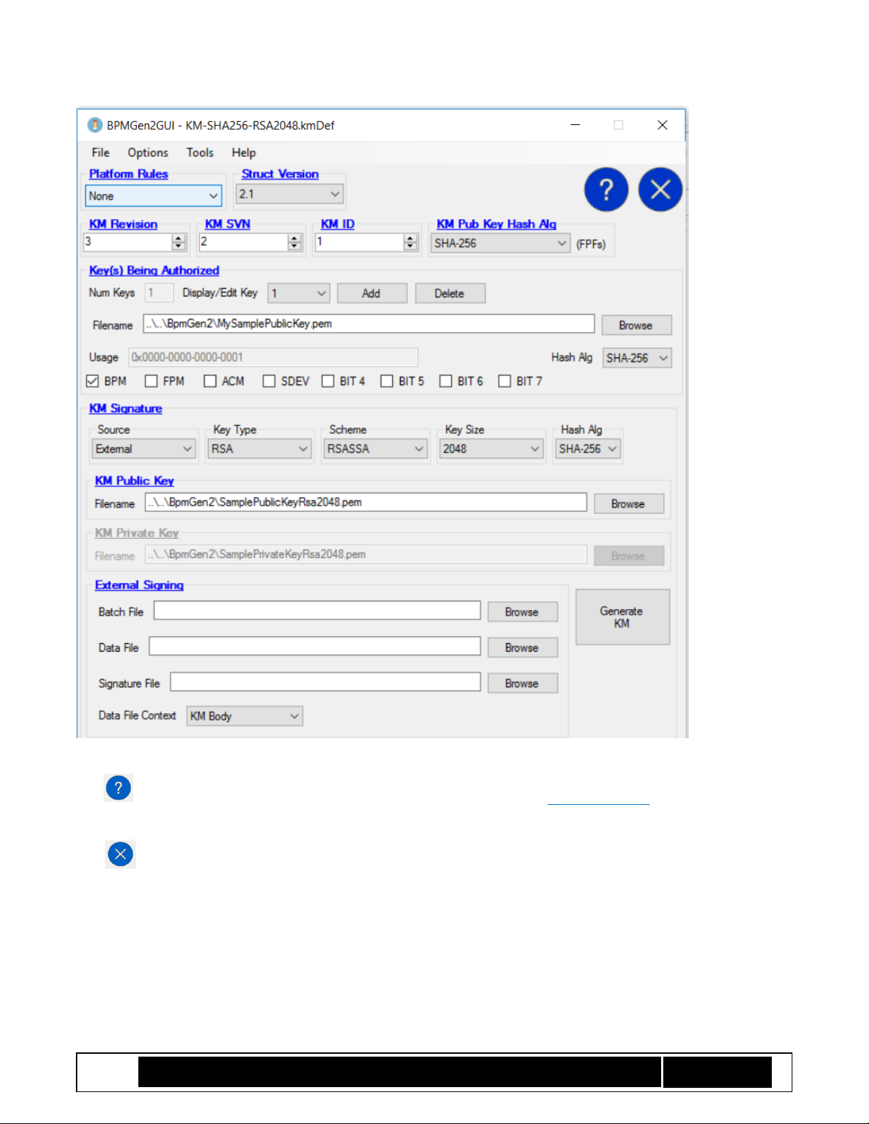
5 KM Edit Screen
The Key Manifest screen is shown in Figure 1 KM Definition Screen and the following subsections explain the
various controls and selection tradeoffs.
Page 6
Intel® TXT/BTG – BpmGen2GUI Tool User Guide
Technology Solutions Enabling Intel® TXT/BtG Tools
Page 6
Figure 1 KM Definition Screen
The button displays information about the screen. Also, clicking on a blue underlined label displays
information about that control or group of controls.
And returns you to the main screen
5.1.1 Platform Rules:
This control establishes values, limits, and ranges for the selected platform type. For example, changing the
platform type might change which hashing algorithms and signing algorithms are valid. You should select the
platform rules for which the KM will be used. See section 3.3 Platform Rules.
Page 7

Intel® TXT/BTG – BpmGen2GUI Tool User Guide
Technology Solutions Enabling Intel® TXT/BtG Tools
Page 7
5.1.2 Structure Version:
Currently all CBnT platforms only support version 2.0, while all previous platforms support only v1.0. Select the
version that the target platform supports.
5.1.3 KM Revision (0-255):
This is an arbitrary value that allows you to identify different instances of the KM. Typically, this starts at 0 and
should be incremented each time you create a new KM with the same KM ID and KM signing key. Selecting
Auto-Increment will cause the tool to automatically increment this value each time you generate the KM. For
platforms that support S3 power state, the combination of KM Revision and KM ID must be unique for all KMs
signed with the same key.
5.1.4 KMSVN (0-15)
This is used for revocation (anti-rollback) of previous KMs. This should start at 0 and only be incremented if a KM
with the previous KM SVN (for same KM ID and signing key) must no longer be allowed (i.e., revoked). Caution,
there are only 15 levels of revocation so once this counter reaches 15, you will not be able to revoke KM’s with
SVN==15.
5.1.5 KM ID (0-15):
This value must match the KMID value programmed into the platform’s chipset (FPFs), else the KM will be
considered invalid.
5.1.6 KM Public Key Hash Alg:
New for V2.1 KM. Specify the hash algorithm that was used to create the KM Public Key Hash programmed into
the platform’s chipset (FPFs).
5.1.7 Keys Being Authorized:
A v1.0 KM only authorizes BPM key. For v2.1, you can specify keys for other usages. A key that is used for
multiple usages only needs to be added once.
To add the BPM key, click “Add” button and enter the Filename or click Browse to select it. Specify the Hash
Algorithm that you want BtG to use to authenticate the BPM’s signature. The file can be a PEM file or a Binary
file containing the key, or you may specify a binary Digest file containing the hash of the public key. If PEM file or
Binary file the tool calculates the hash. In any case, you must specify the Hash Alg. Check the BPM box (and any
other appropriate box).
To add other keys, repeat this process and select their use. Only one key can have the BPM box selected. Bits 4-7
are for future use to allow you to specify usages that will be defined later.
Clicking the Delete button will remove the key being displayed.
For older platforms (V1.0) Hash Alg must be SHA256 and only the BPM key can be specified.
Page 8

Intel® TXT/BTG – BpmGen2GUI Tool User Guide
Technology Solutions Enabling Intel® TXT/BtG Tools
Page 8
5.1.8 KM Signature
You have the choice of having the KM signature generated either internally (by the tool) or externally (using
your own signing service). For either one, you need to specify the Key Type, Key Size, signing Scheme, Hash Alg,
and the KM Public Key.
Note: According to NIST, RSASSA using 2048-bit key with SHA256 is considered acceptable
through 2020 and RSASSA using 3072-bit keys with SHA384 is acceptable through 2030.
5.1.8.1 Internal Signing
To have the tool generate the signature, you select Source == Internal and need to provide the KM Public Key
and KM Private Key – then click on the Generate KM button. This will prompt you to specify the filename for the
signed KM.
5.1.8.2 External Signing
To use an external signing server, you select Source == External and need to provide the KM Public Key, name of
the Batch File, Data File, and Signature File – then click on the Generate KM button. The tool will generate an
unsigned KM saving it to Data File, then invoke Batch File. When the batch file terminates, the tool imports the
signature from Signature File, updates the KM, and prompts you to specify the filename for the signed KM.
You also have the option of having the tool output the Hash of the KM body instead of the KM body by setting
Data File Content.
The expectation is that the Batch File causes your signing server to sign Data File and return the signature in
Signature File. The format of Signature File needs to be one of the following depending on the selected
signature scheme:
For RSASSA signatures:
typedef struct {
UINT8 Signature[KeySize];
} RSA_EXTERNAL_SIG_DATA;
For ECDSA or SM2 signatures:
typedef struct { // For Alg Agility
UINT8 R[KeySize]; // R component
UINT8 S[KeySize]; // S component
} ECC_EXTERNAL_SIG_DATA;
5.1.9 Using the KM
Clicking the Generate KM button causes the tool to generate the KM and prompt you to specify the filename for
it. The output will be a binary file for you to include in the BIOS image. Note, the BpmGen2 tool can be used to
update the BIOS image with the KM (inserting it at the position indicated by FIT Type 0x0B record).
Page 9

Intel® TXT/BTG – BpmGen2GUI Tool User Guide
Technology Solutions Enabling Intel® TXT/BtG Tools
Page 9
6 Boot Policy Manifest
The BtG BpmGen2GUI tool is capable of generating a BPM Parameter file for use with the BtG BpmGen2. The
GUI tool allows you to create and save a BPM definition file (*.bpDef) that is used by the BpmGen2 tool
(typically as part of the BIOS build process to automatically create and insert an updated BPM). You should save
the bpDef file using a filename that indicates which platform the BPM is targeted (ex. GoldenEagle.bpDef).
The 3 Boot Policy Manifest edit screens are described in the following sections. And the following controls are
on each screen.
Figure 2 BPM GUI Controls
The Platform Rules control is shown on all BPM screens and has the same purpose as for the KM edit screen. It
establishes values, limits, and ranges for controls on the edit screens consistent with the selected platform type.
For example, selecting “Server” disables the VT-d BAR box because serves use GENPROT registers instead of VT-d
to protect the IBB code. See section 3.3 Platform Rules.
Struct Version allows you to select if the BPM is for older platforms (v1.0 for platforms prior to Converged BtG
and TXT). Currently all CBnT platforms support version 2.1.
The and buttons allow you to switch between BPM edit screens.
The button returns you to the main screen and the button displays information about the screen.
Also, clicking on a blue underlined label displays information about that control or group of controls.
6.1 BPM Screen 1a – BPM Header
Figure 3 BPM Definition Screen 1a – BPM Header
Page 10

Intel® TXT/BTG – BpmGen2GUI Tool User Guide
Technology Solutions Enabling Intel® TXT/BtG Tools
Page 10
6.1.1 BPM Revision (0-255):
This is an arbitrary value that allows you to identify different instances of the BPM. Typically, this starts at 0 and
should be incremented each time you ship an updated BIOS (new BPM signed with the same key). For platforms
that support S3 power state, the BPM Revision must be unique for all BPMs signed with the same key. Selecting
Auto-Increment will cause the BpmGen2 tool (not this tool) to automatically increment BPM Revision each time
it successfully generates a signed BPM.
NOTE: This value only needs to be incremented once per BIOS update, so it is recommended
that Auto Increment NOT be set during the BIOS testing and debug stages.
6.1.2 BPMSVN (0-15)
This allows you to revoke previous BPMs. This should start at 0 and only be incremented if a BPM with the
previous BPMSVN must no longer be allowed (i.e., revoked – prevents rollback). Caution, there are only 15 levels
of revocation so once this counter reaches 15, you will not be able to revoke BPM’s with SVN==15.
6.1.3 ACM SVN (0-15)
You have control over revoking Startup ACMs by setting this value. In order to revoke an ACM, this value must
match the value in the current ACM – you can only revoke ACM versions prior to the current ACM (not possible
to revoke the current ACM). When this value is equal to the current ACM’s SVN, then all previous ACMs are
revoked and will not be allowed to execute (i.e., cannot rollback to a previous BIOS with an older ACM SVN).
Setting this value to 0 results in no revocation.
6.1.4 Additional NEM Pages
BtG loads the measured IBB set into Non-Eviction Memory (NEM) to protect that code from external
modification. The Startup ACM will allocate enough NEM pages for both he measured and non-measured IBB
segments, but IBB will need a stack and might want additional pages for data it needs to protect. This value
indicates the number of additional 4K pages of NEM memory that IBB needs. The main purpose of this value is
so that the ACM can determine if there is sufficient cache memory so that the IBB and its data can be protected.
Note that the ACM sets up NEM for IBB code but only loads the measured IBB segments into NEM. IBB is
responsible for loading the Post IBB segments and setting up NEM for its stack and other data.
Caution: In addition to IBB segments and additional NEM pages, the ACM and FIT must also
fit in the processor cache. Furthermore, client processors tend to have smaller cache sizes
than server processors. So you will want to keep the number of additional pages as small as
possible, especially on client platforms and entry level servers.
6.2 BPM Screen 1b - IBB Sets
All platforms require an Initial Boot Block (IBB) Set, which specifies the segments of the BIOS code that are to be
verified by the ACM and segments (if any) that will be verified by the IBB. The set also specifies the policies for
protecting that code. Currently, there is only one set (the cold boot set). In the future there might be additional
sets (such as for resuming from S3 or for protecting memory after a surprise reset).
Page 11

Intel® TXT/BTG – BpmGen2GUI Tool User Guide
Technology Solutions Enabling Intel® TXT/BtG Tools
Page 11
Figure 4 BPM Definition Screen 1b – IBB Sets
Number of Sets indicates how many sets will be included in the BPM. To add/remove a set, select the set’s name
from the Display/Edit Set drop down menu and select or deselect Include in BPM. Current implementations
only support a single IBB Set (i.e., the Cold Boot Set). So, for all current platforms, Number of Sets, Display/Edit
Set, and Include in BPM are not enabled and only the IBB Cold Boot Set is included.
6.2.1 PBET Value
Protect BIOS Environment Timer (PBET) – indicates the time that BIOS IBB code needs before acknowledging
that it is in control. A value of 0 prevents PBET from being started. Otherwise, after the Startup ACM verifies the
Page 12

Intel® TXT/BTG – BpmGen2GUI Tool User Guide
Technology Solutions Enabling Intel® TXT/BtG Tools
Page 12
IBB measurement is valid, it starts the PBET timer and invokes the IBB code at the specified IBB Entry Point. The
IBB code signals that it is in control of the platform (e.g., controls the AP SIPI vectors) and no longer requires any
part of the BtG features or resources. BIOS signals this to the PCH by writing a 1 to BC.PBEC.StopPBET, stopping
the timer and terminating BtG.
If the timer expires, the system enters an unbreakable shutdown.
6.2.2 MCHBAR
Tells the ACM where to locate the MCH MMIO registers. Thus this is the value the Startup ACM writes to MCH
Base Address Register.
6.2.3 Flags
TPM Startup from Locality 3: When Boot Policy M-bit is set (i.e., BtG Measurement turned on), the Startup ACM
starts the TPM. The locality used to issue the TPM2_Startup command determines the initial value of
PCR0. This is recommended since it provides proof whether BtG started the chain of measurements.
Not selecting it allows PCRs to have the same measurements regardless of whether the M-bit is set (BtG
starts the TPM and makes the measurements) or M-bit is not set (thus BIOS starts the TPM from Locality
0 and performs the measurements). Note: For BPM v2.1, BpmGen2 tool will force this bit, thus it is only
optional on older platforms (BtG 1.0).
Extend into Authority PCR: When selected, instructs the Startup ACM to measure the KM and BPM public keys
into PCR7 (only if Boot Policy M-bit is set).
Leave TPM enabled on verification failure: Normally the TPM is disconnected/disabled on IBB verification error.
In some instances it is desirable to leave the TPM enabled so its resources can be used. But there is risk
since a potentially corrupted BIOS is in control, thus protections such as Physical Presence are
jeopardized and the untrusted BIOS has Platform Hierarchy authorization. So, only set this flag if it is
necessary.
Enable DMA Protection: Indicates if BtG is to protect the Platform Manufacturer’s assets by setting up and
enabling VT-d (client platforms) or using General Protection registers (server platforms). Note: For BPM
v2.1, BpmGen2 tool will force this bit, thus it is only optional on older platforms (BtG 1.0).
6.2.4 DMA Protection
The ACM can set up DMA protection to protect the BIOS and BIOS assets. This is done differently for server
platforms verses client platforms. The ACM uses VT-d on client and entry level (UP) platforms and uses General
Protection Registers (GenProt registers) on server platforms. Selecting Enable DMA Protection instructs the
ACM to setup DMA protection.
You can either specify up to 2 Base/Limit ranges or select Calculate from IBB set, in which case the ACM will
calculate a Base/Limit range to cover all the IBB segments (both measured and Post IBB segments). If Calculate
from IBB set is not selected, the ACM will use the values you specify in Base/Limit boxes. Set Base = Limit = 0
when not using that Base/Limit range. Some platforms only support a single DMA range and thus the second
Base/Limit values are not used.
Page 13

Intel® TXT/BTG – BpmGen2GUI Tool User Guide
Technology Solutions Enabling Intel® TXT/BtG Tools
Page 13
On Client platforms, you must specify the VT-d BAR (the value the Startup ACM writes to VT-d Base Address
Register) so the ACM can program the PMR registers of the VT-d engine.
For servers, the values in the DMA Protection boxes will be programmed into GenProt registers. Typically
GenProt0 and Genprot1, but check your specific platform’s specification. It is a simple task for BIOS to detect
which registers were used.
If Calculate from IBB Set is selected, then the BpmGen2 tool will calculate the first Base and Limit values to
cover all of the IBB code (and the second base/limit will not be used).
6.2.5 IBB Entry Point
Specifies the first byte of IBB code that will be executed when the IBB verification passes. If IBB verification fails
and Boot Policy enforcement allows BIOS to execute, BIOS will be invoked at the legacy reset vector.
6.2.6 IBB Segment Source
The BpmGen2 tool allows the user to manually specify IBB segments. This gives the user control over whether or
not segments are to be included in the IBB hash calculation, and the cache type of the segment (Write Protect or
Write Back). The tool can also automatically determine IBB segments either by processing FIT Type 7 records or
by processing a BIOS Info Table in the BIOS image file. Processing FIT records will only produce Measured IBB
segments while processing the BIOS Info Table can result in both measured IBB segments and Post IBB segments
(Post IBB segments are measured/verified by BIOS instead of ACM).
To use the BIOS Info Table, you must provide the GUID. The BpmGen2 tool searches the BIOS file for that GUID
to find the BIOS Info Table.
6.2.7 IBB Hash Alg
Specify the hash algorithms used to create the digest of IBB segments measured by the ACM and the IBB
segments not measured by the ACM (Post IBB segments). If there are no Post IBB segments, select “None” for
IBB segments not measured by ACM.
6.2.8 Post IBB Hash
You can have the BpmGen2 tool calculate the Post IBB hash digest or import it from a file. Since BtG does not
use the Post IBB Hash value, there is no restriction on how BIOS uses it, but it must be the size of the Post IBB
hash digest (per IBB Hash ALG for IBB segments not measured by ACM).
6.3 BPM Screen 2A – TXT Element
Page 14

Intel® TXT/BTG – BpmGen2GUI Tool User Guide
Technology Solutions Enabling Intel® TXT/BtG Tools
Page 14
Figure 5 BPM Definition Screen 2A – TXT Element
On this screen you specify policies for Intel TXT. This information is optional and the TXT Element may be
excluded from the BPM, in which case the ACM will use the default values.
6.3.1 Include
TXT Element is optional. Check this box to include the TXT Element from the BPM. If not included, the ACM uses
default values.
6.3.2 TXT Execution Profile
Client and server TXT models are converging, but there are several operational differences between platforms
based on (a) client hardware (i.e., client processors and chipsets) including entry level servers using client
processors and (b) enterprise class server platforms based on server processors and chipsets. Main differences
are:
1. Whether BIOS is trusted to ensure un-aliased memory configuration (Server) or if BIOS is required to
call ACHECK for ACM to do alias checking (Client).
2. The Client Profile does not include cold boot BIOS as part of the MLE TCB since it doesn’t rely on it to
provide any assurance for the sake of MLE launch. This speeds-up execution by not measuring any of
the BIOS parts into dynamic PCRs. The BIOS Scrubbing Code is still part of MLE TCB since MLE trusts it
to scrub memory in case of an unexpected reset. But since BIOS scrubbing code is verified, there is no
need to measure its entirety into dynamic PCRs. Instead it is measured indirectly as part of BPM
signature extend.
3. The Server model does include cold boot BIOS code as part of the MLE TCB. Thus the Startup ACM
computes BIOS Integrity values and saves them in the in AUX Index for the SINIT ACM to extend into
Dynamic-PCRs.
Page 15

Intel® TXT/BTG – BpmGen2GUI Tool User Guide
Technology Solutions Enabling Intel® TXT/BtG Tools
Page 15
The first one is the most important because BIOS must behave differently. Historically, ACMs have been
designed to be either a client or server ACM. As the technology advances, client and server requirements are
converging, allowing a single ACM design to support both client and server models. For this case the ACM
automatically detects if the platform has client or server hardware. The TXT Execution Profile selection allows
you to override the automatic selection and force the ACM behavior.
The server profile is also considered to be the Unified profile. That is client ACMs have the option of behaving as
a legacy client ACM or as server ACM.
Select Default to allow the ACM to detect based on platform hardware. Select Unified to force the ACM to
follow the unified server operation, and select Client to force the ACM to follow the client operation.
Not all platforms allow override and selecting a profile that is not supported by the ACM is an error.
6.3.3 Secrets Scrubbing Policy
The OS can set a Secrets flag after a successful measured launch (i.e., MLE is active) indicating it wants the
platform to protect secrets and sensitive information it might have in memory in case of an unexpected reset.
When there is an unexpected reset and the Secrets flag is set, the ACM makes sure the scrubbing process
completes. Typically, the BIOS is responsible for scrubbing the memory, and then calling the ACM to clear the
Secrets flag.
The default policy is “only Trust Verified BIOS to scrub memory”. If IBB verification fails, then the ACM will
execute the backup scrubbing method. When BIOS is trusted to scrub memory, if BIOS incurs an error in its
attempt to scrub memory, it can request the ACM to perform the backup scrubbing method.
You have the option to instruct the ACM to Always Trust BIOS. In which case the ACM will only perform the
backup scrubbing method if requested by the BIOS. This may be desired when there are other protections in
place, such as data in system memory is encrypted (e.g., secure enclaves/SGX).
You also have the option to instruct the ACM to Trust No BIOS. In which case the ACM will always perform
backup scrubbing when Secrets flag is set. Typically this is only selected on platforms that support memory
depletion power down scrubbing process.
6.3.4 Backup Policy
There are two fallback methods the ACM can use when BIOS cannot scrub memory.
• Memory depletion power down scrubbing process - The ACM powers down the platform for a time
sufficient to cause significant memory loss. The ACM programs the platform to wake after an interval
sufficient to assure memory content has been lost and then powers down the platform. Once the ACM
verifies the platform had powered down for the expected time, the ACM clears the Secrets flag and
allows memory to be enabled.
• Unbreakable shutdown – The ACM enters an unbreakable shutdown to prevent access to system
memory.
• PFR Recovery – If the platform supports PFR (Platform Firmware Resiliency), upon TXT measurement
failure, the platform will fall back into T-1 and perform a firmware recovery.
Page 16

Intel® TXT/BTG – BpmGen2GUI Tool User Guide
Technology Solutions Enabling Intel® TXT/BtG Tools
Page 16
Not all platforms support the Memory depletion power down scrubbing process.
6.3.5 Reset Aux Control
For TPM 2.0 devices, it may be necessary to delete the AUX Index when refurbishing a platform. The AUX Index
can only be deleted by the ACM and the ACM must be instructed to do so by the OEM.
So to instruct the ACM to delete the AUX Index you have to create a BPM with a TXT Element where Reset Aux
Control is set to Delete AUX. And then, the BIOS must leave the Platform Hierarchy authValue (aka
PlatformAuth) empty and invoke the Reset AUX function (GETSEC ENTERACCS leaf).
For normal TXT operation, the Reset Aux Control Delete AUX box has to be unselected, in which case invoking
the ACM Reset AUX function causes the ACM to clear the AUX Index to a virgin state as if the platform had never
before performed a measured launch.
6.3.6 Minimum SVN Version
The minimum SINIT version authorized by the OEM to run on the platform.
6.3.7 Memory Depletion Power Down Interval
If the ACM supports the “memory depletion power down scrubbing” process, you provide the information that
the ACM needs to perform that process. The ACM uses ACPI functions to power down the platform, but since
the ACM executes before BIOS configures the ACPI register, you have to provide the information the ACM
needs.
6.3.7.1 ACPI Base
ACPI Base Offset – Value the ACM programs into PCI configuration register BAR2 of device Bus 0 : Device 31 :
Function 2 : Register 0x20 to map fixed ACPI IO registers into IO bus. Default is 0x400.
6.3.7.2 PWRM Base
PWRM BASE Offset - Value ACM programs into PCI configuration register PWRMBASE of device Bus 0 : Device
31 : Function 2 : Register 0x10 to map fixed ACPI MMIO registers into memory bus. Default is 0xFE000000.
6.3.7.3 Power Down Interval
The ACM’s default time is sufficiently long enough to deplete any memory technology. New memory
technologies tend to have quicker depletion times. If you know the memory depletion time for the memory type
installed in the platform you may want to change the timeout value to be more robust.
You may use the ACM default power down interval by checking the Use ACM Default box or you may specify the
time specifying Minutes and/or Seconds (10 minutes max).
6.3.7.4 PTT:CMOS
For confirming that the platform had powered down for the entire memory depletion power down interval (i.e.,
not powered back on early), the ACM stores the system time in the AUX Index.
Page 17

Intel® TXT/BTG – BpmGen2GUI Tool User Guide
Technology Solutions Enabling Intel® TXT/BtG Tools
Page 17
However, platforms that use Intel Platform Trust Technology (PTT, aka firmware TPM), the ACM cannot use the
AUX index. This is because the firmware TPM is not fully functional until after BIOS initializes memory, and BIOS
does not execute until after completing the power down process. Thus the ACM needs another form of nonvolatile memory to save the system time. The alternative is to use two bytes of CMOS memory in the RTC well.
Here you indicate the offset for the 2 bytes.
You need to specify two bytes of CMOS RAM in Bank 0 that are not used otherwise (i.e., in the range of 14-127)
and they do not need to be contiguous. These locations are not used when the platform has a discrete TPM.
6.3.8 TXT Cold Boot Set
This defines the portion of BIOS that is included in the TXT TCB. Currently it is required to be the same as the IBB
Cold Boot Set specified on screen 1.
6.3.8.1 Source
Currently must be “Use IBB Cold Boot Set”
6.3.8.2 Hash Alg
Not used when using IBB Set.
6.3.8.3 GUID
Not used when using IBB Set.
6.4 BPM Screen 2B –Platform Configuration Element
This is an optional element that is used when the ACM supports Memory Depletion Power-down scrubbing
policy. It tells the ACM where to locate BIOS request to invoke the Memory Depletion Power-down sequence.
Figure 6 BPM Definition Screen 2b – Platform Configuration
Page 18

Intel® TXT/BTG – BpmGen2GUI Tool User Guide
Technology Solutions Enabling Intel® TXT/BtG Tools
Page 18
6.4.1 Power Down Request Location
Previously it was mentioned that BIOS can make a request to the ACM to perform Memory Depletion Power
Down Scrubbing. The BIOS needs to write an indication to a non-volatile memory location that the ACM
inspects. There are two options:
• CMOS Memory – you specify 3 bits in CMOS memory
• TPM NV Index – you specify 3 bits in a TPM NV Index.
o For platforms that support TPM1.2, TPM2.0, and/or PTT, you specify the NV Index for each. If
any of these are not supported by your platform, you may set the Index handle to zero or just
leave the default values (the values are only used when the platform contains that type of
TPM).
The default value for the 3 bits is 000b and when BIOS wants to invoke the Memory Depletion it writes a value
and issues a platform reset. The value that BIOS sets depends on the reason for the request. In case of a
scrubbing error BIOS can write 001b to request unconditional Memory Depletion Power Down process. BIOS
might also provide the means for the user to request the Memory Depletion Power Down process in which case
it would set 010b (and issue a platform reset).
If the platform supports the “TCG Platform Reset Attack Mitigation” specification, then the MOR interface would
set 100b (and issue a platform reset).
The ACM will clear the 3 bits back to 000b after the Power Down process completes.
6.4.2 CMOS
Index Register Addr and Data Register Addr indicates I/O offsets that the ACM uses to access the CMOS
memory. Index Offset is the value that the ACM writes to Index Register Addr. Must be unused byte in bank 0
(i.e., value between 14::127)
6.4.3 TPM NV Index
You need to provide the NV Index handle that can be read and written using an empty authValue and accessible
by at least localities 0 and 3. The last byte of the SGX index meets this requirement.
If PTT is used to hold PD_Request variable, the following restriction applies: index must be selected from the
0x1C1_0100∷0x1C1_010F subset of “Intel Reserved” range. Again, the SGX index satisfies this requirement.
6.4.4 Data File
This is used for additional data to be measured by the ACM. The ACM will measure this data, but does not parse
or process the contents.
Page 19

Intel® TXT/BTG – BpmGen2GUI Tool User Guide
Technology Solutions Enabling Intel® TXT/BtG Tools
Page 19
6.5 BPM Screen 3A –Platform Manufacture’s Element
Figure 7 BPM Definition Screen 3a
This is a completely optional element that provides the means for you to pass arbitrary data to the BIOS (or any
other entity that can read the BPM). This information is not used by Intel BtG nor Intel TXT.
To include this element, just check the Include box and specify the filename of the data to be included.
6.6 BPM Screen 3B – BPM Signature
Figure 8 BPM Definition Screen 3b
This screen is very similar to the KM Signature screen, however, the BPM signature is created when the
BpmGen2 tool executes (not by the BpmGen2Gui tool).
Page 20

Intel® TXT/BTG – BpmGen2GUI Tool User Guide
Technology Solutions Enabling Intel® TXT/BtG Tools
Page 20
BPM signatures can be generated either internally (by the BpmGen2 tool) or externally (using your own signing
service). For either one, you need to specify the Hash Alg, the Key Type, Key Size, and the signing Scheme of the
signature. Note, the BpmGen2 tool can be used to update the BIOS image with a new BPM (as located by FIT
Type 0x0C record) or just generate a binary file that for manual insertion. Refer to the BpmGen2 tool’s user
guide for more information.
6.6.1 Internal Signing
To have the BpmGen2 tool generate the signature you need to provide the BPM Public Key and BPM Private
Key. Most PEM private key files contain the public key. If that is the case then you can leave BPM Public Key
filename empty and the tool will extract the public key from the private key.
6.6.2 External Signing
To use an external signing server, you need to provide the BPM Public Key, name of the Batch File, Data File,
and Signature File.
For external signing, the BpmGen2 tool will generate an unsigned BPM and save it to Data File, then invoke
Batch File. The expectation is that the Batch File causes the signing server to sign Data File and return the
signature in Signature File. The format of Signature File needs to be one of the following depending on the
selected signature scheme:
For RSASSA signatures:
typedef struct {
UINT8 Signature[KeySize];
} RSA_EXTERNAL_SIG_DATA;
For ECDSA or SM2 signatures:
typedef struct { // For Alg Agility
UINT8 R[KeySize]; // R component
UINT8 S[KeySize]; // S component
} ECC_EXTERNAL_SIG_DATA;
As an option, you can have the BpmGen2 tool calculate the hash of the BPM body and write it to the Data File
(instead of writing the BPM body). This is selected via the Data File Context drop-down menu.
6.7 Save Def Button
Clicking on the Save Def button on screen 3 will save the information on all screens as a BpmParams file
(*.bpDef). This parameter definition file can be used with the BpmGen tool and can also be edited by this tool.
Page 21

Intel® TXT/BTG – BpmGen2GUI Tool User Guide
Technology Solutions Enabling Intel® TXT/BtG Tools
Page 21
Appendix A BpmParams File
A typical BPM Parameter file (*.bpDef) is shown below.
# FILEHEADER
FileID: _BPMDEF_
FileVersion: 1
ToolVersion: 3
ToolDate: 20180122
FileDate: 20180123
//
# BPM_DEF
PlatformRules: Server
BpmStrutVersion: 0x21
BpmRevision: 0
BpmRevocation: 0
AcmRevocation: 0
NEMPages: 0x4
IbbSetCount: 1
CurrentIbbSet: 0
//
# IBB_SET
IbbSetType: 0:ColdBoot
IbbSetInclude: TRUE
PBETValue: 0xF
MCHBAR: 0x00000000FED10000
VTD_BAR: 0x00000000FED90000
DmaProtBase0: 0x0
DmaProtLimit0: 0x0
DmaProtBase1: 0x0
DmaProtLimit1: 0x0
IbbFlags: 0x3
// Bit0 : Enable DMA Protection;
// Bit1 : Issue TPM Start-up from Locality 3;
// Bit2 : Extend Authority Measurements into the Authority PCR;
// Bit3 : On error: Leave TPM Hierarchies enabled. Cap all PCRs;
// Bit4 : Top Swap Supported;
DmaProtAutoCalc: FALSE
IbbHashAlgID: 0x0B
IbbEntry: 0xFFFFFFF0
PostIbbHashAlgID: 0x0B
PostIBBHashSource: Calculate
PostIbbHashFile:
IbbSegSource: FIT
IbbSegFile:
IbbGuid: 4a4ca1c6-871c-45bb-8801-6910a7aa5807
ObbHashAlgID: 0x0B
ObbHashSource: Base to IBB[0]
ObbHashFile:
ObbGuid: 00000000-0000-0000-0000-000000000000:Test
ObbGuid: 00000000-0000-0000-0000-000000000001:Test2
//
Page 22

Intel® TXT/BTG – BpmGen2GUI Tool User Guide
Technology Solutions Enabling Intel® TXT/BtG Tools
Page 22
# TXT_ELEMENT
TxtInclude: TRUE
TxtFlags: 0x0
// [4:0] = TXT execution profile
// 00000b – Use Default based on HW
// 00001b - Server Profile
// 00010b - Client Profile
// [6:5] = “Memory scrubbing” policy
// 00b - Trust Verified BIOS
// 01b - Trust Any BIOS
// 10b - Trust No BIOS
// [8:7] = Backup Policy
// 00b - Default
// 01b - Power Down
// 10b - Unbreakable Shutdown
// [31] = Reset AUX control (1=AUX Reset leaf will delete AUX Index)
//MemoryDepletion Power Down
AcpiBase: 0x400
PwrmBase: 0xFE000000
PdUseDefault: FALSE
PdMinutes: 5
PdSeconds: 0
PttCmosOffset0: 0x7E
PttCmosOffset1: 0x7F
//TXTE Segments
TxtSegSource: IBB
TxtSegGuid: 4a4ca1c6-871c-45bb-8801-6910a7aa5807
TxtSegHashAlgID: 0x10
//
# PLATFORM_CONFIG_ELEMENT
PcdInclude: TRUE
PdReqLocation: TPM
// Power down request location for CMOS
CmosIndexRegister: 0x70
CmosDataRegister: 0x71
CmosIndexOffset: 125
CmosBitFieldWidth: 3
CmosBitFieldPosition: 0
//
# TPM1.2_LOCATION
TpmIndexHandle: 0x50000004
TpmByteOffset: 7
TpmBitFieldWidth: 3
TpmBitFieldPosition: 0
//
# TPM2.0_LOCATION
TpmIndexHandle: 0x1C10104
TpmByteOffset: 7
TpmBitFieldWidth: 3
TpmBitFieldPosition: 0
//
# PTT_LOCATION
TpmIndexHandle: 0x1C10104
Page 23

Intel® TXT/BTG – BpmGen2GUI Tool User Guide
Technology Solutions Enabling Intel® TXT/BtG Tools
Page 23
TpmByteOffset: 7
TpmBitFieldWidth: 3
TpmBitFieldPosition: 0
//
# PLATFORM_MANUFACTURERS_ELEMENT
PmdeInclude: FALSE
PmdeFile:
//
# BPM_SIGNATURE
BpmSigSource: Internal
BpmSigHashAlgID: 0x0B
BpmSigKeyType: 0x01
BpmSigScheme: 0x14
BpmKeySizeBits: 2048
BpmSigPubKey: MySamplePublicKey.pem
BpmSigPrivKey: MySamplePrivateKey.pem
BpmSigBatch:
BpmSigData:
BpmSigDataType: BPM Body
BpmSigXSig:
//
#EOF
 Loading...