

Page 1

Intel® Security Technologies
BpmGen2 User Guide
Revision 0.9
Last updated September 21, 2020
Important Changes and Updates:
Oct 2, 2016 Initial Draft
Nov 15, 2016 Added new features – KM Gen & ability to display BPM and Key manifests
Feb 21, 2017 Added Quick Start Guide
Mar 17, 2017 Updated to support legacy (v1.0) platforms (such as SKL/SKX)
May 30, 2017 Updated to support BFX (Block boot)
Oct 5, 2017 Updated for new BPM & KM Structures and added features
Dec 7, 2017 Updated for new features and BtG requirement changes
Mar 5, 2020 Updated for numerous architecture changes
Sep 21, 2020 Added information on -REMAP argument, see section 6
Note: BpmGen2 is significantly different from and not backward compatible with the original
BpmGen tool.
This toolkit is provided “as is” with no express or implied warranty and thus it is the user’s
responsibility to verify proper functionality.
1 Introduction
1.1 Scope
The purpose of this document is twofold:
• Describe how to use the BpmGen2 tool
• Provide the OEM (Platform Architect and BIOS Developer) with information on how to best configure
the BPM and explain the impact of those settings on Intel® Boot Guard and Intel® Trusted Execution
Technology.
The first time you read this document you should read (at least browse through) the entire document.
Chapter 1 “Introduction” is a short introduction to the tool’s capability.
Page 2

Intel® TXT/BTG – BpmGen2 Tool User Guide
Technology Solutions Enabling Intel® TXT/BtG Tools
Page 2
Chapter 2 “BpmGen2 Tool Fundamentals” explains how to use the tool.
Chapter 3 “BPM PARAMS File” explains how to edit the BPM Parameter file and provides guidance on
various settings. However some topics require more detailed discussion, thus the following chapters and
Annexes.
Chapter 4 “Understanding Your Role and Responsibilities” provides a more detailed guide for setting
required components.
Chapter 5 “Power Down Memory Depletion” provides a guide to using a new Intel TXT capability – Power
Down Memory Depletion backup method for scrubbing memory.
Chapter 6 “Boot from Block” explains how to produce a BPM for booting from a block media device.
Chapter 7 “OBB Hash” explains how the BpmGen2 tool can calculate OBB Hash measurements
Appendix A “BpmGen2GUI Tool” provides an introduction to the BpmGen2GUI tool.
Appendix B “Recommendations” provides recommendations and tutorials on using the tools.
1.2 Overview
Intel© has converged Intel Trusted Execution Technology (Intel© TXT) with Intel© Boot Guard Technology (Intel©
BtG) merging redundant structures into the Boot Policy Manifest (BPM). Specifically, some of the information
that the OEM previously provided in the Firmware Information Table (FIT), in the TPM PS Index, and PS Policy
the OEM now provides in the Boot Policy Manifest (BPM). In addition, new features have been added and the
OEM establishes policies for these features via the BPM. This integration is referred to herein as Converged Intel
BTG/TXT (CBnT).
To support either Intel TXT or Intel BtG, the OEM is responsible for producing a Key Manifest (KM) and Boot
Policy Manifest (BPM) and including them in the BIOS image. These manifests are locatable via FIT type 0x0b and
0x0c records. The BPM must be regenerated for each BIOS update.
The BPMGen2 Toolkit consists of several tools:
• The BPMGen2 tool is a Windows DOS based application designed to generate the Boot Policy Manifest
(BPM) and can be used in a batch file to automatically update the BIOS image with the new BPM. It can
also generate a Key Manifest.
• The BpmGen2GUI is a Windows GUI based tool that will generate the BPM Parameters file needed for
the BpmGen2 tool and can also generate a Key Manifest (KM).
For Converged Intel BTG/TXT the BPM was enhanced to include new structures and the KM was modified to
support KM public Key Hash algorithm agility and add the ability to authenticate multiple keys. The BPM and KM
can support RSA and SM2 signing (in preparation for ACMs that support SM2).
When using the BpmGen2 tool to build a new BPM, instead of having a long complicated command line required
for the old BpmGen tool, you now provide a BPM parameters file (aka: Bpm Params). The Bpm Params file
contains parameters that typically don’t change from build to build. The Bpm Params file is a text file of
particular format. You can use the BPMGen2GUI tool to build the Bpm Params file or you can simply edit an
existing Bpm Params file.
Page 3

Intel® TXT/BTG – BpmGen2 Tool User Guide
Technology Solutions Enabling Intel® TXT/BtG Tools
Page 3
✓ Chapter 2 explains how to use the BpmGen2 tool
✓ Chapter 3 provides specifics on editing the Bpm Params file
✓ The remaining chapters and appendixes provide details on specific features.
1.3 Tool Capabilities
The BpmGen2 tool is capable of:
• Generating a new v2.1 BPM
• Generating a new v2.1 KM
• Generating a legacy 1.0 BPM
• Generating a legacy 1.0 KM
• Updating the Firmware file with the new BPM and KM
• Displaying a BPM or KM
• Displaying the BtG components of a Firmware file (FIT, BPM, KM), and the key hashes
• Internal or external BPM/KM manifest signing
o RSASSA Pkcsv1.5 and RSASSA_PSS
o ECC-P256 and ECC-P384
o SM2
• Supporting the following Hash algorithms:
o SHA256
o SHA384
o SHA512
o SM3
o SHA1
• Prepending Boot Partition Descriptor Tables to the Firmware file (for BFX)
• New operations added to support other manifests:
o Hashing a file (0r a portion of a file)
o Signing a file
o Extracting the public key from a PEM file
The BpmGen2GUI tool is capable of:
• Generating the BPM Parameter file (*.bpDef) used by the BpmGen2 tool
• Generating a new v2.1 KM
• Generating a legacy 1.0 KM
• Internal or external KM manifest signing
o RSASSA Pkcsv1.5 and RSASSA_PSS using SHA256,SHA384, SHA512
o SM2 using SM3
Page 4

Intel® TXT/BTG – BpmGen2 Tool User Guide
Technology Solutions Enabling Intel® TXT/BtG Tools
Page 4
1.4 References
Table 1 Reference Documents
Document/Toolkit
Document No. /Location
[1] “Intel® BTG/TXT Server BIOS Specification”
IBL/CDI Doc# xxxxxx
[2] “Intel® BTG/TXT Server Design Guide”
IBL/CDI Doc# xxxxxx
[3]
[4]
1.5 Terminology
Term
Description
ACM
Authenticated Code Module: Platform specific code created and signed by Intel. An ACM
is authenticated by hardware and executed in an isolated environment within the
processor.
Authentication
A cryptographic method of verifying both integrity and ownership of a binary module. A
module signed with a private / public key pair can be cryptographically authenticated.
Also, matching a cryptographic hash measurement of a module to a known good
measurement.
BIOS ACM
BtG ACM
Startup ACM
An Intel provided ACM the OEM includes in the BIOS image. A portion of the ACM
(referred to as Startup ACM or BtG ACM) executes before BIOS, contains BtG policy
engine, and verifies BIOS code. For Intel TXT, the BIOS ACM is also invoked later by BIOS
to perform certain security checks and functions. The terms Startup ACM, BIOS ACM,
and BtG ACM refer to the same module.
BPM
Boot Policy Manifest – a structure signed by the OEM that establishes policies for Intel
BtG and Intel TXT.
BPM
Administrator
A person (or persons) that has the authority to sign a BPM using a particular signing key.
There can be a different BPM administrators for different projects and the Key Manifest
for a particular project specifies which key, and therefore which BPM administrator, is
valid for the that project.
Converged
BtG/TXT
(CBnT)
Intel BtG converged with Intel TXT. These two technologies now share common
structures.
Page 5

Intel® TXT/BTG – BpmGen2 Tool User Guide
Technology Solutions Enabling Intel® TXT/BtG Tools
Page 5
Term
Description
DPR
DMA Protected Range – a region of system memory that is blocked to I/O device’s
memory accesses to prevent I/O devices from gaining access to Intel TXT restricted
memory.
FIT
Firmware Interface Table – A data structure embedded in BIOS so that Intel microcode
and ACMs can locate BIOS components.
KM
Key Manifest – a structure signed by the OEM that establishes the validity of the key
used to sign BPM. Each platform is permanently configured with a KM_ID plus the hash
of the KM public signing key such that only a KM with the same KM_ID and signed with
the matching private key will be considered valid.
KMID
Key Manifest Identifier – KMID values are arbitrarily assigned by the OEM and typically
used as a project ID to control which BPM administrator is allowed to sign the BPM for
that project.
KM
Administrator
A person (or persons) that has the authority to sign a KM. The role of the KM
administrator is to manage which BPM signing key, and therefore which BPM
administrator, is authorized for a particular project.
Measurement
A cryptographic fingerprint of a binary module. Also called hash or digest. Hashing a
binary module using a hash algorithm like SHA256 produces a unique hash digest value
(the module’s measurement). It is not possible to derive the original binary from the
hash bytes.
ME/SPS
Management Engine/Server Platform Services – Intel® Server Platform Services (Intel®
SPS) firmware running in Intel® Management Engine (Intel® ME) microcontroller present
in the chipset to perform security and other system functions.
NEM
Non-Eviction Mode
PCR
Platform Credential Registers -- Dedicated registers in the TPM (sometimes referred to
as Platform Configuration Registers).
PS Index
Obsolete “platform supplier” TPM NV Index where platform vendor set TXT Policies.
Now vendor TXT policies are specified in the BPM.
Startup ACM
See BtG ACM.
TCB
Trusted Computing Base – Includes all the elements capable of modifying/protecting the
platform’s configuration.
TPM
Trusted Platform Module – a hardware device defined by the TCG that provides a set of
security features used by Intel TXT and Intel BtG.
Page 6
Intel® TXT/BTG – BpmGen2 Tool User Guide
Technology Solutions Enabling Intel® TXT/BtG Tools
Page 6
Term
Description
Intel TXT
Intel Trusted Execution Technology.
VT-d
Virtualization Technology for Directed I/O – hardware support component of Intel®
Virtualization Technology for managing DMA and interrupts generated by I/O devices.
2 BpmGen2 Tool Fundamentals
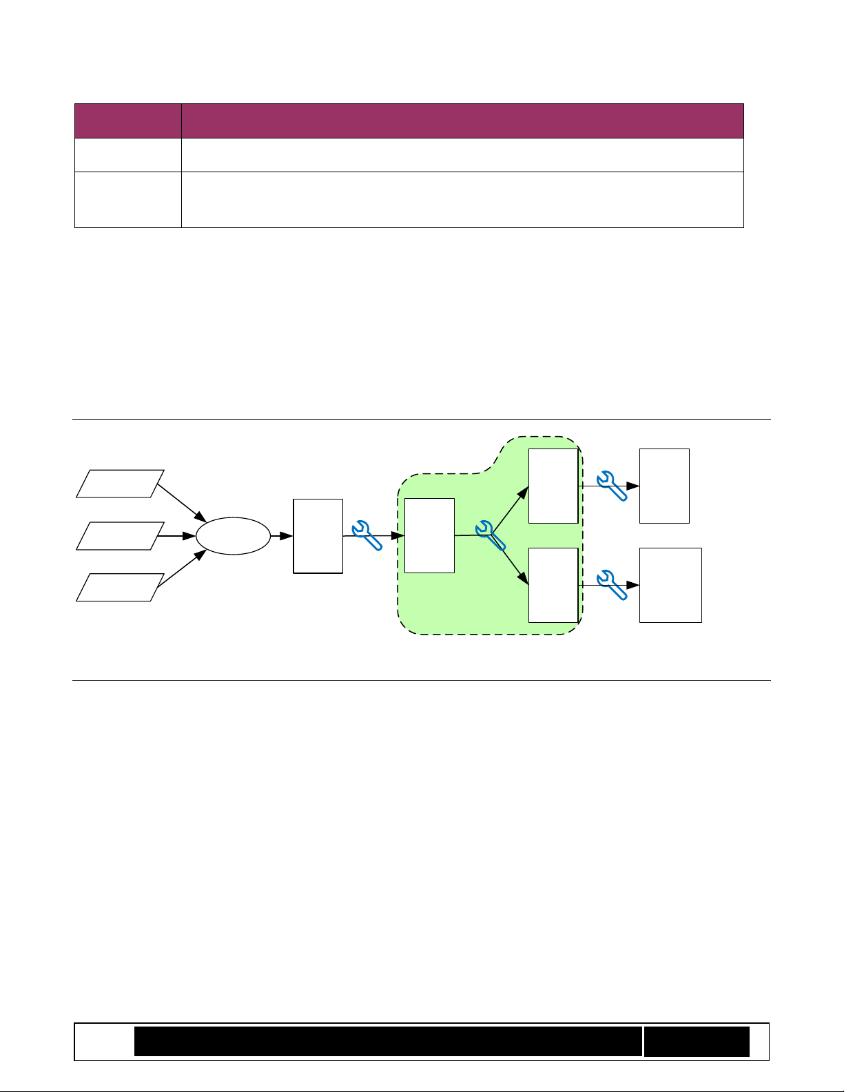
The BpmGen2 tool’s primary purpose it to take your initial BIOS file (after it has been updated with a Firmware
Interface Table (FIT)), create a Boot Policy Manifest (BPM) signed by you, insert that BPM into the BIOS image
and save the updated BIOS image to a file that can be used to create a SPI Flash device or a file that can be used
to create a Boot Partition file (for platforms booting from a block media device).
Initial
BIOS
File
Signed
BIOS
for
Flash
Signed
BIOS
for
Block
Fixed-
up
BIOS
File
Compiler
BIOS
files
Data
Drivers
FitGen
Tool
BpmGen2
Tool
Flash
Image
Boot
Partition
File
Scope of this
document
MEU &
FIT Tool
MEU &
FIT Tool
Booting
from SPI
Flash
Booting
from
Block
Device
Figure 1 Tool Chain
2.1 Getting Started
The BpmGen2 tool has many options. This section provides an overview on using the most common features.
See Appendix B “Recommendations” for some advanced topics and hints on how to better use the tool.
This tool (BpmGen2) generates the Version 2 BPM (for platforms that support converged BtG/TXT).
Older platforms require a Version 1 BPM. The BpmGen2 tool is also capable of generating a v1 BPM,
which is a subset of Version 2.
The BPM must be updated for each BIOS release. The BpmGen2 tool is designed to do that as part of a
batch file that you run to build the BIOS (i.e., build BIOS image, generate the FIT, then use this tool to
update BPM).
You must reserve space for the BPM in your BIOS image (via FIT Type 0xC record) that is at least as large
as your actual BPM. There are a number of factors which affect BPM size (see Table 2 Typical Manifest
Sizes). FYI: An example BPM signed with a 3072-bit RSA key using SHA384 can be 1341 bytes plus the
size of any Platform Manufacture’s data that you wish to add.
Page 7

Intel® TXT/BTG – BpmGen2 Tool User Guide
Technology Solutions Enabling Intel® TXT/BtG Tools
Page 7
The tool can
matically replace that dummy BPM with your actual BPM.
There is a companion tool (BpmGen2GUI) that builds a parameter file used by this tool, or you can
manually edit one of the sample parameter files (*.bpDef).
Typically, the parameter file does not change from build to build. However, you might want to use a
different parameter file during debug than for the final production worthy BIOS.
The BpmGen2 tool is capable of also replacing the KM. Typically, the KM does not change from build to
build. So you may want to just imbed the actual KM in the original BIOS image.
You can either use this tool or the BpmGen2GUI tool to produce your KM.
Both the KM and BPM must be signed. The tools can generate the signature or you can use an external
signing service.
The key used to sign the KM is considered a master key, because the KM authorizes the key that signs
the BPM as well as keys for other manifest. See Annex B.2 “Master and Subordinate Keys” for more
information.
The manufacturing process must program the hash of the KM Public signing key into the chipset’s Field
Programmable Fuses (FPFs). The BpmGen2 tool can calculate/display the KM Public signing key hash
value.
Using a different key for signing the BPM (than for signing the KM) allows you to authorize different
BIOS authorities. That is, each BIOS developer/provider can have their own key, which a KM
administrator is able to revoke if needed.
Typically you will need to:
1. Use either the BpmGen2 tool or the BpmGen2GUI tool to build one or more Key Manifests
2. Use the BpmGen2GUI to create/edit your BPM Parameters file
3. Use the BpmGen2 tool to create the BPM and update your BIOS image
2.2 Capabilities
The BPMGen2 tool can:
• Generate a KM based on command line arguments and save it to a file.
• Generate a BPM based on the specified BIOS image and your BPM Parameter file:
o save the BIOS image updated with the new BPM (and optionally a specified KM)
o save the new BPM to a file to be manually imported into the BIOS
• Display the FIT/BPM/KM information for a specified BIOS image.
• Display a BPM or KM given a BPM or KM file.
And in support for generating other manifests, the tool can:
• Generate the hash digest of a file (or portion of the file)
• Generate a signature of a file (or portion of the file)
• Extract the binary public key form a PEM file
A BPM must be signed and the tools support both internal and external signing.
Note: Supported algorithms and key sizes vary by platform. Please check platform requirements
Page 8
Intel® TXT/BTG – BpmGen2 Tool User Guide
Technology Solutions Enabling Intel® TXT/BtG Tools
Page 8
The tool supports the following hashing algorithms:
• SHA256
• SHA384
• SHA512
• SM3
The tools supports the following signing algorithms:
• RSASSA-PKCS v1.5 signatures with 2048 and 3072 bit keys
• RSASSA-PSS signatures with 2048 and 3072 bit keys
• ECDSA signatures with:
o NIST P256 Curve (256-bit key) w/ SHA256, SHA384, & SHA512
o NIST P-384 Curve (384-bit key) w/ SHA384, & SHA512
o Chinese SM2 Curve (256-bit key) w/ SM3
Note: The set of allowed signature schemes is platform specific. Currently, RSASSA-PKCS v1.5 is supported on all
platforms, but check your platform requirements
2.3 BIOS Requirements
The BIOS image must include a Firmware Interface Table (FIT).
FIT Pointer must be at 0xFFFFFFFC (0x40 below Top of Low Memory).
FIT must include a Type 0x0b (KM) record and a Type 0x0c (BPM) record.
Size indicated in those records must be large enough to fit the new manifests.
2.4 Manifest Sizes
The size of the BPM and KM will vary with the selected hash algorithms, signing key type, and key size. The size
of the BPM also has a number of variable sized elements:
• IBB Element contains a variable number of segments (12 bytes per segment), 8 segments max
• TXT Element (optional) – in the future the TXT Element might include a variable number of segments
• Platform Config Data Element (optional) specifies the Power Down Request location
• Platform Manufacture’s Element (optional) – arbitrary size
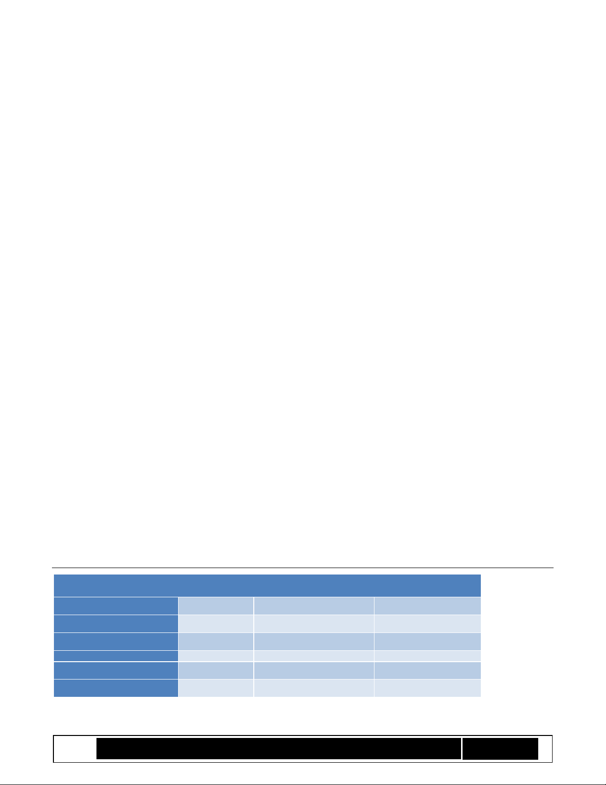
The following table provides you with some insight into the size that you need to reserve for the manifests.
Table 2 Typical Manifest Sizes
Manifest
Hash Alg
Signing Key Type/Size
Typical Manifest Size
KM w/1Key
SHA384
RSA 3072
869 (0x365) bytes
KM w/1Key
SHA256
RSA 2048
597 (0x255) bytes
KM w/1Key
SM3
SM2 (256)
213 (0x0D5) bytes
BPM w/8 IBB segments
SHA384
RSA 3072
1341 (0x53D) bytes
BPM w/8 IBB segments
SHA256
RSA 2048
1053 (0x41D) bytes
Page 9

Intel® TXT/BTG – BpmGen2 Tool User Guide
Technology Solutions Enabling Intel® TXT/BtG Tools
Page 9
BPM w/8 IBB segments
SM3
SM2 (256)
669 (0x29D) bytes
BPM sizing includes typical TXT Element, max PCD Element, and no PM Element.
In the future, the size of elements could increase and there could be additional elements.
A rule of thumb is to allocate at least 0x400 bytes for KM and 0x600 bytes for BPM
2.5 Using the Tool
2.5.1 Required Files
To use the tool, the following files from the toolkit need to be in your working directory:
BpmGen2.exe (the tool)
The following DLL files from the toolkit
o ippccp8-9.0.dll
o ippcore-9.0.dll
o ippcp-9.0.dll
o ippcpp8-9.0.dll
BIOS file to analyze (update)
BPM Parameter file
Public signing key (a PEM, DER, or binary file) – the private key file can be used
Private signing key (if using the tool to sign the BPM)
Batch file for signing (if externally signing the BPM)
Key Manifest binary file (optional)
2.5.2 Main Functions
The tools main functions are:
• BpmGen2 GEN : Generates a v1.0 or v2.0 BPM depending on the BPM Parameter file
• BpmGen2 KMGEN : Generates a v2.0 KM
• BpmGen2 KM1GEN : Generates a v 1.0 KM
• BpmGen2 INFO : Displays KM, BPM, or BIOS information
BKM: Issuing the command specifying only the main function without any additional parameters (i.e., BpmGen2
GEN ) displays the syntax for that function.
The following sections provide the syntax for invoking the tool. The tool is designed to be invoked from the DOS
prompt or as part of a batch file.
The main form for the syntax is:
ToolName OPERATION Required parameters Additional (optional) parameters
• All command line parameters are case insensitive (i.e., you can use upper and/or lower case characters).
• The syntax uses tags followed by zero or more variables (such as filename). Tags are shown in
UPPERCASE with “-“ as the first character (e.g., -TAG <filename>).
• Variables are shown encased in <…>.
• Optional parameters are indicated by brackets “[…]” and starts with a tag.
Page 10
Intel® TXT/BTG – BpmGen2 Tool User Guide
Technology Solutions Enabling Intel® TXT/BtG Tools
Page 10
2.5.3 Syntax for Displaying Boot Policy Information
BpmGen2 INFO <BiosFile>
-- displays the FIT, BPM, KM, and other information and calculates key hash
values
BpmGen2 INFO <KM or BPM filename>
-- displays the KM or BPM, and verifies its signature
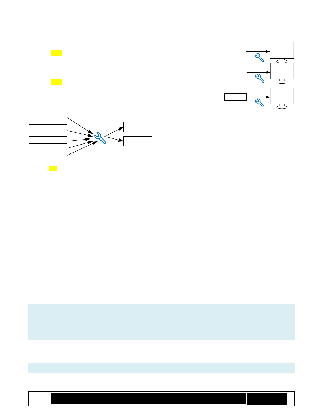
2.5.4 Syntax for Boot Policy Manifest Generation
Initial BIOS File
BPM
Parameters File
Key Manifest
User Data
Signing Key
Signed BPM
Modified
BIOS File
BpmGen2
Tool
BpmGen2 GEN <BIOSFileToUpdate> <BpmParamsFile> [-BPM <BpmOutputFileName>] [-U <UpdatedBIosFilename> [-KM <KeyManifiestFile>] ]
Either –BPM or –U (or both) must be specified
-BPM instructs the tool to save the BPM binary to the specified filename
-U directs the tool to update the BIOS file with the new BPM (and KM if specified) and then save
the updated BIOS image to the specified filename.
-KM instructs the tool to replace the KM in the updated BIOS image with the specified KM.
To use the –U option, the original BIOS file (BIOSFileToUpdate) must have a Firmware Interface Table (FIT) that
includes a Type 0x0c BPM record. This indicates where the tool will place the BPM. The size for this location
must be equal or greater that the size of the new BPM.
The –KM option can only be used with the –U option and the FIT must include a Type 0x0b KM record indicating
where the tool will replace the KM and the size specified for that location must be equal or greater that the size
of the specified KM.
Note that unlike the BPM, which must be updated for each BIOS build, the KM is typically only generated
once per project and thus you have the option of including it in the original BIOS file (BIOSFileToUpdate) or
having the tool insert it (-KM KeyManifiestFile) at the same time it updates the BIOS image with the new BPM.
To generate a modified BIOS with an updated BPM, you would use the following form:
BpmGen2 GEN <BIOSFileToUpdate> <BpmParamsFile> -U <UpdatedBIosFilename>
Which creates a new BPM based on the BIOSFileToUpdate plus BpmParamsFile and generates an updated BIOS
image with the new BPM saving it to UpdatedBIosFilename.
The BpmParamsFile contains static policy settings (i.e., the settings that typically don’t change from build to
build). See Chapter 3 “BPM PARAMS File” for details.
Example:
BpmGen2
Tool
Modified
BIOS File
FIT
BPM
KM
BpmGen2
Tool
BPM File
BPM
BpmGen2
Tool
KM File
KM
Page 11
Intel® TXT/BTG – BpmGen2 Tool User Guide
Technology Solutions Enabling Intel® TXT/BtG Tools
Page 11
BpmGen2 GEN BiosFile.Fd MyBpmParams.bpDef -U UpdatedBiosFile.Fd -KM MyKM.bin
Additional command line arguments include the following:
[-BLOCK [ <TsSize> ] ] : must be used with the –U option and instructs the tool to generate a BPM for a platform the
boots from a block device (in contrast to booting from a SPI flash device) and also prepends Boot Partition
Descriptor Tables to the BIOS image. TsSize is the Block Top Swap size. See Annex 6 “Boot from Block”.
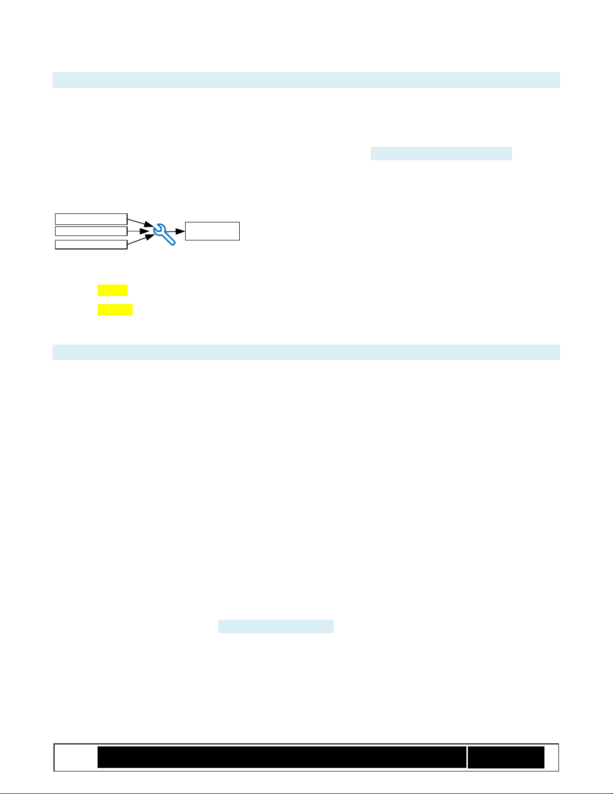
2.5.5 Syntax for Key Manifest Generation
BpmGen2
Tool
KM Parameters
Signing Key
Public Keys Signed KM
Note: using the BpmGen2GUI tool provides a more user-friendly way to generate a Key Manifest.
BpmGen2 KMGEN -KEY <BpKeyFileName> <keyParams> -KM <KmOutputFilename> [Optional settings] {Signing directive}
BpmGen2 KM1GEN -BPKEY <BpKeyFileName> -KM <KmOutputFilename> [Optional settings] {Signing directive}
Generates a signed KM where:
“KM1GEN” creates a v1.0 KM (for platforms prior to converged BGT/TXT) while “KMGEN” create a v2.1 KM.
Optional settings are not order dependent, Default value is used if not specified, and include:
–KMID <value 0-15> Default is 1
–SVN <value 0-15> Default is 1
–KMVERSION <value 0-255> Default is 1
–BPKHASH <SHA256 | SHA384 | SM3> (v1 only) hash alg used to create BPM Key Hash. Default is SHA256
–KMKHASH <SHA256 | SM3> (v2 only) hash alg used to create KM Key Hash. Default is SHA256
–SIGHASHALG <SHA256 | SHA384 | SM3> hash alg used in signing. Default is SHA256
–SIGALG <RSA | ECC> key algorithm. Default is RSA (use ECC for SM2 signing)
–SCHEME <RSASSA | RSAPSS | ECDSA | SM2> signing algorithm. Default is RSASSA
Signing directive must be one of the following:
–SIGNKEY <PrivateKeyFileName>] [–SIGNPUBKEY <KeyFileName>] Note: PubKey only needed when PrivateKey
does not contain the public key (most private key structures do).
–XSIGN <DataFile> <BatchFile> <sigFile> –SIGNPUBKEY <KeyFileName> [-OUTHASH] Tool will generate KM body and
save it to <datafile>, invoke <BatchFile> and then read the signature from <sigFile>. If you include
the -OUTHASH option, the tool will output the hash of the KM body instead of the KM body. Your
batch file is expected to take the <datafile>, and create <sigFile>, which is a binary signature the size
of the binary public key. See 4.4 “External Signing”.
[-KEY <BpKeyFileName><keyParams>] can be repeated to authenticate multiple keys (v2 only)
<KeyParams> can be any of the following:
[SHA256 | SHA384 | SM3] - Specifies the hash algorithm for creating the KeyHash (Default: SHA256)
[BPM] [FPM] [ACMM] [SDEV] [...] - Specifies Key usage (BPM, FIT Manifest, ACM Manifest, etc.) Default: BPM
Page 12

Intel® TXT/BTG – BpmGen2 Tool User Guide
Technology Solutions Enabling Intel® TXT/BtG Tools
Page 12
-U:<hexValue> - Specifies Key usage value (for setting usage bits not yet defined)
example: -U:83 would set BPM[0] FPM[1] and bit 7
BPM FPM -U:80 would also set BPM[0] FPM[1] and bit 7
The primary purpose of the KM is to authenticate the BPM public signing key. If you do have the need to
authenticate additional keys, the BPM key should be first.
A typical usage to have the tool sign the KM would be:
BpmGen2 KMGEN -KEY BpmPublic.pem BPM -KM MyKM.bin –SIGNKEY KmPrivate.pem
Or (for external signing):
BpmGen2 KMGEN -KEY BpmPublic.pem BPM -KM MyFirstKM.bin –XSIGN Data2Sign.SignIt.bat Signature.bin
3 BPM PARAMS File
An example BPM PARAMS file is provided in Appendix C. The BpmGen2GUI tool can be used to generate/edit
BPM PARAM files, but the BPM PARAM file is easily modified using a text editor. Let’s look at the various
sections of the BPM Params file and your options.
• Lines starting with # are section (and subsection) labels and must not be modified (nor moved).
• Don’t change the first 3 lines in the first section (# FILEHEADER).
• Lines starting with // are comments and are ignored by the BPMGen2 tool. You may insert or delete
comment lines, but comments cannot be added to the end of line i.e., “//” must be the first characters
of the line.
• The remaining lines use the format: TAG: Value – Don’t change the TAG.
• Some tags are used only by the BpmGen2GUI tool that generates the bpDef file and are ignored by the
BpmGen2 tool. Tags of interest are highlighted in Green font in this chapter.
• Some values (such as algorithm IDs) contain a numeric value (decimal or hex), followed by a “:” and then
text. The : and following text is ignored by the tool, but makes it easier for human interpretation. Thus,
just changing that text doesn’t change anything.
• The following subsections provide information on the values that you may modify.
3.1 BPM_DEF
Must be the first section following the FILEHEADER section. It starts with the “# BPM_DEF” label, and there must
be exactly one.
# BPM_DEF
PlatformRules: Server
BpmStrutVersion: 0x21
BpmRevision: 0x03
BpmRevocation: 0
AcmRevocation: 2
NEMPages: 0x20
IbbSetCount: 1
CurrentIbbSet: 0
Page 13

Intel® TXT/BTG – BpmGen2 Tool User Guide
Technology Solutions Enabling Intel® TXT/BtG Tools
Page 13
BpmStrutVersion: Typically 0x21 to build version 2 BPM. Setting this to 0x10 builds a v1.0 BPM.
BpmRevision: You specify an arbitrary value for BPM revision so you can identify different BPM builds. Max
values is 0xFF (255). Consider incrementing this value each time you modify the BpDef file or each time you
release a BIOS update.
BpmRevocation and AcmRevocation are used to revoke BPMs and ACMs respectively (aka anti-rollback).
BpmRevocation is the BPM’s SVN (Security Version Number) and AcmRevocation is compared to the ACM’s SVN.
Their values may be 0-15 (0x0 – 0xF). If for any reason you need to revoke a previous BPM, just increment
BpmRevocation and BPMs with lower SVN values will no longer be accepted once the platform boots using a valid
BIOS with the newer BPM. AcmRevocation is only effective if it matches the value of the ACM. Intel will inform
OEMs if an ACM ever needs to be revoked. ACMs with SVN of 0 or 1 are considered Non-Production-Worthy and
thus production Qualified ACMs will always have SVNs greater than 1. See Annex B.6 “Revoking Keys”.
Warning: Once BpmRevocation is incremented, its value is permanently saved on platforms that
boot with the new BPM and cannot be rolled back. Thus, there is a maximum of 15 BPM
revocations. So only revoke BPMs that pose a security concern.
NEMPages: BtG automatically allocates enough Non-Eviction Mode (NEM) memory in processor cache to hold
the IBB segments (both measured and Post IBB, however it only loads the measured segments). Here you can
specify the number of additional pages that IBB needs for data it also wants protected (such as its software
stack). Note that the total number of pages depends on the processor’s cache size and thus specifying too large
of a number could result in a failure. Client processors tend to have smaller cache sizes than server processors.
IbbSetCount and CurrentIbbSet are only used by the GUI tool that creates the BPM PARAMS file.
3.2 IBB SET
Section starts with the “# IBB_SET” label and in the future there might be multiple IBB_SET sections (e.g., one for
IBB Cold Boot Set and one for S3Resume Set). Currently, only the ColdBoot set can be included.
# IBB_SET
IbbSetType: 0:ColdBoot
IbbSetInclude: TRUE
PBETValue: 3
MCHBAR:
VTD_BAR:
//DMA Protection
DmaProtBase0:
DmaProtLimit0:
DmaProtBase1:
DmaProtLimit1:
IbbFlags: 0x3
// Bit0 : Enable DMA Protection
// Bit1 : Issue TPM Start-up from Locality 3
// Bit2 : Extend Authority Measurements into the Authority PCR
// Bit3 : On error: Leave TPM Hierarchies enabled. Cap all PCRs
// Bit4 : BIOS supports Top Swap
DmaProtAutoCalc: TRUE
Page 14

Intel® TXT/BTG – BpmGen2 Tool User Guide
Technology Solutions Enabling Intel® TXT/BtG Tools
Page 14
IbbHashAlgID: 0x0B:SHA256
IbbEntry: 0xFFFFFFF0
PostIbbHashAlgID: 0x10:NULL
PostIBBHashSource: Calculate
PostIbbHashFile: PostIbbDigest.hash
IbbSegSource: MANUAL
IbbSegBase: 0xFFA00000
IbbSegSize: 0x2C0000
IbbSegHashed: FALSE
IbbSegCacheType: WB
IbbSegFile:
IbbGuid: 4a4ca1c6-871c-45bb-8801-6910a7aa5807
ObbHashAlgID: 0x0B:SHA256
ObbHashSource: List
ObbHashFile: 32Byte.hash
ObbGuid: 9e21fd93-9c72-4c15-8c4b-e77f1db2d792: Example GUID
ObbGuid: 7bb28b99-61bb-11d5-9a5d-0090273fc14d: Example GUID 2//
# MINOR_VERSION_ADDITIONS: 1
IbbSetType: One of {0:ColdBoot, 1:S3Resume} Tool only looks at first character, which must be 0 or 1. Most
projects require a ColdBoot set and do not support other sets. Check the platform requirements.
IbbSetInclude: If FALSE, this set will be excluded from the BPM. Must be true for ColdBoot set. Must be FALSE for
any Set Type the target ACM does not support. BpmGen2 tool will ignore sets with IbbSetInclude == FALSE.
PBETValue: You specify the additional time (number of seconds) BIOS needs for the Protect BIOS Environment
Timer. Max value is 31. Actual timeout value will be 5s plus this value. PBET is started when the ACM invokes
the BIOS code at the specified entry point. If BIOS does not stop the PBET timer before it times out, the
platform will start the enforcement action for invalid BIOS.
See Chapter 4.7 “DMA Protection” for details on setting the following values.
MCHBAR: 64 bit value exactly as it is to be written to the MCHBAR
VTD_BAR: 64 bit value exactly as it is to be written to the VT-d BAR (not used on most server platforms)
Note MCHBAR and VTD_BAR ranges must exclude:
1 The flash range. [In HSW-ULT this is: 0xFFE00000 - 0xFFFFFFFF)
2 LT space [FED2_0000 thru FED3_FFFF]
3 Extended reserved/LT ranges [FED4_0000 thru FED7_FFFF]
4 The address space occupied by the ACM
BtG sets up DMA protection if you desire (IbbFlags.Bit0) using the following:
• DmaProtBase0 and DmaProtLimit0: 0x0 if not used
• DmaProtBase1 and DmaProtLimit1: 0x0 if not used
IbbFlags:
• Bit0 : Enable DMA protection (VT-d on client platforms and GenProt registers on server platforms)
• Bit1 : Issue TPM Start-up from Locality 3 – must be set for CBnT
• Bit2 : Extend Authority Measurements into the Authority PCR
Page 15

Intel® TXT/BTG – BpmGen2 Tool User Guide
Technology Solutions Enabling Intel® TXT/BtG Tools
Page 15
• Bit3 : On error: Leave TPM Hierarchies enabled. Cap all PCRs
• Bit4 : BIOS supports Top Swap for BIOS Update recovery
Note: Legacy BtG (1.0) allows you to select if DMA protection is enabled, but it is required for CBnT and thus the
BpmGen2 tool will force IbbFlags.Bit0 to be set. Same for IbbFlags.Bit1 – TPM Start-up from locality 3.
DmaProtAutoCalc: If TRUE, tool will calculate DmaProtBase0 and DmaProtLimit0 to cover all of the IBB segments
(IBB[0] to 4GB).
IbbHashAlgID: Algorithm the tool uses to calculate the measured IBB Segments. The tool only evaluates the
number portion of the Value. Tool supported values are 0x0B:SHA256, 0x0C:SHA384, 0x0D:SHA512, 0x12:SM3.
PostIbbHashAlgID: Algorithm used to calculate the Post IBB Segments. The tool only evaluates the number
portion of the value. Tool supported values are 0x0B:SHA256, 0x0C:SHA384, 0x0D:SHA512, 0x12:SM3,
0x10:NULL.
IbbEntry: Specify the BIOS entry point for when BtG verification is successful. See platform specs for limitations.
PostIBBHashSource: Specify either Calculate if tool is to calculate the PostIbbHash digest or File it the tool is to
read the digest from a file. Not used when PostIbbHashAlgID is 0x10:NULL. Selecting Calculate instructs the tool
to calculate the hash of the non-measured IBB segments. Note that if IbbSegSource == FIT, then there are no
non-measured IBB segments and either (a) PostIBBHashSource must be FILE (tool reads hash value) or (b)
PostIbbHashAlgID must be NULL (there is no PostIbbHash digest).
PostIbbHashFile: enter filename if PostIBBHashSource == File.
IbbSegSource: May be FIT, BIOS INFO, or MANUAL (see 4.6.3” Specifying the Source for IBB Segments)”.
IbbSegBase: Used for manual IBB specification. The base flash address of the IBB segment.
IbbSegSize: Used for manual IBB specification. The size of the IBB segment.
IbbSegHashed: Used for manual IBB specification. Whether the segment is included in the hash calculation (True)
or not (False).
IbbSegCacheType: Used for manual IBB specification. The cache type of the IBB segment. WB == Write Back, WP
== Write Protect.
IbbSegFile: for future use, no used.
IbbGuid: If IbbSegSource == BIOS INFO, then enter the GUID for the module that contains the BiosInfoTable.
The OBB Hash is not used by BtG ACM, but rather by IBB to validate the code after IBB. Thus the following
components are included in the BPM to provide IBB with authenticated values it can use to verify the remaining
BIOS validity. Thus the definition of OBB is up to the BIOS developer and platform architect. See Annex 7 “OBB
Hash” for more details. If BIOS does not use these components, then just set ObbHashAlgID = NULL.
ObbHashAlgID: Algorithm used to calculate the OBB hash digest. The tool only evaluates the number portion of
the value. Tool supported values are 0x0B:SHA256, 0x0C:SHA384, 0x0D:SHA512, 0x12:SM3, 0x10:NULL.
Page 16

Intel® TXT/BTG – BpmGen2 Tool User Guide
Technology Solutions Enabling Intel® TXT/BtG Tools
Page 16
ObbHashSource: Specify how the tool acquires the OBB Hash digest value. See Annex 7 “OBB Hash”. Not used
when ObbHashAlgID is 0x10:NULL. Selecting anything other than FILE instructs the tool to calculate the hash
from a section of the BIOS file. The tool accepts the following values:
• File : the tool is to read the digest from a file
• Base : Tool will calculate the hash from start of the BIOS image until the first IBB segment
• List : Tool will calculate the ObbHash digest using a list of UEFI Fv File GUIDs
• Start GUID : Tool will calculate the hash starting from the first byte of the Fv file indicated by the first
Obb GUID specified in this IBB section and ending at the first IBB segment.
ObbHashFile: enter filename if ObbHashSource == File.
ObbGuid: If ObbSegSource == LIST, then enter the GUID for an Fv File to include in the hash measurement. Repeat
this line for each file to be included. If ObbSegSource == START GUID, then enter the GUID for Fv File that marks
the start point. Only the first ObbGuid line will be used.
3.3 TXT ELEMENT
# TXT_ELEMENT
TxtInclude: TRUE
MinSvn: 0x01
TxtFlags: 0x00000000
// [4:0] = TXT execution profile
// 00000b – Use Default based on HW
// 00001b - Server Profile
// 00010b - Client Profile
// [6:5] = “Memory scrubbing” policy
// 00b - Trust Verified BIOS (default)
// 01b – Always trust BIOS to scrub
// 10b – Always use Backup Policy
// [7:8] = Backup policy
// 00b – Default
// 01b – Force power down memory depletion
// 10b – Force unbreakable shutdown
// [31] = Reset AUX control (1=AUX Reset leaf will delete AUX Index)
//MemoryDepletion Power Down:
AcpiBase: 0x400
PwrmBase: 0xFE000000
PdUseDefault: TRUE
PdMinutes: 5
PdSeconds: 0
PttCmosOffset0: 0x7E
PttCmosOffset1: 0x7F
//TXTE Segments
TxtSegSource: IBB
TxtSegGuid: 00000000-0000-0000-0000-000000000000
TxtSegHashAlgID: 0x10:NULL
//
This is an optional element
TxtInclude: Set to TRUE to include the TXT Element or FALSE to exclude it
Page 17

Intel® TXT/BTG – BpmGen2 Tool User Guide
Technology Solutions Enabling Intel® TXT/BtG Tools
Page 17
MinSvn: This value is used to restrict the minimum SINIT version allowed to run on the system.
TxtFlags: This is the value that the tool will place in TXT Flags and is composed of the following bits:
[4:0] = TXT execution profile – for server platforms this must be 00000b, for client platforms:
00000b – Use Default based on the platform’s HW
00001b – Unified (Server) Profile
00010b - Client Profile
[6:5] = Memory scrubbing policy for Surprise Reset – server platforms typically only support 00b
00b – Default – ACM allows BIOS to scrub memory only if IBB Cold Boot set verifies, else Backup policy
01b – ACM always allows BIOS to scrub memory
10b – ACM always resorts to Backup Policy to scrub memory
[7:8] = Backup policy – action to take to protect memory content when BIOS cannot scrub memory. Server
platforms typically only support 00b.
00b – Default (servers: Force unbreakable shutdown, client platforms: Force power-down interval)
01b – Force power down for specified interval (Power Down Memory Depletion)
10b – Force unbreakable shutdown
[31] = Reset AUX control
0 – When BIOS invokes GETSEC[ResetAux] the ACM will reset the AUX index.
1 – When BIOS invokes GETSEC[ResetAux] the ACM will delete the AUX Index – Should only be set for a
BIOS used during platform refurbishing and MUST never be set for a BIOS that will be shipped to
customers.
The following elements establish Power Down Memory Depletion parameters (see section 5 “Power Down
Memory Depletion”).
AcpiBase: Value the ACM needs to program into PCI configuration register BAR2 of device Bus 0 : Device 31 :
Function 2 : Register 0x20 to map fixed ACPI IO registers into IO bus. Default is 0x400.
PwrmBase: Value ACM will program into PCI configuration register PWRMBASE of device Bus 0 : Device 31 :
Function 2 : Register 0x10 to map fixed ACPI MMIO registers into memory bus. Default is 0xFE000000.
PdUseDefault: Set to TRUE to use the ACM’s default power down duration. Set to FALSE to use the value
specified by PdMinutes and PdSeconds, which specify the minimum time to power down the platform to ensure
memory content is lost.
PttCmosOffset0: Location of a byte in CMOS memory the ACM can use (must be unused and in bank 0, i.e., 0-127)
PttCmosOffset1: Location of another byte in CMOS memory the ACM can use.
These 2 locations are only used if platform uses PTT and supports Power Down Memory Depletion.
TXT Segments provides the ACM with a list of all BIOS segments that are executed when BIOS has to scrub
memory. Currently, most platforms require BIOS memory scrubbing code be part of the measured IBB Cold Boot
set and thus ACM will use the IBB Cold boot set.
Page 18

Intel® TXT/BTG – BpmGen2 Tool User Guide
Technology Solutions Enabling Intel® TXT/BtG Tools
Page 18
TxtSegSource: Choice of {IBB, FIT, or BIOS INFO}. The value IBB tells ACM to use the IBB Cold Boot set as
defined in the IBB element, otherwise the tool generates segments from the FIT or from a BIOS Info Table (see
4.6.3” Specifying the Source for IBB Segments)”. Most platforms require a value of IBB.
TxtSegGuid: if TxtSegSource == BIOS INFO, then enter the GUID for the module with the BiosInfoTable
TxtSegHashAlgID: Must be 0x10:NULL if TxtSegSource == IBB. Otherwise must be one of {0x0B:SHA256,
0x0C:SHA384, 0x0D:SHA512, 0x12:SM3} and the tool will generate the list of TXT segments and calculate their
hash.
3.4 PLATFORM_CONFIG_ELEMENT
This element provides the ACM with the information about the platform. Specifically for specifying a location
that BIOS can use to request the ACM perform Power Down Memory Depletion. See section 5.2 “On Demand
Power Down Memory Depletion”. This location must be non-volatile so the architecture allows you to specify
either a CMOS location (must be in the first CMOST bank so it is accessible at power on) or you can use a TPM
NV Index. Since platforms might have a different family of TPM, you can specify up to 3 NV Indexes (one for
TPM1.2, 2.0, and PTT).
# PLATFORM_CONFIG_ELEMENT
PdReqLocation: TPM
// Power down request location for CMOS
CmosIndexRegister: 0x70
CmosDataRegister: 0x71
CmosIndexOffset: 125
CmosBitFieldWidth: 3
CmosBitFieldPosition: 0
// Additional binary to be measured by the ACM
PcdDataFile: Data.bin
// Power down request location for TPM1.2
# TPM1.2_LOCATION
TpmIndexHandle: 0x50000004
TpmByteOffset: 7
TpmBitFieldWidth: 3
TpmBitFieldPosition: 0
// Power down request location for TPM2.0
# TPM2.0_LOCATION
TpmIndexHandle: 0x01C10104
TpmByteOffset: 7
TpmBitFieldWidth: 3
TpmBitFieldPosition: 0
// Power down request location for PTT
# PTT_LOCATION
TpmIndexHandle: 0x01C10104
TpmByteOffset: 7
TpmBitFieldWidth: 3
TpmBitFieldPosition: 0
//
PdReqLocation: Choices are {TPM, CMOS}, informs the ACM whether the BIOS will use CMOS or the TPM as a
mailbox where BIOS can request that the ACM perform the Power Down Memory Depletion sequence.
Page 19

Intel® TXT/BTG – BpmGen2 Tool User Guide
Technology Solutions Enabling Intel® TXT/BtG Tools
Page 19
The following identifies the Power Down Request location in CMOS – must be present if PdReqLocation == CMOS,
otherwise they are not used if present.
CmosIndexRegister: Address of IO register to write the CMOS Index offset (CmosIndexOffset)
CmosDataRegister: Address of IO register to read/write the CMOS data at the CMOS index offset
CmosIndexOffset: Value to write to CmosIndexRegister (must be in bank 0)
CmosBitFieldWidth: number of bits - MUST be at least 3 and should be 3
CmosBitFieldPosition: bit offset within the CmosDataRegister that contains the BIOS request
The following identifies the additional data to be measured by the ACM. This is typically a binary structure that
will be consumed by the BIOS.
PcdDataFile: Additional data to be measured within the PCD Element.
The following identify the Power Down Request location in a TPM NV Index – Can be up to 3 (one for TPM1.2,
one for TPM2.0, and one of PTT) - at least one set must be present if PdReqLocation == TPM, otherwise (for
PdReqLocation == CMOS) they are not used if present.
Each subsection is preceded by a marker line indicating the type of TPM ( # TPM1.2_LOCATION, #
TPM2.0_LOCATION, # PTT_LOCATION). If the platform will never have a particular type of TPM (such as PTT),
then you may remove that subsection, or just set the value of TpmIndexHandle to 0, or just use the same
values you set for TPM2.0.
TpmIndexHandle: the NV Index handle – ACM must be able to read and write using empty authValue
TpmByteOffset: The byte offset of the NV Data
TpmBitFieldWidth: The width of the request in bits (must be at least 3 and should be 3)
TpmBitFieldPosition: The bit offset of the request location starting at the TpmByteOffset.
3.5 PLATFORM_MANUFACTURERS_ELEMENT
# PLATFORM_MANUFACTURERS_ELEMENT
PmdeInclude: FALSE
PmdeFile:
//
The PM Element is optional and provides a means for you to provide whatever information you need to BIOS, if
any, that needs to be protected by the BPM signature.
PmdeInclude: Set to FALSE to exclude this element and set to TRUE to include it.
PmdeFile: If PmdeInclude == TRUE, then the content of this file will be placed in the BPM (but ignored by the
ACM). This must be a file that is available to the BpmGen2 tool when it is executed. File size must be an integer
number of DWORDs.
Page 20

Intel® TXT/BTG – BpmGen2 Tool User Guide
Technology Solutions Enabling Intel® TXT/BtG Tools
Page 20
3.6 BPM_SIGNATURE
# BPM_SIGNATURE
BpmSigSource: Internal
BpmSigHashAlgID: 0x0B:SHA256
BpmSigKeyType: 0x01:RSA
BpmSigScheme: 0x14:RSASSA
BpmKeySizeBits: 2048
BpmSigPubKey: SamplePublicKeyRsa2048.pem
BpmSigPrivKey: SamplePrivateKeyRsa2048.pem
BpmSigBatch: ExampleExternalSigning.bat
BpmSigData: Bpm2Sign.bin
BpmSigDataType: BPM Body
BpmSigXSig: X-SignedBpmSig.bin
//
BpmSigSource: Choice of {Internal, External} – informs the tool whether it will sign the BPM or it will call your
batch file for signing it.
BpmSigHashAlgID: Choice of {0x0B:SHA256, 0x0C:SHA384, 0x0D:SHA512, 0x12:SM3} – the hash algorithm for
signing. SHA512 not currently supported by any platform.
BpmSigKeyType: Choice of {0x01:RSA, 0x23:ECC} – use ECC for SM2 signing.
BpmSigScheme: Choice of {0x14:RSASSA, 0x16:RSAPSS, 0x18:ECDSA, 0x1B:SM2} – ECDSA not currently supported
by any platform. Check with your platforms specification for which signing schemes are supported.
BpmKeySizeBits: Specify key size (2048 or 3072 for RSA keys otherwise 256 or 384 for ECC/SM2 keys)
BpmSigPubKey: Specify the Public Key file (typically a PEM file, may be DER or binary). File does not need to be
specified if internal signing and private key file also contains the public key.
BpmSigPrivKey: Specify the Public Key file (typically a PEM file, may be DER or binary). File only needs to be
specified when BpmSigSource == Internal.
BpmSigBatch: Specify the batch file the tool will invoke if BpmSigSource == External.
BpmSigData: Specify the name of the file the tool creates (for BPM body to be signed or Hash of Bpm body to be
signed) when BpmSigSource == External.
BpmSigDataType: Specify if tool writes BPM body or hash of BPM body to BpmSigData file when BpmSigSource ==
External. Default is BPM Body.
BpmSigXSig: Specify the name of the file the tool reads to get the signature when BpmSigSource == External.
4 Understanding Your Role and Responsibilities
Editorial Note: I have been developing tools for Intel TXT, Intel BtG, TPM, and other security technologies for
many years and realize that trying to understand what you need just by reading the technology specs, platform
specs, and BIOS specs can be challenging. So I put together this guide to help you better understand what you
need to do and the options you have. In the context of honesty, I am not a BIOS developer, so I cannot provide
Page 21

Intel® TXT/BTG – BpmGen2 Tool User Guide
Technology Solutions Enabling Intel® TXT/BtG Tools
Page 21
you all the details. Also, my primary focus (and thus expertise) has been on server platforms. However, I do
work with architects for client platform technologies to produce tools (like this BpmGen2 tool) that works for
both client and server platforms. Disclaimer, this document only focuses on creating the manifests and is by no
means a complete guide on either BtG or TXT. Furthermore, I tend to simplify. So for any discrepancy between
this document and the specifications (like Bios Writer’s Guides), those specifications should take precedence.
Lastly, security technologies advance at an aggressive pace and so this document might not cover the latest
developments, especially concerning what is or is not supported by client and server platforms.
In this guide, the term OEM refers to a combination of the platform architect, the BIOS developer, and
manufacturing engineer. Each of these has a role in producing an Intel® Boot Guard compliant platform. The
assumption is that the platform architect is responsible for overall direction, as well as creating the Key Manifest
while the BIOS developer implements that direction and is responsible for producing the Boot Policy Manifest. If
you are reading this document, I assume you are either the architect or the BIOS developer, so when I say OEM,
I most likely mean you, your peers, or your management.
Note that some details are omitted or generalized for clarity.
4.1 A note about BtG Profiles.
Part of the platform manufacturing process requires blowing Field Programmable Fuses (FPFs) that determine
the platform’s support for Intel BtG and Intel TXT. A subset of those FPFs is known as immutable Boot Policy
where the OEM specifies BtG operation by setting F, V, M, and ENF. The combinations of these that are
considered valid are known as BtG Profiles and there were Profiles 0 thru 5. Profiles #1 & #2 fell by the roadside
and #3 is only for pre-production testing. Now, with the convergence with Intel TXT, there is another designator
“T” added. So current profiles are 0, 0T, 3, 3T, 4, 4T, 5, 5T.
Here is an unofficial interpretation of the various profiles:
0
F=V=ENF=M=T=0: BIOS does not support either Intel BtG or Intel TXT (no KM or BPM required) –
Platform does not do any BtG enforcement – startup ACM is not invoked, BIOS starts executing at the
Reset Vector. For all other profiles, start-up ACM will execute before BIOS executes.
0T
F=V=ENF=M=0; T=1: BIOS only supports Intel TXT, no BtG enforcement, but KM and BPM needed. –
Server platforms might not support this profile because Server TXT depends on BtG protections. BIOS
starts executing at the Reset Vector. BIOS measures IBB into PCR0.
3
F=0; V=M=1; ENF=1: Same as #5 (or #5T) except without strict enforcement (i.e., platforms continues to
boot if IBB validation fails) allowing tools and other debugging efforts to execute. Used only for debug
and not for production. If IBB verification fails, BIOS starts executing at the Reset Vector, otherwise starts
at IBB Entry Point specified in Boot Policy Manifest.
3T
4
F=V=1; ENF=3; M=T=0: BtG support only - for platforms that do not have a TPM or where BIOS extends
IBB measurements into PCR0 - platform enters unbreakable shutdown if IBB verification fails. Otherwise
starts BIOS starts executing at IBB Entry Point specified in Boot Policy Manifest.
Page 22

Intel® TXT/BTG – BpmGen2 Tool User Guide
Technology Solutions Enabling Intel® TXT/BtG Tools
Page 22
4T
F=V=T=1; ENF=3; M=0: BtG & TXT supported - platform enters unbreakable shutdown if BtG verification
fails. Otherwise starts BIOS starts executing at IBB Entry Point specified in Boot Policy Manifest. BIOS
extends IBB measurements into PCR0.
5
F=V=ENF=M=T=0: BtG support only - for platforms with a TPM. Platform enters unbreakable shutdown if
BtG verification fails. Otherwise starts BIOS starts executing at IBB Entry Point specified in Boot Policy
Manifest.
5T
F=V=ENF=M=T=0: BtG and TXT - platform enters unbreakable shutdown if BtG verification fails.
Otherwise starts BIOS starts executing at IBB Entry Point specified in Boot Policy Manifest.
Typical profiles for client platforms are 0, 0T, 4, 4T, 5, 5T and for server platforms 0, 4, 5, 5T. The difference is
because historically client BIOS has always extended IBB measurements into PCR0, but server platforms relied
on the start-up ACM to make those measurements and extend them into the TPM.
4.2 Intel Boot Guard Overview
One of the primary purposes of Intel® Boot Guard (Intel BtG) is to verify that the BIOS code is what the OEM
provided and has not been inadvertently or maliciously altered. To do this, an ACM provided by Intel executes
before BIOS is allowed to execute. The ACM verifies the initial BIOS code and sets up protections to prevent
attacks against that code. The BtG ACM needs to know what code to measure and its expected measurement.
Thus the Boot Policy Manifest (BPM), created by and signed by the OEM, tells the ACM what to measure and
what to protect.
Let’s define some terms:
• Initial Boot Block (IBB) – BIOS code that executes before memory initialization and needs to be
protected by the ACM
• Measured IBB – the portion of the IBB that the ACM will measure and verify
• Post IBB – the rest of the IBB that the measured IBB will measure and verify
• Other Boot Block (OBB) (aka OEM Boot Block) – BIOS code that executes after memory initialization
(verification and protection established by IBB)
The BPM provides a list of IBB segments, where each segment has a flag telling the ACM if that segment is to be
included in the verification measurement.
The ACM:
• Authenticates the Key Manifest (verifies KM structure and signature)
• Authenticates the BPM (verifies BPM structure and signature)
• Allocates processor cache as Non-Evict Memory (NEM) to cover all IBB
• Loads the Measured IBB segments into the NEM
• Verifies that that the measurement of the measured segments match the hash digest in the BPM
• If any of the authentication or verification steps fail, enter an unbreakable shutdown state
• If Boot Policy M-bit is set, starts TPM and extends IBB measurement into PCRs
• Sets up DMA protection (as per the BPM)
Page 23

Intel® TXT/BTG – BpmGen2 Tool User Guide
Technology Solutions Enabling Intel® TXT/BtG Tools
Page 23
Once the measured IBB code is verified, it is allowed to execute and is expected to continue the chain of trust by
measuring and verifying the rest of the code as follows:
• Load the PostIBB segments into NEM
• Verifies that that the measurement of the Post IBB segments match the PostIBB hash digest in the BPM
• Initializes memory
• Sets up protections (reconfigure DMA protection to cover IBB and OBB, etc.)
• Verifies that that the measurement of the OBB code matches the OBB hash digest in the BPM
Determining which BIOS modules constitute IBB and OBB is the BIOS developer’s responsibility. The ACM does
nothing with the PostIbbHash nor the ObbHash values in the BPM, so their use is also left to BIOS developer.
Note that the IBB will need additional NEM to function as a stack. The “NEMPages” in the BPM Header tells the
ACM how many additional pages of NEM the IBB needs. A typical value of 32 (0x20) provides for 128KB.
4.3 Manifests
The purpose of the Key Manifest is to authenticate OEM keys, in particular the key that the OEM authorizes to
sign the BPM. For authentication of the Key Manifest signature, the manufacturing process programs the hash
digest of the public key portion of the KM signing key into the chipset’s Field Programmable Fuses (FPF’s). Intel
BtG will verify that the public key in the KM signature block is in fact the public key specified by the FPF’s. And
then it will validate the KM signature using that public key.
One of the components in the KM is the hash of the BPM’s public signing key. Intel BtG will then verify that the
public key in the BPM signature block is in fact the public key specified in the KM. And then it will validate the
BPM signature using that public key.
The OEM must create a Key Manifest, signed with the key provisioned into the FPFs that authorizes the key that
will be used to sign the BPM.
See B.2 “Master and Subordinate Keys” for suggestions on using different keys for different platforms.
See B.3 “Development vs. Production” for some recommendations on how to use different key manifests during
the debug and validation process.
4.4 External Signing
While you might want to let the tool do the signing during development, the signing keys for production
platforms must be kept very secure. So you have the option to use your own signing service to sign the BPM.
You select internal or external signing via the BPM Params file (BpmSigSource).
When BpmSigSource == External, the tool builds the BPM body, writes it to the file specified by BpmSigData, and
then invokes the batch file specified by BpmSigData. Your batch file must sign BpmSigData and create a signature
file (BpmSigXSig) which has the following format:
• For RSASSA signatures, a binary file containing a key size signature (i.e., signature[KeySize]). This is
typical of an OpenSSL generated RSA signature.
• For ECC (including SM2) either:
1 a binary file that contains a DER structure of Sequence { Integer R, Integer S}
Page 24

Intel® TXT/BTG – BpmGen2 Tool User Guide
Technology Solutions Enabling Intel® TXT/BtG Tools
Page 24
2 a Binary file with R[keySize], S[KeySize] (i.e., the file length is exactly 2 * KeySize)
R and S must be in Big Endian order, which is typical for OpenSSL and other standard signing utilities.
#1 is typical for an OpenSSL ECC signature.
For example, we used the following OpenSSL command in a batch file to generate an external signature:
openssl dgst -SHA256 -sign SamplePrivateKeyRSA2048.pem -binary -out X-sig.bin Data2Sign.bin
Also, if you prefer the tool to output the digest of the BPM Body rather than the Bpm Body, you can set
BpmSigDataType to HASH.
The same external signing concept applies to creating the Key Manifest (except signing directives are specified
on the command line instead of the BPM Params file.
4.5 BPM
The OEM must create a Boot Policy Manifest, signed with the key specified in the KM.
The BPM consists of a header plus two or more elements:
• IBB Set Element – required. Specifies required information for Intel BtG.
• TXT Element – option element that specifies polices for Intel TXT.
• Platform Configuration Data Element – optional element that specifies information the Power Down
Memory Depletion process.
• Platform Manufacture’s Element – optional element that allows you to provide additional information in
the BPM. Such as information the IBB needs to validate the OBB.
• Signature Element.
The Entry point specified in the BPM IBB Set Element must be inside one of the IBB Measured Segments.
The IBB Set Element must contain at least one measured segment.
4.6 Specifying IBB Segments
For each IBB set, the tool creates a list of IBB segments and calculates their composite hash measurement.
4.6.1 IBB Sets
Currently, ACM’s only support a single set of IBB definitions, but you might notice implications of multiple Sets.
This is an advanced topic and if you are curious, here is more information.
The BtG architecture allows for different sets of IBB depending on the state of the platform. For instance, the set
of code that executes on a cold boot could be different than the code that executes after an S3 resume. Current
platforms only support a single IBB Cold Boot Set. So you can ignore references to additional sets for now and
just concentrate on the Cold Boot Set.
For future compatibility the BpmGen2 tool is designed to handle multiple IBB sets, and it is anticipated that
additional sets, if/when supported, will be optional. Once multiple sets are supported, you will be able to select
Page 25

Intel® TXT/BTG – BpmGen2 Tool User Guide
Technology Solutions Enabling Intel® TXT/BtG Tools
Page 25
which sets will be included in the BPM via the BPM PARAM’s file. The configuration of each set is the same as for
the Cold Boot Set.
4.6.2 Tradeoffs
You need to specify which BIOS modules are part of the IBB (as measured and as post IBB segments). Refer to
[2]“Intel® BTG/TXT Server Design Guide” for a discussion on what modules should be included.
There is no hard fast definition of what needs to be a measured IBB segment or a PostIbb segment. Also, there is
no requirement that there be any Post IBB segments. It is up to you. You make that tradeoff and should consider
boot latency and ease of implementation. An easy route might be to include all pre-memory code as measured
IBB segments and therefore have no PostIBB segments. This is a good way to start. Let’s refer to this as OptionA. Later you might change to a more responsive model with PostIbb segments. Some considerations are:
• ACM execution occurs before any platform initialization. Processor and I/O are operating default (low)
speeds. So minimizing the amount of code that the ACM has to measure will reduce the ACM latency.
Thus you might want to defer measurement of part of the IBB until after the measured IBB code
initializes certain components that will improve performance and efficiency.
• Reducing the size of the measured IBB code also reduces risk of BtG verification failure. The smaller the
footprint, the less exposure. Just make sure that the measured IBB code can handle verifying the PostIbb
code. Remember, if measured IBB code verification by ACM fails, it results in an unbreakable platform
shutdown with no chance for BIOS to execute. On the other hand, verification failure of PostIbb code
(done by the measured IBB) allows the measured IBB code to take corrective action.
4.6.3 Specifying the Source for IBB Segments
You have several options.
The tool can derive IBB segments automatically from BIOS using one of two methods, or the tool provides a third
option for you to manually specify the IBB segments:
• Manual IBB Specification – In order to differentiate segments to be included/excluded in the IBB hash
calculation, manual IBB specification must be used. In manual mode, you can specify the base flash
address of an IBB segment, the segment’s size, whether the segment is hashed or non-hashed, and
whether the cache type is Write Back or Write Protect.
• FIT Table Type 7 Records – When using this method, the IBB set consists of measured segments being
the set specified by FIT Type 7 records and there will be no Post IBB segments. This mandates Option-A.
Note: FIT Type 7 records were used by previous TXT implementations on server platforms to specify the
Start-up BIOS code that would be validated to trust BIOS to scrub memory.
• BIOS Info Table – this is the same table that the FitGen tool uses to generate the FIT. The BIOS
developer needs to set the attribute fields in that table as follows:
BIOS Info Table provides a list of modules, module type, and modules attributes. We are only interested in
Module Type == FIT_TABLE_TYPE_BIOS_MODULE. Module attributes are defined as follows:
• Bits 0-3 are general and apply to all record types
o Bit 0 is defined as “Exclude from FIT”
o Bit 1-3 reserved
Page 26

Intel® TXT/BTG – BpmGen2 Tool User Guide
Technology Solutions Enabling Intel® TXT/BtG Tools
Page 26
• Bits 4-7 are Type specific. For BIOS Module type they are interpreted as follows:
o Bit 4: Include as a “Post IBB” segment
o Bit 5: Exclude from ColdBoot Set
o Bit 6: Exclude from S3-Resume Set
o Bit 7: (reserved for future)
So, for IBB Cold Boot Set, using BIOS Info Table, set attributes to 0x00 for Measured IBB segments, and to 0x10
for PostIbb segments. Setting will be slightly different for other set types.
Bit 4
Bit 5
Bit 6
Include in
Cold Boot Set
Include in
S3 Resume Set
0 0 0
As Measured
As Measured
1 0 0
As non-measured
As non-measured
0 1 0 x As Measured
1 1 0 x As non-measured
0 0 1
As Measured
x
1 0 1
As non-measured
x
x 1 1
x
x
FYI:
• Attributes ==0 equates to the module being included in the FIT and in all sets as a measured segment
• The PostIBB bit determines if the module will be included as a measured or a Post IBB segment
• Setting either ExcludeFromFIT or PostIBB results in the module being excluded from the FIT (using the
FitGen tool).
• Setting ExcludeFromCB and/or ExcludeFromS3 bits excludes the module from being included in that
respective set.
Also note: For legacy TXT, the BIOS ACM and portions of the FIT were required to be covered by FIT Type 7
records. For Converged Intel BTG/TXT, they need to be excluded from the IBB set. Thus, those modules should
have the ExcludeFromCB (and ExcludeFromS3) bit set. But don’t worry, if they are included, the BpmGen2 tool
detects IBB segments that cover those components and will modify the segments to exclude those areas, even if
it has to split a segment into two or more segments.
4.7 DMA Protection
You can instruct the startup ACM to setup DMA protection for the BIOS. This is required for CBnT.
This is one area where Client platforms (including some entry level servers and low end workstations) differ
slightly from Server platforms (including high end desktops and workstations that use server processors).
4.7.1 Client Model:
Platforms based on client processors and chipset use the VT-d engine to protect the BIOS. To have the ACM
setup DMA protection you need to do the following:
• Set the Enable DMA Protection bit in IBB Set: Flags
Page 27

Intel® TXT/BTG – BpmGen2 Tool User Guide
Technology Solutions Enabling Intel® TXT/BtG Tools
Page 27
• Specify the IBB Set: MCHBAR and VTD_BAR addresses that the ACM is to program the exclusion
registers.
• Specify the address range to be protected in IBB Set: DmaProtBase0 and DmaProtLimit0
• If desired, specify a second address range to be protected in DmaProtBase1 and DmaProtLimit1,
otherwise set them to 0 if not used. Some ACMs might not support the second range.
if you do not desire the ACM to set up DMA protection then clear the Enable DMA Protection bit in IBB Set:
Flags and set all base/limit values to 0. This is only valid for older platforms using BPM version 1.0.
4.7.2 Server Model:
Server platforms (which support multi-socket configurations and thus have multiple DMA engines) instead use
General Protection (GenProt) Registers. To have the ACM setup DMA protection you need to do the following:
• Set the Enable DMA Protection bit in IBB Set: Flags
• Specify the address range to be protected in IBB Set: DmaProtBase0 and DmaProtLimit0
• If desired, specify a second address range to be protected in DmaProtBase1 and DmaProtLimit1,
otherwise set both to 0 if not needed.
If you desire not to have the ACM to set up DMA protection then set all base/limit values to 0. This is only valid
for older platforms using BPM version 1.0.
5 Power Down Memory Depletion (PDMD)
Memory scrubbing is an Intel TXT feature which provides mitigation against reset attacks. A reset attack is when
an agent forces a platform reset before the OS has had a chance to scrub its secrets from memory in hopes of
gaining access to those secrets.
Historically, Client platforms differ from Server platforms in how memory gets scrubbed but with converged
BtG/TXT, the client model is converging with server model (where the ACM needs to rely on BIOS to scrub the
memory). But BIOS (IBB) must be trusted to do that. But what happens if IBB verification fails? There are two
backup methods that the ACM can fall back on. One is to enter an unbreakable shutdown and another is to turn
off the platform power long enough for memory content to be depleted.
Currently, servers don’t support the Power Down Memory Depletion method (because Server TXT requires Btg
Profile 4 or 5, which mandate unbreakable shutdown if BIOS integrity verification fails).
On client platforms, the ACM is capable of turning off the platform for a specified amount of time to assure
there are no secrets remaining in memory after a surprise reset or when requested by BIOS (e.g., BIOS memory
scrubbing fails).
The OEM provides information via the BPM that the ACM needs since the ACM executes before BIOS. The ACM
must be able to:
• Read the current time from the Real Time Clock (RTC)
• Determine if there was an RTC power failure (access to PWRM)
• Program the RTC Alarm
Page 28

Intel® TXT/BTG – BpmGen2 Tool User Guide
Technology Solutions Enabling Intel® TXT/BtG Tools
Page 28
• Put the platform into S5 state (for this you need to specify TXT_ELEMENT.AcpiBase and
TXT_ELEMENT.PwrmBase).
• Persistently store a “Ref Time” value so ACM can determine if the platform powered off long enough
If the platform supports PTT, there needs to be two bytes in the RTC CMOS memory that the ACM can use. You
specify which bytes via TXT_ELEMENT.PttCmosOffset0 and TXT_ELEMENT.PttCmosOffset1. They do not need to be
contiguous, but must be in bank 0 since other banks might not be accessible after platform reset.
You control the length of time the platform must remain off. If you set TXT_ELEMENT.PdUseDefault to TRUE, then
the ACM will use a time that Intel has determined is sufficient for all memory types (approximately 10 minutes).
Newer memory tends to deplete much faster, so if you know what the depletion time is for the memory that
you support, then you can set TXT_ELEMENT.PdUseDefault to FALSE and set the time via TXT_ELEMENT.PdMinutes
and TXT_ELEMENT.PdSeconds. This could significantly reduce the time the platform is unavailable after a surprise
reset. The combination of minutes plus seconds is used (up to the maximum limit), for example 5 minutes 30
seconds is the same as 0 minutes 330 seconds.
5.1 Invoking PDMS after a Surprise Reset
The BPM TXT Element contains several policy settings that impact the memory scrubbing process.
TXT_ELEMENT.Flags.BackupPolicy specifies which backup method the ACM invokes when Backup action is needed:
00b – Default – Servers use unbreakable shutdown and clients use Power Down Memory Depletion
01b – Use Power Down Memory Depletion
10b – Use unbreakable shutdown
TXT_ELEMENT.Flags.MemoryScrubbingPolicy controls when the ACM invokes the Backup method after a surprise
reset (which is considered a potential Reset Attack).
00b – if BIOS IBB integrity (as per ColdBoot set) does not verify, then the ACM will use the “Backup”
method. If it does verify, the ACM lets the BIOS scrub memory.
01b – ACM doesn’t use the “Backup” method (unless requested by BIOS). The ACM will always trust the
BIOS to scrub the memory. Use this setting if your platform lacks the resources to support Power
Down Memory Depletion.
10b – The ACM always uses the “Backup” method to scrub memory after a surprise reset. Thus BIOS will
never be invoked until after the sequence completes and the ACM has cleared the Secrets flag.
5.2 On Demand Power Down Memory Depletion
Client ACMs allow the BIOS to request the Power Down Memory Depletion process. This requires a non-volatile
location (3 bits) that the ACM can read and write. The BIOS writes to this location to request the process and
then resets the platform. On each reset, the ACM inspects that location and, if BIOS had set a PD request value,
the ACM invokes the process. When the process completes, the ACM resets the request by clearing those 3 bits.
Refer to the BIOS spec for the value the BIOS writes to invoke the process.
For this request location, the BIOS may use bit in RTC CMOS or in a TPM NV Index. The
PLATFORM_CONFIG_ELEMENT provides the information the ACM needs to access the PD Request Location. Note
that when using a TPM NV Index, the Index data must be able to be read and written by both BIOS and by the
Page 29

Intel® TXT/BTG – BpmGen2 Tool User Guide
Technology Solutions Enabling Intel® TXT/BtG Tools
Page 29
ACM. Thus the index attributes must allow anyone to read/write. The SGX index satisfies this requirement, but
you may use any NV Index that meets the access requirements.
6 Boot from Block
Some devices, such as cell phones and tablets don’t have a BIOS flash device mapped into processor memory
space, but rather use a block media device that contains the BIOS image that gets loaded into the processor
memory. These platforms have additional requirements and require that the BPM be built to meet those
requirements.
The BpmGen2 tool allows you to build an initial BIOS image that could be used for both block and non-block
boot.
Some of the requirements are:
• For non-block boot mode:
o Do not specify –BLOCK on the BpnGen2 command line
o IBB Entry point must be in an IBB segment above 4GB-64KB and is entered in real mode. That
code transitions the processor into protected mode.
o Thus at least one IBB segment must be above 4GB-64KB.
o Entry point is specified by a line in the BPM Params file.
• For block boot mode:
o Specify –BLOCK on the BpnGen2 command line (and optionally a Top Swap size).
o IBB segments must be contiguous (or have very little space between them)
o IBB segments must be located below 4GB-256KB
o Thus IBB Entry point for block boot mode must be in a segment located below 4GB-256KB and
that entry point is invoked from protected mode (i.e., ACM transitions processor into protected
mode).
o Entry point is located by a GUID:
0x50626249, 0x456D, 0x746E, 0x72, 0x79, 0x50, 0x6F, 0x69, 0x6E, 0x74, 0x00
o BpmGen2 tool prepends Boot Partition Descriptor Tables to beginning of the modified BIOS file
that the tool generates.
o Top Swap works differently for Block than it does when booting from SPI Flash devices.
• Flash Remap
o For certain client platforms it may be necessary to adjust the flash base address (typically
0xFFFF0000). In order to do this, the user must pass the -REMAP parameter, specifying an
adjusted flash base. Example offset of 256K: -REMAP 0xFFFC0000.
For non-block boot, Top Swap region is typically between 128KB and 1MB. For Block Boot mod, the Top Swap
size must cover the all of the critical code, which includes the FIT, ACM, FIT patches, KM, BPM, and IBB. Since a
typical IBB is currently about 3MB, Top Swap size is much larger and the BIOS update process is different.
By specifying the –BLOCK parameter on the command line, the BpmGen2 tool builds a BPM for booting from a
block device.
Page 30

Intel® TXT/BTG – BpmGen2 Tool User Guide
Technology Solutions Enabling Intel® TXT/BtG Tools
Page 30
Figure 2 BPM Processing with -BLOCK option
When building the BPM without the –BLOCK directive, the tool lists all IBB segments in the BPM. However when
processing with the –BLOCK directive, the tool will omit all IBB segments above 4GB-265K. The tool also
constructs Boot Partition Descriptor Tables (BPDTs) and pre-pends then to the BIOS file. The BPDT tells the
ME/SPS firmware where to find the critical components so they can be loaded into processor memory before
the BtG ACM executes to verify their validity.
Additionally, the tool will search the IBB segments for the Protected Mode IBB Entry Point GUID and set the IBB
Entry Point in the BPM to the location immediately following the GUID.
Page 31

Intel® TXT/BTG – BpmGen2 Tool User Guide
Technology Solutions Enabling Intel® TXT/BtG Tools
Page 31
7 OBB Hash
Verification of the OBB is BIOS responsibility, but we have added a couple of options to the BpmGen2 tool to aid
in that task. Just set the appropriate values in the BPM Params file. Here are your options:
A.
When there is no need to verify/authenticate OBB, just set OBB Hash Algorithm to "0x10:NULL". All
other OBB settings will be ignored.
B.
You don’t want to use the BPM. For example you placed the OBB measurement in an IBB segment and
use that to verify OBB. Or perhaps the OBB components are signed and you verify the public key against
a value in the IBB. Since IBB was verified, you can trust hashes and keys you placed in the IBB. For this
case just set OBB Hash Algorithm to "0x10:NULL".
C.
You calculate OBB hash digest using you own process and provide the BpmGen2 tool with the digest
value. In this case you set OBB Hash Algorithm (see below) and set OBB Source to “FILE”, and specify the
OBB Hash Filename.
D.
When OBB encompasses everything from the start of the supplied BIOS file until the first IBB segment,
then you can have the tool calculate the hash digest by setting OBB Hash Algorithm (see below) and
setting OBB Source to “BIOS image to first IBB segment”.
E.
When OBB encompasses everything from the start of an included FV file until the first IBB segment, then
you can have the tool calculate the digest by setting OBB Hash Algorithm (see below), setting OBB Source
to “Start From Fv File to first IBB segment” and setting the first ObbGuid line to be the GUID of that FV
File. In this case, the tool will locate the file by its GUID and calculate the hash from the first byte of the
FV file data until the first IB segment.
F.
When OBB encompasses a set of FV files, then you can have the tool calculate the digest by setting OBB
Hash Algorithm (see below), setting OBB Source to “List of File GUIDs” and supplying a number of
ObbGuid lines (one for each Fv File that is to be included) specifying the GUID for a file that is to be
included. The tool will calculate a composite hash for all those files (just the file data and not the file
headers).
Values for OBB Hash Alg are:
• "0x10:NULL"
• "0x04:SHA1"
• "0x0B:SHA256"
• "0x0C:SHA384"
• "0x0D:SHA512"
• "0x12:SM3"
The tool only acts on the value before the “:” so the text after the “:” is just for your information
For OBB Source the tool only acts on the first character (case insensitive) and the rest of the text is
ignored.
Page 32

Intel® TXT/BTG – BpmGen2 Tool User Guide
Technology Solutions Enabling Intel® TXT/BtG Tools
Page 32
Appendix A BpmGen2GUI Tool
The BPMGen2GUI tool is a Windows based application designed to generate the BPM Params file needed for the
BpmGen2 tool. It is also capable of generating a Key Manifest. It has its own User guide. You don’t have to use
the BPMGen2GUI tool, but it is designed to make it easier for you to create the BPM Params file and to generate
a Key Manifest.
Page 33

Intel® TXT/BTG – BpmGen2 Tool User Guide
Technology Solutions Enabling Intel® TXT/BtG Tools
Page 33
Page 34

Intel® TXT/BTG – BpmGen2 Tool User Guide
Technology Solutions Enabling Intel® TXT/BtG Tools
Page 34
Appendix B Recommendations
This section will discuss “Best Known Practices” (BKMs) and other suggestions on how you can use the BpmGen2
tools. This is an informative section to help you understand various ways you may use the tool.
B.1 Verbose Output and Redirection
Since the tool is designed to be executed inside a batch file, by default it generates the minimum amount of
screen output.
You can reduce the amount of screen output by redirecting the tool’s output to a log file. Note that warnings
and errors are still displayed on the screen (and in the log). For example, adding “ > temp.log” to the end of the
command line displays:
and spools the rest of the text to the log file (in this case the file named temp.log). You can display or edit the log
file:
Page 35

Intel® TXT/BTG – BpmGen2 Tool User Guide
Technology Solutions Enabling Intel® TXT/BtG Tools
Page 35
You also have the option of changing the verbosity level to display (or log) more information by including –V:1 or
–v:2 on the command line. Must be before the redirection directive (i.e., redirection must be after all command
line options).
Using -v:1 also displays:
• Tool progress like parsing the BPM Params file, BPM generation steps, verification steps
• FIT Table from the input BIOS file
• BPM
• KM
• Public Key hash digest values
Using -v:2 displays everything displayed with –v:1 plus:
• BPM Params settings
• Additional processing steps & details
• BPM binary
• Final FIT Table (modified with new BPM and KM sizes)
When everything works fine, you probably don’t find the extended output very useful. But it can be very helpful
when you are debugging your BtG implementation. So consider adding “ –v:2 > temp.log” to the command line.
You can easily ignore the log file until you need it.
B.2 Master and Subordinate Keys
The key that you use the sign the KM is for all purposes a master key that is used to authorize other keys (in
particular, the key used to sign the BPM). It is highly advised that you use a different key to sign the Key
Manifest than used for signing the BPM.
For your company’s integrity sake, only a few individuals should have access to the KM private signing key. On
the other hand, multiple people might need access to the BPM private signing key – especially during debug and
testing phases.
Page 36

Intel® TXT/BTG – BpmGen2 Tool User Guide
Technology Solutions Enabling Intel® TXT/BtG Tools
Page 36
You should consider using a different BPM key each platform that uses a different BIOS (i.e., different BIOS
development team). For example, all server platforms use one key while workstations and client platforms use a
different key. You will need to generate a KM for each of those BPM keys, each with a different KMID.
It is recommended that new BPM signing keys be used for each new generation of platform – i.e., platforms that
are not compatible with the previous BIOS. This would also be a good time to use a new KM signing key, to
minimize the impact in case the KM Key gets compromised.
Remember, you must program the KMID and the hash of the KM public signing key into the platform’s FPFs
during production of the platform. Also see B.3 “Development vs. Production” for using keys in the
preproduction (debug and test) environment.
B.3 Development vs. Production
Typically, signing keys are restricted and there is a formal process for their authorized use. That is, the private
key is guarded by a signing server, such that individuals do not have direct access to the private key, but rather
must follow a strict procedure to have the server sign a binary.
During the development and testing phases, BIOS might be built many times and having to go through a formal
process of signing the BPM can be time consuming. So during the initial debug and testing phases, it might be
advantageous to allow the BIOS team to sign BPMs more easily than for the final release.
Let’s define a Debug platform as a platform that does not have the End of Manufacturing (EOM) fuse blown.
Until the EOM is blown, all Field Programmable Fuses (FPFs) values are read from memory on each boot and
thus can easily be changed by the BIOS developer allowing each BIOS team to create their own “Debug” BPM
signing key. This key is not a security concern if it only works on pre-production platforms. This can be
accomplished by using a different KMID during the pre-production testing stages than for released (production)
BIOS. Therefore, the first time a platform boots with a production BIOS, the EOM fuse is blown, and thus only a
KM with the production KMID and signed with the production signing key (i.e., matches the key hash
permanently programmed into the FPFs) can be used.
Hopefully you see where this is going. Only after BIOS is stable, for example the validation phases with a release
candidate, does the BIOS need to be built with the actual KM and BPM signed with restricted keys.
An additional safeguard is to use the KMSVN and BPMSVN to prevent a Debug BIOS from ever being used on a
production platform. Here is how it works.
• Create a Debug signing key – you can use the BpmGen2GUI tool to generate signing keys
• Create a Debug KM with KMID=0xF authorizing the Debug BPM signing key
• Create a production KM with KMID = 1 authorizing the restricted BPM signing key
This lets BIOS developers use the BpmGen2’s internal signing capability for Debug BIOS builds and then use the
BpmGen2’s external signing capability to sign the BPMs for production candidates. This requires each BIOS team
to have 2 Bpm Parameter files such as Debug.bpDef that specifies the Debug signing key and Production.bpDef
Page 37

Intel® TXT/BTG – BpmGen2 Tool User Guide
Technology Solutions Enabling Intel® TXT/BtG Tools
Page 37
for Production that specifies external signing batch file. You will also need 2 KMs, a Debug KM - using the debug
KMID (0xF) and the production KM with the actual KMID.
An additional trick is to use the KMRevocation value and BpmRevocation value to further protect against
inadvertent use of a Debug signed KM or BPM. Use KmSVN = 0 to build the Debug KM, set the BpmSVN = 0 in
the Debug.bpDef file (for debug signed BPMs) and use KmSVN = 1 (or more) in the Production KM and set
BpmSvn=1 (or more) in the Prodcution.bpDef file.
Thus even if a debug signed KM
and/or BPM were to get out, it
could never be used on a
production platform because
anyone of the following would be
detected as an invalid manifest.
1. KMID does not match FPFs
2. KM SVN (0) revoked
3. BPM is not signed with the
key specified in a valid KM
4. BPMSVN (0) revoked
B.4 Use of Manufacture’s Data Element
The purpose of this element was to allow you (the OEM) to include your own information, such as a hash digest
or public signing key, in the BPM and thus have it protected by the BPM signature. There are no restrictions on
the content (except size granularity), just specify a filename and the BpmGen2 tool will build the PM Element.
However, it will increase the size of the BPM. So, not only do you need to allocate enough space for the larger
BPM (FIT Type 0xc record), but also be aware that some implementations (such as platforms that boot from a
block device) have limitations on the maximum size of some components.
Some food for thought. You might use this element to provide the BIOS with a list of hash measurements of
other files or modulus not otherwise covered. Or perhaps authorize a signing key for third party supplied files or
modules.
B.5 Multiple Keys in Key Manifest
The primary purpose of the KM is to authorize a key for signing the BPM. But it can also be used to authorize
keys for other purposes. In many cases the same key can be used for multiple purposes while other usages
require unique keys.
The KM authorizes a key by specifying the hash digest of the public signing key and specifying the purpose (use)
of that key. Thus the KM provides a list of public key digests where each key hash has a bit field indicating the
authorized use for that key.
Debug Release Validation Production
FPF settings:
• EOM not blown
• KMID=0xF
• BtG Profile 3
Debug BpDef file:
• Internally signed BPM
• Debug signing key
• BPM SVN = 0
Debug KM
• KMID=0xF
• KMSVN=0
FPF settings:
• EOM not blown
• KMID=1
• BtG Profile 4 or 5
Production BpDef file:
• Externally signed BPM
• Production signing key
• BPM SVN = 1
Production KM
• KMID=1
• KMSVN=1
FPF settings:
• EOM blown
• KMID=1
• BtG Profile 4 or 5
Production BpDef file:
• Externally signed BPM
• Production signing key
• BPM SVN = 1
Production KM
• KMID=1
• KMSVN=1
Platform Development Phases
Page 38

Intel® TXT/BTG – BpmGen2 Tool User Guide
Technology Solutions Enabling Intel® TXT/BtG Tools
Page 38
At least one (and only one) of the keys must have the BPM bit set. Setting the same usage bit in multiple keys is
not expected and might result in non-deterministic behavior.
The following key usage bits have been defined at this time – the rest are reserved:
0. BPM – signing BPM
1. FPM – signing a Fit Patch Manifest
2. ACMM – signing the ACM Manifest
3. SDEV – Signing SDEV table
If you don’t know what some of these are, then you do not need to specify them.
B.6 Revoking Keys and Manifests
The BtG architecture provides for Anti-Rollback mechanism for the ACM, KM, and BPM. Some reasons why you
might need to revoke a manifest include:
• A key authorized by the previous KM was compromised
• Changing the person/organization that was authorized by the previous KM
• The content of a previous manifest was wrong or created a security concern
• Old manifest was signed with a weaker key type, key size, or signing scheme
In any case, you can prevent a previously signed BPM or KM from being used.
Note: if your KM signing key gets compromised, there is not much you can do for current platforms. That is why
it is recommended that you use a different KM signing key for each project and guard KM signing keys with
highest security.
Let’s take an example where you are using FIT Type 7 records to generate the IBB segments and now discover
that the FIT type 7 records did not cover the entire IBB and thus left a vulnerability. This means that all BPMs
that you produced to date, and thus all previous BIOS revisions, have a security flaw and you need to prevent
their use.
So you build the new BIOS image, with a correct FIT, and edit the production BPM Params file to increment the
BPMSVN value (let’s say from 2 to 3). You build the new BIOS and provide the BIOS update to your customers.
As soon as they update the BIOS and the platform successfully boots, the BtG ACM detects the new BPM SVN
level and causes the chipset BPMSVN fuses that allowed SVN 0, 1, and 2 to be irrevocably blown. If anyone
attempts to roll back the BIOS to a previous version where BPMSVN is less than 3, then the BPM will not verify
and BIOS will not be allowed to execute.
Let’s take another scenario where the KM needs to be revoked because you changed the BPM signing key and
want to invalidate the old key. You would create a new KM specifying the new BPM key and increment KMSVN.
Once the BIOS update with the new KM successfully boots on the customer’s platform, the BtG ACM detects the
new KM SVN level and causes the chipset KMSVN fuses to be irrevocably blown. If anyone attempts to roll back
the BIOS to a previous version where KMSVN is less than the new value, then the KM will not verify and BIOS will
not be allowed to execute.
Page 39

Intel® TXT/BTG – BpmGen2 Tool User Guide
Technology Solutions Enabling Intel® TXT/BtG Tools
Page 39
Caution – there are only 15 levels of rollback protection for each manifest. So use them wisely.
B.7 KM Generation Tutorial
If this is your first Intel BtG capable platform or you are just evaluating Intel BtG, then consider doing the
following:
Generate a master signing key for signing the KM.
Generate a Debug BPM signing and create a Debug KM (using KMID 15)
Generate a Production BPM signing key and create a Production KM (Using KMID 1)
For the purpose of this discussion, we will use RSASSA-PKCS-1.5 signing algorithm with RSA 2048-bit signing
keys.
B.7.1 Creating a Signing Key
For production, you will want to use your signing server to generate a signing key pair and retrieve the public
key. For debug and evaluation, we can use a less secure procedure, such as OpenSSL or the BpmGen2GUI tool
that produces both a private key and its corresponding public key.
• Using the BpmGen2GUI tool - create a sample KM signing key and Debug BPM signing key:
a. Tools menu → Generate a Signing Key →RSA
b. Private Key Filename = SampleKmPrivateKey.pem
c. Public Key Filename = SampleKmPubKey.pem
d. Click the GENERATE button
e. Private Key Filename = DebugBpmPrivateKey.pem
f. Public Key Filename = DebugBpmPubKey.pem
g. Click the GENERATE button
Place these keys in your BPMGEN working directory
B.7.2 Creating Debug KM
• Use either the BpmGen2GUI tool or the BpmGen2 tool to create the Key Manifest
Note that at the time this is being written, the BpmGen2GUI tools has not yet been updated for the most
recent changes. If this is still the case, then you will need to use the BpmGen2 tool. Let’s look at both
methods.
A. To use the BpmGen2 tool:
1 Open a DOS Command Prompt and navigate to your working directory
2 Execute the following command:
BpmGen2 KMGEN –KM DebugKM.bin –SIGNKEY SampleKmPrivateKey.pem –KEY
DebugBpmPubKey.pem –KMID 15 –KMSVN 0
Page 40

Intel® TXT/BTG – BpmGen2 Tool User Guide
Technology Solutions Enabling Intel® TXT/BtG Tools
Page 40
This creates the KM named “DebugKM.bin” in your working directory
B. To use the BpmGen2GUI tool
1 Start the BpmGen2GUI application,
2 Click Create Key Manifest (KM)
3 Set KMID to 15
4 Set KMSVN to 0
5 For Key(s) being Authorized
a Click on ADD
b Click Browse and select DebugBpmPubKey.pem
c For USAGE check BPM
6 Under KM Signature:
a Set Source = External, KeyType = RSA, Scheme: RSASSA, Key Size: 2048, Hash Alg: SHA256
b For KM Public Key, click Browse and select DebugKmPubKey.pem
c For KM Private Key. click Browse and select DebugKmPrivateKey.pem
7 Click the GENERATE button and specify DebugKM.bin.
This creates a signed KM named “DebugKM.bin” in your working directory
8 Typically you will want to save the KM Definition file, so:
a Click File→SaveAs
b Specify a filename such as DebugKM.kmDef
• Provide DebugKM.bin, MyBpmPrivateKey.pem and MyBpmPubKey.pem to the BIOS developer for
generating pre-production BIOS for testing.
Note that this produces a Debug KM signed with your sample KM signing key illustrating how you can use the
BPMGen2 tools to sign the KM. If it more likely that you would use a protected key using your signing server.
The following illustrates how that is done.
B.7.3 Creating Production KM
The KM authority is anyone authorized to sign a KM (such as a platform manager or production manager) and
the BPM Authority is anyone authorized to sign a BPM (such as the BIOS Manager).
1. A KM authority creates a signing key using his/her signing server and gets the public key. Let’s name this
ProdKmPubKey.pem.
2. A BPM authority creates a signing key using his/her signing server and gets the public key. Let’s name this
ProdBpmPubKey.pem.
3. Create a batch file that will be able to take the KM body (Km2BeSigned.bin) and produce a signature saving
that signature to Sig.bin. Let’s name this XSign.bat. This batch file will be specific to your signing server.
4. Use either the BpmGen2GUI tool or the BpmGen2 tool to create the Key Manifest
A. To use the BpmGen2 tool
1 Open a DOS Command Prompt and navigate to your working directory where you placed the public
signing keys
2 Execute the following command:
Page 41

Intel® TXT/BTG – BpmGen2 Tool User Guide
Technology Solutions Enabling Intel® TXT/BtG Tools
Page 41
BpmGen2 KMGEN –KM ProdKM.bin –XSIGN Km2BeSigned.bin XSign.bat Sig.bin –
SIGNPUBKEY ProdKmPubKey.pem -KEY ProdBpmPubKey.pem –KMID 1 –KMSVN 1
This creates the KM named “ProdKM.bin” in your working directory
B. To use the BpmGen2GUI tool
1 Start the BpmGen2GUI application,
2 Click Create Key Manifest (KM)
3 Set KMID to 1
4 Set KMSVN to 1
5 For Key(s) being Authorized
a Click on ADD
b Click Browse and select ProdBpmPubKey.pem
c For USAGE check BPM
6 Under KM Signature:
a Set Source = External, KeyType = RSA, Scheme: RSASSA, Key Size: 2048, Hash Alg: SHA256
b For KM Public Key. click Browse and select ProdKmPubKey.pem
c For External signing, click Browse buttons to select
(1) Batch file = XSign.bat
(2) Data file = Km2BeSigned.bin
(3) Signature file = Sig.bin
7 Click the GENERATE button
This creates a signed KM named “ProdKM.bin” in your working directory
8 Typically you will want to save the KM Definition file, so
a Click File→SaveAs
b Specify a filename such as prodKM.kmDef
5. Provide the signed KM to the BIOS Developer to be included in the production BIOS
As a final note, you most likely want to prepend a platform name to all of your filenames. Especially if you intend
to use different signing keys for each generation. For example, if your platform name was Skyline, then you
would be producing SkylineProdKM.bin using SkylineProdPubKey.pem.
B.8 BPM Generation Tutorial
Keeping in line with the KM Tutorial, you will want to build multiple BPM Parameter files:
✓ Debug.bpDef for use during the debug and testing phases
✓ Prod.bpDef for use during testing of Production Candidates and final release
Again, you most likely want to prepend a platform name to all of your filenames. For example, if your platform
name was Skyline, then you would be producing SkylineDebug.bpDef and SkylineProd.bpDef.
1. Start with the sample bpDef, make the changes to suit you platform and rename it Debug.bpDef. Set:
A. BpmRevision: 0
Page 42

Intel® TXT/BTG – BpmGen2 Tool User Guide
Technology Solutions Enabling Intel® TXT/BtG Tools
Page 42
B. BpmRevocation: 0
C. BpmSigSource: Internal
D. BpmSigPubKey: DebugBpmPubKey.pem
E. BpmSigPrivKey: DebugBpmPrivateKey.pem
Note that BpmRevision is for your own use. Consider incrementing this value every time you release a BPM.
2. To generate the BPM, execute the following in a script file or from a DOS prompt:
BpmGen2 GEN MyBios.rom Debug.bpDef –U MyUpdatedBios.rom –KM DebugKM.bin
3. Once you have debugged your BIOS and corrected Debug.bpDef, then you are ready to transition to
testing a production candidate with the production signed KM. So, make a copy of Debug.bpDef named
Prod.bpDef with the following changes:
A. BpmRevocation: 1
B. BpmSigSource: External
C. BpmSigPubKey: ProductuctionBpmPubKey.pem
D. BpmSigBatch: X-Sign.bat SHA256 Rsa2048 Data2Sign.bin X-Sig.bin
E. BpmSigData: Data2Sign.bin
F. BpmSigDataType: BPM
G. BpmSigXSig: X-Sig.bin
Page 43

Intel® TXT/BTG – BpmGen2 Tool User Guide
Technology Solutions Enabling Intel® TXT/BtG Tools
Page 43
Appendix C BpmParams File
A typical BPM Parameter file (*.bpDef) is shown below.
# FILEHEADER
FileID: _BPMDEF_
FileVersion: 1
ToolVersion: 3
ToolDate: 20171107
FileDate: 20171225
//
# BPM_DEF
PlatformRules: Server
BpmStrutVersion: 0x21
BpmRevision: 3
BpmRevocation: 0
AcmRevocation: 2
NEMPages: 0x40
IbbSetCount: 1
CurrentIbbSet: 0
//
# IBB_SET
IbbSetType: 0:ColdBoot
IbbSetInclude: TRUE
PBETValue: 0xF
MCHBAR: 0x00000000FED10000
VTD_BAR: 0x00000000FED90000
DmaProtBase0: 0x0
DmaProtLimit0: 0x0
DmaProtBase1: 0x0
DmaProtLimit1: 0x0
IbbFlags: 0x0
// Bit0 : Enable DMA Protection;
// Bit1 : Issue TPM Start-up from Locality 3;
// Bit2 : Extend Authority Measurements into the Authority PCR
// Bit3 : On error: Leave TPM Hierarchies enabled. Cap all PCRs
// Bit4 : BIOS supports Top Swap
DmaProtAutoCalc: FALSE
IbbHashAlgID: 0x0B:SHA256
IbbEntry: 0xFFFFFFF0
PostIbbHashAlgID: 0x0B:SHA256
PostIBBHashSource: Calculate
PostIbbHashFile:
IbbSegSource: FIT
IbbSegFile:
IbbGuid: 4a4ca1c6-871c-45bb-8801-6910a7aa5807
ObbHashAlgID: 0x0B:SHA256
ObbHashSource: Start to IBB
ObbHashFile: 32Byte.hash
ObbGuid: 9e21fd93-9c72-4c15-8c4b-e77f1db2d792: Example GUID
ObbGuid: 7bb28b99-61bb-11d5-9a5d-0090273fc14d: Example GUID 2
//
Page 44

Intel® TXT/BTG – BpmGen2 Tool User Guide
Technology Solutions Enabling Intel® TXT/BtG Tools
Page 44
//
# TXT_ELEMENT
TxtInclude: TRUE
TxtFlags: 0x0
// [4:0] = TXT execution profile
// 00000b – Use Default based on HW
// 00001b - Server Profile
// 00010b - Client Profile
// [6:5] = “Memory scrubbing” policy
// 00b - Trust Verified BIOS (default)
// 01b – Always trust BIOS to scrub
// 10b – Always use Backup Policy
// [7:8] = Backup policy (???)
// 00b – Default
// 01b – Force power down memory depletion
// 10b – Force unbreakable shutdown:
// [31] = Reset AUX control (1=AUX Reset leaf will delete AUX Index)
//MemoryDepletion Power Down
AcpiBase: 0x400
PwrmBase: 0xFE000000
PdUseDefault: TRUE
PdMinutes: 5
PdSeconds: 0
PttCmosOffset0: 0x7E
PttCmosOffset1: 0x7F
//TXTE Segments
TxtSegSource: IBB
TxtSegGuid: 4a4ca1c6-871c-45bb-8801-6910a7aa5807
TxtSegHashAlgID: 0x0b:SHA256
//
# PLATFORM_CONFIG_ELEMENT
PcdInclude: TRUE
PdReqLocation: TPM
// Power down request location for CMOS
CmosIndexRegister: 0x70
CmosDataRegister: 0x71
CmosIndexOffset: 125
CmosBitFieldWidth: 3
CmosBitFieldPosition: 0
//
# TPM1.2_LOCATION
TpmIndexHandle: 0x50000004
TpmByteOffset: 7
TpmBitFieldWidth: 3
TpmBitFieldPosition: 0
//
# TPM2.0_LOCATION
TpmIndexHandle: 0x1C10104
TpmByteOffset: 7
TpmBitFieldWidth: 3
TpmBitFieldPosition: 0
//
# PTT_LOCATION
Page 45

Intel® TXT/BTG – BpmGen2 Tool User Guide
Technology Solutions Enabling Intel® TXT/BtG Tools
Page 45
TpmIndexHandle: 0x1C10104
TpmByteOffset: 7
TpmBitFieldWidth: 3
TpmBitFieldPosition: 0
//
# PLATFORM_MANUFACTURERS_ELEMENT
PmdeInclude: False
PmdeFile: SamplePmData.bin
//
# BPM_SIGNATURE
BpmSigSource: Internal
BpmSigHashAlgID: 0x0B:SHA256
BpmSigKeyType: 0x01:RSA
BpmSigScheme: 0x14:RSASSA
BpmKeySizeBits: 2048
BpmSigPubKey: SamplePublicKeyRsa2048.pem
BpmSigPrivKey: SamplePrivateKeyRsa2048.pem
BpmSigBatch: X-Sign.bat SHA256 Rsa2048
BpmSigData: Data2Sign.bin
BpmSigDataType: BPM
BpmSigXSig: X-Sig.bin
//
#EOF
 Loading...