

Page 1
8x931HA USB Customer Hub
Advance Information Datasheet
Product Features
■ Intel 8x931HA USB Peripheral Controller
■ 8x931HA USB Hub has One Internal
Downstream, and Four External
Downstream Ports
■ USB Hub
—Connectivity Management
—Downstream Device Connect/
Disconnect Detection
—Power Management, Including Suspend
and Resume
—Bus Fault Detection and Recovery
—Full and Low Speed Downstream
Device Support
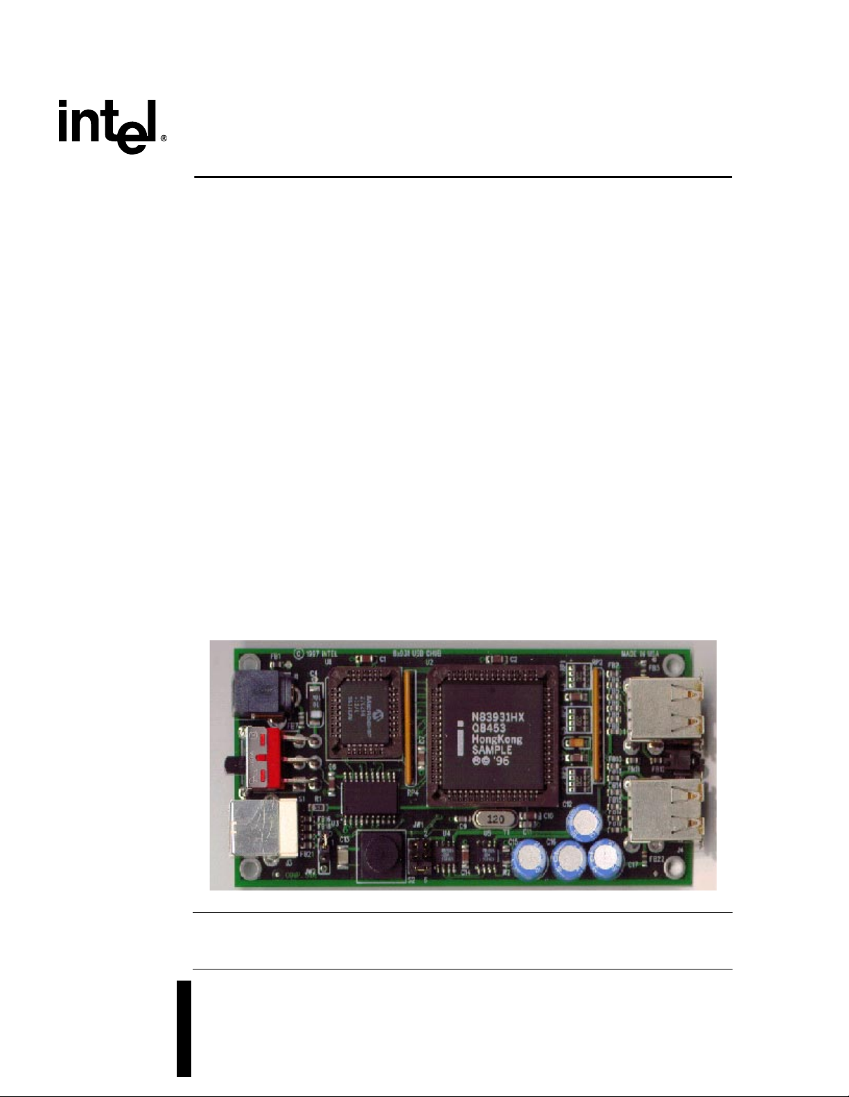
The Intel 8x931HA USB Customer Hub (CHUB) is a hardware reference design for the USB
system designer.
The Intel 8x931HA USB CHUB incorporates a fully functional Intel 8x931HA USB Peripheral
Controller. The CHUB has undergone the same level of testing required of a commercial USB
Hub product, such as USB PlugFest compliance and Intel System Integration and Validation
testing.
■ Hardware Reference Design
—Status LED
—Self/Bus Power Switch Options
—Reset Switch
—Internal Program Memory Option
—Uses High Side Power Switch for USB
Power Management
—provides current limiting
—provides thermal shut down
—500mA minimum continous load
current per channel
This document contains information on products in the sampling and initial production phases of
development. The specifications are subject to change without notice. Verify with your local Intel
sales office that you have the latest datasheet before finalizing a design.
Order Number: 273141-003
June 1998
Page 2

8x931HA USB Customer Hub
Information in this document is provided in connection with Intel products. No license, express or implied, by estoppel or otherwise, to any intellectual
property rights is granted by this document. Except as provided in Intel’s Terms and Conditions of Sale for such products, Intel assumes no liability
whatsoever, and Intel disclaims any express or implied wa r r anty, relating to sale and/or use of Int e l pr oducts in cluding li a bility or warranties relating to
fitness for a particular purpose, merchantability, or infringement of any patent, copyright or other intellectual property right. Intel products are not
intended fo r use in medic al , li f e saving, or life sustaining applications.
Intel may make changes to specifications and product descriptions at any time, without notice.
Designers must not rely on the absence or characteristics of any features or instructions marked "reserved" or "undefined." Intel reserves these for
future definition and shall have no responsibility whatsoever for conflicts or incompatibilities arising from future changes to them.
The 8x931HA USB Customer Hub may contain design defects or errors known as errata which may cause the product to deviate from published
specifications. Current characterized errata are available on request.
Contact your local Intel sales office or your distributor to obtain the latest specifications and before placing your product order.
Copies of documents which have an ordering number and are refere nced in this document , o r ot her Intel literature ma y be obtained by calling 1-800-
548-4725 or by visiting Intel’s website at http://www.intel.com.
Copyright © Intel Corporation, 1997
*Third-party brands and names are the property of their respective owners.
2 Advance Information Datasheet
Page 3

8x931HA USB Customer Hub
Contents
1.0 Introduction..................................................................................................................5
2.0 Board Connector Interface.....................................................................................6
3.0 Functional Description.............................................................................................8
3.1 Self/Bus-Powered Operation.................................................................................8
3.2 Status LED............................................................................................................8
3.3 Internal Program Memory Option..........................................................................8
3.4 External EPROM Enabling or Disabling................................................. .............. .8
3.5 Firmware ...............................................................................................................9
3.6 Design N ot e s............ .. ........... ... ........... .. ............ ........... ... ........... .. ............ .. ...........9
3.6.1 Suspend Current...................................................................................... 9
3.6.2 Input Power Specification.......................................................................10
3.6.3 Overcur re n t T ripping ... ........... ............ .. ........... ... ........... .. ............ .. .........1 0
4.0 Mechanical Data .......................................................................................................11
4.1 Module D ime n sions.... .. .. ............ .. ............ .. ........... ... ........... ............ .. ........... ... ....11
4.2 Plastic Encasing Removal and Assembly Procedures........................................12
4.2.1 Plastic Encasing Removal......................................................................12
4.2.2 Plastic Encasing Assembly ....................................................................12
4.3 Component Specifications...................................................................................12
5.0 Bill of Materials.........................................................................................................13
6.0 Schematics.................................................................................................................15
Figures
1 Intel 8x931HA USB Customer HUB Block Diagram.................................. .. ..........6
2 Top View of CHUB ........................... .. .. .. ................. .................... ..........................6
3 Bottom Label for CHUB Device .............................................................................7
4 Top and Bottom View of CHUB Encasing...........................................................11
5 Device Dimensions..............................................................................................11
Tables
1 Electronic Information............................................................................................5
2 Related Documents...............................................................................................5
3 CHUB Connectors.................................................................................. .............. .7
4 JW2 Jumper Settings ............................................................................................8
5 JW1 Jumper Settings ............................................................................................8
6 Bill of Materials (CHUB Rev. D) .................................................. ........................14
Advance Information Datasheet 3
Page 4

Page 5
1.0 Introduction
The Intel 8x931HA USB Customer HUB (CHUB) is a hardware reference design for the USB
system designer.
The CHUB serves as an evaluation platform and reference design for use in constructing a USB
HUB that incorporates Intel’s 8x931HA USB Peripheral Controller.
This design was built using Intel USB Development Tools. For more information visit Intel on the
web.
Table 1. Electronic Information
8x931HA USB Customer Hub
This document, a s well as a ny upd ates or a ddendums
are available at:
A variety of product information is available at: http://developer.intel .com/design/usb
USB software su pport can be found at : http://developer.intel.com/desi gn/usb/sws up
Intel 8x931HA Customer HUB schematic s http://developer.intel.com/d esign/usb/schems
Intel USB Specification Updates http://developer.intel.com/desi gn/usb/spe cupdt
Information about USB and specifications can be
found at:
Table 2. Related Documents
Document Title Order Number
8x931AA/8x931 HA Universal Serial Bus Per ipheral
Controller D ata s h eet
8x931AA, 8x931HA Universal Serial Bus
Peripheral Controller User’s Manual
Universal Serial Bus Speci f ication, Rev. 1.0
8x931HA Universal Serial Bus Customer Hub
Specification Update
http://developer.intel .com/design/usb/manuals
http://www.usb.org
Intel Order #273108
Intel Order #273102
Intel Order #272904
Intel Order #273155
Advance Information Datasheet 5
Page 6
8x931HA USB Customer Hub
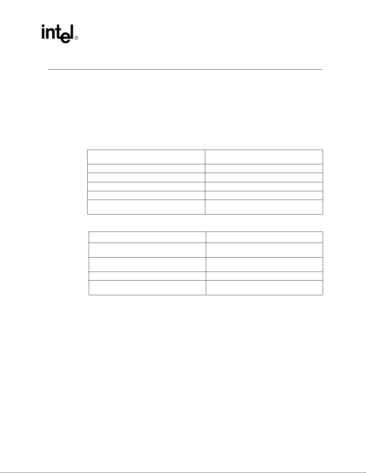
Figure 1. Intel 8x931HA USB Customer HUB Block Diagram
Port0
Upstream
D0-D7
8x931 Hx
Intel USB HUB
AD0-AD7
12 MHz
Clock
Port2
Port3
Port4
Port5
Status
2.0 Board Connector Interface
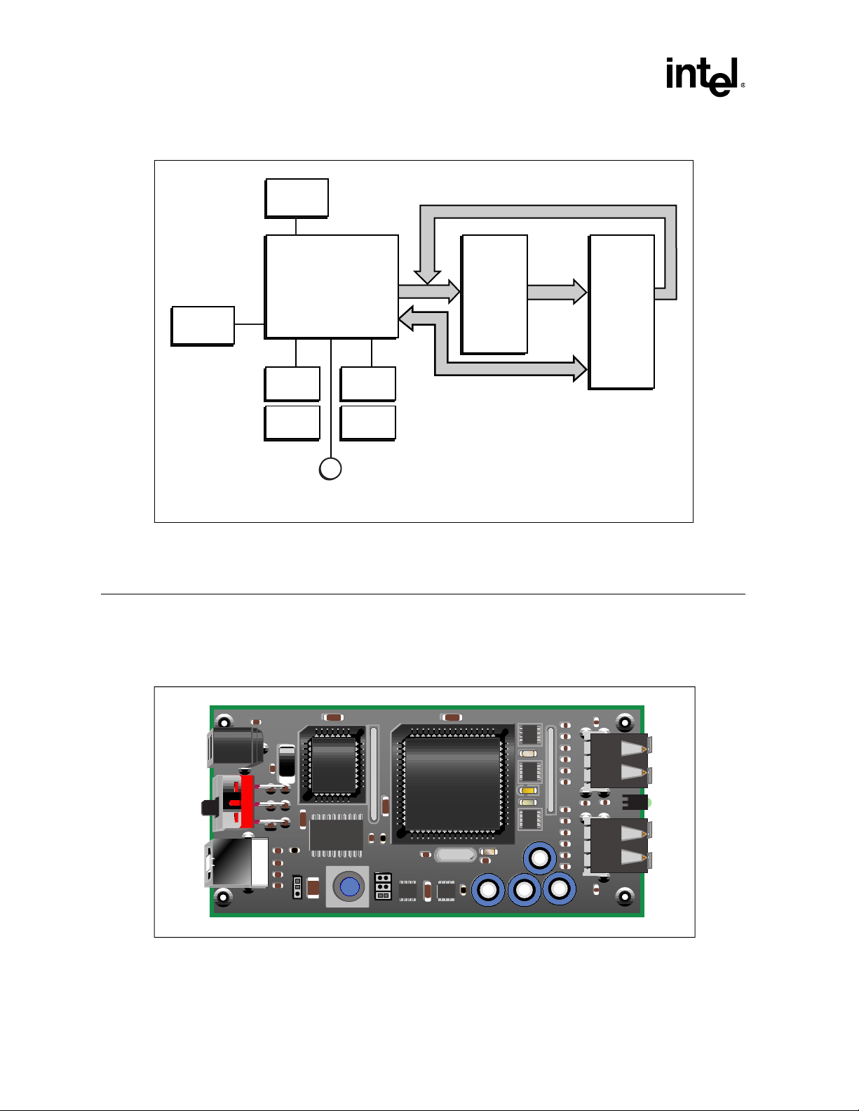
Figure 2 illustrates the major components of the CHUB board. See Section 5.0 for a complete
component list.
Figure 2. Top View of CHUB
74ACT373
Latch
A8-A15
A0-A7
32Kx8
EPROM
A4601-01
FB1
S1
FB7
J3
RP4
C18
U3
R3
JW1
U2
C7
C9
C14
U4
U1
J1
C4
16V
10
C8
R1
FB16
FB18
FB20
C13
FB21
JW2
C2C1
120
C15
U5
R2
C11
C10
RP1
RP5
RP2
C12
C16
FB2
FB4
FB5
FB6
FB7
FB8
FB10
FB13
FB14
FB15
FB17
FB19
C17
FB3
FB22
J2
FB12FB11
CR1
J4
A4539-02
Figure 3 illustrates the connectors available to the user. The CHUB device will have a label on the
bottom resembling Figure 3. Table 3 describes the device connections and their specific types.
6
Advance Information Datasheet
Page 7

Figure 3. Bottom Label for CHUB Device
8x931HA USB Customer Hub
Table 3. CHUB Connectors
Description Connector Type Spec
Power J1
Switch S1 Double-pole/double-throw n/a
UPSTREAM J3 Type B USB connector
Port 2 J4 Type A USB connector Self=500mA/Bus=100mA
Port 3 J4 Type A USB connector Self=500mA/Bus=100mA
Port 4 J2 Type A USB connector Self=500mA/Bus=100mA
Port 5 J2 Type A USB connector Self=500mA/Bus=100mA
Port 2
Port 3
Intel 8x931HA USB Customer HUB
NOT F.C.C. APPROVED
Self Powered:
Bus Powered:
Voltage In:
UpstreamSelf Bus+5 V
500mA/port
100mA/port
5.0V +/-2%
Input power, used for self-powered
mode
Port 4Status
Port 5
A4600-01
5.0 V +/- 2%*
* See “Design Notes” on page 9 for more information on this specification.
Advance Information Datasheet 7
Page 8

8x931HA USB Customer Hub
3.0 Functional Description
The Intel 8x931HA USB Customer Hub supports self-powered and bus-powered configurations.
The CHUB has 1 upstream port, and 4 downstream ports.
3.1 Self/Bus-Powered Operation
The user must decide on which power mode of operation to use. Using the switch, the user can
toggle between Self-Powered Mode and Bus-Powered Mode.Section 3.6.2 explains the different
modes in more detail.
Note: Moving the switch to Self-Powered Mode without a power source will reset the CHUB.
3.2 Status LED
The CHUB provides an oper ation statu s indic ator LED. Thi s stat us LED will star t to bli nk once th e
CHUB is configured as a USB Device. Once configured, the blinking of the LED indicates
execution of code from either internal or external memory.
3.3 Interna l Program Memory Option
Intel’s 8x931HA USB Peripheral hub controller comes preprogrammed with an internal ROM
code which enumerates and configures the hub to a minimal default configuration. To use this
internal ROM the user must:
1.) Carefully remove plastic enclosure. (Refer to Section 4.2)
2.) Refer to Table 4 for memory options.
Table 4. JW2 Jumper Settings
Jumper Mode Description
1-2*
2-3
Externa l EPR OM
(EA#=0)
Internal ROM
(EA#=1)
Customer can use Intel supplied EPROM
(*default position) or thei r ow n EPROM.
Customer can use their own customer mask
ROM for checkout or use I ntel supplied ROM.
3.4 External EPROM Enabling or Disabling
The CHUB provides the us er wit h the capability to ena ble or dis abl e t h e ext er nal EPROM th rou gh
a hardware jumper or by using software. See the following table for more information.
Table 5. JW1 Jumper Settings (Sheet 1 of 2)
Jumper Mode Description
1-2 ROM disabled
8
Advance Information Datasheet
Hardware disabled
(CE# = 1)
Page 9

Table 5. JW1 Jumper Settings (Sheet 2 of 2)
Jumper Mode Description
3-4 ROM enabled
5-6* ROM enabled
3.5 Firmware
The latest release of the 8x931HA firmware can be downloaded from the Intel software support
website listed in Table 1 on page5.
8x931HA USB Customer Hub
Enable or disable via software
(P3.1)
Hardware enabled ( *default positi on)
(CE# = 0)
Refer to Table 1 for the Intel USB Spe cif i cat ion Update websit e location to le ar n about any known
errata for the CHUB
1
specification.
3.6 Design Notes
The CHUB is only intended to provide an evaluation platform and reference design for use in
constructing a USB HUB that will incorporate Intel’s 8x931HA USB Peripheral Controller. The
CHUB is not intended to be a commercial-ready device. The intent of the CHUB is to provide a
starting point to IHVs for de velopmen t of thei r produ cts. User s of the CHUB are respons ible f or all
designs they may create with the CHUB.
Some trade-offs should be noted which were made to incorporate flexibility into the CHUB for
evaluation purposes. Because of this, some items should be noted if this design is to be used as a
base for an actual production hub. These items are listed below and may not be the only items to
consider. Users need to perform thei r own t esting of their designs to ensure that all necessar y U SB
specifications are met.
3.6.1 Suspend Current
THe CHUB is designed to provide the user the flexibility to operate in stand alone mode or in
expanded mode. Stand alone mode is defined as running firmware from on chip ROM. Expanded
mode is defined as running firmware from an external EPROM.
During validation testing in external EPROM mode, the CHUB suspend current was measured at
8.0-10.0 mA. Thi s was pri mar ily du e to th e extr a curr ent dr awn b y the EPROM and la tch. This is i n
violation of USB spec which specifies a maximum suspend current of 500 micro amps. When
running from on-chip ROM, the suspend current was well within spec.
This should not pose a problem because in an actual production hub, the ROM code would reside
in internal memory.
1. As of the printing date of this document, it was discovered that the Microsoft Memphis* Beta 3 operating system was incorrectly using the
values set in the PortPwrCtrlMask field to determine which downstream ports to issue "Set Port Power" commands to upon device
enumeration/configuration. This bug in the beta version, in conjunction with the values reported in the hub’s port power control mask
field, caused the operating system to fail to issue "Set Port Power" commands to the downstream ports on Intel’s 8x931Hx hub peripheral
controller. Refer to http://developer.intel.com/design/usb/specupdt for the prescribed workaround.
.
Advance Information Datasheet 9
Page 10

8x931HA USB Customer Hub
3.6.2 Input Power Specification
CHUB is designed to run from self or bus-powered modes. Self-powered mode allows the user to
plug in a 5 Volt power supply to provide HUB power. Bus-powered mode allows the user to draw
power from the USB cable.
In Self powered mode, Intel has specified the power supply be 5.0 V +/- 2%. Typically, 5V power
supplies do not specify to this tight tolerance. Typical power supplies are +/- 5%. The CHUB will
operate an d r un wit h a 5V +/-5% power supply, but wil l not have the all ocated voltage dr op budget
allowed. Any power supply used should have the ability to provide a minimum of 2 Amps
continuous cur re nt.
The USB system designer is responsible for ensuring that the allocated Vdrop budget meets the
USB specification.
3.6.3 Overcurrent Tripping
The CHUB has been designed t o provid e a .56 0 ms delay upo n overcu rrent det ectio n. This sol ution
has helped to solve the problem of detection of false overcurrent detections (due to hot-plugging)
by delaying the input response to OVRI# by .560 ms.
Intel recommends that the USB system designer pay close attention to the method of detecting
overcurrent protection for USB systems.
10
Advance Information Datasheet
Page 11

4.0 Mechanical Data
4.1 Module Dimensions
This section provi des the physical di mension s for the Intel 8x931HA USB CHUB plas tic enc asing.
Figure 4 shows the top and bottom views of the CHUB encasing. Figure 5 gives the device
dimensions and connector orientations.
Figure 4. Top and Bottom View of CHUB Encasing
Bottom portion
of case
8x931HA USB Customer Hub
Top portion
of case
Figure 5. Device Dimensions
3.0
3.20
20.9
6.0
49.1
Detail 1
13.0
13.2
Detail 1
PCB groove 2x1.5 deep
Logo
10.0
10.0
119.4
3.0
49.1
2mm overhang
2.0
2.0
6.0
5.60 thru
10.240/2mm C-sink
Detail
2
1.5
55.1
Detail 2
7.0
10.0
Detail 2
11.6
4.5
Detail
A4543-01
26.9
3
7.5
12.2
Detail 3
A4545-01
Advance Information Datasheet 11
Page 12

8x931HA USB Customer Hub
4.2 Plastic Encasing Removal and Assembly Procedures
The CHUB uses a molded plastic encasing to protect the PCB. Removing and assembling the
plastic encasing requires some care since there are no screws used in the assembly of the PCB and
the plastic encasing. Refer to Figure 4 for a Top and Bottom view of the CHUB plastic enclosure.
4.2.1 Plastic Encasing Removal
The CHUB is shipped pre-assembled. The following section briefly describes the procedure for
removing the plastic encasing.
To remove the Top portion of the plastic case, the user must orient the CHUB so that the bottom
label is facing the user (upside down). Take ahold of the four corners of the Top portion of the
encasing and gently extend the sides away from the Bottom portion. This extension will cause the
Bottom portion of the encasing to free itself from the Top portion. Gently lift the Bottom portion
out, one side at a time, until the Bottom portion is completely detached from the Top portion. This
frees the PCB from the grooves located on the sides of the Top portion.
Once the top portion is removed, the PCB will sit on the bottom portion. To remove the PCB from
the Bottom portion, the user must gently extend the sides away from the Bottom portion, starting
with the side of the PCB containing the USB connectors. Once this side of the PCB is out of the
Bottom portion of the encasing, the user can lift the PCB out at a 25° angle. Be careful of the
placement of the toggle switch in respect to the Bottom portion. Pulling out the PCB without
angling it may cause damage to PCB and the Bottom portion.
4.2.2 Plastic Encasing Assembly
This secti on br iefly describes the procedure to assemble th e Top and Bott om po rt ions of th e pl as ti c
enclosure to the PCB.
Place the PCB into the Bottom portion, as depicted in Figure 4, at a 25° angle, placing the toggle
switch into its Bottom portion opening. Extend the opposite side of the Bottom portion enough to
lower the PCB into the Bot tom po rtion . Both the toggle swi tch and USB con nec tors sh ould fi t snug
into their respective openings on the Bottom portion.
Note: Be careful with the LED. The user may have to adjust the LED once the above procedure is done.
This can be done by gently pushing the LED into its Bottom portion opening.
Starting from one side, extend the Top portion such that the Top portion grooves can be placed
onto the PCB within the Bottom portion. Perform this procedure on the second side so that both
grooves on the Top portion sides are firmly holding the PCB in place. Gently push down until the
PCB snaps into place, and the Bottom and Top portions are reassembled.
4.3 Component Specifications
The CHUB uses of f-the-sh elf components. Refer to th e specific manufact urer’s d atasheet for
component specifications. See Section 5.0, “Bill of Materials”.
12
Advance Information Datasheet
Page 13

5.0 Bill of Materials
This following table contains the bill of materials used in building the CHUB. Reference the
specific manufacturer’s datasheet for specifications.
Intel does not recommend or endorse any suppliers. The inclusion of this list should not be
construed as a recommendation or an endorsement of these particular suppliers.
8x931HA USB Customer Hub
Advance Information Datasheet 13
Page 14

8x931HA USB Customer Hub
Item
Qty
Reference
Part
Pkg Type
P/D Num
Description11
CR1
LED
551-0207
T-1 Green R/A28
C1,C2,C3,C6,C7,C8,C10,
0.1uF
CC1206
C1206C104M5UAC
50V 20% ceramic chip cap Z5U
C1431C410uF
6032
T491C106K016AS
T491C Tant. chip cap 16 V case-C41C51uF
3216
T491A105K016AS
16V 10% T ant. chip cap case A52
C11,C9
30pF
CC0805
C0805C330J5GAC
50V 5% ceramic chip cap 64
C12,C15,C16,C17
100 uF
PCAPR140-330
94SA107X0016EBP
OSCON Radial Al Elec. 16V71
C13
0.33uF
3528
T491B475M010AS
50V 20% ceramic chip cap Z5U91
C18
1uF
CC1206
C1206C104M5UAC
16V 10% ceramic chip cap 0Z5U1012
FB1,FB2,FB3,FB7,FB9,FB12,
BLM21P300S
CR0805
BLM21P300S
30 ohm 3A 0.03 ohm DCR
FB13,FB14,FB19,FB20,FB21,
FB221110
FB4,FB5,FB6,FB8,FB10,
BLM21B201S
CR0805
BLM21B201S
200 ohm 200mA 0.7 ohm DCR
FB11,FB15,FB16,FB17,FB18121
JW1
CONN6POS
HDR2X3
68692-106
2-row unshrouded header 0.230" pins132
JW1,JW2
shuntna68786-102
Low profile 2-pin shunt clip141
JW2
JMP3POS
JMP3
90726-103
not populated155
JW3,JW4,JW6 ,JW7,JW8
shunt
68786-102
Low profile 2-pin shunt clip161J1CON2
RAPC-722
Phihong PSA-183 supply mate R/A PCB mount172
J4,J2
USB_A_Stacked
787617-2181J3USB_B
USB-B
787780-1
US B Ty pe-B thru -hole193
RP1,RP3,RP5
22 ohm
CRN8/CTS744
744083220JTR
RES ARRAY 22 OHM 8TERM 4RES SMT202
RP2,RP4
15k ohm
SIP10
CSC10A-01-153G
10 pin SIP resistor pack211R11.5k ohm
CR1206
CRCW1206
1/4 W 5% thick film chip resistor221R2470k ohm
CR1206
CRCW1206
1/4 W 5% thick film chip resistor231R3560 ohm
CR1206
CRCW1206
1/4 W 5% thick film chip resistor241S1SW DPDT
1201M2S3AQE2
DPDT Slide Switch R/A PCB mount 6A @ 120V251S2RESET
RESET
KSAOM211
SPST momentary push-button switch no261U132-pin PLCC EPROM
PLCC32
PLCC-32-SMT-TT
32-pin PLCC socket for EPROM271U127C256naTMS27PC256-12FML
32-pin PLCC EPROM281
U2X
SOCKET68naPLCC-68-SMT-TT w/o loc. posts
68-pin PLCC socket surface mount291U28x931HA
SOCKET68na8x931HA USB HUB controller301U374ACT373
SO20W
MC74ACT373AD
Octal transparent latch Advanced CMOS312
U4,U5
MIC2526-2
SO8
MIC2526-2BM
Dual USB power switch321Y112 MHz
XTALV
ATS-49 Standard 12.000 MHz
ATS-49 low profile thru-hole crystal
Table 6. Bill of Materials (CHUB Rev. D)
14
Advance Information Datasheet
Page 15

6.0 Schematics
This section displays schematics for the 8x931HA CHUB board. These schematics are also on the
diskette(s) provided with this kit. These schematics may also be downloaded via the Intel web site
(see Table 1 for URL).
8x931HA USB Customer Hub
Advance Information Datasheet 15
Page 16

P5V
Internal
P5V
3
JW2
2
PSEN_NOT
UPWEN_NOT
External
1
ALE
P0.0
P2.7
P2.6
P2.5
P2.4
P2.3
P2.2
P2.1
P2.0
P0.1
RP1
DGND
P0.2
DP4
123
RDP4
P0.3
DM4
RDM4
P0.4
DP5
678
RDP5
P0.5
DM5
4 5
RDM5
61
62
63
64
65
66
67
68
1
2
3
4
5
6
7
8
9
P0.6
P0.7
22 ohm
P5V
Vss2
ALE
EA#
RP5
Vccp2
Vssp1
DP3
123
RDP3
UPWEN#
PSEN#
DM3
DP2
678
4 5
RDM3
RDM2
RDP2
60
Reserved1
Reserved2
A9/P2.1/KSO9
A8/P2.0/KSO8
10
P0.7
DM2
22 ohm
RP3
123
RDP0
55
58
56
57
59
DP5
DP4
DM5
DM4
Vcc2
A15/P2.7/KSO15
A14/P2.6/KSO14
A13/P2.5/KSO13
A12/P2.4/KSO12
A11/P2.3/KSO11
A10/P2.2/KSO10
AD7/P0.7/KSI7
AD6/P0.6/KSI6
AD5/P0.5/KSI5
AD4/P0.4/KSI4
AD3/P0.3/KSI3
11
12
13
14
15
P0.3
P0.2
P0.6
P0.5
P0.4
P0.0
P0.2
P0.1
P0.3
DP0
DM0
678
22 ohm
4 5
ECAP
RDM0
53
52
54
DP0
DM0
ECAP
Vssp350Vccp151Vssp4
U2
8x931Hx
AD2/P0.2/KSI2
AD1/P0.1/KSI1
AD0/P0.0/KSI0
Vss1
Vcc119P3.0/OVRI#20P3.1/SOF#21P3.2/INT0#22P3.3/INT1#23P3.4/T0/KSO16
16
17
18
P0.0
P0.1
P3.0
P0.7
P0.4
P0.5
P0.6
49
P3.1
48
DP3
P3.2
DM3
ECAP
47
Vssp2
46
24
44
45
DP2
DM2
LED0
P3.5/T1/KSO17
P3.6/WR#/KSO18
25
26
C5
12
+
1uF
CR1
Status
LED1
PLLSEL
RESET
AVcc
XTAL2
XTAL1
LED2
LED3
P1.7/KSO7/TXD
P1.6/KSO6/RXD
P1.5/KSO5
P1.4/KSO4
P1.3/KSO3
P1.2/KSO2
P1.1/KSO1/T2EX
P1.0/KSO0/T2
P3.7/RD#/KSO19
DGND
P0.[0:7]
D
Rev
of
1 2
PWR_MODE
OVRI_NOT
10
9
8
7
6
5
4
3
2
1
RP2
15k ohm
DGND
P5V
LED
2 1
43
42
41
40
39
38
37
36
35
34
33
32
31
30
29
28
27
DGND
C18
1.0 uF
R3
1 2
560 ohm
1 2
P0.0
P5V
123456789
P5V
P0.1
X1
P0.2
P0.3
P0.4
RESET
Y1
P0.5
DGND
RESET
S2
12
C13
12
+
X2
12
12 MHz
1 2
12
P0.6
P0.7
OVRI# open drain
10
0.33uF
C11
C9
CEG System Engineering Boards and ASICs
5000 W. Chandler Blvd.
Chandler, AZ 85226
Intel Corporation
RESET
30pF
30pF
DGND
C3
0.1uF
12
C6
0.1uF
12
C10
0.1uF
12
C7
0.1uF
12
C2
0.1uF
12
P5V
8x931 USB CHUB CPUMEM
DGND
1
DWG NO
CAGE Code
B
Size
JW1
shunt
JW2
shunt
Sheet
Date
Drawn by
U1
Thursday, January 22, 1998
CMJ
U2X
SOCKET68
27C256
P2.[0:7]
D03D14D27D38D413D514D617D7
U3
Q02Q15Q26Q39Q412Q515Q616Q7
A2
A0
DGND
26
17
11
1
18
OC
19
A6A7A4A5A3
O013O114O215O318O419O520O621O7
G
U1
74ACT373
A011A110A29A38A47A56A65A74A829A928A1024A1127A123A1330A1431CE23OE
22
NC212NC4
NC11NC3
Vpp
32-pin PLCC EPROM
2
25
A7A6A5
A3A2A1A1A0
A4
P3.1
RP4
C1
0.1uF
12
C8
0.1uF
12
P5V
15k ohm
DGND
P3.2 High=Self-powered
P3.3 Low=Function
disabled
A[0:7]
P2.4
P2.1
P2.2
P2.5
P2.0
P2.3
P2.6
P5V
ROMNABL_NOT
P3.1
P5V
JW1
DGND
JW1
1 2
3 4
5 6
1-2 ROM Disabled
3-4 ROM Port contrl.
5-6 ROM Enabled
Intel assumes no responsibility for any errors which may
appear in the design. Intel reserves the right to modify
this design without notice.
Page 17

Intel assumes no responsibility for any errors which may
appear in the design. Intel reserves the right to modify
this design without notice.
1 1
PORT-0
A
USB_B
4
UPSTREAM
123
4 4
A
PWR_MODE
OVRI_NOT
3 3
UPWEN_NOT
2 2
Power Input
Pin and
Barrel
ECAP
J1
J3
CON2
1
2
GNDEXT
P5VEXT
1 2
FB21
BLM21P300S
BLM21B201S
DGND
B
C
1 2
DGND
GND
FB18
DGND
1 2
FB20
BLM21P300S
P5VUPSTR
Bus
SW DPDT
C4
10uF
BLM21P300S
DGND
1
354
2
12
3.3 V Pullup
Full speed
1.5k ohm
1 2
1 2
12
R1
BLM21P300S
FB1
Self
6
S1
FB7
P5V
Power Mode
P5V VCC VDD
OVRI_NOT
DGND
4
MIC2526-2
OUTB
GND
5
6
PORTVCC5
ENA1FLGA2FLGB3ENB
OUTA
IN
8
7
PORTVCC4
P5V
12
R2
470k ohm
U5
P5VSWIN
P5V
B
C
DGND
U4
12
C14
0.1uF
4
MIC2526-2
OUTB
GND
5
PORTVCC3
ENA1FLGA2FLGB3ENB
OUTA
IN
7
6
8
PORTVCC2
1 2
BLM21B201S
FB16
D
Size
Drawn by
B
8x931 USB CHUB PORTS
CAGE Code
CMJ
Date
Thursday, January 22, 1998
DWG NO
1
Sheet
E
2 2
of
DP0
DM0
DM4
DP4
1 2
FB4
BLM21B201S
Intel Corporation
CEG System Engineering Boards and ASICs
5000 W. Chandler Blvd.
Chandler, AZ 85226
DGND
1 2
FB5
BLM21B201S
1 2
BLM21P300S
DGND
BLM21B201S
1 2
BLM21P300S
FB2
DOWNSTREAM
100 uF
DM5
DP5
1 2
BLM21B201S
FB6
FB3
B4
USB_A_Stacked
T4
+
12
C15
1 2
FB8
PORT-5
B1B2B3
J2
DGND
T1T2T3
PORT-4
1 2
FB12
BLM21P300S
+
12
C12
100 uF
BLM21P300S
DGND
1 2
DP2
1 2
FB15
BLM21B201S
1 2
BLM21P300S
FB9
DM2
BLM21B201S
FB14
1 2
1 2
BLM21B201S
FB17
1 2
BLM21P300S
USB_A_Stacked
DOWNSTREAM
FB13
B4
T4
DP3
DM3
FB11
DGND
1 2
BLM21B201S
PORT-3
B1B2B3
J4
DGND
T1T2T3
PORT-2
+
12
C17
100 uF
FB10
1 2
BLM21P300S
100 uF
C16
FB22
+
12
1 2
FB19
BLM21P300S
D
E
Rev
D
Page 18

 Loading...