

Page 1

8VM533M-RZ /
8VM533M-RZ-C
Intel® Pentium® 4 Processor Motherboard
User's Manual
Rev. 1003
12ME-VM533MRZ-1003
Copy ri ght
© 2004 GIGABYTE TECHNOLOGY CO., LTD
Copyright by GIGA-BYTE TECHNOLOGY CO., LTD. ("GBT"). No part of this manual may be reproduced or transmitted in any from
without the expressed, written permission of GBT.
Tra demar ks
Third-party brands and names are the property of their respective owners.
Not ice
Please do not remove any labels on motherboard, this may void the warranty of this motherboard.
Due to rapid change in technology, some of the specifications might be out of date before publication of this booklet.
The author assumes no responsibility for any errors or omissions that may appear in this docum ent nor does the author make a
com mitment to update the information contained herein.
Page 2

Feb. 20, 2004
Mother Board
8VM533M-RZ
Feb. 20 ,2004
Motherboard
8VM533M-RZ
Page 3

Preparing Your Computer
Computer motherboards and expansion cards contain very delicate Integrated Circuit (IC) chips. To
protect them against damage from static electricity, you should follow some precautions whenever you
work on your computer.
1. Unplug your computer when working on the inside.
2. Use a grounded wrist strap before handling computer components. If you do not have one,
touch both of your hands to a safely grounded object or to a metal object, such as the power
supply case.
3. Hold components by the edges and try not touch the IC chips, leads or connectors, or other
components.
4. Place components on a grounded antistatic pad or on the bag that came with the components
whenever the components are separated from the system.
5. Ensure that the ATX power supply is switched off before you plug in or remove the ATX power
connector on the motherboard.
Installing the motherboard to the chassis
If the motherboard has mounting holes, but they don't line up with the holes on the base and there
are no slots to attach the spacers, do not become alarmed you can still attach the spacers to the
mounting holes. Just cut the bottom portion of the spacers (the spacer may be a little hard to cut off, so
be careful of your hands). In this way you can still attach the motherboard to the base without worrying
about short circuits. Sometimes you may need to use the plastic springs to isolate the screw from the
motherboard PCB surface, because the circuit wire may be near by the hole. Be careful, don't let the
screw contact any printed circuit write or parts on the PCB that are near the fixing hole, otherwise it
may damage the board or cause board malfunctioning.
Page 4

Table of Contents
English
Chapter 1 Introduction................................................................................................5
Chapter 2 BIOS Setup ............................................................................................. 19
Features Summary...........................................................................................................................5
8VM533M-RZ Series Motherboard Layout......................................................................................6
Block Diagram .................................................................................................................................. 7
Hardware Installation Process ......................................................................................................... 8
Step 1: Install the Central Processing Unit (CPU)..........................................................................8
Step 1-1: CPU Installation .................................................................................................9
Step 1-2: CPU Cooling Fan Installation ............................................................................ 9
Step 2: Install Memory Modules....................................................................................................10
Step 3: Install AGP Card ............................................................................................................... 11
Step 4: Install I/O Peripherals Cables ........................................................................................... 11
Step 4-1: I/O Back Panel Introduction ............................................................................. 11
Step 4-2: Connectors Introduction ...................................................................................12
The Main Menu (For example: BIOS Ver. : F4a).........................................................................19
Standard CMOS Features ............................................................................................................. 21
Advanced BIOS Features .............................................................................................................23
Integrated Peripherals .....................................................................................................................24
Power Management Setup .............................................................................................................26
PnP/PCI Configurations ................................................................................................................. 27
PC Health Status............................................................................................................................28
Frequency/Voltage Control ............................................................................................................. 29
Load Fail-Safe Defaults ................................................................................................................... 30
Load Optimized Defaults ................................................................................................................. 30
Set Supervisor/User Password.....................................................................................................31
Save & Exit Setup .........................................................................................................................32
Exit Without Saving ........................................................................................................................32
Chapter 3 Install Drivers ........................................................................................... 33
- 4 -8VM533M -RZ Series Motherboard
Page 5

Chapter 1 Introduction
Features Summary
CP U — Socket 478 for Intel® Pentium® 4 (Northwood) with HT Technology
— Intel® Pentium® 4 533/40 0MH z FSB
— 2nd cache depen ds on C PU
Chip set — North Brid ge: VIA P4M 266A/ P4M5 33
— South Bri dge: VIA VT823 5/VT823 7R
Me mo ry — 2 184- pin DDR DIM M s ockets, su pports up to 2GB D RAM (Ma x)
— Supports DDR266/D DR200 DIMM
— Suppo rts only 2.5V DD R SDR AM
Slots — 1 AG P s lot 4X ( 1.5V) de vice suppo rt
— 3 PCI slots su pport 33M Hz & PCI 2.2 compliant
On-Board IDE — 2 IDE con troller prov ide IDE HD D/CD-R OM(IDE1 , IDE2) with PIO, Bus
Mas ter (Ultra DMA33/ ATA66/ATA100/ATA133) o peration mo des
— Can c onnec t up to 4 IDE devic es
On-Bo ard F loppy — 1 Floppy port supports 2 FDD with 360K, 720K,1.2M, 1.44M and 2.88M bytes
On-Board P eripherals — 1 Par allel p ort sup ports Norm al/EPP/ECP mode
— 1 Seri al port (CO MA), 1 V GA port, CO MB o nboard
— 6 US B 2.0/1 .1 po rts (4 x Rear, 2 x Fron t by cabl e)
— 1 Front Audi o connec tor
— 1 PS /2 Keyb oard
— 1 PS/ 2 M ouse
On-Bo ard LAN * — Buili t-in VIA 610 3 c hipset *
— 1 RJ 45 port *
On-Board Sound — VIA VT161 6 C ODEC
— Support 2/6 channel
— Line O ut / Line In / Mi c In
— CD In
BIOS — Licen sed AW ARD BIOS
— Supports Q- Flash
I/O Control — ITE8705
Hardware M onitor — CPU Fan Revolutio n de tect
— CPU Fa n Fa il Warni ng
— CPU tem perature detect
— System Voltage Detect
Additional F eatures — Suppo rts @BIOS
— Suppo rts Easy Tune 4
Form Factor — Mi cro ATX size form factor, 2 4.5cm x 20.8cm
™
™
™
English
"*" For 8VM533M-RZ only.
- 5 -
Introduction
Page 6
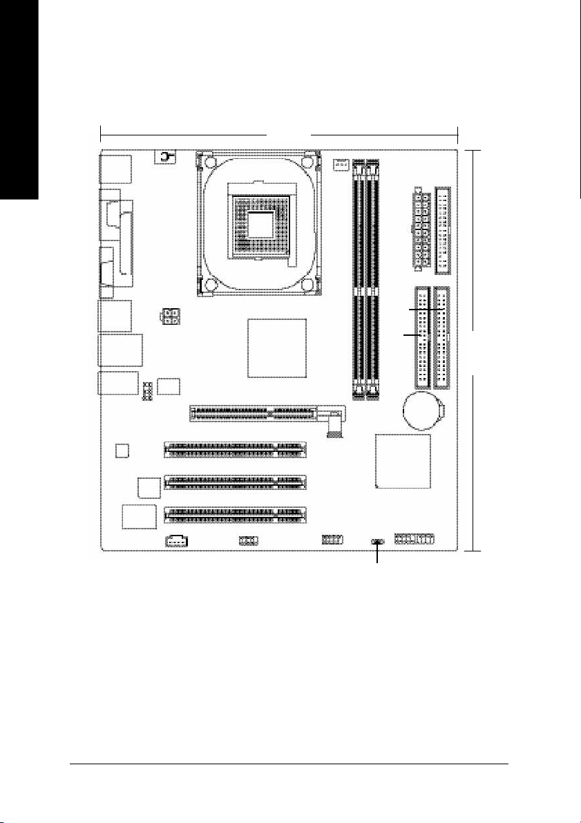
8VM533M-RZ Series Motherboard Layout
English
KB_MS
VGA
R_USB
USB
AUDIO
CODEC
COMA
ITE 870 5
LPT
LAN *
F_AU DIO
BIOS
CD _IN
20.8 c m
#
FD D
AGP
ATX_12 V
VT61 03 *
CPU_FAN
SOC KET 478
8VM533M-RZ
VIA P4M 266A /P4M 533
PCI1
PCI2
PCI3
F_U SB1
COMB
DDR1
DDR2
VI A VT82 3 5/
ATX
IDE1
IDE2
24.5 cm
BAT
VT8 23 7R
F_PANEL
"*" For 8VM533M-RZ only.
"#" For 8VM533M-RZ-C only.
PWR_ LED
- 6 -8VM533M -RZ Series Motherboard
Page 7
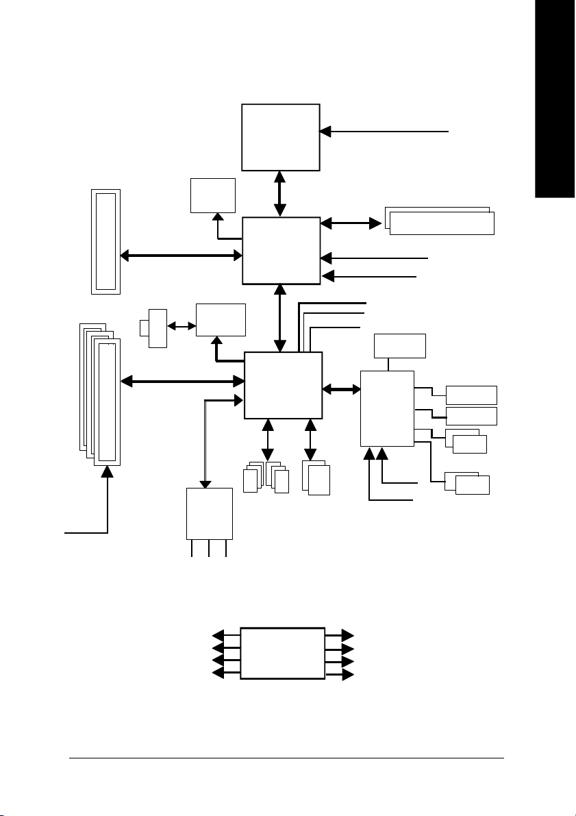
Block Diagram
English
AGP 4X
3 P CI
PCICL K
(33MHz)
AGPC LK
66MHz
RJ45 *
PCI BUS 33MHz
VGA Port
VT6103 *
MII
AC97 Link
6 Chann el
CODE C
MIC
LINE-IN
Pentium 4
Socket 478
CP U
VIA
P4M266A/P4M533
66MHz V_Link
VIA
VT8235/VT8 237R
6 U SB
Ports
LINE-OUT
System Bus
533/400MHz
48 MHz
LPC BUS
ATA33/66/
100/133
IDE Channels
CPUCLK+/- ( 100/133M Hz)
200/266MHz
DDR
MCHCLK (100/133M Hz)
AGPCLK66 MHz
33 MHz
14.318 MHz
BIOS
IT8705
PS/2 KB /Mou se
24 MHz
33 MHz
COM A/COM B
Flop py
LPT Port
PCICLK (33M Hz)
USBCLK (48 MHz)
"*" For 8VM533M-RZ only.
14.318 MHz
33 MHz
CLK
GEN
- 7 -
MCHCLK (100/133M Hz)
CPUCLK+/- ( 100/133M Hz)
AGPCLK (66M Hz)
V_Link (66MHz)
Introduction
Page 8
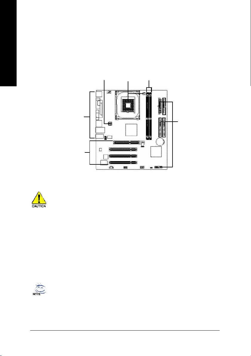
Hardware Installation Process
To s et up your co mp uter, you mus t co mpl ete the following steps:
English
Step 1- Install the Central P rocess ing Unit (CP U)
Step 2- Install mem ory modules
Step 3- Install e xpansi on car ds
Step 4- C onnec t ribbo n c ables , ca binet wires, and power supp ly
Step 4
Step 1
Step 2
Step 4
Step 4
Step 3
Step 1: Install the Central Processing Unit (CPU)
Before i nstalling the p rocess or, adh ere to the following warning:
1. Pleas e m ake sure the CPU type i s supp orted by the m otherboard.
2. The p rocess or will over heat without the he atsink an d/or fan, resul ting i n perm anent
irreparable dam age.
3. If you do not match the CP U socke t Pin 1 and CPU cut edge well, it will caus e im proper
installation. Please change the in sert orientation.
4. Apply therma l grea se between the proce ssor a nd cooling fan.
5. Never run the pro cessor without the he atsink p roperl y and firmly attached . Perm anent
dam age will resul t.
6. Pleas e set the CPU hos t frequency in accorda nce with your pr ocessor 's spe cifications.
We don' t recomm end you to set the system bus frequency over the CPU's specification
becau se these specific bus frequenc ies are no t the standard specifica tions for CPU,
chipset and mos t of the periphe rals. Wh ether your s ystem ca n ru n under these specific
bus freq uencies pr operly will depe nd on your hardware configura tions, includ ing CP U,
Me mo ry, Card s… etc.
HT fu nctio nality re quir ement c ontent :
Ena bl ing the fun ctio nal ity of H yp er- Thr ea din g Techn ol ogy for your c om puter system
requir es all o f the following pla tform com ponents:
- CP U: An Intel® Pen tium 4 Proce ssor with HT Techno logy
- Ch ipset: An VIA Chi pset that supp orts HT Techno logy
- BIOS: A BIOS that su pports HT Technol ogy an d has it enabled
- OS: An op eration s ystem that has optim izations for HT Techn ology
- 8 -8VM533M -RZ Series Motherboard
Page 9
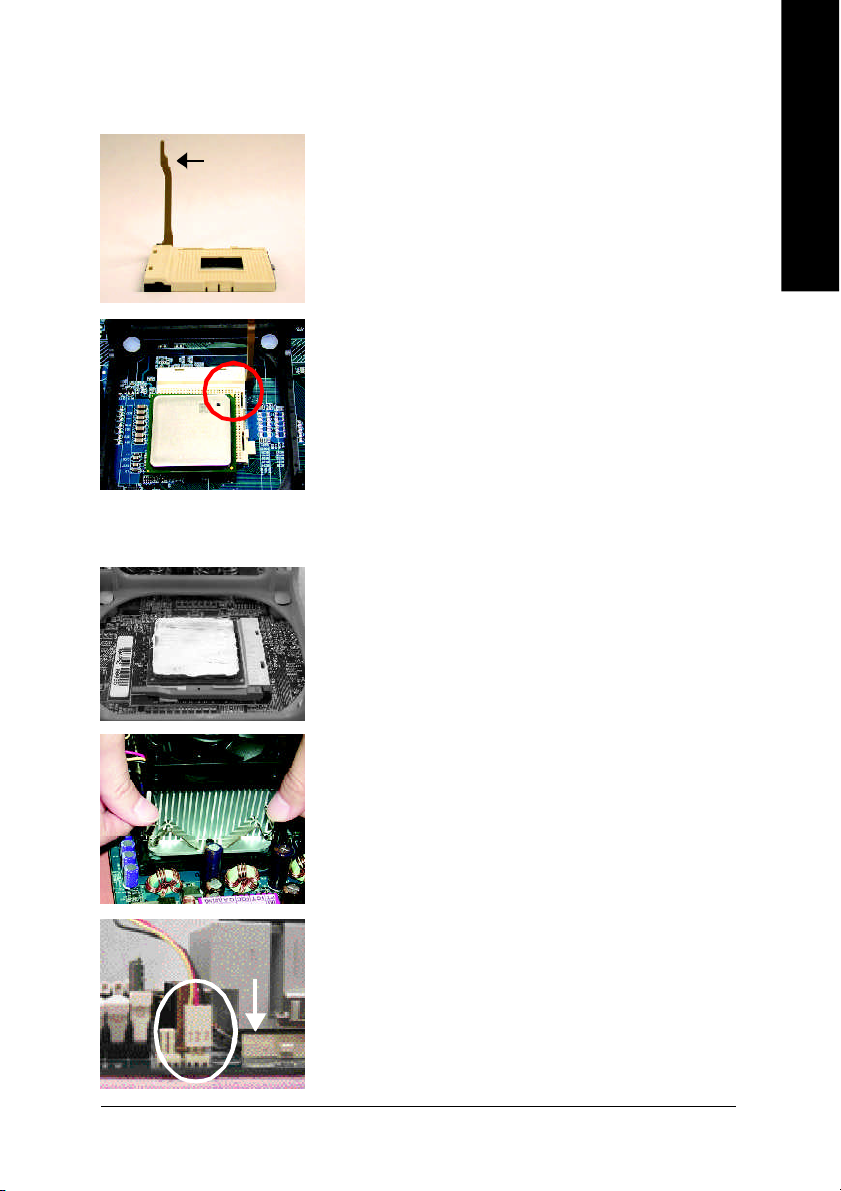
Step 1-1: CPU Installation
English
Socket
Actuation
Lever
Figure 1.
Pull the r od to the 9 0-degree directly.
Figure 2.
Locate Pin 1 in the s ocket an d loo k for a (golde n) cu t edge on the
CPU up per corn er. Insert the C PU into the soc ket. (Do not force the
CPU i nto the sock et.) Then mov e the s ock et l eve r to the locke d
position while ho lding pressure on the c enter of the CPU.
Step 1-2: CPU Cooling Fan Installation
Figure 1.
Apply the therm al tape(or grease) to provide better heat conduction
between you r CP U a nd c oolin g fan.
Figure 2.
Fasten the coo ling fan suppor ting-base o nto the CPU socket on the
motherboard.
Figure 3.
Ma ke sur e the CPU fan is plugg ed to the CPU fan co nnector, than
install c omp lete.
- 9 - Har dware Installation Process
Page 10
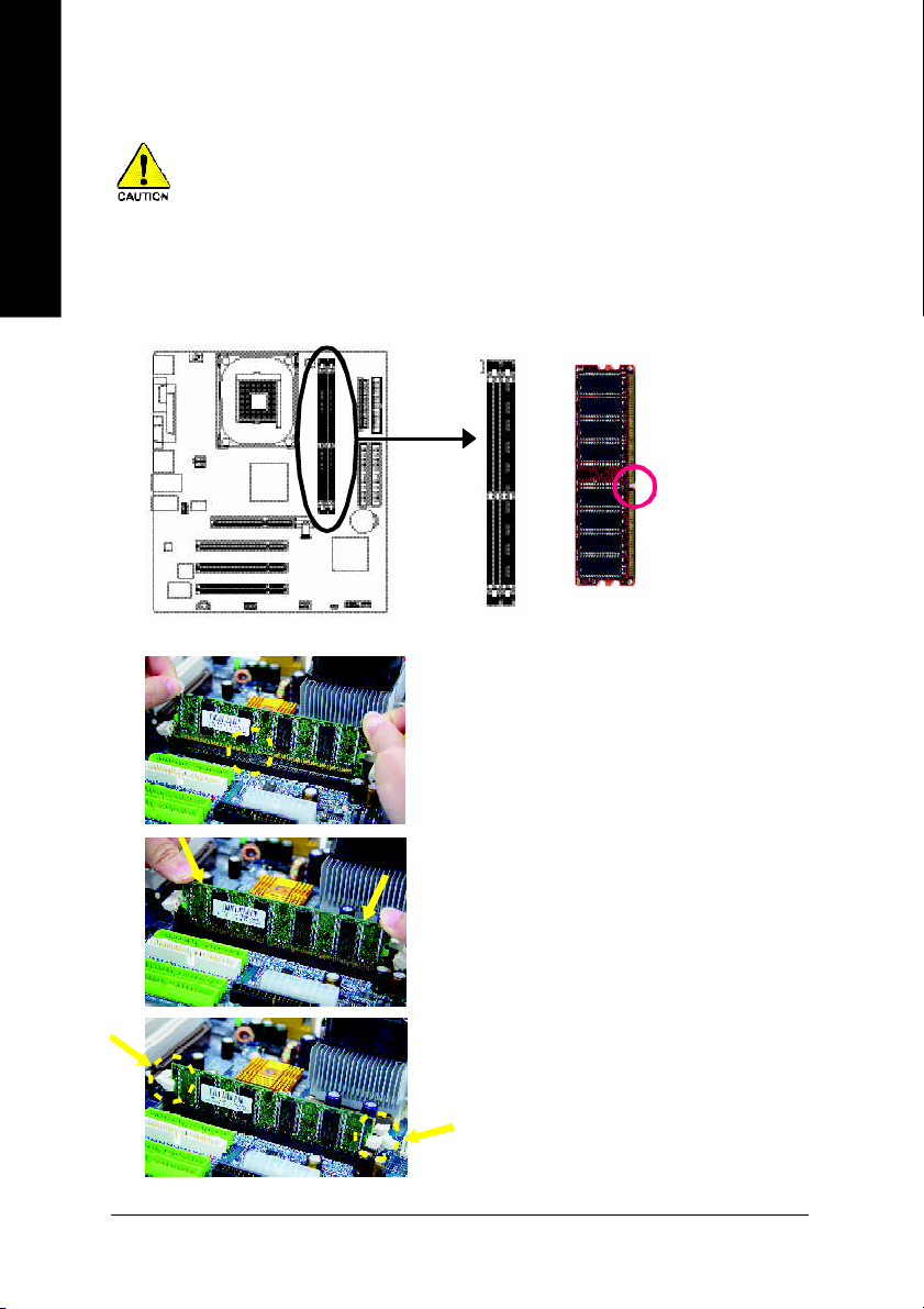
Step 2: Install Memory Modules
English
The mother boar d ha s 2 du al inl ine mem ory m odul e (DIM M) s ocke ts. Th e BIOS wil l autom atica lly
detects me mo ry type and siz e. To instal l the mem ory mo dule , just p ush it ve rtical ly into the DIMM
socket. The DIM M m odule can only fit in one direction due to the notch. Mem ory size c an vary between
soc ke ts.
Before i nstalling the m emory modules, adhere to the following warning:
1. Please note that the DIMM m odule can onl y fit in one di rection due to the one notch.
Wrong o rientation will cause im proper installation. Please change the insert orientation.
Notch
DDR
1. The DIMM sock et has a notch, so the DIM M
me mor y mo dule can o nly fit in one d irection.
2. Insert the DIMM m em ory m odule ver tically in to
the DIM M soc ket. The n pus h i t down.
3. Close the pl astic c lip at both e dges of the DIMM
sockets to lo ck the DIMM m odule.
Reve rse the installation steps when yo u wish to
rem ove the DIMM modu le.
- 10 -8VM533M -RZ Series Motherboard
Page 11
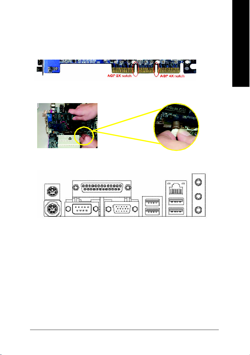
Step 3: Install AGP Card
1. Read the relateAGP card's instruction document before install the AGP card into the computer.
2. If your AG P card has "AGP 4X (1.5V) notch" (show below), please ma ke sure your AGP c ard is AGP
4X(1.5V).
3. Plea se car efully pull out the small white- drawabl e bar at the end of the AG P slot when you try to
install/ U ninstall the AGP ca rd. Ple ase alig n the AGP card to the onboard AGP slot and pr ess firm ly
down on the slot .M ake s ure you r AGP card is lock ed by the small white- drawab le ba r.
Step 4: Install I/O Peripherals Cables
Step 4-1: I/O Back Panel Introduction
u
v
z *
|
English
y
w
x
{
u PS/2 Keyboard and PS/2 Mouse connector
This connec tor supp orts s tandard P S/2 ke yboard and PS/2 m ouse.
v Parallel port (LPT)
Devic e like printer can b e conne cted to Pa rallel port.
w Serial port (COMA)
Mo use and mode m e tc. can be conn ected to Serial port.
x VGA port
Mo nitor can b e conne cted to VGA port.
y/{ USB port
Before you conn ect you r d evice (s) i nto USB connector( s), p lease m ake sure yo ur de vice( s)
such as USB k eyboa rd, m ous e, scann er, zi p, sp eaker. ..etc. Have a stand ard USB interface.
Also m ake sure your OS supports USB controller. If your OS does not support USB controller,
please contact OS ve ndor for possi ble patch o r drive r upgra de. For m ore i nformation please
contact y our OS or dev ice( s) ven dors .
"*" For 8VM533M-RZ only.
- 11 - Hardware Installation Proc ess
}
~
Page 12
z LAN port *
| Line In jack
English
} Line Out jack
~ MIC In jack
Step 4-2: Connectors Introduction
LAN is fast Ethernet with 10/10 0M bps sp eed.
Devi ces l ike CD-R OM , walkm an etc. can be connect to Line In jack.
Connec t the stereo speak ers or earphone to this c onnector.
Mi crophon e can be c onnect to M IC In jac k.
After installation of the audio driver, you are able to use 2 /4/6-channel audio feature by software
selection . You can connect "Fron t speaker" to "Li ne Out" ja ck, Con nect " Rear sp eaker" to
"Line In" jack an d conn ect "Center /Subwoofer" to "M IC In" jac k.
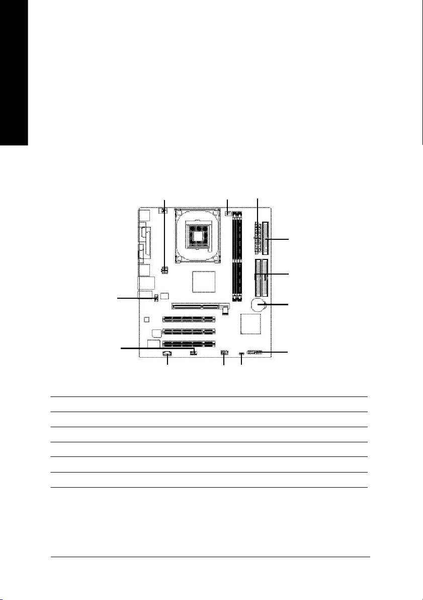
1
3
2
4
5
12
1) ATX_12V
2) ATX
3) CPU_FAN
4) FDD
5) IDE1 / IDE2
6) BAT
"*" For 8VM533M-RZ only.
9
8
10
11
6
7
7) F_PANEL
8) PWR_LED
9) F_AUDIO
10) CD_IN
11) F_USB1
12) COMB
- 12 -8VM533M -RZ Series Motherboard
Page 13

1) ATX_12V (+12V Power Connector)
This c onnector ( ATX_12V) supp lies the C PU oper ation voltage (V core).
If this "ATX_1 2V con nector" i s no t connected, system c annot boo t.
English
432
1
Pin No. Definition
1 GND
2 GND
3 +12V
4 +12V
2) ATX (ATX Power)
AC p ower cord shou ld onl y be connected to you r power s upply u nit after ATX power cab le a nd
other rela ted devices are firm ly connec ted to the main board.
20
11
1 3.3V
2 3.3V
3 GND
4 VCC
5 GND
6 VCC
7 GND
8 Power Good
10
9 5V SB (stand by +5V)
10 +12V
Pin No. Definition
1
Pin No. Definition
11 3.3V
12 -12V
13 GND
14 PS_ON(soft on/off)
15 GND
16 GND
17 GND
18 -5V
19 VCC
20 VCC
3) CPU_FAN (CPU Fan Connector)
Pleas e note, a proper ins tallation of the CPU coo ler is essential to pre vent the CPU from runni ng
unde r abn orm al con dition or dam age d by overh eating . T he C PU fan con nector supports Ma x.
current up to 600 m A.
Pin No. Definition
1
1 GND
2 +12V
3 Sense
- 13 - Hardware Installation Proc ess
Page 14

4) FDD (Floppy Connector)
English
5) IDE1 / IDE2 (IDE1 / IDE2 Connector)
Pleas e conne ct the floppy drive ribbon cab les to FD D. It supp orts 360K, 1.2M , 720 K, 1.44M and
2.8 8M bytes flo ppy disk typ es.
The r ed stripe of the ri bbon ca ble m ust be the sam e side with the Pin1.
34
Impor tant Notice: Please c onnec t first har d dis k to IDE 1 and conne ct CD -ROM to IDE2. The red
stripe o f the ribb on cab le m ust be the sam e side with the Pin1.
33
2
1
6) BAT (BATTERY)
40
39
IDE1IDE2
2
Danger of explosion if battery is incorrectly replaced.
Replace only with the same or equivalent type recomm ended by the
manufacturer.
Dispose of used batteries ac cording to the manufacturer's instructions.
If you want to erase CMOS...
1. Turn OFF the computer and unplug the power cord.
2. Remove the battery, wait for 30 second.
3. Re-install the battery.
4. Plug the power cord and turn ON the com puter.
- 14 -8VM533M -RZ Series Motherboard
1
+
CAUTION
Page 15

7) F_PANEL (2 x 10 pins Connector)
Please c onnect the power LED, PC speaker, r eset switch and power switch etc of your chas sisfront
panel to the F _PANEL connec tor accor ding to the pin assignm ent belo w.
Sof t Po wer
Messa ge L ED/
Po wer/
Slee p LED
MSG+
MSG-
1
1
2
1
1
IDE H ard Disk Acti ve LE D
HD-
HD+
HD (IDE Hard Disk Active LED) Pin 1: LED anode(+)
Pin 2: LED cathode(-)
SPK (Speaker Connector) Pin 1: VCC(+)
Pin 2- Pin 3: NC
Pin 4: Data(-)
RES (Reset Switch) Open: Normal Operation
Close: Reset Hardware System
PW (Soft Power Connector) Open: Normal Operation
Close: Power On/Off
MSG (Message LED/ Power/ Sleep LED) Pin 1: LED anode(+)
Pin 2: LED cathode(-)
NC NC
PW+
RES-
PW-
1
RES+
Connect or
NC
SPEAK+
1
Res et Swi tch
Speak er Co nnector
SPEAK-
20
19
English
8) PWR_LED
PWR_ LED is con nect with the system power indica tor to ind icate whether the sys tem is on/ off.
It will bl ink when the system enters susp end m ode. If yo u use du al color LED, p ower LED will turn
to another colo r.
Pin No. Definition
1
- 15 - Hardware Installation Proc ess
1 MPD+
2 MPD-
3 MPD-
Page 16

9) F_AUDIO (Front Audio Connector)
English
10) CD_IN (CD In Connector)
In order to utiliz e the front audi o heade r, your c hassis mus t have front audio connec tor. Also
please ma ke sure the pin assigm ent on the cable is the same as the pin assigment on the MB
heade r. To find out if the chass is you are b uying supp ort front audio conne ctor, ple ase co ntact
your dealer . Pleas e n ote, you can ha ve the alternative of using front aud io con nector or of usi ng
rear a udio c onnector to play sound.
Pin No. Definition
1 MIC
2 GND
3 REF
10
9
1
2
4 Power
5 Front Audio (R)
6 Rear Audio (R)
7 Reserved
8 No Pin
9 Front Audio (L)
10 Rear Audio (L)
Connec t CD-ROM or DVD -ROM audio out to the conn ector.
Pin No. Definition
1 CD-L
2 GND
1
3 GND
4 CD-R
11) F_USB1 (Front USB Connector)
Be ca reful with the pol arity of the front USB c onnector . Chec k the pin assign me nt car efully whi le
you con nect the front USB c able, in correct conne ction between the cable and connector will m ake
the dev ice unab le to work or even dam age i t. Fo r option al front USB cable, plea se contact yo ur
local d ealer.
Pin No. Definition
1 Power
2 Power
3 USB DX-
2 10
1 9
- 16 -8VM533M -RZ Series Motherboard
4 USB Dy-
5 USB DX+
6 USB Dy+
7 GND
8 GND
9 No Pin
10 NC
Page 17

12) COMB (COM B Connector)
Be car eful with the polar ity of the COMB connec tor. Check the pin assignm ent while you connect
the COM B cab le. Pleas e contact you r neare st dealer for op tional CO MB c able.
Pin No. Definition
1 NDCDB-
2 NSINB
2
1 9
10
3 NSOUTB
4 NDTRB-
5 GND
6 NDSRB-
7 NRTSB-
8 NCTSB-
9 NRIB-
10 No Pin
English
- 17 - Hardware Installation Proc ess
Page 18

English
- 18 -8VM533M -RZ Series Motherboard
Page 19

Chapter 2 BIOS Setup
BIOS Setup is an overvie w of the B IOS Setup Program. The progr am that allows user s to modify the
basic system configuration. This type of information is stored in batter y-backed CM OS RAM so that it
retains the Setup information when the power is turned off.
ENTERING SETUP
Powering ON the computer a nd pressing <Del> immediately will allow you to enter Setup. If you require
more adv a nced BIOS s ettings , p leas e go to " Adv a nc ed B IOS" s etting m e nu. To e nter
Advanced BIOS setting menu, press "Ctrl+F1" key on the BIOS screen.
CONTROL KEYS
< >< >< >< > Move to select item
<Enter> Select Item
<Esc> Main Menu - Quit and not save changes into CMOS Status Page Setup Menu
and Option Page Setup Menu - Ex it current page and return to Main Menu
<+/PgUp> Increase the numeric value or make changes
<-/PgDn> Decrease the numeric value or make changes
<F1> Gener al help, only for Status Page Setup Menu and Option Page Setup Menu
<F2> Item Help
<F5> Restore the previous CMOS value from CMOS, only for Option Page Setup Menu
<F6> Load the file -safe default CMOS v alue from BIOS default table
<F7> Load the Optim ized Defaults
<F8> Q-Fl ash utility
<F9> Sy stem Inform ation
<F10> Save all the CMOS changes, only for Main Menu
Main Menu
The on-line description of the highlighted setup function is displayed at the bottom of the screen.
Status Page Setup Menu / Opti on Page Setu p Menu
Press F1 to pop up a small help window that describes the appropriate keys to use and the possible
selections for the highlighted item. To exit the Help Windo w press < Esc>.
English
The Main Menu (For example: BIOS Ver. : F4a)
Once y ou enter Aw ard BIOS CMOS Setup Utility, the Main Menu (as figure below) w i ll appear on the
screen. The Ma in Menu allows y o u to select from eight setup func tions and two ex i t choices. Use
arrow key s to select among the items and pre ss <Enter > to accep t or enter the sub-menu.
CMOS Setup Utility-Co pyright (C) 1984 -2003 Award Soft ware
} Standard CMOS Feat ures
} Advanced BIOS Feat ures
} Integrated Periphe rals
} Power Management S etup
} PnP/PCI Configurat ions
} PC Health Status
} Frequency/Voltage Con trol
ESC: Quit higf: Selec t Item
F8: Q- Flash F10: Save & Exit S etup
Time, Date, Hard Disk Ty pe...
Load Fail-Safe Defa ults
Load Optimized Defa ults
Set Supervisor Pass word
Set U ser Password
Save & Exit Setup
Exit Without Saving
- 19 - BIOS Setup
Page 20

If you can't find the setting you want, please press "Ctrl+F1" to search the advanced
option hidden.
English
• Standa rd CMOS Features
• Adv anced BIOS Features
• Integr ated Peripherals
• Power Management Setup
• PnP/PC I Configuration
• PC Healt h Status
• Frequen cy/Voltage Control
• Load F ail-Safe Defaults
• Load O ptimized Defaults
• Set Su pervisor Password
• Set U ser Password
• Sav e & Exit Setup
• Exit Without S aving
This setup page includes all the items in standard compatible BIOS.
This setup page includes all the items of Award spe cial enhanced features.
This setup page includes all onboa rd peripherals.
This setup page includes all the items of Green function features.
This setup page includes all the configurations of PCI & PnP ISA resources.
This setup page is the System auto detect Temperature, voltage, fan, speed.
This setup page is control CPU clock and frequency r atio.
Fail-Safe Defaults indicates the value of the sys tem parameters which the system would be in safe
configuration.
Optimized Defaults indicates the value of the system parameters w hich the system would be in
best performance configuration.
Change, set, or disable passw ord. It allow s you to limit access to the system and Setup, or just
to Setup.
Change, set, or disable passw ord. It allow s you to limit access to the system.
Save CMOS v alue settings to CMOS and ex it setup.
Abandon all CMOS v alue changes and exit setup.
- 20 -8VM533M-RZ Series Motherboard
Page 21

Standard CMOS Features
CMOS Setup Utility-Co pyright (C) 1984 -2003 Award Soft ware
Date (mm:dd:yy) Fri, Jan 9 2004
Time (hh:mm:ss) 22:3 1:24
} IDE Primary M aster [No ne]
} IDE Primary S lave [No ne]
} IDE Secondary M aster [No ne]
} IDE Secondary Slave [No ne]
Driv e A [1.44M, 3.5"]
Driv e B [No ne]
Floppy 3 Mode Support [Disa bled]
Halt On [All, But Keyboard]
Base M emory 640K
Exte nded Memory 127M
Total Memory 128M
higf: M ove Enter: Select +/-/ PU/PD: Value F10: Save ESC: Exit F1: General Help
F5: P revious Values F6: Fail-Safe De fault F7: Optimized Defa ults
Date
The date format is <week>, <month>, <day>, <y ear>.
Week The w eek, from Sun to Sat, determin ed by the BIOS and is display only
Month The m onth, Jan. Through Dec.
Day The d ay, from 1 to 31 (or the maxi mum allowed in the month)
Year The year, from 1999 through 2098
Time
The times format in <hour> <m inu te> <second>. The time is c alc ulated base on the 2 4-hour
military-time clock. For ex ampl e, 1 p.m. is 13:00:00.
IDE Primary Master, Slave / IDE Secondary Master, Slave
The category id entifies the types o f hard d isk from driv e C to F that has been i nsta lled in the
computer. There are two types: auto type, and manual type. Manual type is user-definable; Auto type
which w ill automatically d etect HDD type.
Note that the spec ifications of your driv e must match w ith the driv e table. The hard disk w ill not work
properly if y ou enter improper information for this category .
If y ou select User Ty pe, related information will be asked to enter to the follow ing items. Enter the information
directly from the keyboard and press <Enter>. Such information should be provided in the documentation form your hard disk v endor or the system manufacturer.
Cylinder Number of cylinders
Head Number of heads
Precomp Write precomp
Landing Zone Landing zone
Sector Number of sectors
If a hard disk has not been installed, select NONE and press <Enter>.
Stan dard CMOS Feat ures
Item Help
Menu L evel}
Chan ge the day, mo nth,
year
<We ek>
Sun. t o Sat.
<Mon th>
Jan. t o Dec.
<Day>
1 to 31 (or maximum
allowe d in the month)
<Ye ar>
1999 t o 2098
English
- 21 - BIOS Setup
Page 22

computer.
English
Drive A / Dri v e B
The category ide ntifies the types of floppy di sk drive A o r drive B that has been installed in the
None No floppy driv e installed
360K, 5.25" 5.25 inch PC-ty pe standard driv e; 360K byte capacity.
1.2M, 5.25" 5.25 inch AT-ty pe high-density drive; 1.2M by te capacity
(3.5 inch whe n 3 Mode is Enabled).
720K, 3.5" 3.5 inch double-sided driv e; 720K byte capacity
1.44M, 3.5" 3.5 i nch double-sided drive; 1.44M by te capacity.
2.88M, 3.5" 3.5 i nch double-sided drive; 2.88M by te capacity.
Floppy 3 Mode Support (f or Japan Area)
Disabled Normal Floppy Drive. (Default value)
Driv e A Drive A is 3 mode Floppy Driv e.
Driv e B Drive B is 3 mode Floppy Driv e.
Both Drive A & B are 3 mode Floppy Drives.
Halt on
The category determines w hether the computer w ill stop if an error is d etected d uring power up.
No Errors The sy stem boot w ill not stop for any error that may be detected and you
will be promp ted.
All Errors Whenever the BIOS detects a non-fatal error the system will be stopped.
All, But Keyboard The sy stem boot will not stop for a key board error; it will stop for all other
errors. (Default value)
All, But Diskette The system boot will not stop for a disk error; it will stop for all other errors.
All, But Disk/Key The sy stem boot will not stop for a keyboard or disk error; it will stop for all
other errors.
Memory
The category is display -only w hi ch is determined by POST (Pow er On Self Test) of the BIOS.
Base Memory
The POST of the BIOS will determine the amount of base (or conv entional) memory installed
in the system.
The value of the base memory is typically 512K for sy stems with 512K memory installed on
the motherboard, or 640K for systems with 640K or more memory installed on the motherboard.
Extended Memory
The BIOS determines how much ex tended me mory is present during the POST.
This is the amount of memory located abov e 1 MB i n the CPU's memory address map.
- 22 -8VM533M-RZ Series Motherboard
Page 23

Advanced BIOS Features
CMOS Setup Utility-Co pyright (C) 1984 -2003 Award Soft ware
Firs t Boot Device [Flo ppy]
Seco nd Boot Device [HDD -0]
Thir d Boot Device [CDR OM]
Pas sword Check [Set up]
CPU H yper-Threading
higf: M ove Enter: Select +/-/ PU/PD: Value F10: Save ESC: Exit F1: General Help
F5: P revious Values F6: Fa il-Safe De fault F7: Optimized Defa ults
#
" # " System wi ll detect automatically and s how up when you ins tall the Intel® Pentium® 4
processor w ith HT Technology.
First / Second / T hird Boot Device
Floppy Select your boot devic e priori ty by Floppy .
LS120 Select your boot devi ce priority by LS120.
HDD- 0~3 Selec t y our boot device priority by HDD-0~3.
SCSI Select your boot device pr iority by SCSI.
CDROM Selec t your b oot device priority by C DROM.
ZIP Select your boot device p riority by ZIP.
USB-FDD Select your b oot dev ice priority by USB -FDD.
USB-ZIP Select your boot devic e priority by USB-ZIP.
USB-CDROM Selec t your bo ot dev ice priority by USB-C DROM.
USB-HDD Select your b oot devic e priority by USB -HDD.
LAN Select your boo t dev ice p riority by LAN.
Disabled Select your bo ot device priority by Disabled.
Password Check
System The system can not boot and can not access to Setup pa ge will be denied if the
correct password is not entered at the prompt.
Setup The system w il l boot, but access to Setu p will be denied if the correct password
is not entered at the prompt. (Default v alue)
CPU Hyper-Thre ading
Enabled Enables CPU Hyper Threading Feature. Please note that this feature is only w orking
Disabled Disables CPU Hy per Threa ding.
for operating system with multi processors mode supported. (Default value)
Adva nced BIOS Feat ures
[Enab led]
Item Help
Menu L evel}
Selec t Boot Device
prio rity
[Flo ppy]
Boot from floppy
[LS1 20]
Boot from LS120
[HDD -0]
Boot from First HDD
[HDD -1]
Boot from Second HDD
English
- 23 - BIOS Setup
Page 24

Integrated Peripherals
English
CMOS Setup Utility-Co pyright (C) 1984 -2003 Award Soft ware
OnChi p IDE Channel0 [Enab led]
OnChi p IDE Channel1 [Enab led]
AC97 Audio [Au to]
VIA o nboard LAN
USB 1 .1 Controller [Enab led]
USB 2 .0 Controller [Enab led]
USB K eyboard Support [Disa bled]
USB M ouse Support [Disa bled]
Onboar d Serial Port 1 [3F8/ IRQ4]
Onboar d Serial Port 2 [2F8/ IRQ3]
Onboar d Parallel Port [378/ IRQ7]
Paral lel Port Mode [SPP]
higf: M ove Enter: Select +/-/ PU/PD: Value F10: Save ESC: Exit F1: General Help
F5: P revious Values F6: Fa il-Safe De fault F7: Optimized Defa ults
*
Inte grated Periphe rals
[Enab led]
Item Help
Menu L evel}
[Au to]
Auto -detect IDE
cable type
[ATA 66/100/133]
Set C onductor cable
to AT A66/100/133(80
-pi ns)
[ATA 33]
Set C onductor cable
to AT A33(40-pins)
OnChip IDE Channel0
When enabled, allows y ou to use the onboard primary PCI IDE. If a hard disk controller card is
used, set at Disabled.
Enabled Enable onboard 1st channel IDE port. (Default value)
Disabled Disable onboar d 1st channel IDE port.
OnChip IDE Channel1
When enabled, allows you to use the onboard secondary PCI IDE. If a hard disk controller card is
used, set at Disabled.
Enabled Enable onboard 2nd cha nnel IDE port. (Default v alue)
Disabled Disable onboar d 2nd channel IDE port.
AC97 Audio
Auto Enable onboard AC'97 a udio fun ction. (Default v alue)
Disabled Disable this function.
VIA onboard LAN *
Enable Enable onboard LAN function.(Default v alue)
Disable Disable onboard LAN function.
USB 1.1 Controller
Disable this option if you are not using the onboard USB feature.
Enabled Enable USB1.1 Controller. (Default v alue)
Disabled Disable USB1. 1 Controller.
USB 2.0 Controller
Disable this option if you are not using the onboard USB 2.0 feature.
Enabled Enable USB 2.0 Controller. (Default v alue)
Disabled Disable USB 2. 0 Controller.
"*" For 8VM533M-RZ o nly.
- 24 -8VM533M-RZ Series Motherboard
Page 25

USB Keyboard Support
Enabled Enable USB key board sup port.
Disabled Disable USB ke yboard su pport. ( Default v alue)
USB Mouse Support
Enabled Enable USB mouse supp ort.
Disabled Disable USB m ouse sup port. (Default v alue)
Onboard Serial Port 1
Auto BIOS will automatically setup the port 1 address.
3F8/IRQ4 Enabl e onboard Serial port 1 and address is 3F8. ( Default v alue)
2F8/IRQ3 Enabl e onboard Serial port 1 and address is 2F8.
3E8/IRQ4 Enabl e onboard Serial port 1 and address is 3E8.
2E8/IRQ3 Enabl e onboard Serial port 1 and address is 2E8.
Disabled Disable onboard Serial port 1.
Onboard Serial Port 2
Auto BIOS will automatically setup the port 2 address.
3F8/IRQ4 Enabl e onboard Serial port 2 and address is 3F8.
2F8/IRQ3 Enabl e onboard Serial port 2 and address is 2F8. ( Default v alue)
3E8/IRQ4 Enabl e onboard Serial port 2 and address is 3E8.
2E8/IRQ3 Enabl e onboard Serial port 2 and address is 2E8.
Disabled Disable onboard Serial port 2.
Onboard Parallel port
378/IRQ7 Enable onboard LPT port and addr ess is 378/IRQ7. (Default v alue)
278/IRQ5 Enable onboard LPT port and addre ss is 278/IRQ5.
Disabled Disable onboa rd LPT port.
3BC/IRQ7 Enable onboard LPT port and address is 3BC/ IRQ7.
Parallel Port Mode
SPP Using Parallel port as Standard Parallel Port. (Default v alue)
EPP Using Parallel port as Enhanced Parallel Port.
ECP Using Parallel port as Ex tended Capabilities Port.
ECP+EPP Using Parallel port as ECP & EPP mode.
English
- 25 - BIOS Setup
Page 26

Power Management Setup
English
CMOS Setup Utility-Co pyright (C) 1984 -2003 Award Soft ware
ACPI Suspend Type [S1(P OS)]
x USB D evice Wa ke-Up Fr om S3 Disabled
Soft- Off by PWR-BTTN [Instan t-Off]
AC B ack Function [Soft -Off]
Keybo ard Power On [Disa bled]
Mous e Power On [Disa bled]
PME E vent Wake Up [Enab led]
Resu me by Alarm [Disa bled]
x Date ( of Month) Alarm Everyday
x Time ( hh:mm:ss) Alarm 0 : 0 : 0
higf: M ove Enter: Select +/-/ PU/PD: Value F10: Save ESC: Exit F1: General Help
F5: P revious Values F6: Fa il-Safe De fault F7: Optimized Defa ults
Powe r Management S etup
Item Help
Menu L evel}
[S1]
Set s uspend type to
Powe r On Suspend u nder
ACPI OS
[S3]
Set s uspend type to
Suspe nd to RAM under
ACPI OS
ACPI Suspend Type
S1(POS) Set ACPI suspend type to S1. (Default v alue)
S3(STR) Set ACPI suspend type to S3.
USB Device Wakeup From S3(W hen ACPI Suspend Type is set [S3 /STR])
USB device w ak eup From S3 can be set when ACPI standby state set to S3/STR.
Enabled USB Device can w akeup s ystem from S3.
Disabled USB Device can 't wakeup system from S3. (Default value)
Soft-off by PWR-BT T N
Instant-off Press power button then Power off instantly . (Default v alue)
Delay 4 Sec. Press pow er button 4 sec to Power off. En ter suspe nd if button is pressed
less than 4 sec.
AC Back Function
Soft-Off Alway s in Off state when AC back. (Default value)
Memory System power o n depends on the status be fore AC lost.
Full-On Alway s pow er on the system when AC back.
Keyboard Power On
This feature allows you to set the method for powering-on the sy stem.
The option "Password" allows you to set up to 8 alphanumeric characters to power-on the system.
The option "Keyboard 98 " allows you to use the standard key board 98 to power on the sy stem.
Password Enter from 1 to 8 characters to set the key board pow er on password.
Disabled Disabled this function. (Default value)
Keyboard 98 If your keyboard hav e "P OWER Key" button, you can press the key to
power on y our sy stem.
Mouse Power On
Disabled Can't Pow er on system by Mouse Ev ent. (Default v alue)
Enabled Can Pow er on system by Mouse Event.
- 26 -8VM533M-RZ Series Motherboard
Page 27

PME Event Wake Up
When set at Enabled, any PCI-PM event aw akes the sy stem fr om a PCI-PM contr olled
state.
This feature requires an ATX power supply that prov i des at least 1A on the +5VSB lead.
Disabled Disable this function.
Enabled Enable PME as w ake up event. (Default value)
Resume by Alarm
You can set "Resume by A larm" item to enabled and ke y in Data/ time to pow er on sy stem.
Disabled Disable this function. (Default V alue)
Enabled Enable alarm function to POWER ON sy stem.
If RTC Alarm Lead To Power On is Enabled.
Date (of Month) A larm : Ev ery day, 1~31
Time (hh: mm: ss) Ala rm : (0~2 3) : (0~59) : (0~59)
PnP/PCI Configurations
CMOS Setup Utility-Co pyright (C) 1984 -2003 Award Soft ware
PCI 1 IRQ Assignment [Au to]
PCI 2 IRQ Assignment [Au to]
PCI 3 IRQ Assignment [Au to]
PnP/ PCI Configurat ions
Item Help
Menu L evel}
Devic e(s) using this
INT:
Disp lay Cntrlr
-Bus 1 Dev 0 Func 0
English
higf: M ove Enter: Select +/-/ PU/PD: Value F10: Save ESC: Exit F1: General Help
F5: P revious Values F6: Fa il-Safe De fault F7: Optimized Defa ults
PCI 1 IRQ Assignment
Auto Auto assign IRQ to PCI 1. (Default value)
3,4,5,7,9,10,11,12,1 4,15 Set IRQ 3,4,5,7,9,10,11,12,14,15 to PCI 1.
PCI 2 IRQ Assignment
Auto Auto assign IRQ to PCI 2. (Default value)
3,4,5,7,9,10,11,12,1 4,15 Set IRQ 3,4,5,7,9,10,11,12,14,15 to PCI 2.
PCI 3 IRQ Assignment
Auto Auto assign IRQ to PCI 3. (Default value)
3,4,5,7,9,10,11,12,1 4,15 Set IRQ 3,4,5,7,9,10,11,12,14,15 to PCI 3.
- 27 - BIOS Setup
Page 28

PC Health Status
English
CMOS Setup Utility-Co pyright (C) 1984 -2003 Award Soft ware
Vcore 1.54V
DDR 25V 2.5 44V
+3.3V 3.3 60V
+12V 11. 92V
Curr ent CPU Tempera ture 45° C
Curren t CPU FAN Speed 4440 RPM
CPU F AN Fail Warning [Disabled]
higf: M ove Enter: Select +/-/ PU/PD: Value F10: Save ESC: Exit F1: General Help
F5: P revious Values F6: Fa il-Safe De fault F7: Optimized Defa ults
PC H ealth Status
Item Help
Menu L evel}
Don' t reset case
open s tatus
Clea r case open
statu s at next boot
Current Voltage (V) Vcore / DDR25V / +3.3V / +12V
Detect system's voltage status automatic ally .
Current CPU Temperature
Detect CPU tem perature automatically .
Current CPU FAN Speed (RPM)
Detect CPU Fan speed status automatic ally .
CPU FAN Fail Warning
Disabled Fan w arning function disable. (Default value)
Enabled Fan w arning function enable.
- 28 -8VM533M-RZ Series Motherboard
Page 29

Frequency/Voltage Control
CMOS Setup Utility-Co pyright (C) 1984 -2003 Award Soft ware
CPU Clock Ratio [15X]
Auto Detect PCI/DIMM Clk [Enab led]
Spre ad Spectrum [Enab led]
CPU Host Clock Con trol [Disa bled]
ø CPU C lock 100
higf: M ove Enter: Select +/-/ PU/PD: Value F10: Save ESC: Exit F1: General Help
F5: P revious Values F6: Fa il-Safe De fault F7: Optimized Defa ults
ø This item will be av ail able when "CPU Host Clock Control" is set to Enabled.
CPU Clock Ratio
This option will not be show n or not be available if you are u sing a CPU w ith the locked r atio.
15X~21X It depends on CPU Clock R atio.
This setup option will automatically as sign by CPU detection.
For C-Stepping P4: 8X,10X~24X default: 15X
For Northwood CPU: 12X~2 4X default: 16X
The option will display "Locked" and read only if the CPU ratio is not changeable.
Auto Detect PCI/DIMM Clk
Disabled Disable auto detect PCI/DIMM Clk.
Enabled Enable auto detect PCI/DIMM Clk. (Default v alue)
Spread Spectrum
Disabled Disable spre ad spectrum.
Enabled Enable spread spectrum. (Default v alue)
CPU Host Clock Control
Note: If system hangs up before enter CMOS setup utility, wait for 20 sec for times out reboot.
When time out occur, system will reset and run at CPU default Host clock at next boot.
Disabled Disable CPU Host Clock Control. (Default v alue)
Enabled Enable CPU Host Clock Control.
CPU Clock
Incorrect using it may cause your sy stem broken. For power End -User use only !
100 Set CP U Clock to 100MHz~13 2MHz.
133 Set CP U Clock to 133MHz~16 5MHz.
Frequ ency/Voltage Con trol
Item Help
Menu L evel}
English
- 29 - BIOS Setup
Page 30

Load Fail-Safe Defaults
English
Fail-Safe defaults contain the most appropriate values of the system parameters that allow min imum
system performance.
Load Optimized Defaults
CMOS Setup Utility-Co pyright (C) 1984 -2003 Award Soft ware
} Standard CMOS Feat ures
} Advanced BIOS Feat ures
} Integrated Periphe rals
} Power Management S etup
} PnP/PCI Configurat ions
} PC Health Status
} Frequency/Voltage Con trol
ESC: Quit higf: Selec t Item
F8: Q- Flash F10: Save & Exit S etup
Load Fail-Safe Defau lts (Y/N )? N
Loa d Fail-Safe Defa ults
Load Optimized Defau lts (Y/N )? N
Load Optimized Defa ults
Load Fail-Safe Defa ults
Load Optimized Defa ults
Set Supervisor Pass word
Set U ser Password
Save & Exit Setup
Exit Without Saving
Load Fail-Safe Defa ults
Load Optimized Defa ults
Set Supervisor Pass word
Set U ser Password
Save & Exit Setup
Exit Without Saving
Selecting this field loads the factory defaults for BIOS and Chipset Features w hich the sy stem automatically
detects.
- 30 -8VM533M-RZ Series Motherboard
Page 31

Set Supervisor/User Password
CMOS Setup Utility-Co pyright (C) 1984 -2003 Award Soft ware
} Standard CMOS Feat ures
} Advanced BIOS Feat ures
} Integrated Periphe rals
} Power Management S etup
} PnP/PCI Configurat ions
} PC Health Status
} Frequency/Voltage Con trol
ESC: Quit higf: Selec t Item
F8: Q- Flash F10: Save & Exit S etup
Ente r Password:
Chang e/Set/Disable Pas sword
When you select this function, the following message will appear at the center of the screen to assist you
in creating a password.
Type the password, up to eight characters, and press <Enter>. You will be asked to confirm the password.
Type the password again and press <Enter>. You may also press <Esc> to abort the selecti on and not
enter a passw ord.
To disable pass word, jus t press <Ente r> w hen y ou are prompted to enter passw ord . A message
"PASSWORD DISA BLED" wil l appear to confir m the pass w ord being disabled. Once the passwo rd is
disabled, the system w ill boot and y ou can enter Setup freely.
The BIOS Setup program allows y ou to specify two separate passw ords:
SUPERVISOR PASSWORD and a USER PASSWORD. When disabled, any one m ay access all BIOS
Setup program function. When en abled, the Superv is or pa ssword is requ ired for entering the BIOS
Setup program and having full configuration fields, the User passw ord is required to access only basic
items.
If you select "System" at "Password Check" in Advanc e BIOS Features Menu, y ou will be pro mpted
for the password every time the sy stem is rebooted or any time you try to enter Setup Menu.
If you select "Se tup" at "Password Check" in Advance BIOS Features Menu, y ou w ill be prompted only
when y ou try to enter Setup.
Load Fail-Safe Defa ults
Load Optimized Defa ults
Set Supervisor Pass word
Set U ser Password
Save & Exit Setup
Exit Without Saving
English
- 31 - BIOS Setup
Page 32

Save & Exit Setup
English
Type "Y" w ill quit the Setup Utility and save the user se tup v alue to RTC CMOS.
Type "N" w ill return to Setup Utility.
Exit Without Saving
CMOS Setup Utility-Co pyright (C) 1984 -2003 Award Soft ware
} Standard CMOS Feat ures
} Advanced BIOS Feat ures
} Integrated Periphe rals
} Power Management S etup
} PnP/PCI Configurat ions
} PC Health Status
} Frequency/Voltage Con trol
ESC: Quit higf: Selec t Item
F8: Q- Flash F10: Save & Exit S etup
Save to CMOS and EXIT (Y/ N)? Y
Save Data to CMOS
Quit Without Saving (Y/ N)? N
Aban don all Data
Load Fail-Safe Defa ults
Load Optimized Defa ults
Set Supervisor Pass word
Set U ser Password
Save & Exit Setup
Exit Without Saving
Load Fail-Safe Defa ults
Load Optimized Defa ults
Set Supervisor Pass word
Set U ser Password
Save & Exit Setup
Exit Without Saving
Type "Y" w ill quit the Setup Utility w ithout savin g to RTC CMOS.
Type "N" w ill return to Setup Utility.
- 32 -8VM533M-RZ Series Motherboard
Page 33
Revision History
Chapter 3 Install Drivers
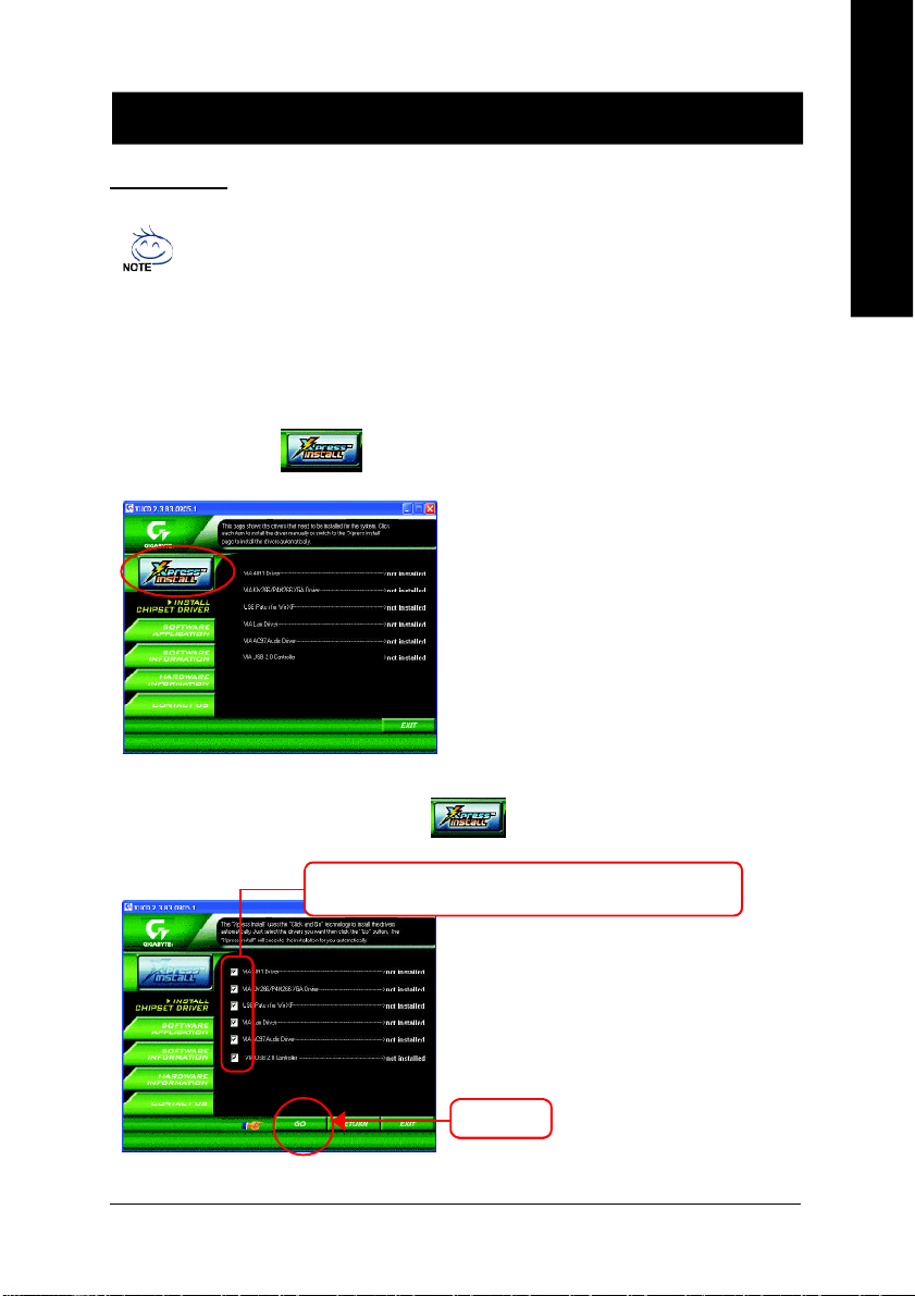
Install Drivers
Pictures below are shown in Windows XP (CD ver. 2.3)
Insert the driver CD-title that came with your motherboard into your CD-ROM drive, the driver
CD-title will auto start and show the installation guide. If not, please double click the CD-ROM
device icon in "My computer", and execute the setup.exe.
INSTALL CHIPSET DRIVER
This page shows the drivers that need to be installed for the system. Click each item to install the driver
manually or switch to the to install the drivers automatically.
English
The "Xpress Install" uses the"Click and Go" technology to install the drivers automatically. Just select the
drivers you want then click the "GO" button. The will execute the installation for you by itself.
We recommend that you install all components in the list.
Massage: Some device drivers will restart your
system automatically. After restarting your system
the "Xpress Install" will continue to install other
drivers.
Click "GO".
- 33 -
Driver Installation
Page 34

English
Item Description
n VIA 4IN1 Driver
n VIA KM266/P4M266 VGA Driver
n USB Path for WinXP
n VIA Lan Driver *
n VIA AC97 Audio Driver
n VIA USB 2.0 Controller
Driver install finished!! you have to reboot system!!
For INF, AGP, IDE and DMA Driver.
For VIA KM266/P4M266 VGA driver.
This patch driver can help you to resolve the USB device wake up S3 hang up issue in XP.
For VIA LAN driver.
Audio driver for VIA AC97 codec chipset.
For VIA VT8233 (VT6203) / VIA VT8235 / VIA VT8237/ VIA VT8237R south bridge.
For USB2.0 driver support under Windows XP operating system, please use Windows Service
Pack. After install Windows Service Pack, it will show a question mark "?" in "Universal Serial
Bus controller" under "Device Manager". Please remove the question mark and restart the
system (System will auto-detect the right USB2.0 driver).
"*" For 8VM533M-RZ only.
- 34 -8VM533M-RZ Series Motherboard
Page 35

Contact Us
English
— Taiwan (Headquarters)
GIGA-BYTE TECHNOLOGY CO., LTD.
Address: No.6, Bau Chiang Road, Hsin-Tien, Taipei Hsien,
Taiwan
TEL: +886 (2) 8912-4888
FAX: +886 (2) 8912-4003
Tech. Support :
http://tw.giga-byte.com/TechSupport/ServiceCenter.htm
Non-Tech. Support (Sales/Marketing) :
http://ggts.gigabyte.com.tw/nontech.asp
WEB address (English): http://www.gigabyte.com.tw
WEB address (Chinese): http://chinese.giga-byte.com
— U.S.A.
G.B.T. INC.
Address: 17358 Railroad St, City of Industry, CA 91748.
TEL: +1 (626) 854-9338
FAX: +1 (626) 854-9339
Tech. Support :
http://www.giga-byte.com/TechSupport/ServiceCenter.htm
Non-Tech. Support (Sales/Marketing) :
http://ggts.gigabyte.com.tw/nontech.asp
WEB address : http://www.giga-byte.com
— Germany
G.B.T. TECHNOLOGY TRADING GMBH
Address: Friedrich-Ebert-Damm 112 22047 Hamburg
TEL: +49-40-2533040 (Sales)
+49-1803-428468 (Tech.)
FAX: +49-40-25492343 (Sales)
+49-1803-428329 (Tech.)
Tech. Support :
http://de.giga-byte.com/TechSupport/ServiceCenter.htm
Non-Tech. Support (Sales/Marketing) :
http://ggts.gigabyte.com.tw/nontech.asp
WEB address : http://www.gigabyte.de
— Japan
NIPPON GIGA-BYTE CORPORATION
WEB address : http://www.gigabyte.co.jp
— Singapore
GIGA-BYTE SINGAPORE PTE. LTD.
Tech. Support :
http://tw.giga-byte.com/TechSupport/ServiceCenter.htm
Non-Tech. Support (Sales/Marketing) :
http://ggts.gigabyte.com.tw/nontech.asp
— U.K.
G.B.T. TECH. CO., LTD.
Address: GUnit 13 Avant Business Centre 3 Third Avenue, Denbigh
West Bletchley Milton Keynes, MK1 1DR, UK, England
TEL: +44-1908-362700
FAX: +44-1908-362709
Tech. Support :
http://uk.giga-byte.com/TechSupport/ServiceCenter.htm
Non-Tech. Support (Sales/Marketing) :
http://ggts.gigabyte.com.tw/nontech.asp
WEB address : http://uk.giga-byte.com
— The Netherlands
GIGA-BYTE TECHNOLOGY B.V.
TEL: +31 40 290 2088
NL Tech.Support: 0900-GIGABYTE (0900-44422983)
BE Tech.Support: 0900-84034
FAX: +31 40 290 2089
Tech. Support :
http://nz.giga-byte.com/TechSupport/ServiceCenter.htm
Non-Tech. Support (Sales/Marketing) :
http://ggts.gigabyte.com.tw/nontech.asp
WEB address : http://www.giga-byte.nl
- 35 -
Contact Us
Page 36

— China
NINGBO G.B.T. TECH. TRADING CO., LTD.
Tech. Support :
http://cn.giga-byte.com/TechSupport/ServiceCenter.htm
English
Non-Tech. Support (Sales/Marketing) :
http://ggts.gigabyte.com.tw/nontech.asp
WEB address : http://www.gigabyte.com.cn
Shanghai
TEL: +86-021-63410999
FAX: +86-021-63410100
Beijing
TEL: +86-010-82886651
FAX: +86-010-82888013
Wuhan
TEL: +86-027-87851061
FAX: +86-027-87851330
GuangZhou
TEL: +86-020-87586074
FAX: +86-020-85517843
Chengdu
TEL: +86-028-85236930
FAX: +86-028-85256822
Xian
TEL: +86-029-85531943
FAX: +86-029-85539821
Shenyang
TEL: +86-024-23960918
FAX: +86-024-23960918-809
— Australia
GIGABYTE TECHNOLOGY PTY. LTD.
Address: 3/6 Garden Road, Clayton, VIC 3168 Australia
TEL: +61 3 85616288
FAX: +61 3 85616222
Tech. Support :
http://www.giga-byte.com.au/TechSupport/ServiceCenter.htm
Non-Tech. Support (Sales/Marketing) :
http://ggts.gigabyte.com.tw/nontech.asp
WEB address : http://www.giga-byte.com.au
— France
GIGABYTE TECHNOLOGY FRANCES S.A.R.L.
Tech. Support :
http://tw.giga-byte.com/TechSupport/ServiceCenter.htm
Non-Tech. Support (Sales/Marketing) :
http://ggts.gigabyte.com.tw/nontech.asp
WEB address : http://www.gigabyte.fr
— Russia
Moscow Representative Office Of Giga-Byte Technology Co.,
Ltd.
Tech. Support :
http://tw.giga-byte.com/TechSupport/ServiceCenter.htm
Non-Tech. Support (Sales/Marketing) :
http://ggts.gigabyte.com.tw/nontech.asp
WEB address : http://www.gigabyte.ru
— Poland
Representative Office Of Giga-Byte Technology Co., Ltd.
POLAND
Tech. Support :
http://tw.giga-byte.com/TechSupport/ServiceCenter.htm
Non-Tech. Support (Sales/Marketing) :
http://ggts.gigabyte.com.tw/nontech.asp
WEB address : http://www.gigabyte.pl
- 36 -8VM533M-RZ Series Motherboard
 Loading...