

Page 1

8S651M-RZ /
8S651M-RZ-C
Intel Pentium® 4 Processor Motherboard
User's Manual
Rev. 1001
12ME-8S651MRZ-1001
Copy ri ght
© 2003 GIGABYTE TECHNOLOGY CO., LTD
Copyright by GIGA-BYTE TECHNOLOGY CO., LTD. ("GBT"). No part of this manual may be reproduced or transmitted in any from
without the expressed, written permission of GBT.
Tra demar ks
Third-party brands and names are the property of their respective owners.
Not ice
Please do not remove any labels on motherboard, this may void the warranty of this motherboard.
Due to rapid change in technology, some of the specifications might be out of date before publication of this booklet.
The author assumes no responsibility for any errors or omissions that may appear in this docum ent nor does the author make a
com mitment to update the information contained herein.
Page 2
Feb. 20, 2004
Mother Board
8S651M-RZ
Feb. 20 ,2004
Motherboard
8S651M-RZ
Page 3

Preparing Your Computer
Computer motherboards and expansion cards contain very delicate Integrated Circuit (IC) chips. To
protect them against damage from static electricity, you should follow some precautions whenever you
work on your computer.
1. Unplug your computer when working on the inside.
2. Use a grounded wrist strap before handling computer components. If you do not have one,
touch both of your hands to a safely grounded object or to a metal object, such as the power
supply case.
3. Hold components by the edges and try not touch the IC chips, leads or connectors, or other
components.
4. Place components on a grounded antistatic pad or on the bag that came with the components
whenever the components are separated from the system.
5. Ensure that the ATX power supply is switched off before you plug in or remove the ATX power
connector on the motherboard.
Installing the motherboard to the chassis
If the motherboard has mounting holes, but they don't line up with the holes on the base and there
are no slots to attach the spacers, do not become alarmed you can still attach the spacers to the
mounting holes. Just cut the bottom portion of the spacers (the spacer may be a little hard to cut off, so
be careful of your hands). In this way you can still attach the motherboard to the base without worrying
about short circuits. Sometimes you may need to use the plastic springs to isolate the screw from the
motherboard PCB surface, because the circuit wire may be near by the hole. Be careful, don't let the
screw contact any printed circuit write or parts on the PCB that are near the fixing hole, otherwise it
may damage the board or cause board malfunctioning.
Page 4

Table of Content
English
Chapter 1 Introduction ................................................................................................5
Chapter 2 BIOS Setup .............................................................................................. 21
Features Summary..............................................................................................................................5
8S651M-RZ Series Motherboard Layout ............................................................................................7
Block Diagram ..................................................................................................................................... 8
Hardware Installation Process ............................................................................................................ 9
Step 1: Install the Central Processing Unit (CPU).............................................................................9
Step 1-1: CPU Installation .........................................................................................................10
Step 1-2: CPU Cooling Fan Installation .................................................................................... 10
Step 2: Install memory modules ....................................................................................................... 11
Step 3: Install expansion cards ......................................................................................................... 12
Step 4: Install I/O Peripherals Cables .............................................................................................. 12
Step 4-1: I/O Back Panel Introduction ....................................................................................... 12
Step 4-2: Connectors Introduction .............................................................................................. 13
The Main Menu (For example: BIOS Ver. : E4) ............................................................................. 21
Standard CMOS Features ................................................................................................................ 23
Advanced BIOS Features ................................................................................................................25
Integrated Peripherals .......................................................................................................................26
Power Management Setup ................................................................................................................28
PnP/PCI Configurations .................................................................................................................... 30
PCI Health Status .............................................................................................................................31
Frequency/Voltage Control ................................................................................................................ 32
Top Performance ................................................................................................................................33
Load Fail-Safe Defaults ...................................................................................................................... 33
Load Optimized Defaults .................................................................................................................... 34
Set Supervisor/User Password ....................................................................................................... 34
Save & Exit Setup ............................................................................................................................35
Exit Without Saving ...........................................................................................................................35
Chapter 3 Driver Installation ...................................................................................... 36
8S651M-RZ Series M otherboard
- 4 -
Page 5

English
Chapter 1 Introduction
Features Summary
CP U — Socket 478 for Intel® M icro FC-PGA 2 Pentium® 4 proc essor
— Support Intel® Pentium® 4 (Northwood, 0.13 m) processor
— Intel Pentium®4 400 /533 M Hz FSB
— 2nd cache depen ds on C PU
Chip set — North Br idge:Si S 651
— South Bridge :SiS 962L M uTIOL Me dia I/O
Me mo ry — 2 184- pin DDR so ckets
— Supports DDR200/DDR2 66/DDR333
— Supports up to 2 un-buffer Double-sided DIMM DDR200/266
/333
— Suppo rts up to 2GB (M ax)
— Suppo rts only 2 .5V DDR DIM M
Slots — 1 Un ivers al AGP s lot ( 2X/4 X) de vice support
— 3 PCI slot sup ports 33M Hz & PCI 2.2 compliant
On-Board IDE — 2 IDE bus m aster (UDMA33/ATA66/ATA100/ATA133) IDE
ports for u p to 4 ATAPI devic es
— Supports PIO m ode3,4 (UDM A 33/ATA66/ATA100/ATA133)
IDE & ATAPI CD-R OM
On-Bo ard F loppy — Floppy port supports 2 FDD with 360K, 720K,1.2M, 1.44M and 2.88M bytes
On-Board P eripherals — 1 Par allel p ort sup ports Norm al/EPP/ECP mode
— 1 Seri al port (CO MA), 1 V GA port,COM B on board
— 6 x USB 2. 0/1. 1 (2 x R ear, 4 xFr ont by c able )
— 1 Front Audio Connector
— 1 IrDA connector for IR
— PS/2 Keyboa rd interface and PS/ 2 Mous e interface
On-Boar d VGA — Build in S iS651 C hipset
On-B oard L AN * — Build in RT L8201 Chips et
On-Board Sound — Realtek ALC655 CODEC
— Line Out / 2 front speaker
— Line In / 2 rea r spea ker( by s /w s witch)
— M ic In / c enter & subwo ofer( by s /w switch)
— SPDIF Ou t /SPD IF In
— CD_In / Game Port
BIOS — Lice nsed Award BIOS
— Supports Q-Flash
I/O Control — W83697HF
“*” F or 8 S65 1M -RZ only.
Introduction- 5 -
Page 6

Hardware M onitor — CPU/ System Fan Revolution detect
English
Additional F eatures — PS/ 2 Keyb oar d po wer on by pas sword
Form Factor — 24.4 cm x 21.5 cm M icro ATX siz e form factor, 4 layers PCB.
— CPU/ System Fan Control
— CPU O verheat Warni ng
— System Voltage Detect
— PS/2 Mo use power on
— STR(Su spend-To-RAM )
— AC R ec ove ry
— USB KB/M ouse wake up from S3
— Supports Eas yTune 4
— Supports @B IOS
Please set the CPU host frequen cy i n accord ance with your p rocessor 's speci fications.
We don't recom men d you to set the system b us frequency over the CPU's specification
because these specific bus frequenc ies are not the standard specifications for CPU,
chipset and most of the peripherals. Whether your system can run under these specific
bus frequenci es pro perly will depe nd on your hardware c onfigurations, i ncluding C PU,
Chipse ts, Mem ory, Cards… .etc.
8S651M-RZ Series M otherboard
- 6 -
Page 7
English
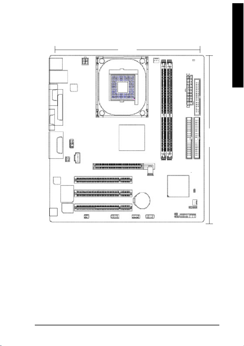
8S651M-RZ Series Motherboard Layout
21.5 c m
KB_MS
USB_LAN
COMA
VGA
LINE_OUTMIC_IN
LINE_IN
CODEC
-C
*
RT L82 0 1
LPT
F_AU DIO
GAME
SUR_C EN
W83697HF
BIOS
CD _IN
ATX_12 V
*
SPDIF_IO
SOC KET478
COMB
SiS 6 51
PCI1
PCI2
PCI3
F_U SB2
AGP
BAT
F_U SB1
CPU_FAN
8S651M-RZ
DDR2
DDR1
SiS 962L
SYS _FAN
CLR_ CM OS
PWR_ LED
DIMM _LED
ATX
IDE2
IR
F_PANEL
FD D
24.4 cm
IDE1
CI
“ * ” For 8S651M-RZ only.
Introduction- 7 -
Page 8
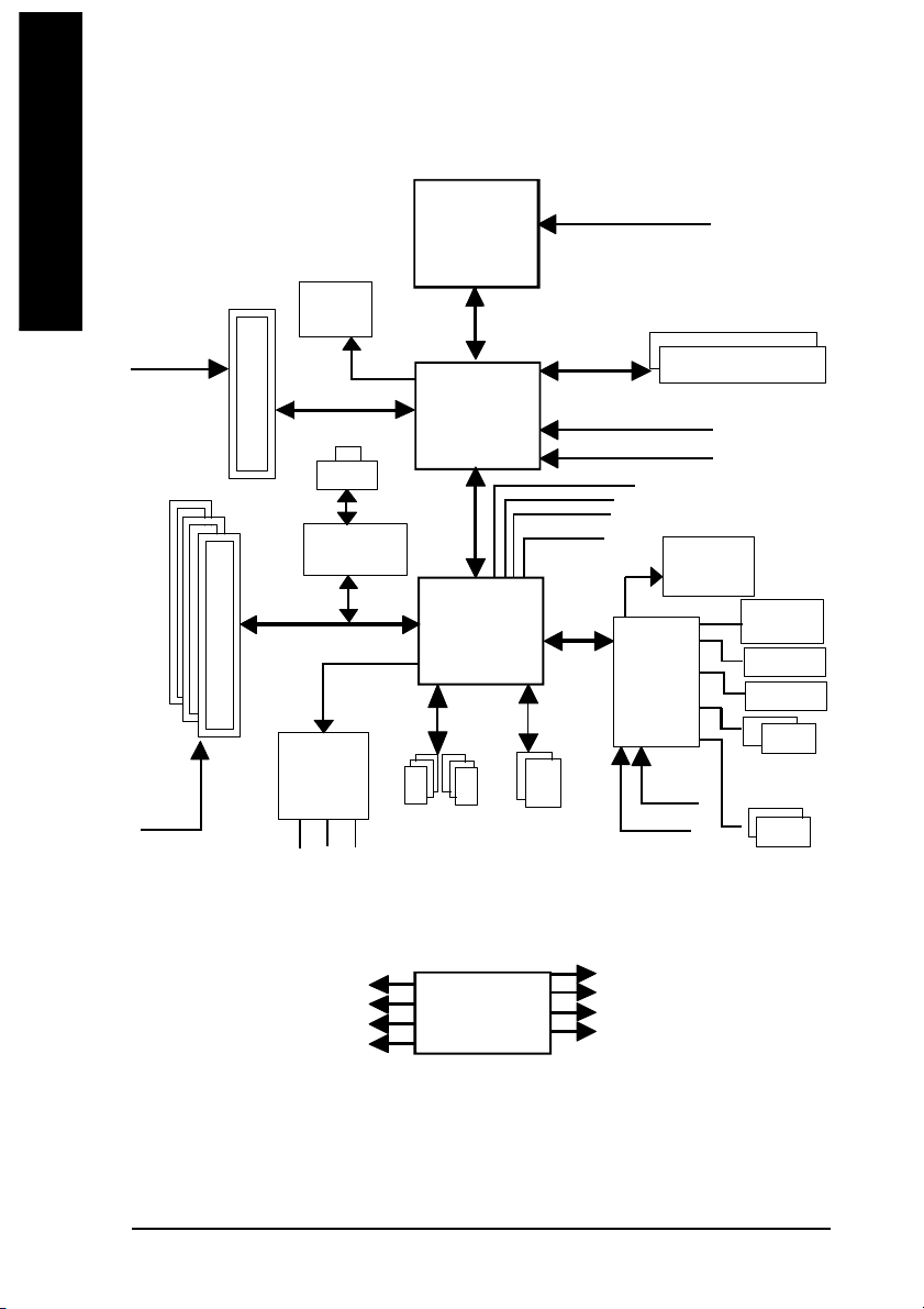
Block Diagram
English
AGPC LK
(66MHz)
PCICL K
(33MHz)
3 P CI
AGP 2X/ 4X
VGA Port
RJ45
RTL8201
AC97 Li nk
AC97
CODE C
MIC
LINE-IN
*
*
LINE-OUT
Pentium 4
Socket 478
CP U
SiS 651
SiS 962L
6 U SB
Ports
CPUCLK+/- (1 00/133 MHz)
System Bus
400/533 MHz
200/266/333MHz
ZCLK (66M Hz)
HCLK+/- (100/133 M Hz)
66 MHz
48 MHz
LPC BUS
ATA33/66/100/133
IDE Channels
33 MHz
14.318 MHz
W83697HF
24 MHz
33 MHz
DDR
BIOS
Game Port
Flop py
LPT Port
PS/2
KB/M ouse
COM
Por ts
PCICLK (33M Hz)
USBCLK (48 MHz)
14.318 MHz
33 MHz
“ * ” F or 8S6 51M -RZ only .
8S651M-RZ Series M otherboard
CLK GEN
- 8 -
ZCLK (66M Hz)
CPUCLK+/- (1 00/133 MHz)
AGPCLK (66M Hz)
HCLK+/- (100/133 M Hz)
Page 9
English
Hardware Installation Process
To s et up your co mp uter, you mus t co mpl ete the following steps:
Step 1- Install the Central P rocess ing Unit (CP U)
Step 2- Install mem ory modules
Step 3- Install e xpansi on car ds
Step 4- Install I/O Pe riphera ls cabl es
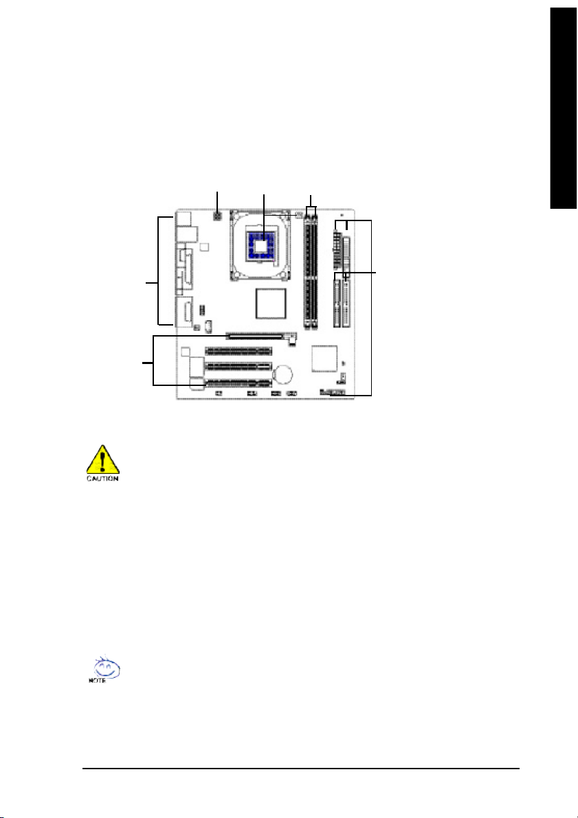
Step 4
Step 1
Step 2
Step 4
Step 3
Step 1: Install the Central Processing Unit (CPU)
Before i nstalling the p rocess or, adh ere to the following warning:
1. Pleas e m ake sure the CPU type i s supp orted by the m otherboard.
2. The p rocess or will over heat without the he atsink an d/or fan, resul ting i n perm anent
irreparable dam age.
3. If you do not match the CP U socke t Pin 1 and CPU cut edge well, it will caus e im proper
installation. Please change the in sert orientation.
4. Apply therma l grea se between the proce ssor a nd cooling fan.
5. Never run the pro cessor without the he atsink p roperl y and firmly attached . Perm anent
dam age will resul t.
6. Pleas e set the CPU hos t frequency in accorda nce with your pr ocessor 's spe cifications.
We don' t recomm end you to set the system bus frequency over the CPU's specification
becau se these specific bus frequenc ies are no t the standard specifica tions for CPU,
chipset and mos t of the periphe rals. Wh ether your s ystem ca n ru n under these specific
bus freq uencies pr operly will depe nd on your hardware configura tions, includ ing CP U,
Me mo ry, Card s… etc.
HT fu nctio nality re quir ement c ontent :
Ena bl ing the fun ctio nal ity of H yp er- Thr ea din g Techn ol ogy for your c om puter system
requir es all o f the following pla tform com ponents:
- CP U: An Intel® Pen tium 4 Proce ssor with HT Techno logy
- Chi pset: An Intel® Chi pset that suppo rts H T Technolo gy
- BIOS: A BIOS that su pports HT Technol ogy an d has it enabled
- OS: An op eration s ystem that has optim izations for HT Techn ology
Step 4
- 9 - Hardware Installation Proc ess
Page 10
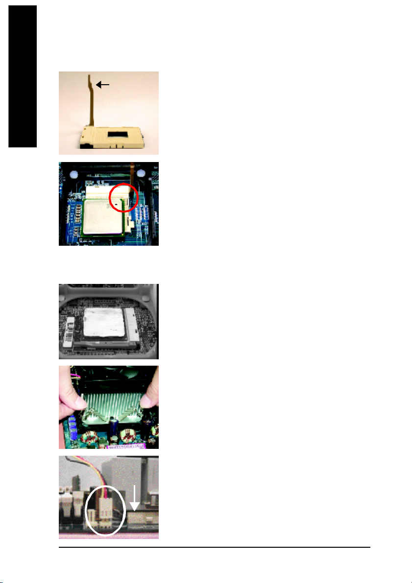
Step 1-1: CPU Installation
English
Step 1-2: CPU Cooling Fan Installation
Socket
Actuation
Lever
Figure 1.
Pull the r od to the 9 0-degree directly.
Figure 2.
Locate Pin 1 in the s ocket an d loo k for a (golde n) cu t edge on the
CPU up per corn er. Insert the C PU into the soc ket. (Do not force the
CPU i nto the sock et.) Then mov e the s ock et l eve r to the locke d
position while ho lding pressure on the c enter of the CPU.
Figure 1.
Apply the therm al tape(or grease) to provide better heat conduction
between you r CP U a nd c oolin g fan.
8S651M-RZ Series M otherboard
Figure 2.
Fasten the coo ling fan suppor ting-base o nto the CPU socket on the
motherboard.
Figure 3.
Ma ke sur e the CPU fan is plugg ed to the CPU fan co nnector, than
install c omp lete.
- 10 -
Page 11
English
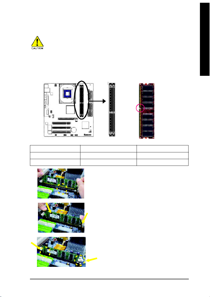
Step 2: Install memory modules
Before i nstalling the m emory modules, adhere to the following warning:
1. When D IMM LED is ON , do no t install / rem ove D IMM from socke t.
2. Plea se no te that the DIMM mo dule can onl y fit i n on e d irectio n due to the o ne no tch.
Wrong orientation will cause impr oper ins tallation. Plea se chang e the i nsert orientation.
The mother boar d ha s 2 du al inl ine mem ory m odul e (DIM M) s ocke ts. Th e BIOS wil l autom atica lly
detects me mo ry type and siz e. To instal l the mem ory mo dule , just p ush it ve rtical ly into the DIMM
socket. The DIM M m odule can only fit in one direction due to the notch. Mem ory size c an vary between
soc ke ts.
Notch
DDR
Support Unbuffered DDR DIMM Sizes type:
64 Mbit (2Mx8x4 banks) 64 Mbit (1Mx16x4 banks) 128 Mbit(4Mx8x4 banks)
128 Mbit(2Mx16x4 banks) 256 Mbit(8Mx8x4 banks) 256 Mbit(4Mx16x4 banks)
512 Mbit(16Mx8x4 banks) 512 Mbit(8Mx16x4 banks)
1. The DIMM socket has a notch, so the DIMM
me mor y mo dule can o nly fit in one d irection.
2. Inse rt the D IMM m emo ry m odul e vertical ly in to
the DIM M soc ket. The n pus h i t down.
3. Close the pl astic c lip at both e dges of the DIMM
sockets to lo ck the DIMM m odule.
Reve rse the installation steps when yo u wish to
rem ove the DIMM modu le.
- 11 - Hardware Installation Proc ess
Page 12
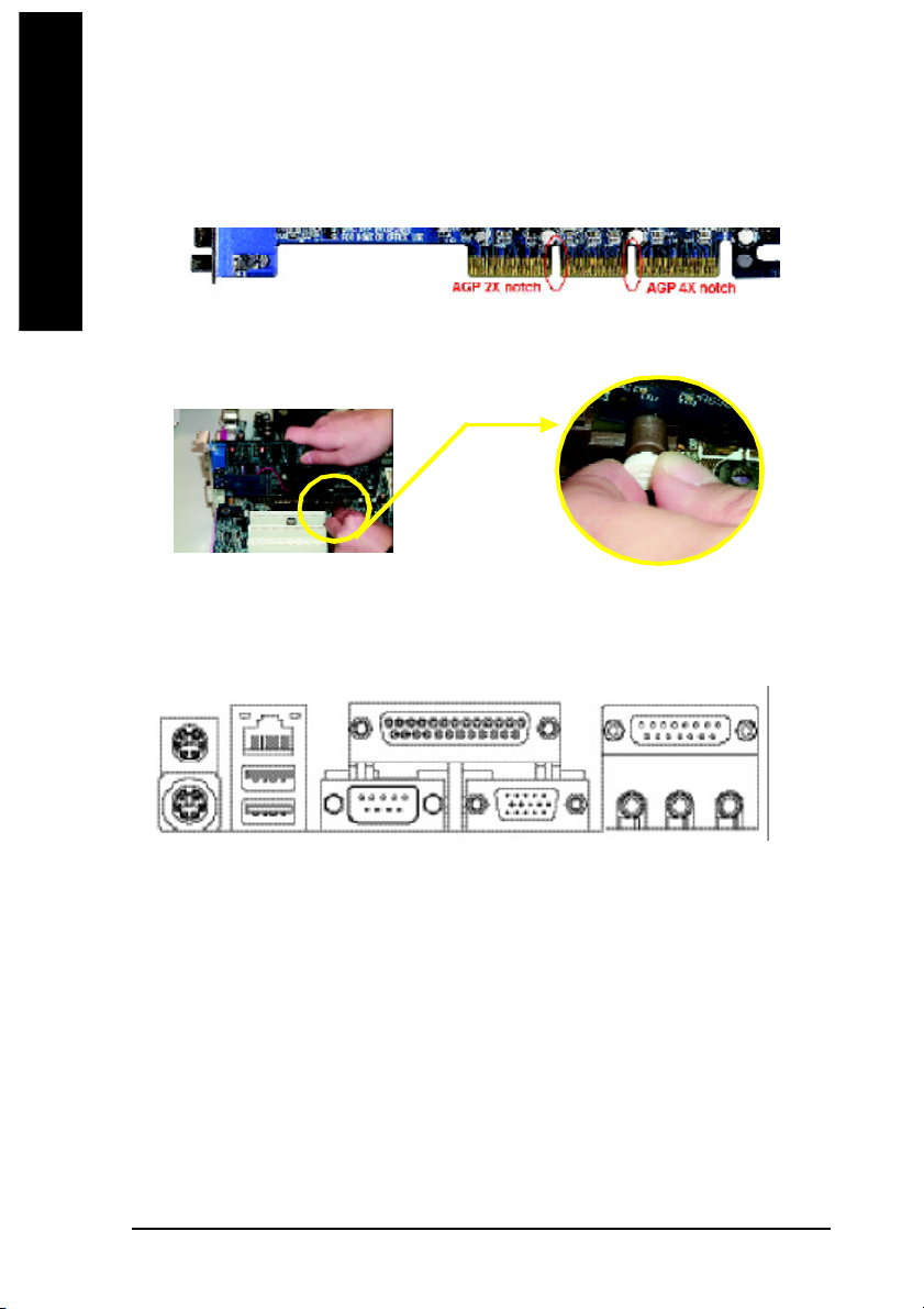
Step 3: Install expansion cards
1. Read the related expansion car d's instruction document before install the expans ion card into
English
2. Please mak e sure y our A GP card is AG P 4 X/8X (1.5V ).
3. Please carefully pull out the smal l white- dra wable bar at the e nd of the AGP slot when you try to
Step 4: Install I/O Peripherals Cables
Step 4-1: I/O Back Panel Introduction
the computer.
install/ Uninstall the AGP card. Ple ase align the AGP card to the onb oard AGP slot and press firm ly
down on the slot .M ake sure your AGP card is locked by the sm all white- drawable bar.
AGP Card
u
v *
x
{
w
y z
}
|
~
u PS/2 Keyboard and PS/2 Mouse connector
This connec tor supp orts s tandard P S/2 ke yboard and PS/2 m ouse.
v LAN port*
LAN is fast Ethernet with 10/10 0M bps sp eed.
w USB port
Before yo u conne ct your device( s) into US B co nnector(s) , pleas e ma ke sure you r devic e(s) su ch
as USB keyboard , mo use, scan ner, zip , speake r...etc. Have a s tandard USB i nterface. Also m ake
sure y our OS suppo rts USB con troller. If your OS doe s not suppo rt USB c ontroller, please c ontact
OS ven dor for possib le patch or driver upgrad e. F or m ore inform ation please contact your OS or
dev ice( s) ven dors .
x Parallel port (LPT)
Devic e like printer can b e conne cted to Pa rallel port.
y Serial port (COMA)
Mo use and mode m e tc. can be conn ected to Serial port.
"*" For 8S651M-RZ only.
8S651M-RZ Series M otherboard
- 12 -
Page 13

English
z VGA port
Mo nitor can b e conne cted to VGA port.
{ Game/MIDI port
This conne ctor s uppor ts joystick, M IDI keyboard and other relate audio devices.
| Line Out jack
Connec t the stereo speak ers or earphone to this c onnector.
} Line In jack
Devi ces l ike CD-R OM , walkm an etc. can be connect to Line In jack.
~ MIC In jack
Mi crophon e can be c onnect to M IC In jac k.
After installa tion o f the audio d river, yo u are able to use 2/4/6- channe l audio feature by software
selection. You c an connec t "Front spea ker" to "Line Out" jack, C onnect "Rear speak er" to "Line In"
jack and conn ect "Cen ter/Subwoofer" to "M IC In" jack.
Step 4-2: Connectors Introduction
31 7
2
6
13
11
12
14
10 817
16
9
5
19
18
4
15
1) ATX_12V 11) F_AUDIO
2) ATX 12) SUR_CEN
3) CPU_FAN 13) CD_IN
4) SYS_FAN 14) SPDIF_IO
5) IDE1/IDE2 15) I R
6) FDD 16) F_USB1/F_USB2
7) DIMM_LED 17) COMB
8) F_PANEL 18) C I
9) PWR_LED 19) CLR_CMOS
10) BAT
- 13 - Hardware Installation Proc ess
Page 14

1) ATX_12V (+12V Power Connector)
This connector (ATX _12V) supplies the CPU operation voltage (Vco re).
If this " ATX_ 12V connec tor" is not conne cted, system cannot boot.
English
2) ATX (ATX Power)
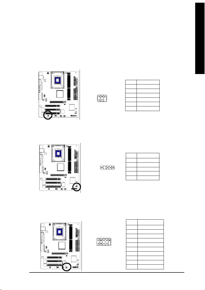
3) CPU_FAN (CPU FAN Connector)
Pin No. Definition
3
4
2
1
1 GND
2 GND
3 +12V
4 +12V
AC power cord should only be connected to your p ower supply unit after ATX power cable and other
related devices are firmly conn ected to the mainboard.
Pin No . De finition
1 1
2 0
1
1 3.3V
2 3.3V
3 GND
4 VCC
5 GND
6 VCC
7 GND
8 Powe r Good
1 0
9 5V SB (stand by +5V)
10 +12V
Pin No . De finition
11 3.3V
12 -12V
13 GND
14 PS_O N(soft on/off)
15 GND
16 GND
17 GND
18 -5V
19 VCC
20 VCC
Please note, a proper installation of the CPU coo ler is essential to prevent the CPU from run ning
under abnorm al condition or dam aged by overheating.The C PU fan connector supports M ax.
current up to 600 mA.
8S651M-RZ Series M otherboard
1
- 14 -
Pin No. Definition
1 GND
2 +12V
3 Sense
Page 15

English
4) SYS_FAN (System FAN Connector)
This c onnector allows yo u to li nk with the cooli ng fan on the system c ase to lower the system
temperature.
Pin No. Definition
1
1 GND
2 +12V
3 Sense
5) IDE1/ IDE2(IDE1/IDE2 Connector)
Please conn ect first hard disk to IDE1 and connect CDR OM to IDE2.
The red stripe of the ribbon cable m ust be the sam e side with the Pin1.
4 0
2
3 9
1
IDE1IDE2
6) FDD (Floppy Connector)
Please conne ct the floppy drive ribbon ca bles to FDD. It supports 360K, 720K,1.2M ,1.44M and
2.88M bytes floppy disk types.
The red stripe of the ribbon cable m ust be the sam e side with the Pin1.
3 3
3 4
1
2
- 15 - Hardware Installation Proc ess
Page 16

7) DIMM_LED
English
8) F_PANEL (2x10 pins connector)
Do not remove me mory m odules while DIMM LED is on. It mi ght cause short or other unexpected
dama ges due to the 2.5V stand by voltage. Re move m emory m odules only when AC Power cord
is dis connected.
+ -
Please conn ect the power LED, PC peaker, reset switch and power switch etc of your chassis front
panel to the F_PANEL connector accordi ng to the pin assign ment above.
Mes sa ge LED /P ow er /
Sleep L ED
MPD MPD +
IDE H ard Disk
Acti ve LED
HD+
HD-
HD (IDE Hard Disk Active LED) Pin 1: LED anode(+)
Pin 2: LED cathode(-)
SPK (Speaker Connector) Pin 1: VCC(+)
Pin 2- Pin 3: NC
Pin 4: Data(-)
RST (Reset Switch) Open: Normal Operation
Close: Reset Hardware System
PW (Soft Power Connector) Open: Normal Operation
Close: Power On/Off
MPD(Message LED/Power/ Pin 1: LED anode(+)
Sleep LED) Pin 2: LED cathode(-)
NC NC
Soft P ower
Connec tor
1
2
1
1
Reset S witch
PW+
1
RS T-
RST +
PW-
Speaker
Connector
SP K -
SP K+
1
1
NC
20
19
8S651M-RZ Series M otherboard
- 16 -
Page 17

English
9 ) PWR_LED
PWR_LED is con nect with the system power indicator to indic ate whether the system is o n/off. It will
blink when the system enters suspend mode. If you use dual color LED , po wer LED will turn to
another color.
Pin No. Definition
1
1 MPD+
2 MPD3 MPD-
10) BAT (Battery)
+
CAUTION
Da nge r of e xp los io n if batte ry i s inco rr ectl y
replace d.
Repl ace on ly with the s am e or equivale nt type
recom men ded by the m anufacturer.
Di sp ose of us ed b atte ri es a cc or di ng to the
ma nufacturer's i nstructions.
If you want to era se CM OS. ..
1. Turn OFF the com puter and unplug the power cord.
2. R em ove the b attery, wait for 30 sec ond.
3. R e-ins tall the battery.
4. Pl ug the power cor d and turn O N the com puter.
- 17 - Hardware Installation Proc ess
Page 18

11) F_AUDIO (F_AUDIO Connector)
English
12) SUR_CEN
If you want to use Front Audio connector, you m ust remove 5-6, 9-10 Jum per. In order to utilize the
front audio header, your chassis must have front audio connector. Also pleas e make sure the pin
assigment on the cable is the same as the pin assigment on the MB header. To find out if the chassis
you are buying su pport front audio connector, plea se contact your deal er.Pleas e note, you can
have the alternative of using front audio connector or of using rear audio connector to play sou nd.
Pin No. Definition
1 2
1 09
1 MIC
2 GND
3 REF
4 POWER
5 FrontAudio(R)
6 RearAudio(R)
7 Reserved
8 No Pin
9 FrontAudio (L)
10 RearAudio(L)
Please co ntact your neare st dealer for optional SUR_CEN cab le.
Pin No. Definition
1 SUR OUTL
1
5 6
2
2 SUR OUTR
3 GND
4 No Pin
5 CENTER_OUT
6 BASS_OUT
13) CD_IN
Connect CD-ROM o r DVD-ROM a udio out to the connector.
8S651M-RZ Series M otherboard
- 18 -
1
Pin No. Definition
1 CD-L
2 GND
3 GND
4 CD_R
Page 19
English
14) SPDIF_IO (SPDIF In/Out)
The SP DIF output is capable of providi ng digi tal aud io to external speake rs o r com press ed AC3
data to an ex ternal Dol by Dig ital Dec oder. Us e this feature o nly when y our ster eo system has
digital input function. Use S PDIF IN feature only when you r d evice has digital output func tion.
Be ca reful with the po larity of the SP DIF_IO con nector. Ch eck the pi n a ssignm ent carefully while
you c onnec t the SP DIF_IO cabl e, incorr ect conn ection b etween the cable and conn ector will
mak e the device unable to work or even dam age it. For o ptional S PDIF_IO cable, ple ase contact
your local de aler.
Pin No. Definition
1 VCC
5
6 2
1
2 No Pin
3 SPDIF
4 SPDIFI
5 GND
6 GND
15) IR
Mak e sure the pin 1 on the IR device is a ling with pin one the connector. To enable the IR function
on the board, you a re required to purchase an option IR module. Be careful with the polarity of the
IR conne ctor. For o ptional IR cab le, pl ease c ontact your lo cal de aler.
Pin No. Definition
1 VCC
1
2 No Pin
3 IR Data Input
4 GND
5 IR Data Output
16) F_ USB1 / F_USB2 (Front USB Connector)
Be careful with the polari ty of the F_USB c onnector. Check the pin assi gnment care fully while you
connect the F_U SB cable, i ncorrect co nnection between the cable a nd connector will make the
device u nable to work or eve n dam age it. Fo r optional F_USB cabl e, please contact your lo cal
dealer.
2 10
9
1
- 19 - Hardware Installation Proc ess
Pin No. Definition
1 Power
2 Power
3 USB DX4 USB Dy5 USB DX+
6 USB Dy+
7 GND
8 GND
9 No Pin
10 NC
Page 20

17) COMB (COM B Connector)
English
18) CI (CASE OPEN)
Be car eful with the polar ity of the COMB connec tor. Check the pin assignm ent while you connect
the COM B cab le. Pleas e contact you r neare st dealer for op tional CO MB c able.
Pin No. Definition
1 NDCDB-
1 02
1 9
2 NSINB
3 NSOUTB
4 NDTRB5 GND
6 NDSRB7 NRTSB8 NCTSB9 NRIB10 No Pin
This 2 pin co nnector allows your system to enable or disable the "case o pen" item in BIOS if the
system case begin rem ove.
1
Pin No. Definition
1 Signal
2 GND
19) CLR_CMOS (Clear CMOS)
You ma y clea r the C MOS data to its default values by this j umpe r. To c lear C MOS, tempo rarily
shor 1- 2 pin. D efault doesn't includ e the "Shunter" to preven t from im proper u se this jum per.
1
Open: Nor mal
1
Clos e: Cl ear CMOS
8S651M-RZ Series M otherboard
- 20 -
Page 21

Chapter 2 BIOS Setup
BIOS Se tup is an ov ervie w of the BIOS Setup Progr am. Th e prog ram that al lows use rs to mod ify the
basic system co nfiguration. This type of inform ation is stored in battery-backed CMOS RAM so that it
retains the Setup informa tion when the po wer is turned off.
ENTERING SETUP
Powering ON the com puter and pressing <Del> immediately will allow you to enter Setup. If you require
m o re ad v an c ed BIO S settings, please go to "Advanced BIO S" setting men u. To enter
Advan ced B IOS se tting me nu, p ress " Ctrl+F1" ke y on the BIOS scree n.
CONTROL KEYS
< >< >< >< > M ove to se lect item
<Enter> Select Item
<Esc > Ma in M enu - Q uit an d not save changes into CM OS Status Page S etup Me nu
and Option Page Setup M enu - Exit cur rent page and return to Ma in M enu
<+/P gUp> Increase the num eric value or make chang es
<-/PgDn> Decrea se the num eric value or make changes
<F1> General help, o nly for Status Pa ge Setup M enu and Option Page Setup M enu
<F2> Item Help
<F5> Restore the previous CM OS value from CMOS, only for Option Page Setup Menu
<F6> Load the file- safe de fault CMOS value from B IOS default table
<F7> Load the Op timized D efaults
<F8> Q-Fl ash utili ty
<F9> System Inform ation
<F10> Save all the CM OS ch anges , o nly for M ain M enu
Main Menu
The on -line d escription of the hig hlighted s etup function is disp layed a t the b ottom o f the s creen.
Status Page Setup Menu / Option Page Setup Menu
Press F1 to pop up a sm all h elp window that desc ribes the a ppropr iate key s to u se and the possib le
selec tions for the high lighted i tem. T o e xit the Help Windo w pres s <Esc >.
English
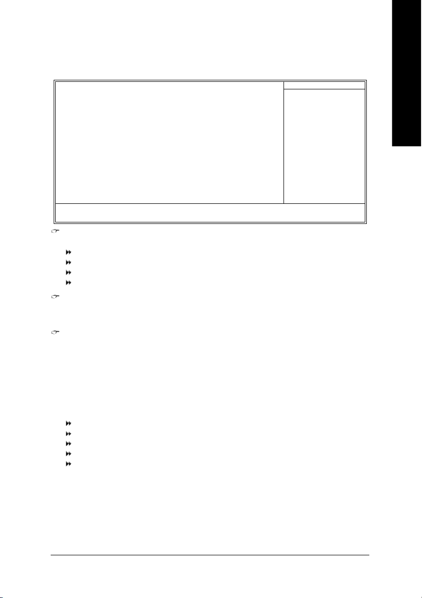
The Main Menu (For example: BIOS Ver. : E4)
Once you enter Award BIOS CM OS Setup U tility, the Ma in M enu ( as figure be low) will ap pear on the
scr een. T he M ain Menu allows you to select from eight setup functions and two exit choices. Use
arrow ke ys to s elect am ong the items and press <Enter> to a ccept or enter the s ub-m enu.
CMOS Setu p Utili ty-Co pyrig ht (C ) 198 4-200 4 Award Soft ware
} Standa rd CM OS Feat ures
} Advanc ed BI OS Feat ures
} Integr ated Per iphe rals
} Power Manag ement S etup
} PnP/PC I Co nfig urat ions
} PC Heal th Stat us
} Frequen cy/V oltag e C ontr ol
ESC: Qu it higf: Select Item
F8: Q-Fla sh F10: Save & Exit Set up
Time , Dat e, Har d Disk Type. ..
Top Perf orma nce
Load Fail -Safe D efaul ts
Load Opti mized D efaul ts
Set Super visor P asswo rd
Set U ser Pass word
Save & Exit S etup
Exit Witho ut Savi ng
- 21 - BIOS Setup
Page 22

If you can't find the setting you want, please press "Ctrl+F1" to search the advanced
option hidden.
English
• Standard CMOS Features
• Advanced BIOS Features
• Integrated Peripherals
• Power Management Setup
• PnP/PCI Configuration
• PC Health Status
• Frequency/Voltage Control
• Top Performance
• Load Fail-Safe Defaults
• Load Optimized Defaults
• Set Supervisor Password
• Set User Password
• Save & Exit Setup
• Exit Without Saving
This s etup page includes al l the item s in standard com patible BIOS.
This setup page i nclude s all the item s of Award specia l e nhance d features.
This se tup page incl udes all onbo ard perip herals.
This s etup page incl udes all the items of Gree n function features.
This setup pag e i nclude s all the configu rations of PCI & P nP ISA resou rces.
This setup p age is the System a uto detect Tem perature, voltage, fan, s peed.
This setup page is co ntrol CPU clock and freque ncy ra tio.
If you wis h to m axim ize the pe rforma nce o f your system , se t "Top Pe rform ance" as "Enab led".
Fail-Sa fe Defaults indicates the value of the sys tem param eters which the system would be in s afe
configuration.
Optim ized Defaults indi cates the value of the system p aram eters which the sys tem woul d b e in
best performa nce configuration.
Chan ge, s et, o r dis able password. It allows you to li mi t access to the system and Setup, or just
to Setup.
Chan ge, set, or d isab le pass word. It allo ws you to l im it ac cess to the sys tem.
Save CM OS val ue se ttings to CM OS an d exit se tup.
Aband on al l C MOS value chan ges an d e xit setup.
- 22 -8S651M-RZ Series M otherboard
Page 23
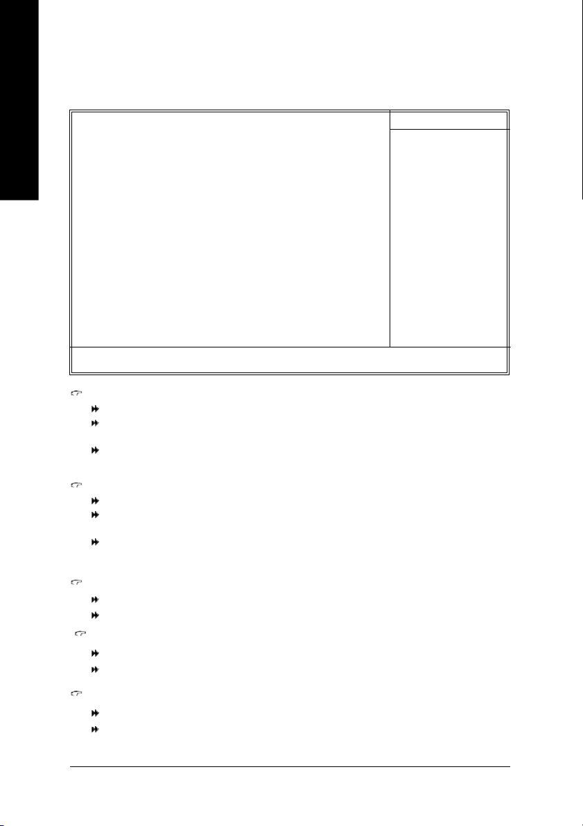
Standard CMOS Features
CMOS Setu p Utili ty-Co pyrig ht (C ) 198 4-200 4 Award Soft ware
Date (mm :dd: yy) Fri, Jan 9 2004
Time (hh :mm: ss) 22: 31:2 4
} IDE Pri mary Ma ster [No ne]
} IDE Pri mary Sla ve [No ne]
} IDE Sec ondary M aster [No ne]
} IDE Sec ondar y S lave [No ne]
Driv e A [1 .44M, 3.5 "]
Driv e B [ None ]
Flopp y 3 Mode Supo rt [Disab led]
Holt On [A ll, B ut Keybo ard]
Base Memo ry 640K
Exte nded Mem ory 127M
Tota l Me mory 128M
higf: Mov e Enter: Sele ct +/-/PU /PD: Val ue F10: Sa ve ESC: Exit F1 : Gen eral He lp
F5: Previo us Valu es F6: F ail-Sa ve Defau lt F7: Optim ized De faul ts
Date
The d ate form at is <week>, <month>, <day>, <year>.
Week The week, from Sun to Sat, d eterm ined by the BIOS and is displ ay on ly
Month The m onth, Jan . Th rough De c.
Day Th e day, from 1 to 31 ( or the max imu m al lowed in the m onth)
Year The year, from 1999 through 2098
Time
The tim es format in <hour> <minute> <second>. The time is calculated base on the 24-hour
mi litary-tim e clock. For example, 1 p.m. is 13:00:00.
IDE Primary Master, Slave / IDE Secondary Master, Slave
The c ategor y i dentifie s the typ es of har d di sk from drive C to F that has been installed in the
com puter. The re are two types: auto type, and ma nual type. Man ual type i s us er-definab le; Auto type
which will autom atical ly detect H DD type.
Note that the spec ifications of y our d rive m ust match with the drive table. The hard disk will not work
proper ly if you enter impr oper i nformation for this category.
If yo u se lect Use r Ty pe, related i nform ation will be as ked to e nter to the fol lowing i tems . En ter the
inform ation directly from the keyboar d and p ress <En ter>. Such information should be provided in the
docum entation form your har d disk vendor or the system manu facturer.
Cyli nder Num ber o f cyli nders
Head Num ber of hea ds
Precom p Write precomp
Landing Zone Landing zone
Sector Nu mbe r of se ctors
If a hard disk has no t been installe d, sel ect NONE a nd press <Enter>.
Stan dard CMOS Fe atur es
Item He lp
Menu Leve l}
Chan ge th e day, mont h,
year
<We ek>
Sun. to Sat.
<Mon th>
Jan. to Dec.
<Day>
1 to 31 (or maxim um
allow ed in th e mont h)
<Ye ar>
1999 to 2098
English
- 23 - BIOS Setup
Page 24

com puter.
English
Drive A / Drive B
The categor y iden tifies the types of flo ppy disk drive A or drive B that h as been ins talled in the
None No flo ppy drive i nstall ed
360K, 5. 25" 5.25 inc h PC-type stand ard dri ve; 360K by te cap acity.
1.2M , 5.25" 5. 25 i nch AT-typ e hig h-den sity driv e; 1. 2M by te capa city
(3.5 inch when 3 M ode is En abled ).
720K, 3 .5" 3.5 inch double-s ided drive ; 720 K b yte capa city
1.44M , 3.5" 3. 5 inc h doubl e-sid ed dri ve; 1 .44M byte ca pacity.
2.88M , 3.5" 3. 5 inc h doubl e-sid ed dri ve; 2 .88M byte ca pacity.
Floppy 3 Mode Support (for Japan Area)
Disabled No rma l Flo ppy D rive. (Default valu e)
Driv e A Driv e A is 3 m ode Floppy Driv e.
Driv e B Driv e B is 3 m ode Floppy Driv e.
Both Driv e A & B are 3 mod e Flopp y Dri ves.
Halt on
The c ategory determ ines whether the co mpu ter will s top if an error is de tected durin g p ower up.
No Erro rs The s ystem boot will not stop for any error that m ay be detected and y ou
will be pr omp ted.
All Err ors Wh enever the BIOS detects a non-fatal error the sy stem will b e stoppe d.
All, But K eyboa rd Th e sys tem boot will not s top for a keyboard error ; it will stop for al l other
errors. (Default value)
All, But Dis kette The system boot will not stop for a disk er ror; it will stop for all other errors.
All , Bu t D isk/ Key Th e system boot will not stop for a keyb oard or dis k error; it will stop for a ll
other errors.
Memory
The categor y is di splay -onl y whi ch is determ ined by POST (Power On Self Test) of the BIOS.
Base Memory
The POS T of the BIOS will d etermine the amo unt of base (or conv entional) m em ory ins talled
in the s ystem .
The v alue of the base me mor y i s typical ly 512K for s ystems with 512K m emory installed on
the motherboard, or 640K for systems with 640K or more mem ory installed on the motherboard.
Extended Memory
The B IOS de termin es how m uch extended m em ory i s pres ent durin g the POST.
This is the am ount of m em ory located above 1 M B i n the CPU 's m em ory addr ess m ap.
- 24 -8S651M-RZ Series M otherboard
Page 25

Advanced BIOS Features
CMOS Setu p Utili ty-Co pyrig ht (C ) 198 4-200 4 Award Soft ware
First Boo t Dev ice [Flopp y]
Second Boot Device [HDD- 0]
Third Boot Devi ce [CDRO M]
Boot Up Flop py Seek [D isable d]
Passw ord Che ck [S etup]
higf: Mov e Enter: Sele ct +/-/ PU/P D: V alue F1 0: Save ESC: Exit F1: Gener al Help
F5: Previo us Valu es F6: F ail-Sa ve Defau lt F7 : Op timiz ed Defa ults
First / Second / Third Boot Device
Flop py Se lect your boot device prio rity by Flopp y.
LS120 Select your boo t device priority by LS1 20.
HDD-0~3 Sel ect your boot device pri ority by HDD-0~3.
SCSI Select your bo ot device priority by SCSI.
CDROM Select yo ur boot device pr iority by CDROM.
ZIP Selec t your boot devic e p riority by ZIP.
USB-FDD Se lect your boot devic e pr iority by USB-FD D.
USB-ZIP Se lect your boot device prior ity by USB-ZIP.
USB-CDROM Select your boot dev ice priori ty by U SB-CDRO M.
USB-HDD Select your boot dev ice priority by USB-H DD.
LAN Select your boot device prio rity by LAN.
Disabled Sel ect your boot device pri ority by Disable d.
Adva nced BIOS Fe atur es
Item He lp
Menu Leve l}
Sele ct Bo ot Devi ce
pri orit y
[Fl oppy ]
Boot from fl oppy
[LS1 20]
Boot from L S120
[HDD -0]
Boot from Fi rst H DD
[HDD -1]
Boot from Sec ond H DD
English
Boot Up Floppy Seek
During P OST, BIOS will determine the floppy di sk dr ive installed is 40 or 8 0 tracks. 360K type is
40 tracks 720K, 1.2M and 1.44M are all 80 tracks.
Enabled BIOS searches for floppy disk drive to determine it is 40 or 80 tracks. Note
that BIOS can not tell from 720K, 1.2M or 1.44M drive type as they are
all 80track s.
Disabled BIOS will not sear ch for the type of floppy disk d rive by track num ber. No te
that there will not be any warning messa ge i f the drive in stalled i s 360K.
(Default value)
Password Check
System The system will not boot and will not access to Setup page if the corr ect
password is not entered at the prompt.
Setup The system will b oot but will not acces s to Se tup page if the cor rect password
is not entered at the prom pt. (Default value)
- 25 - BIOS Setup
Page 26
Integrated Peripherals
English
higf: Mov e Enter: Sele ct +/-/ PU/P D: V alue F1 0: Save ESC: Exit F1: Gener al Help
CMOS Setu p Utili ty-Co pyrig ht (C ) 198 4-200 4 Award Soft ware
IDE1 Con ductor Cable [Auto]
IDE2 Con ductor Cable [Auto]
On-Chip Primary PCI IDE [Enable d]
On-Chip Secondary PCI IDE [Enable d]
AC97 Audio [Enable d]
Onboard LA N Device
System Share Memory S ize [32MB]
USB C ontroll er [Enable d]
USB Leg acy Support [Disa bled]
Init Di splay First [AGP]
Onboard Serial Port A [3F8/IRQ 4]
Onboard Serial Port B [2F8/IRQ 3]
Serial Port B Mode [Norma l]
Onboard Parallel Port [378/IRQ 7]
Paralle l Port Mode [ECP]
x EPP Mode Sel ect EPP1 .7
ECP Mode Use DMA [3 ]
Game Port Addr ess [201]
Midi Port Addr ess [330]
Midi Port IRQ [10]
F5: Previo us Valu es F6: F ail-Sa ve Defau lt F7 : Op timiz ed Defa ults
(*)
Inte grat ed P erip hera ls
[Enable d]
Item He lp
Menu Leve l u
[Aut o]
Auto-de tect IDE cab le type
[ATA66 /100/13 3]
Set Con ductor cable to
ATA66/1 00/133
(80-pin s)
[ATA3 3]
Set Con ductor cable to
ATA33 (40-pin s)
IDE1 Conductor Cable
Auto Will be automatically detected by BIOS.(Default Value)
ATA66/100/133 Set IDE1 Conductor Cable to ATA66/100/13 3 (Please m ake sure yo ur IDE
device a nd ca ble is com patible with ATA66/100/133).
ATA33 Set IDE1 Conductor Cable to ATA33 (Please m ake sure your IDE device and
cable is com patible with ATA33).
IDE2 Conductor Cable
Auto Will be automatically detected by BIOS. (Default Value)
ATA66/100/133 Set IDE2 Conductor Cable to ATA66/100/13 3 (Please m ake sure yo ur IDE
ATA33 Set IDE2 Conductor Cable to ATA33 (Please m ake sure your IDE device and
device and cable is compatible with ATA66/100/133).
cable is com patible with ATA33).
On-Chip Primary PCI IDE
Enabled Enable on board 1st channel IDE port. (Default value)
Disabled Disable on board 1st channel IDE port.
On-Chip Secondary PCI IDE
Enabled Enable onboar d 2nd channel IDE port. (Default value)
Disabled Disable onboard 2nd channel IDE port.
AC97 Audio
Enabled Enable onboard AC'97 audio function. (Default value)
Disabled Disa ble this function.
"*" For 8S651M-RZ only.
- 26 -8S651M-RZ Series M otherboard
Page 27

Onboard LAN Device
Enabled Enab le onboard LAN devic e. (Default value)
Disabled Disa ble onboard LAN dev ice.
(*)
System Share Memory Size
4MB/8M B/16MB/32M B/64MB Set onchip VGA shared mem ory size.(Default Value:32MB)
USB Controller
Enabled Enabl e USB Controller. ( Default value)
Disabled Disa ble USB Controller.
USB Legacy Support
Enabled Ena ble USB Legacy Support.
Disabled Disa ble USB Lega cy Sup port. (Default value)
Init Display First
AGP Set Init Disp lay First to AGP. (Default value)
PCI Se t Init D isplay First to PC I.
Onboard Serial Port A
Auto BIOS will autom atically setup the port A address.
3F8/IRQ4 Enable onboard Seri al port A and address is 3F8. (Default value)
2F8/IRQ3 Enable onboard Ser ial port A and address i s 2F8.
3E8/IRQ4 Enable onboard Ser ial port A and address i s 3E8.
2E8/IRQ3 Enable onboard Ser ial port A and address i s 2E8.
Disabled Disable onboard Serial port A.
English
Onboard Serial Port B
Auto BIOS will autom atically setup the port B address.
3F8/IRQ4 Enable onboard Ser ial port B and address i s 3F8.
2F8/IRQ3 Enable onboard Seri al port B and address is 2F8. (Default value)
3E8/IRQ4 Enable onboard Ser ial port B and address i s 3E8.
2E8/IRQ3 Enable onboard Ser ial port B and address i s 2E8.
Disabled Disable onboard Serial port B.
Serial Port B Mode
(This item all ows you to determ ine which Infra Red(IR) function of Onboard I/O chip)
ASKIR Set onboa rd I/O chip UART to AS KIR Mode.
IrDA Set onboard I/O chip UART to IrDA Mode.
Normal Set onboard I/O chip UART to Normal Mode. (Default Value)
Onboard Parallel port
378/IRQ7 Enable onbo ard LPT port and address is 378/IRQ7. (Default Value)
278/IRQ5 Enabl e onboard LPT port and address is 278/ IRQ5.
Disabled Disable onboa rd LPT port.
3BC/IRQ7 Enable onboa rd LPT port and address is 3BC/IRQ7.
"*" For 8S651M-RZ only.
- 27 - BIOS Setup
Page 28

English
Parallel Port Mode
SPP Using Parallel po rt as Standard Parallel Port.
EPP Using Parallel port as Enhanced Parallel Port.
ECP Using Parallel port as Extended C apabilities Port. (Default Value)
ECP+E PP Usi ng Parallel port as E CP & E PP mo de.
EPP Mode Select
EPP 1.9 Com pliant with E PP 1.9 ver sion.
EPP 1.7 Com pliant with EPP 1.7 version. (Default Value)
ECP Mode Use DMA
3 Set ECP Mode Use DMA to 3. (Default Value)
1 Set ECP M ode Use DMA to 1.
Game Port Address
201 Set Game Port Address to 201. (Default Value)
8209 Set Gam e Port Address to 209.
8Disabled Disable this function.
Midi Port Address
290 Set Midi Po rt Address to 290.
300 Set Midi Po rt Address to 300.
330 Set Midi Port Address to 330.(Default Value)
Disabled Disa ble this function.
Midi Port IRQ
5 Set Midi Port IRQ to 5.
10 Set Midi Port IRQ to 10. (Default Value)
Power Management Setup
CMOS Setu p Utili ty-Co pyrig ht (C ) 198 4-200 4 Award Soft ware
ACPI Susp end T ype [S1(POS )]
Soft-Off by PWR_BTTN [Of f]
System A fter AC Back [Of f]
IRQ [3-7 , 9- 15], NMI [En abled]
ModemR ingOn [Enabled]
PME Event Wake Up [Enable d]
Power On by Keyboard [D isable d]
Power On by Mo use [Disa bled]
Resume b y Al arm [Disa bled]
x Month Alarm NA
x Day (of Mon th) 0
x Time (hh:mm: ss) 0 0 0
Power LE D in S1 state [Blin king]
higf: Mov e Enter: Sele ct +/-/ PU/P D: V alue F1 0: Save ESC: Exit F1: Gener al Help
F5: Previo us Valu es F6: F ail-Sa ve Defau lt F7 : Op timiz ed Defa ults
Powe r Man agem ent Set up
Item He lp
Menu Leve l u
[S1]
Set sus pend type to
Power O n Su spend un der
ACPI OS
[S3]
Set sus pend type to
Suspend to R AM under
ACPI OS
- 28 -8S651M-RZ Series M otherboard
Page 29

ACPI Suspend Type
S1(POS) Set ACPI suspend type to S1. (Default Value)
S3(STR) Se t ACPI suspe nd type to S3.
Soft-off by PWR_BTTN
Off The user press the power button onc e, he can turn off the system.
(Default Value)
Suspend The user pre ss the power bu tton once , then the system will c an enter
suspend mode.
System after AC Back
LastState Whe n AC-power back to the system, the system will re turn to the La st state
before AC-po wer off.
Off Wh en AC-po wer bac k to the sy stem, the system will b e in "Off" state.
(Default Value)
On Wh en AC-po wer bac k to the sy stem, the system will be in "On" state.
IRQ [3-7, 9-15], NMI
Disabled Disa ble this function.
Enabled Enabl e this function. ( Default value)
ModemRingOn
Disabled Disable Modem Ring on function.
Enabled Enable M odem Ring on function. (Default Value)
PME Event Wake Up
Disabled Disa ble this function.
Enabled Enabl e PME Ev ent Wake up. (Default Value)
English
Power On by Keyboard
Pas sword Input password (from 1 to 8 characters) and pres s Enter to set the Keyboard
Power On P asswor d.
Any Key Set K eyboa rd po wer on b y any key.
Disabled Disable this function. (Default Value)
Power On by Mouse
Enabled Ena ble Power On by Mou se function.
Disabled Disable this function. (Default Value)
Resume by Alarm
You can set "Resume by Alarm " item to enabled and key in Data/time to power on system .
Disabled Disable this function. (Default Value)
Enabled Ena ble alarm function to POWER ON system .
If RTC Alarm Lead To Po wer On i s Enable d.
Month Alarm : NA, 1~12
Day (of M onth) : 0~31
Tim e ( hh: m m: ss ) : (0~23) : (0~59) : (0~59)
- 29 - BIOS Setup
Page 30

English
PnP/PCI Configurations
Power LED in S1 state
Blinking In standby mode (S1), power LED will blink. (Default Value)
Dual/OFF In standby mode( S1):
a. If use si ngle color LED , power L ED will turn o ff.
b. If use dual color LED, power LED will turn to another col or.
CMOS Setu p Utili ty-Co pyrig ht (C ) 198 4-200 4 Award Soft ware
PCI 1 I RQ Ass ignme nt [Auto ]
PCI 2 I RQ Ass ignme nt [Auto ]
PCI 3 I RQ Ass ignme nt [Auto ]
higf: Mov e Enter: Sele ct +/-/PU /PD: Val ue F10: Sa ve ESC: Exit F1 : Gen eral He lp
F5: Previo us Valu es F6: F ail-Sa ve Defau lt F7: Optim ized De faul ts
PnP/ PCI Conf igur atio ns
Item He lp
Menu Leve l}
Devic e(s) using th is
INT:
Disp lay Cn trlr
-Bus 1 Dev 0 Func 0
PCI 1 IRQ Assignment
Auto Auto assign IRQ to PCI 1. (Default val ue)
3,4,5,7,9,10 ,11,12,14,15 Set IRQ 3,4,5,7 ,9,10,11,12, 14,15 to PCI 1.
PCI 2 IRQ Assignment
Auto Auto assign IRQ to PCI 2. (Default val ue)
3,4,5,7,9,10,11,12,14,15 Set IRQ 3,4,5,7 ,9,10,11,12,14,15 to PCI 2.
PCI 3 IRQ Assignment
Auto Auto assign IRQ to PCI 3. (Default val ue)
3,4,5,7,9,10,11,12,14,15 Set IRQ 3,4,5,7 ,9,10,11,12,14,15 to PCI 3.
- 30 -8S651M-RZ Series M otherboard
Page 31

PCI Health Status
CMOS Setu p Utili ty-Co pyrig ht (C ) 198 4-200 4 Award Soft ware
Reset C ase Open Sta tus [Disa bled]
Case O pened No
VCORE 1.71V
+3.3V 3.29V
+5V 4.99V
+12V 11.7 3V
Current System Temp erature 33° C/ 91 ° F
Current CPU Temperat ure 27° C/ 80° F
Current CPU F AN Speed 4821 R PM
Current SYSTEM FAN Sp eed 0 RPM
CPU War ning Temperat ure [Disa bled]
CPU FAN Fail Warning [Disa bled]
SYSTEM FAN F ail Warn ing [Disa bled]
higf: Mov e Enter: Sele ct +/-/ PU/P D: V alue F1 0: Save ESC: Exit F1: Gener al Help
F5: Previo us Valu es F6: F ail-Sa ve Defau lt F7 : Op timiz ed Defa ults
Reset Case Open Status
Case Opened
If the c ase is clos ed, "Cas e Open ed" wil l show " No".
If the case hav e b een o pened, "Cas e O pened " will show " Yes".
If you want to re set "Cas e Ope ned" value, s et "Rese t Cas e Ope n S tatus" to
"Ena bled" and sav e CM OS, your co mpu ter will restar t.
Current Voltage (V) VCORE / +3.3V / +5V / +12V
Detect system’s vol tage status autom atically.
PC H ealth St atus
Item He lp
Menu Leve l}
English
Current System/CPU Temperature
Detect System /CPU Tem p. autom atically.
Current CPU/SYSTEM FAN Speed (RPM)
Detect CPU/SYSTEM Fan speed status automatically.
CPU Warning Temperature
60°C / 140°F Mon itor CPU Temp. at 60°C / 140 °F.
70°C / 158°F Mon itor CPU Temp. at 70°C / 158 °F.
80°C / 176°F Mon itor CPU Temp. at 80°C / 176 °F.
90°C / 194°F Mon itor CPU Temp. at 90°C / 194 °F.
Disabled Disable this function.(Default value)
CPU FAN Fail Warning
Disabled Fan Warning Fun ction Disable. (Default value)
Enabled Fan War ning Function Enable.
- 31 - BIOS Setup
Page 32

SYSTEM FAN Fail Warning
Disabled Fan Warning Fun ction Disable. (Default value)
Enabled Fan War ning Function Enable.
English
Frequency/Voltage Control
CPU Cloc k Ra tio [10X]
Linear Frequency Cont rol [Disa bled]
x CPU Clock (M Hz) 100
x DRAM Cloc k (MHz) AUTO
x AGP Clock (M Hz) AUTO
x PCI Clock (M Hz) AUTO
higf: Mov e Enter: Sele ct +/-/ PU/P D: V alue F1 0: Save ESC: Exit F1: Gener al Help
The o ption will dis play "Locke d" and r ead on ly if the C PU ratio is not chan geabl e.
CMOS Setu p Utili ty-Co pyrig ht (C ) 198 4-200 4 Award Soft ware
F5: Previo us Valu es F6: F ail-Sa ve Defau lt F7 : Op timiz ed Defa ults
Freq uency /Volt age Con trol
CPU Clock Ratio
This setup option will au toma tically assi gn by C PU detectio n.
For Willamette CPU:
8X~23X default: 14X
For C-S tepp ing P4:
8X,10X ~24X de fault: 15X
For Nor thwood C PU:
12X~24 X default: 16X
Linear Frequency Control
Disabled Disabl e this function. (Default value)
Enabled Enab le this function.
Item He lp
Menu Lev el u
CPU Clock
100~355 Select CPU Clock to 100MH z~355M Hz.
If you use FS B400 Pentium 4 processor , please set "CPU Cl ock" to 100MHz .If you use FSB 533
Pentium 4 proc essor, plea se set "CPU Clock" to 133MH z. If you use FSB 800 Pentium 4
processo r, please set "CPU Clock" to 200M Hz.
Incorrect usin g it m ay cause your sys tem broken. For power End- User use onl y!
DRAM Clock (MHz)
Please set DRAM Clo ck according to your requirem ent.
If you use DDR200 DRAM m odule, please s et "DRAM Clock (MHz)" to 200. If you use DD R333
DRAM module, please set "DRAM Clock(MHz)" to 333.
Incorrect usin g it m ay cause your sys tem broken. For power End- User use onl y!
- 32 -8S651M-RZ Series M otherboard
Page 33

AGP Clock (MHz)
Please set AGP Clock a ccording to y our requirem ent.
Incorrect usin g it m ay cause your sys tem broken. For power End- User use onl y!
PCI Clock (MHz)
Please set PCI Clock accordin g to your re quirem ent.
Incorrect usin g it m ay cause your sys tem broken. For power End- User use onl y!
Top Performance
CMOS Setu p Utili ty-Co pyrig ht (C ) 198 4-200 4 Award Soft ware
} Standa rd CM OS Feat ures
} Advanc ed BI OS Feat ures
} Integr ated Per iphe rals
} Power Manag ement S etup
} PnP/PC I Co nfig urat ions
} PC Heal th Stat us
} Frequen cy/V oltag e C ontr ol
ESC: Qu it higf: Select Item
F8: Q-Fla sh F10: Save & Exit Set up
Top Perf orma nce
Disa bled. ..... ..... ..... .... ..... [n]
Enab led.. ..... ..... ..... .... ..... [ ]
hi: M ove ENTE R: Ac cept
ESC: Abo rt
Time , Dat e, Har d Disk Type. ..
If you wish to m axim ize the p erform ance of you r sys tem, set "Top Pe rforma nce" as "Enab led".
Disabled Disable this function. (Default Value)
Enabled Enab le Top Perform ance function.
"Top P erform anc e" will i ncrea se H /W workin g spe ed. Differe nt system configuration (both H/W
com ponent and OS) will effect the result. For example, the sam e H/W configuration might not run
pro perl y with Wi ndows X P, but wo rks smoo thly with W ind ows NT. There fore, if your s ystem is not
perform enough, the reliability or stability problem will appear s ometim es, and we will r ecomm end you
disabl ing the option to avoid the proble m as m entioned above.
Top Perf orma nce
Load Fail -Safe D efaul ts
Load Opti mized D efaul ts
Set Super visor P asswo rd
Set U ser Pass word
Save & Exit S etup
Exit Witho ut Savi ng
English
Load Fail-Safe Defaults
CMOS Setu p Utili ty-Co pyrig ht (C ) 198 4-200 4 Award Soft ware
} Standa rd CM OS Feat ures
} Advanc ed BI OS Feat ures
} Integr ated Per iphe rals
} Power Manag ement S etup
} PnP/PC I Co nfig urat ions
} PC Heal th Stat us
} Frequen cy/V oltag e C ontr ol
ESC: Qu it higf: Select Item
F8: Q-Fla sh F10: Save & Exit Set up
Load Fail -Safe Def aults (Y /N)? N
Load Fail -Safe D efaul ts
Fail- Safe defaults contain the m ost ap propri ate values of the s ystem param eters that allow m inim um
system per forma nce.
Top Perf orma nce
Load Fail -Safe D efaul ts
Load Opti mized D efaul ts
Set Super visor P asswo rd
Set U ser Pass word
Save & Exit S etup
Exit Witho ut Savi ng
- 33 - BIOS Setup
Page 34

Load Optimized Defaults
English
Selecting this field loads the factory defaults for BIOS and Chipset Features which the system automatically
detec ts.
Set Supervisor/User Password
CMOS Setu p Utili ty-Co pyrig ht (C ) 198 4-200 4 Award Soft ware
} Standa rd CM OS Feat ures
} Advanc ed BI OS Feat ures
} Integr ated Per iphe rals
} Power Manag ement S etup
} PnP/PC I Co nfig urat ions
} PC Heal th Stat us
} Frequen cy/V oltag e C ontr ol
ESC: Qu it higf: Select Item
F8: Q-Fla sh F10: Save & Exit Set up
Load Opti mized Def aults (Y /N)? N
Load Opti mized D efaul ts
Ente r Pa sswo rd:
Cha nge/S et/Di sable P asswo rd
Top Perf orma nce
Load Fail -Safe D efaul ts
Load Opti mized D efaul ts
Set Super visor P asswo rd
Set U ser Pass word
Save & Exit S etup
Exit Witho ut Savi ng
Top Perf orma nce
Load Fail -Safe D efaul ts
Load Opti mized D efaul ts
Set Super visor P asswo rd
Set U ser Pass word
Save & Exit S etup
Exit Witho ut Savi ng
When you select this function, the following messa ge will appear at the center of the scree n to assist you
in c reating a passwor d.
Typ e the pass word , up to eight c har acter s, and pr ess <Enter >. You wil l be a ske d to confir m the
pas sword . Typ e the pass word again and pre ss <Enter> . You ma y a lso press <Es c> to a bor t the
selec tion and no t enter a pass word.
To disab le p ass word, j ust pre ss <Enter> when y ou are p rom pted to enter pa sswor d. A m essage
"PASS WORD DISABLED " will appe ar to confirm the passwor d bein g dis abled. On ce the pass word is
disa bled, the system will boot and y ou can enter Setup freely.
The BIOS Setup prog ram a llows y ou to spe cify two sepa rate pass words:
SUPER VISOR PAS SWORD an d a US ER PASSWO RD. W hen di sabled , a nyone may acce ss all BIOS
Setup progr am func tion. W hen enabled , the Sup ervis or p assword is req uired for enteri ng the BIOS
Setup progr am a nd having full co nfiguration fields, the U ser password is requi red to ac cess onl y basic
item s.
If you sele ct "Sys tem" at "P assword Chec k" in A dvanc e BIOS Fe atures Men u, you will be pr om pted
for the pass word eve ry tim e the sys tem i s r ebooted or any time y ou try to en ter Se tup M enu.
If you select "Setup" a t "Password Check" i n Advanc e BIOS Features Menu , you will be pr ompted o nly
when y ou try to enter Se tup.
- 34 -8S651M-RZ Series M otherboard
Page 35

Save & Exit Setup
CMOS Setu p Utili ty-Co pyrig ht (C ) 198 4-200 4 Award Soft ware
} Standa rd CM OS Feat ures
} Advanc ed BI OS Feat ures
} Integr ated Per iphe rals
} Power Manag ement S etup
} PnP/PC I Co nfig urat ions
} PC Heal th Stat us
} Frequen cy/V oltag e C ontr ol
ESC: Qu it higf: Select Item
F8: Q-Fla sh F10: Save & Exit Set up
Save to CMOS a nd EX IT (Y/N)? Y
Save Data to CMOS
Top Perf orma nce
Load Fail -Safe D efaul ts
Load Opti mized D efaul ts
Set Super visor P asswo rd
Set U ser Pass word
Save & Exit S etup
Exit Witho ut Savi ng
Type "Y" will qui t the S etup Utility and sav e the use r se tup v alue to R TC C MO S.
Type "N" wil l retur n to Setup Utility.
Exit Without Saving
CMOS Setu p Utili ty-Co pyrig ht (C ) 198 4-200 4 Award Soft ware
} Standa rd CM OS Feat ures
} Advanc ed BI OS Feat ures
} Integr ated Per iphe rals
} Power Manag ement S etup
} PnP/PC I Co nfig urat ions
} PC Heal th Stat us
} Frequen cy/V oltag e C ontr ol
ESC: Qu it higf: Select Item
F8: Q-Fla sh F10: Save & Exit Set up
Quit With out S aving ( Y/N)? N
Aban don a ll Data
Top Perf orma nce
Load Fail -Safe D efaul ts
Load Opti mized D efaul ts
Set Super visor P asswo rd
Set U ser Pass word
Save & Exit S etup
Exit Witho ut Savi ng
English
Typ e "Y" will qui t the Setup Utility withou t savi ng to RT C CM OS.
Type "N" wil l retur n to Setup Utility.
- 35 - BIOS Setup
Page 36
Revision History
Chapter 3 Install Drivers
Install Drivers
English
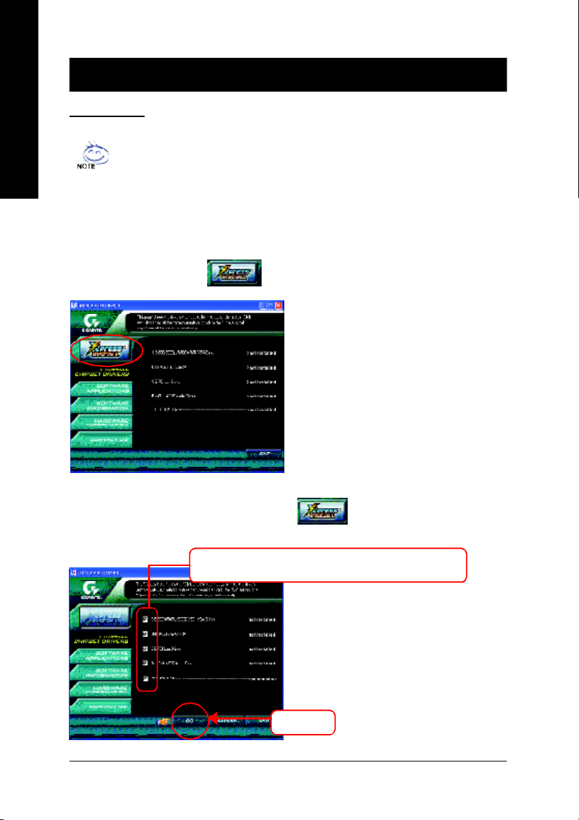
INSTALL CHIPSET DRIVER
This pag e sho ws the dri vers that need to be installed for the system . Click ea ch item to ins tall the
driver ma nually or switch to the to install the d rivers au tomatically.
Pictures below are shown in Windows XP
Insert the driver CD-title that cam e with your motherboard into your C D-ROM drive, the
driver CD -title will auto start and show the ins tallation guide. If not, please do uble click the
CD-ROM devic e ic on in "M y com puter", and ex ecute the setup.e xe.
Ma ssage: S ome device driv ers will restart yo ur
system a utomatically. After restarting y our
system the "Xpr ess Install" will continue to install
other drive rs.
The "Xpr ess Install" use s the"Click and Go" technology to install the drive rs automatically . Jus t select
the drivers you want then click the "GO" button. The will ex ecute the in stallation for y ou
by itsel f.
We recom mend that you install all com ponents in the list.
Click "GO".
- 36 -8S651M-RZ Series Motherboard
Page 37
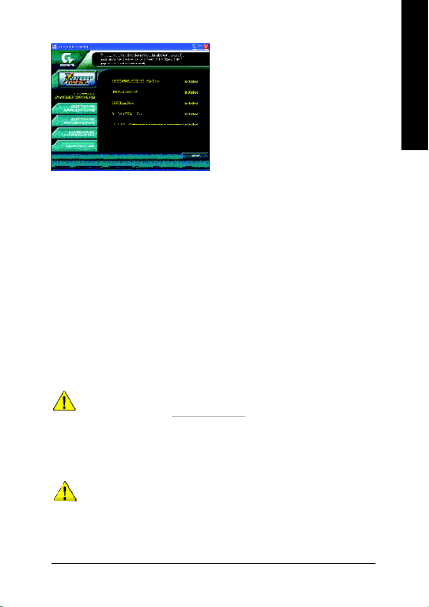
Driver i nstall finishe d!! you ha ve to reb oot
sys tem !!
Item Description
n SiS 650/6 50GL/6 50GX/65 1 V GA Driv er
VGA dr iver for V GA integrated Si S 650/6 50GL/65 0GX/65 1chipse t.
n USB Patch for W inXP
This patch driver can hel p you to r esol ve the USB dev ice wake u p S3 ha ng up i ssue in XP.
n SiS PCI Lan Driver
SiS 9 62L/9 63L LAN drive r.
n RealTek AC 97 Audi o Driv er
Install RealTek A C97 audio d rive r.
n SIS USB 2.0 Dr iver
It is recom m ended that you us e the M icroso ft Windows up date for the most up dated driv er
for XP /2K.
( * )
English
If your CD doesn't have SiS® USB2.0 driver, please download the USB2.0 driver
from Microsoft® website (www.microsoft.com) for USB2.0 devices support.
Please also note that Microsoft® USB2.0 driver is currently supported by Windows
XP and Windows 2000 only.
Once we get the latest SiS® USB2.0 driver for Windows 98 and Windows ME, we will
put the driver on GIGABYTE website asap. (http://www.gigabyte.com.tw).
For USB2 .0 driv er supp ort und er Windo ws XP oper ati ng syst em, ple ase use W ind ows
Ser vi ce Pack . A ft er inst all Win dow s Serv ice P ac k, it wi ll show a que st ion mar k "? " in
"Univer sal Serial Bus cont roller" u nder "Devi ce M anager". Please rem ove the q uestion m ark
and restar t the s ystem (S ystem will auto -detec t the r ight USB2.0 d river ).
“* ” For 8S65 1M -RZ onl y.
- 37 -
Driver Installation
Page 38

English
- 38 -8S651M-RZ Series Motherboard
Page 39

English
- 39 -
Driver Installation
Page 40

CONTACT US
Contact us via the information in this page all over the world.
— Tai wan
English
Gigabyte Technology Co., Ltd.
Address: No.6, Bau Chiang Road, Hsin-Tien, Taipei Hsien,
Taiwan, R.O.C.
Tel: 886 (2) 8912-4888
Fax: 886 (2) 8912-4004
Tech. Support:
http://tw.giga-byte.com /TechSupport/ServiceCenter.htm
Non-Tech. Support (Sales/Marketing issues):
http://ggts.gigabyte.com .tw/nontech.asp
Website: http://www.gigabyte.com .tw
— USA
G.B.T. INC.
Address: 17358 Railroad St, City of Industry, CA 91748.
Tel: 1 (626) 854-9338
Fax: 1 (626) 854-9339
Tech. Support:
http://www.giga-byte.com /TechSupport/ServiceCenter.htm
Non-Tech. Support (Sales/Marketing issues):
http://ggts.gigabyte.com .tw/nontech.asp
Website: http://w ww.giga-byte.com
— Germany
G.B.T. Technology Trading GmbH
Tel: 49-40-2533040
49-01803-428468 (Tech.)
Fax: 49-40-25492343 (Sales)
49-01803-428329 (Tech.)
Tech. Support:
http://de.giga-byte.com/TechSupport/ServiceCenter.htm
Non-Tech. Support (Sales/Marketing issues):
http://ggts.gigabyte.com .tw/nontech.asp
Website: http://www.gigabyte.de
— Japan
Nippon Giga-Byte Corporation
Website: http://www.gigabyte.c o.jp
— U.K
G.B.T. TECH. CO. LTD.
Tel: 44-1908-362700
Fax: 44-1908-362709
Tech. Support:
http://uk.giga-byte.com /TechSupport/ServiceCenter.htm
Non-Tech. Support (Sales/Marketing issues):
http://ggts.gigabyte.com .tw/nontech.asp
Website: http://uk.giga-byte.com
— The Netherl ands
Giga-Byte Technolog y B.V.
Address: Verdunplein 8 5627 SZ, Eindhoven, T he Netherlands
Tel: +31 40 290 2088
NL Tech.Support : 0900-GIGABYTE (0900-44422983, 0.2/M)
BE Tech.Support : 0900-84034 ( 0.4/M)
Fax: +31 40 290 2089
Tech. Support:
http://nz.giga-byte.com/TechSupport/ServiceCenter.htm
Non-Tech. Support (Sales/Marketing issues):
http://ggts.gigabyte.com .tw/nontech.asp
Website: http://www.giga-b yte.nl
— China
NINGBO G.B.T. Tech. T rading CO., Ltd.
Tech. Support:
http://cn.giga-byte.com/TechSupport/ServiceCenter.htm
Non-Tech. Support (Sales/Marketing issues):
http://ggts.gigabyte.com .tw/nontech.asp
Website: http://www.gigabyte.com .cn
Beijing
Tel: 86-10-82856054, 86-10-82856064, 86-10-82856094
Fax: 86-10-82856575
Chengdu
Tel: 86-28-85236930
Fax: 86-28-85256822
GuangZhou
Tel: 86-20-87586273
Fax: 86-20-87544306
Shanghai
Tel: 86-21-64737410
Fax: 86-21-64453227
Shenyang
Tel: 86-24-23960918, 86-24-23960893
Wuhan
Tel: 86-27-87854385, 86-27-87854802
Fax: 86-27-87854031
Xian
Tel: 86-29-5531943
Fax: 86-29-5539821
- 40 -8S651M-RZ Series Motherboard
 Loading...