

Page 1
Operator's Manual
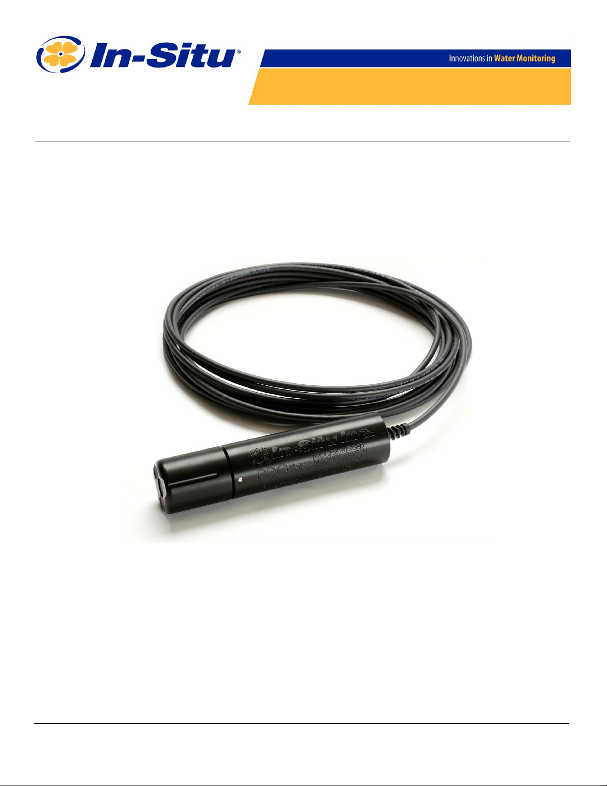
RDO®PRO-X Process Optical Dissolved Oxygen Probe
Informationsubject to change without notice. In-Situ, In-Situ logo, Baro Merge, BaroTROLL, HERMIT, HydroVu™, iSitu, Pocket-Situ, RDO,
RuggedCable, RuggedReader, SmarTROLL™, TROLL, VuSitu, and Win-Situ are trademarks or registeredtrademarks of In-Situ Inc.©2008-
2015. All rights reserved. This product may be covered by patents identified at www.in-situ.com/patents
0090102 | 2019-05-10
Page 2
Copyright © 2008-2015 by In-Situ All rights reserved.
This document contains proprietary information which is protected by copyright. No part of this document may be
photocopied, reproduced, or translated to another language without the prior written consent of In-Situ
In-Situ makes no warranty of any kind with regard to this material, including, but not limited to, its fitness for a particular
application. In-Situ will not be liable for errors contained herein or for incidental or consequential damages in connection with
the furnishing, performance, or use of this material.
In no event shall In-Situ Inc. be liable for any claim for direct, incidental, or consequential damages arising out of, or in
connection with, the sale, manufacture, delivery, or use of any product.
In-Situ and the In-Situ logo, Win-Situ, TROLL, Baro Merge, BaroTROLL, HERMIT, HyroVu™, iSitu, Pocket-Situ, RDO,
RuggedCable, RuggedReader, TROLL, and VuSitu™, Win-Situ are trademarks or registered trademarks of In-Situ Inc.
Microsoft and Windows are registered trademarks of Microsoft Corporation. Pentium is a registered trademark of Intel. Tefzel
and Delrin are registered trademarks of E. I. DuPont de Nemours and Company. Viton is a registered trademark of DuPont
Dow Elastomers. Kellems is a registered trademark of Hubbell Inc. Alconox is a registered trademark of Alconox Company.
Lime-A-Way is a registered trademark of Reckitt Benckiser. Android is a trademark of Google Inc. iPod and iPhone are
trademarks of of Apple Inc., registered in the U.S. and other countries. The Bluetooth word mark and logos are registered
trademarks owned by the Bluetooth SIG, Inc. and any use of such marks by In-Situ Inc. is under license. NIST is a registered
trademark of the National Institute of Standards and Technology, U.S.A. Other brand names and trademarks are property of
their respective owners.
The presence of the Waste Electrical and Electronic Equipment (WEEE) marking
on the product indicates that the device is not to be disposed via the
municipal waste collection system of any member state of the European
Union.
For products under the requirement of WEEE directive, please contact your
distributor for the proper decontamination information and take back
program, which will facilitate the proper collection, treatment, recovery,
recycling, and safe disposal of the device.
2
Page 3
Table of Contents
1 Optical RDO PRO-X Dissolved Oxygen Probe Specifications
2 Introduction
System Description 6
Serial Numbers 7
Unpack the Probe 7
3 Calibrate the RDO PRO-X Probe
1-Point Calibration 9
Water-Saturated Air 9
2-Point Calibration 9
100% and 0% Saturation 9
4 Probe Deployment
5 Care and Maintenance
Clean the Sensor Cap 12
Clean the Optical Window 12
Clean the Probe 12
Sensor Cap Storage 12
Replace the Sensor Cap 12
Maintain Desiccant 13
5
6
9
11
12
6 Controller Requirements and Connections
Wiring Overview 14
Analog (4-20 mA) 3-wire 15
SDI-12 (3-wire) 16
Modbus Master with Built-in RS485 17
Modbus Master with Built-in RS232 (Converter Required) 18
Converter 19
Power Connections 19
Communications 19
7 Modbus Registers
Common Registers 20
Sensor Status Registers 20
Device Specific Register 0042 Data Quality ID 20
Device Specific Registers 21
8 Dissolved Oxygen Equations
Dissolved Oxygen Concentration 22
Dissolved Oxygen, % Saturation 23
9 Calibration Registers
Live Salinity Value 24
Default Salinity Value 24
Live Barometric Pressure 24
Default Barometric Pressure 24
14
20
22
24
3
Page 4
100% Saturation Calibration Values 24
0% Saturation Calibration Values 24
Calibration Slope and Offset 25
Entering Calibration Registers 25
Calibration Calculations 26
10 Service
Sensor Health Table 27
11 Appendix A - Communication Device
Install and Open the Software 28
Connect the Probe to the Communication Device 28
12 Declaration of Similarity
27
28
29
4
Page 5
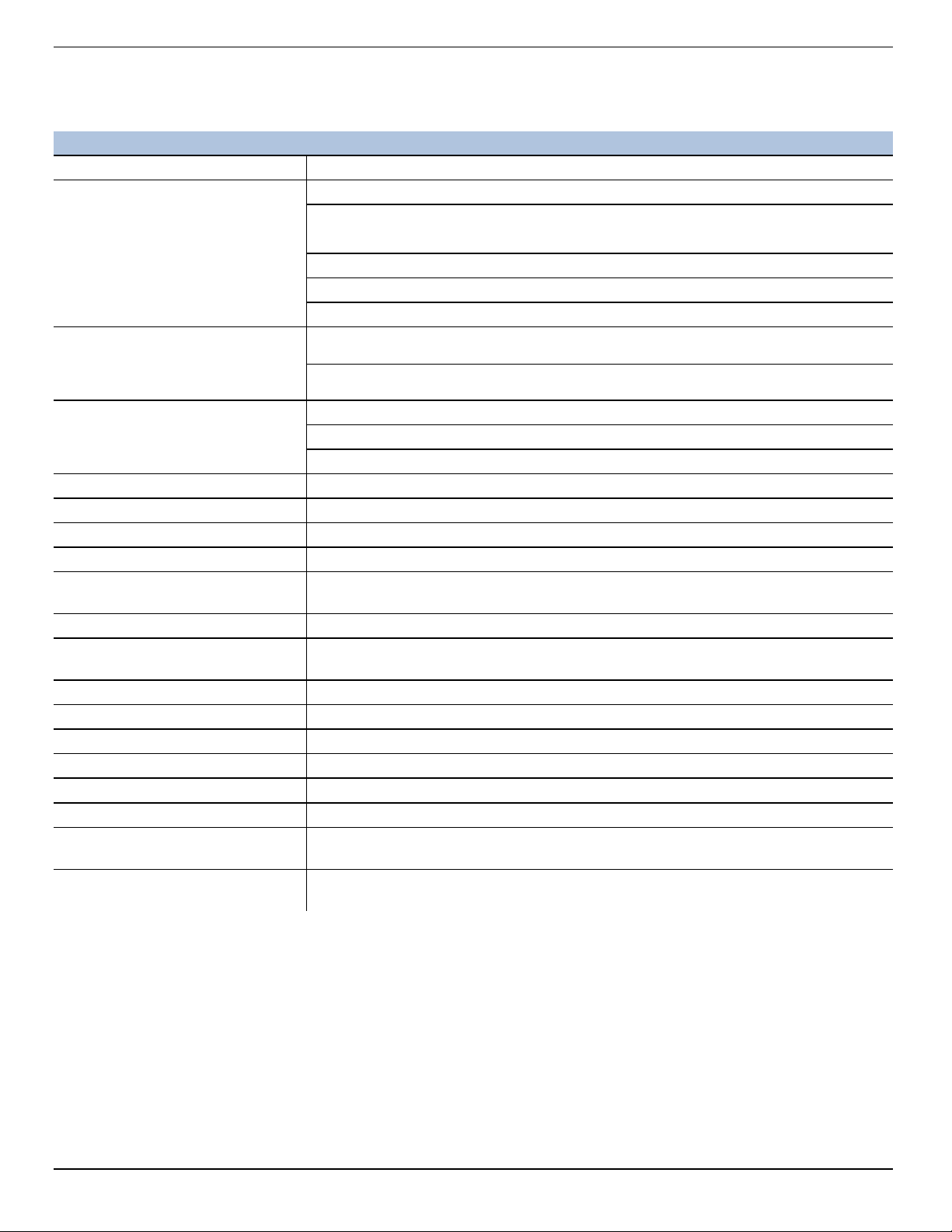
Optical RDO PRO-X Dissolved Oxygen Probe Specifications
Optical RDO PRO-X Dissolved Oxygen Probe
Sensor Type Optical (luminescent) dissolved oxygen sensor
Range: 0 to 60 mg/L concentration
Accuracy: ±0.1 mg/L from 0 to 20 mg/L
RDO PRO-X Probe
RDOClassic Cap
RDO-X Sensor Cap
RDOFast Cap
Temperature sensor
Transmitter/local display Optional, or use with Con TROLL PRO System
Communications options Modbus/RS485, 4-20 mA, SDI-12
Max. power consumption 50 mA at 12 VDC
Measure current 6 mA typical at 24 VDC
Idle current (no measurement or
communication)
Maximum cable length Up to 1,219 m (4,000 ft) (for Modbus and 4-20 mA) or up to 60.96 (200 ft) for SDI-12
Cable options
Internal mounting thread 1¼ - 11 ½ NPT
IP rating IP-67 with cap off, IP-68 with cap installed
Compliance Heavy industrial, IEC 61000-6-2:2005
Salinity compensation Fixed or real-time capable (using controller)
Barometric pressure Fixed or real-time capable (using controller)
Maximum pressure 150 psi from 0 to 50° C; 300 psi @ 25° C
Warranty
Methods
±2% of reading from 20-60 mg/L
Resolution: 0.01 mg/L
Response time: T90 < 45 sec; T95 < 60 sec @ 25°C
Storage conditions: -5° to 60° C (23° to 140° F)
Usage life: 2 years typical
Storage conditions: 1° to 60° C (33° to 140° F), in factory container
Range: 0° to 50° C (32° to 122° F)
Accuracy: ±0.1° C typical
Resolution: 0.01° C
160 µA typical at 24 VDC
10 m fixed stripped-and-tinned; Twist-lock connector with user-selectable cable
length
Probe: 3 years from date of shipment
RDO-X Sensor Cap: 2 years in typical applications
Standard Methods 4500-O; In-Situ Methods 1002-8-2009,1003-8-2009, 1004-8-2009
(EPA approved)
5
Page 6
Introduction
The RDO PRO-X Probe is a rugged, reliable instrument designed to deliver accurate dissolved oxygen (DO) data across a
wide measurement range and to reduce maintenance costs. The probe features the latest optical technology for DO
measurement.
System Description
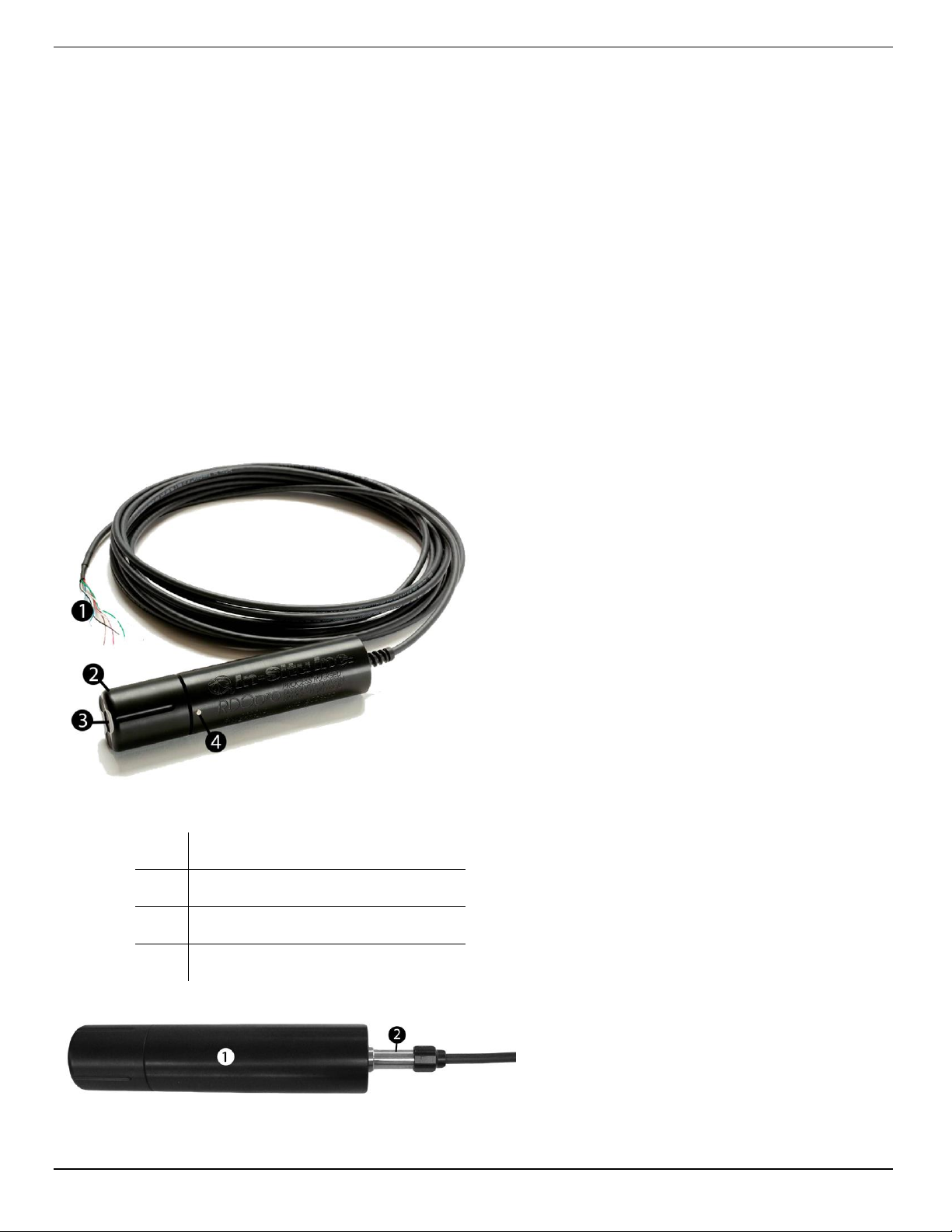
The RDO PRO-X system consists of the following items.
l Black probe body with removable nose cone
l Optical RDO-X Sensor Cap, Classic Cap, or Fast Cap
l Titanium thermistor
RuggedCable System
l 10-m standard length with stripped-and-tinned ends
l Customized lengths with titanium twist-lock connectors
1 Cable end, stripped-and-tinned
2 Nose cone
3 RDO-X Sensor Cap
4 Thermistor
6
Page 7
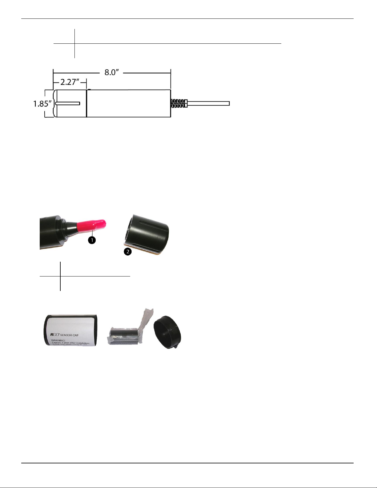
1 Probe
2 Cable end, twist-lock connector and RuggedCable System
Serial Numbers
The probe serial number is engraved on the side of the unit. The cap serial number is programmed on the memory chip inside
the cap.
Unpack the Probe
1. Remove the probe from the box and other packaging materials.
2. Unscrew the nose cone from the probe and remove the red protective dust cap from the sensor. Save the dust cap
for later use.
1 Dust cap
2 Nose cone
3. Remove the RDO cap from the storage sleeve.
4. Align the arrow on the cap with the index mark on the probe and firmly press the cap onto the probe, without
twisting, until it seals over the probe body.
7
Page 8
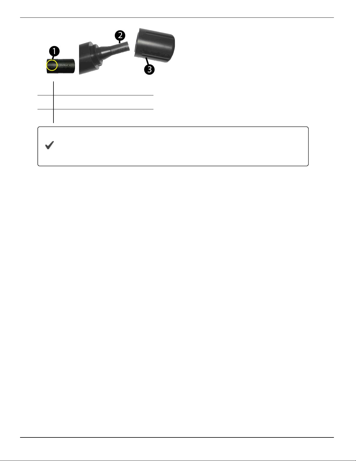
1 Alignment arrow on cap
2 Cap installed over lens
3 Nose cone
Do not allow moisture or atmospheric humidity inside the cap. Keep the cap in its sealed
package until you are ready to install it. Install promptly. Ensure that O-ring grooves are dry and
that the O-ring is not rolled or pinched inside the cap.
The typical cap lifetime is two years after the first reading has been taken.
5. Reattach the nose cone.
8
Page 9
Calibrate the RDO PRO-X Probe
Calibrate the sensor with Win-Situ 5 software or the VuSitu mobile app, or calibrate directly with your controller.
1-Point Calibration
The optical Rugged Dissolved Oxygen sensor is very stable. The factory calibration should produce readings within 3%
accuracy. If you require readings with greater accuracy we recommend that you perform a 1-point, 100% water-saturated air
calibration as described below.
Water-Saturated Air
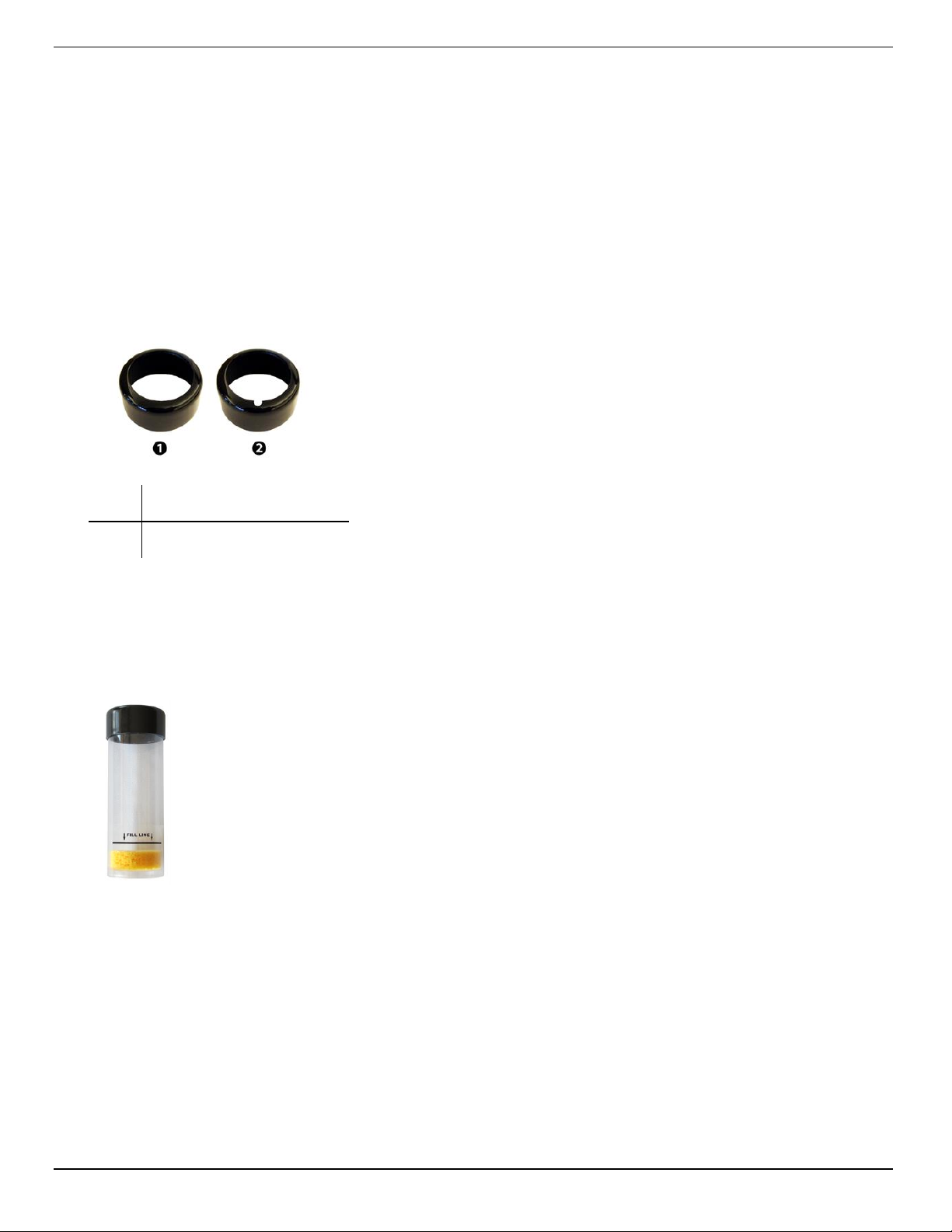
1. Remove the storage cap from the top of the calibration chamber and replace it with the vented calibration cap.
1 Storage cap
2 Vented calibration cap
Figure 6.1 Storage cap and vented calibration cap shown together
2. Place the sponge wafer in the bottom of the calibration chamber and saturate with approximately 10 mL water.
3. Gently dry the instrument and sensing material with a paper towel, making sure there is no water or debris on the
instrument or on the sensing surface.
4. Place the instrument into the calibration chamber about 2.5 cm (1 in.) above the water-saturated sponge.
Figure 6.2 Calibration chamber with water-saturated sponge
5. Allow 5 to 10 minutes for temperature stabilization prior to starting the calibration procedure. Do not leave the
instrument in the calibration chamber for more than 30 minutes. This can allow condensation to form on the
sensing material, which will produce false low readings after calibration. If condensation does occur, remove the
instrument, dry the sensing material, place the instrument in the chamber, and calibrate.
2-Point Calibration
100% and 0% Saturation
We recommend that you perform the 0 % oxygen calibration only if you intend to measure dissolved oxygen at a
concentration of less than 4 mg/L.
9
Page 10
1. Set up the calibration procedure as previously described, and perform a water-saturated air calibration.
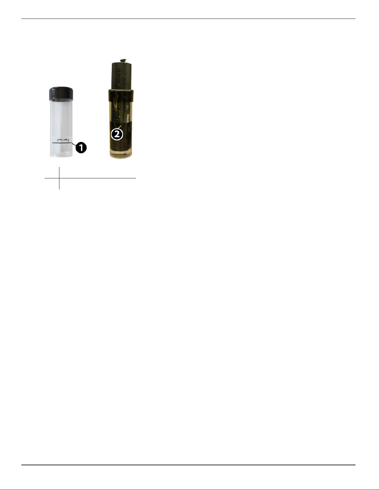
2. Remove the water-saturated sponge from the calibration chamber and fill the chamber to the fill line with
approximately 60 mL of fresh sodium sulfite solution.
1 Fill line
2 Temperature sensor
2. Place the instrument into the solution. Leave at least 13 mm (0.5 in.) between the surface of the sensing material
and the bottom of the chamber.
3. Ensure that the temperature sensor is completely submerged in the solution.
4. Allow at least 5 minutes for the temperature to stabilize prior to performing the calibration procedure.
5. Once calibration is complete, remove the sensor, and thoroughly rinse to remove all of the sodium sulfite.
10
Page 11
Probe Deployment
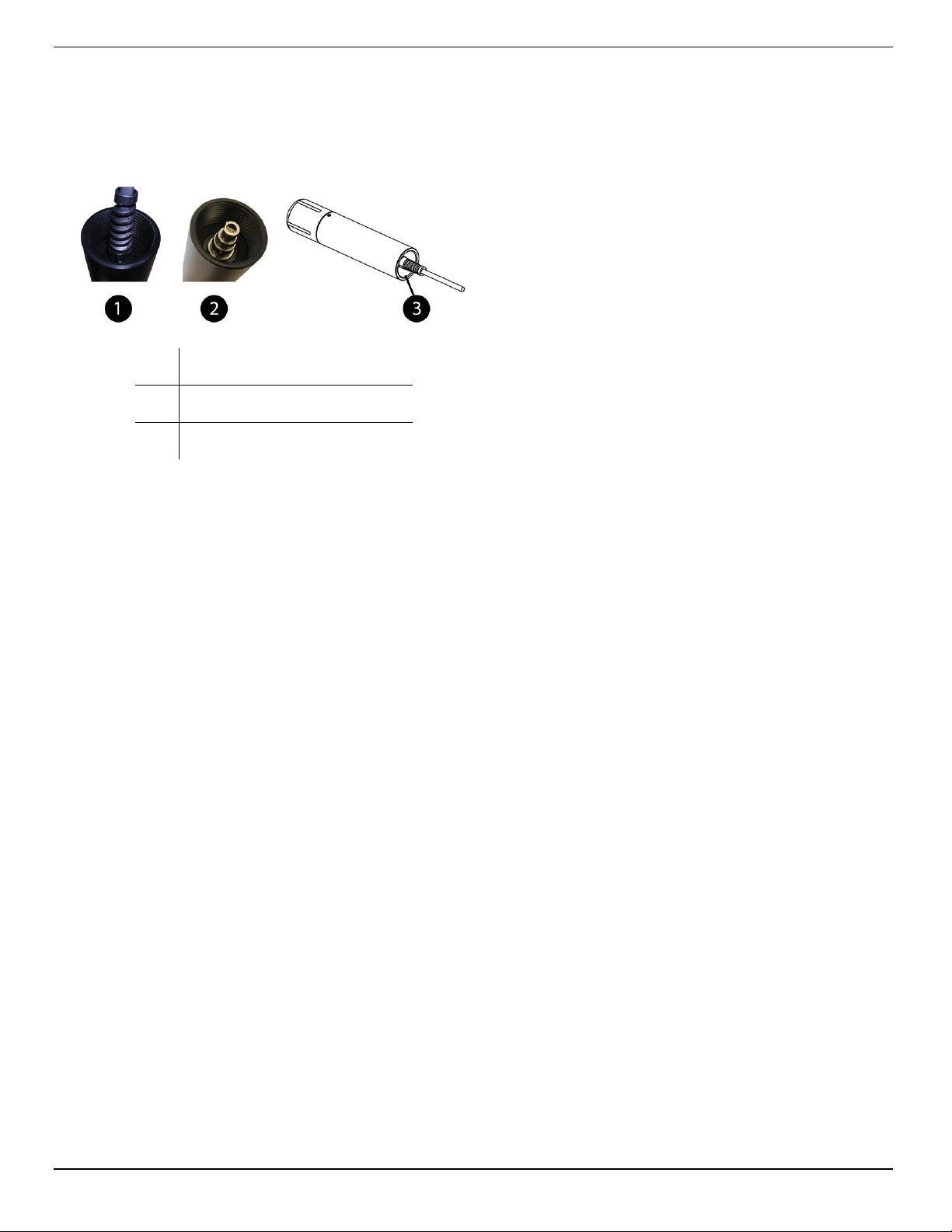
The cable end of the RDO PRO-X Probe is internally threaded (1¼ – 11½ NPT) and can be attached to a male threaded pipe.
When deployed, make sure that the nose cone and thermistor are completely submerged.
1 10 m cable attached
2 Twist-lock connector
3 1 1/4 NPT threading
11
Page 12
Care and Maintenance
Clean the Sensor Cap
1. The cap and nose cone must remain on the probe.
2. Rinse the sensor with clean water from a squirt bottle or spray bottle.
3. Gently wipe with a soft-bristled brush or soft cloth if biofouling is present. Use Alconox to remove grease.
4. If extensive fouling or mineral build-up is present, soak the cap end in vinegar for 15 minutes, then soak in
deionized (DI) water for 15 minutes.
Do not use organic solvents—they will damage the sensing element. Do not remove the cap
from the sensor prior to cleaning.
5. After cleaning, perform a 1- or 2-point user calibration or calibration check.
Clean the Optical Window
1. Clean the optical window only when you change the cap. See full instructions in the sensor cap replacement kit.
2. Remove the cap and gently wipe the lens with the supplied lens cloth.
Do not wet the lens area with water or any solution. Use only the supplied lens cloth for
cleaning. Do not use any other cloth or material.
Clean the Probe
With the RDO cap installed on probe, gently scrub the probe with a soft-bristled brush or nylon dish scrubber. Use Alconox to
remove grease or other matter. Soak in vinegar and DI water to remove mineral deposits or extensive fouling.
Sensor Cap Storage
Prior to installation—Store in factory supplied container.
Installed—Store in the calibration chamber with the storage cap attached and a few drops of clean water.
Replace the Sensor Cap
1. Remove the probe nose cone.
2. Use a lint-free cloth to remove any moisture from the probe.
3. Pull the used RDO cap off of the sensor, without twisting.
4. Remove the existing O-rings from the sensor.
Ensure that there is no moisture in the O-ring grooves. Do not touch or clean the lens with
anything other than the supplied lens wipe.
5. Use your finger to apply a very light layer of silicone-based lubricant around the O-ring grooves.
6. Place the O-rings on the sensor. Apply another thin layer of lubricant to the O-rings and grooves.
Note: Do not transfer grease to the lens or sensor pins.
7. Clean the sensor lens with the wipe provided in the kit and allow it to thoroughly dry. Inspect for scratches or dirt.
12
Page 13
8. Remove the new cap from its sealed packaging and attach it to the sensor, being careful to press firmly, without
twisting, until it seals over the lens. Make sure that the O-rings are not pinched or rolled between the cap and
sensor.
9. Replace the nose cone.
10. Perform a 1- or 2-point calibration.
Maintain Desiccant
Desiccant installed in a controller or transceiver protects probe electronics from condensation. A desiccant pack changes
color from blue to pink as it becomes saturated with moisture.
It is extremely important to use the proper size desiccant for your deployment and to
change desiccant often. Desiccant should be changed before the entire pack has turned
pink, and you should use enough to effectively keep cables and probes dry until your next
scheduled maintenance. Desiccant lifespan is dependent on site conditions.
13
Page 14
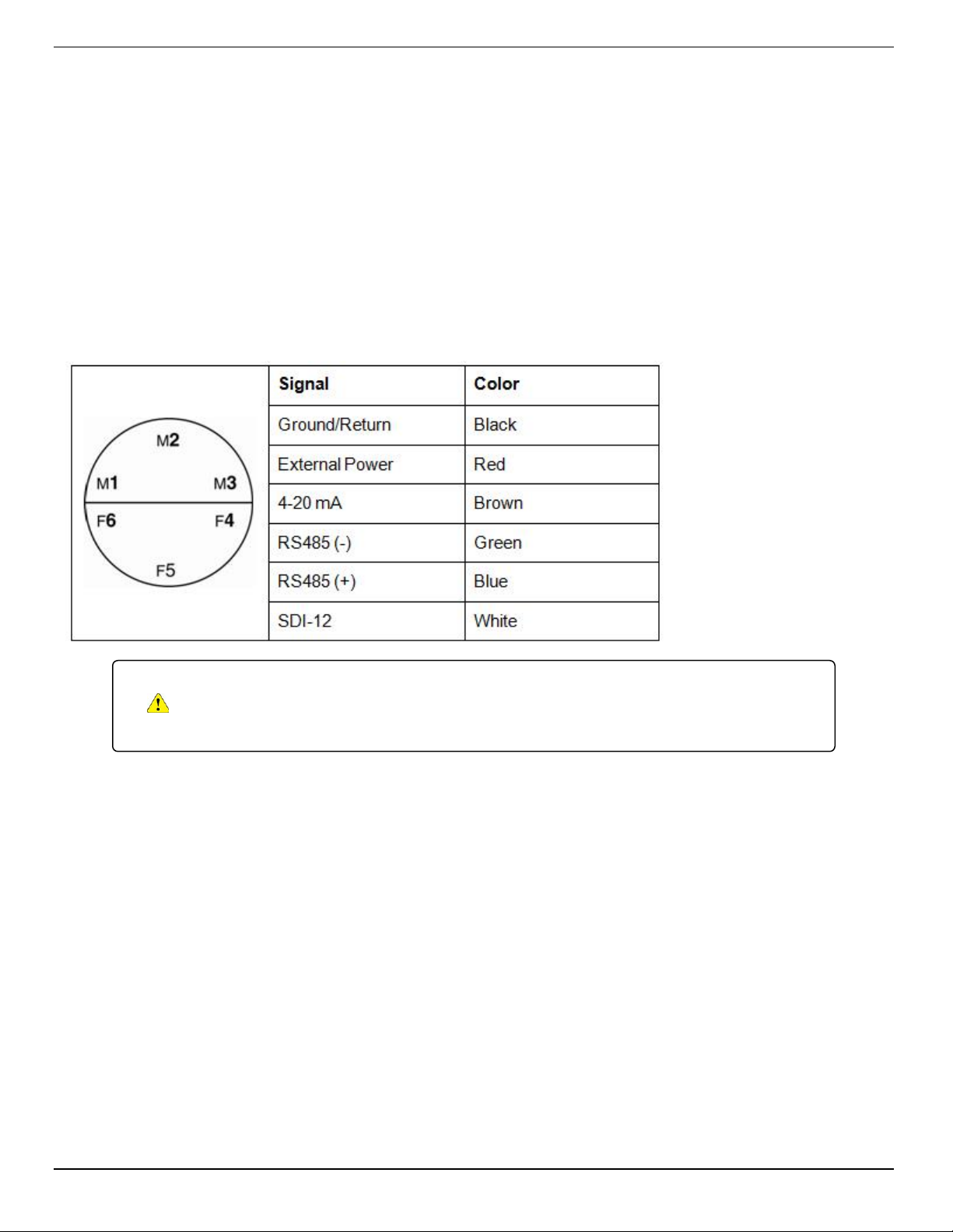
Controller Requirements and Connections
The RDO PRO-X Probe may be connected to a controller or logger for communication via the following options.
l Analog (4-20 mA) provides a configurable 4-20 mA current loop output
l SDI-12
l RS485 Modbus
l RS232 to Modbus
Wiring Overview
Refer to diagrams on the following pages. Trim and insulate unused wires. The shielded wire should be connected to a
chassis ground or earth ground.
The inside of the controller must be kept free of moisture and humidity. Condensed
moisture can migrate through the wiring and cause the probe to fail. Therefore, desiccant
should be installed in the controller and be replaced on a regular basis.
14
Page 15
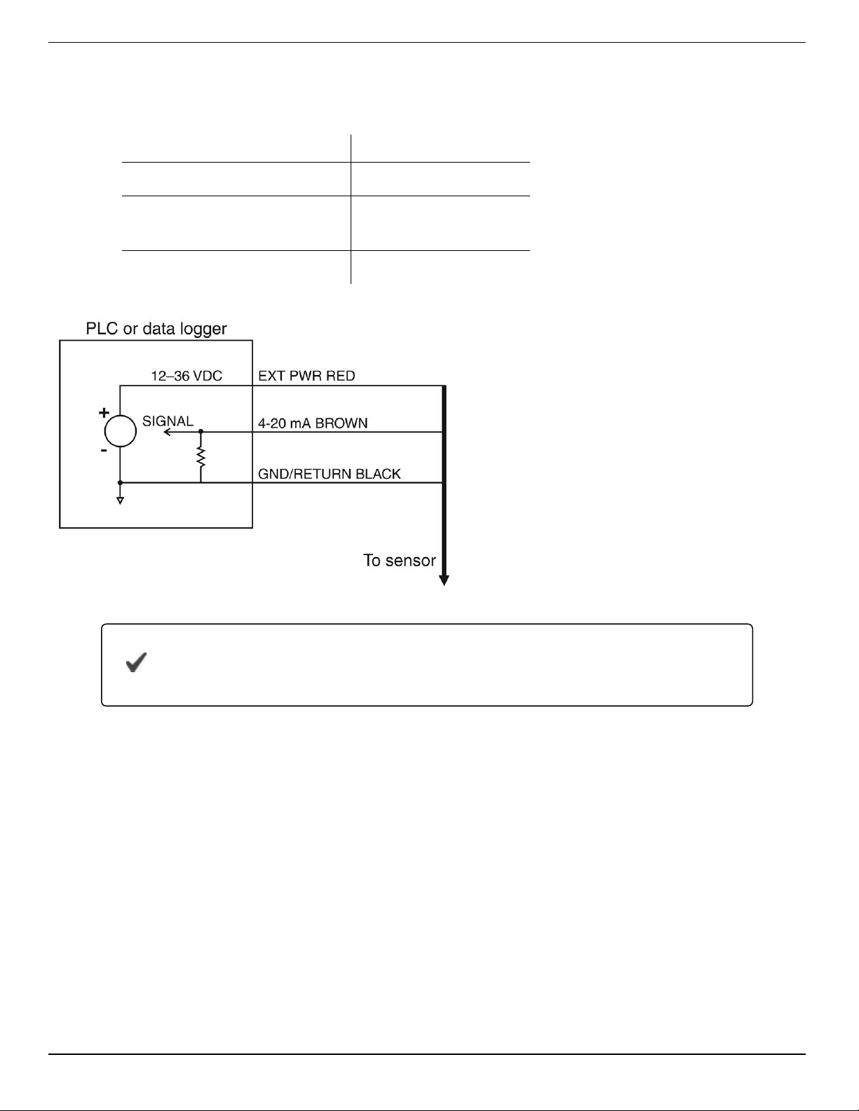
Analog (4-20 mA) 3-wire
Signal Color
Ground/Return Black
External Power (12-36
VDC)
Red
4-20 mA Brown
Cable length must not exceed 1219 m (4000 ft.)
Analog signal must be enabled in Win-Situ 5 Software or the Comm Kit Software prior to
use.
15
Page 16
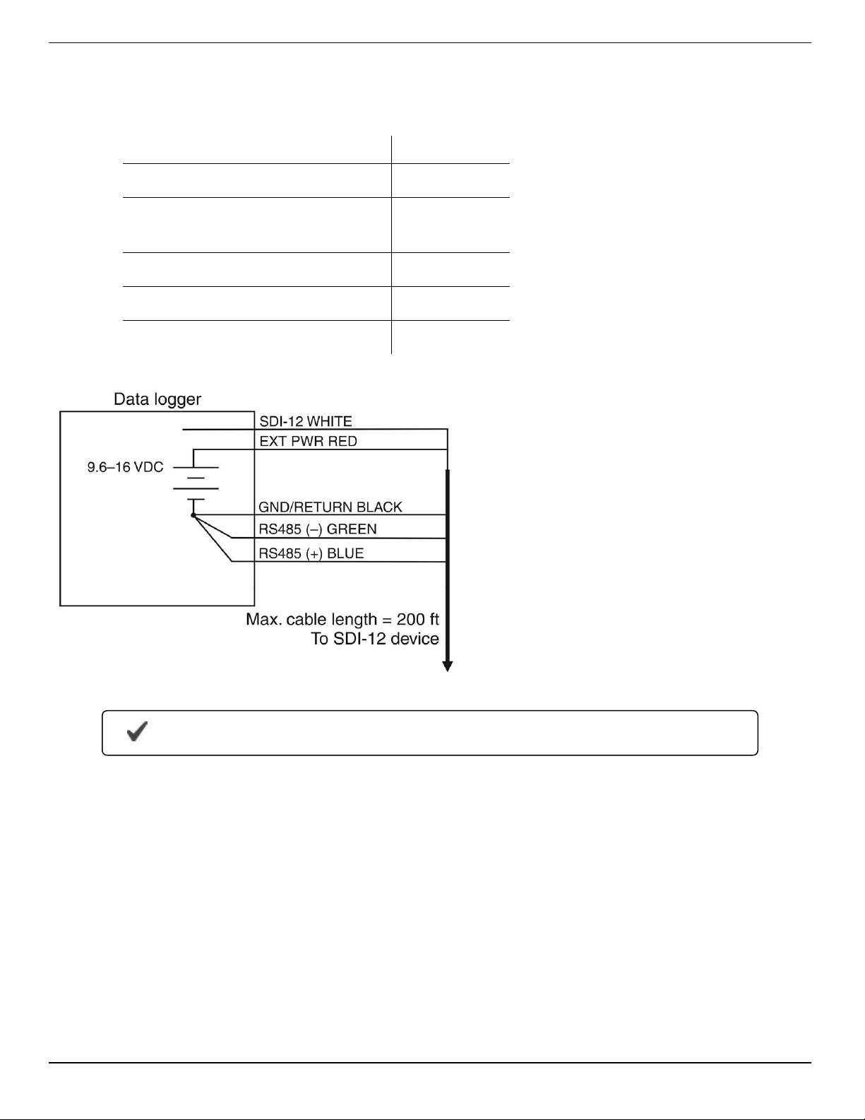
SDI-12 (3-wire)
Signal Color
Ground/Return Black
External Power (9.6-16
VDC)
Red
RS485 (-) Green
RS485 (+) Blue
SDI-12 White
Cable length must not exceed 60.96 m (200 ft.)
16
Page 17
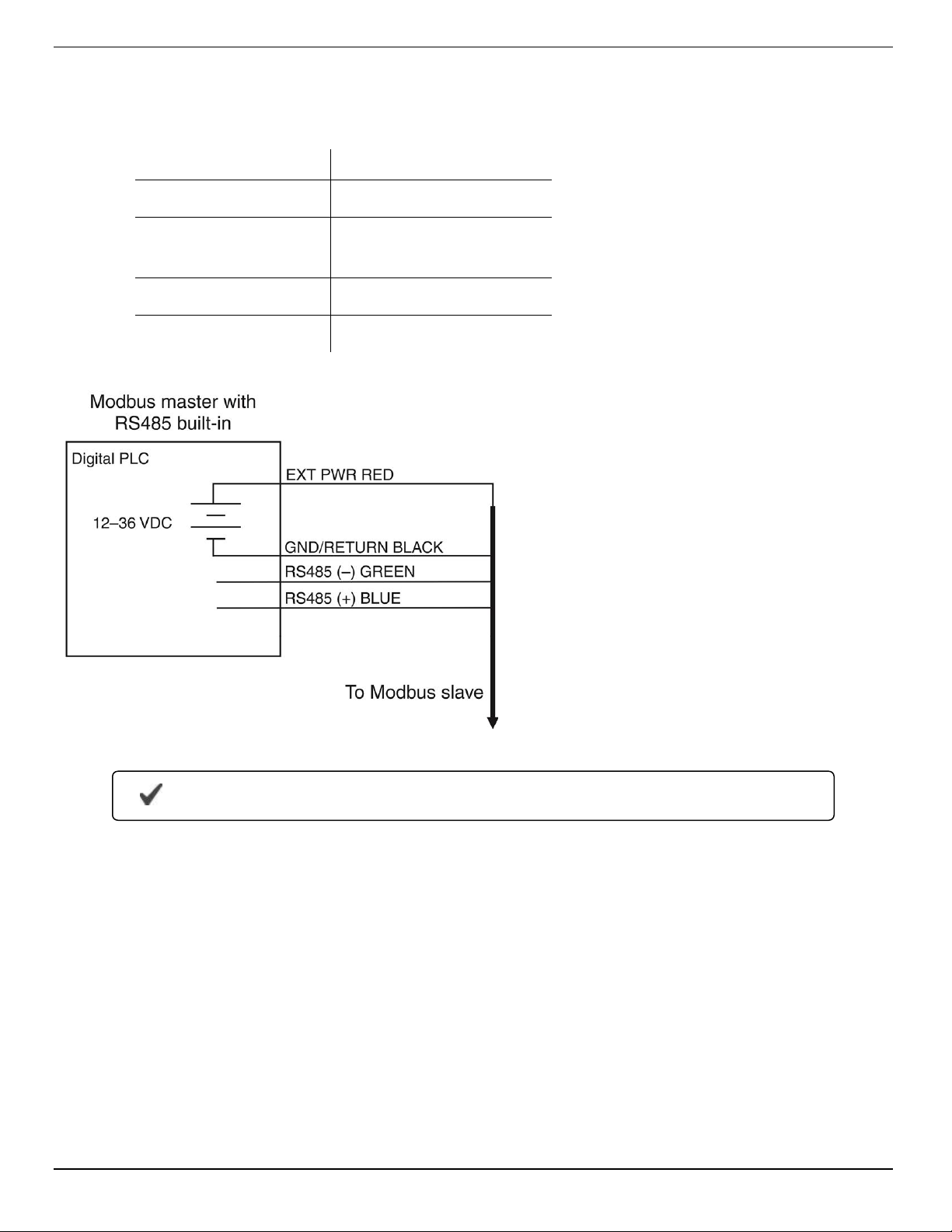
Modbus Master with Built-in RS485
Signal Color
Ground/Return Black
External Power
(12-36 VDC)
Red
RS485 (-) Green
RS485 (+) Blue
Cable length must not exceed 1219 m (4000 ft.)
17
Page 18
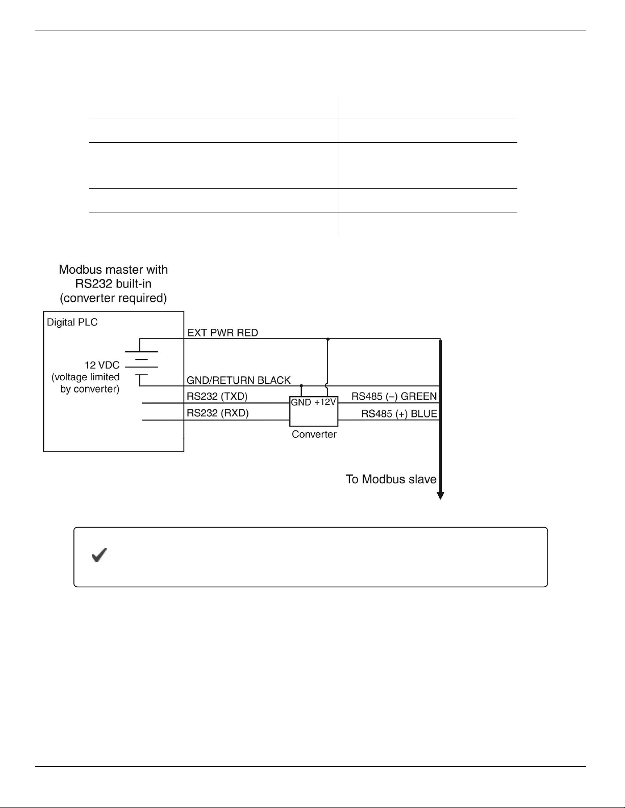
Modbus Master with Built-in RS232 (Converter Required)
Signal Color
Ground/Return Black
External Power
(12 VDC, voltage limited by converter)
RS485 (-) Green
RS485 (+) Blue
Red
Cable between converter and master must not exceed 60.96 m (20 ft.)
Cable between master and slave must not exceed
1219 m (4000 ft.)
18
Page 19
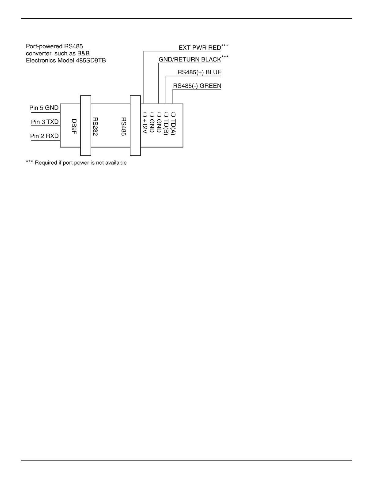
Converter
Power Connections
The red wire provides power for all system modes. Analog output is disabled by default. However, the 4-20 mA current loop
output can be continuous in Modbus or SDI-12 mode as long as Modbus device register 9507 is set to 1.
Communications
The device automatically switches between Modbus and SDI-12 modes depending on which of the two interfaces has
activity. Modbus and SDI-12 cannot be used at the same time—whichever one is currently in use will block communication
on the other.
19
Page 20
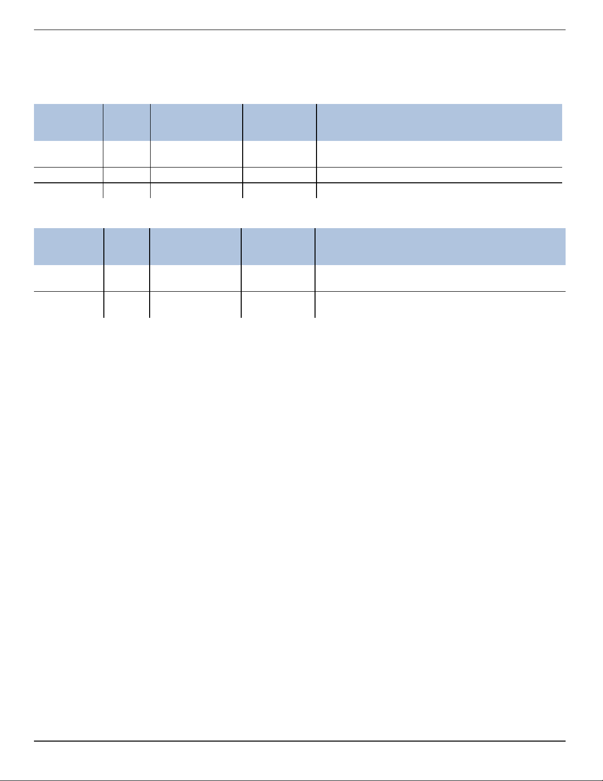
Modbus Registers
Common Registers
Mode &
Register Size
9001 1 R/W ushort
9002 2 R/W ulong Device serial number
9004 3 R/W time Manufacture date
Sensor Status Registers
Register Size
0005 3 R1 time
0008 3 R1 time
Device Specific Register 0042 Data Quality ID
Access Level
(R/W)
Mode &
Access Level
(R/W)
Data Type Description
Device ID = 19 for RDO Titan31 for RDO PRO-X35 for
RDOBlue
Data Type Description
Cap start date/time
0 = no cap
Cap end of usable life date/time
0 = no cap
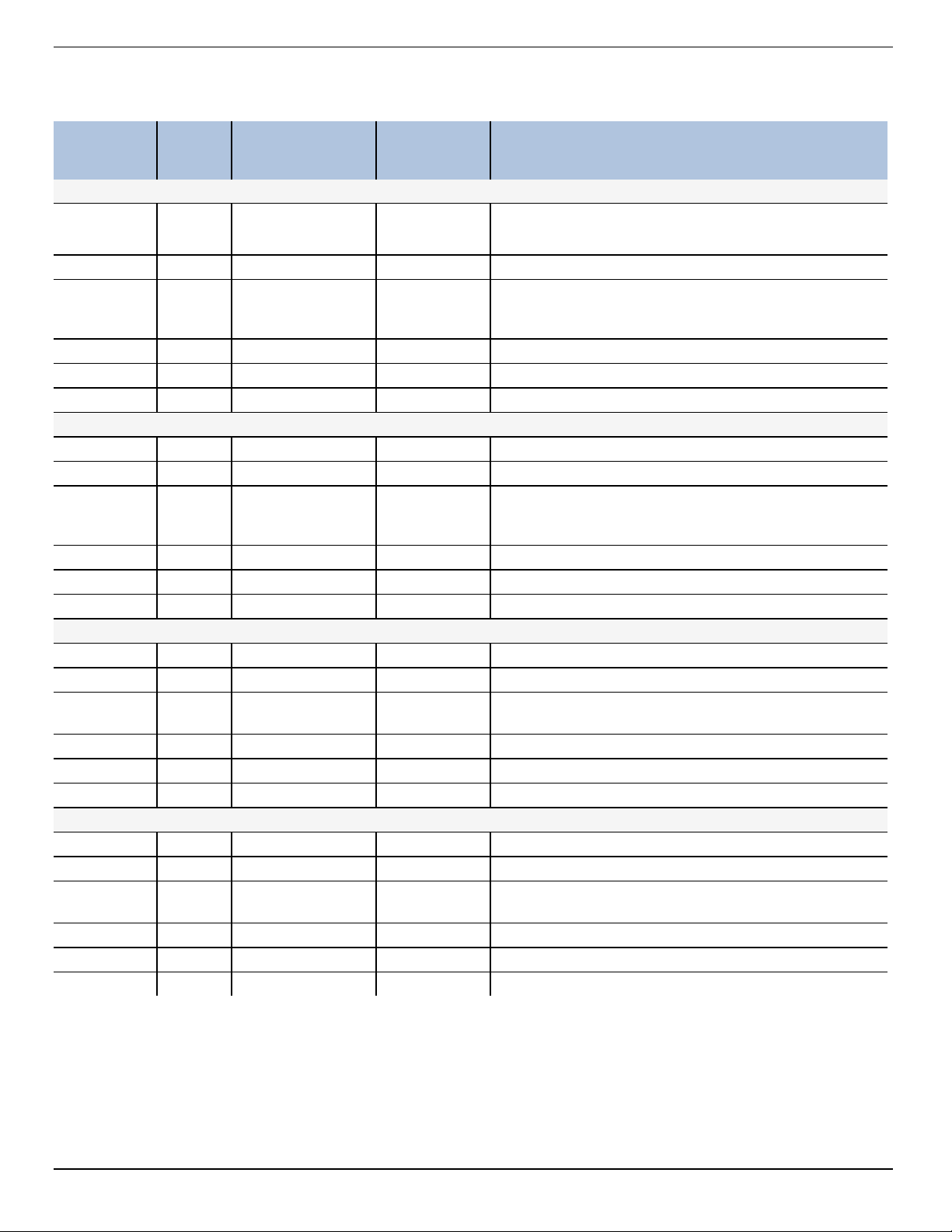
Register 0042 is responsible for returning the various data quality IDs for the RDO sensor. For a list of the Data Quality IDs
and definitions, see the Sensor Health Table in the Service and Troubleshooting section of this manual.
20
Page 21
Device Specific Registers
Mode &
Register Size
0038 2 R1 float
0040 1 R1 ushort Parameter ID = 20
0041 1 R1/W2 ushort
0042 1 R1 ushort Data quality ID (See the Sensor Health Table)
0043 2 R1/W3 float Offline sentinel value (default = 0.0)
0045 1 R1 16 bits Available units = 0x0030 (48)
0046 2 R1 float Measured value
0048 1 R1 ushort Parameter ID = 1
0049 1 R1/W2 ushort
0050 1 R1 ushort Data quality ID
0051 2 R1/W3 float Offline sentinel value (default = 0.0)
0053 1 R1 16 bits Available units = 0x00030 (3)
0054 2 R1 float Measured value
0056 1 R1/W2 ushort Parameter ID = 21
0057 1 R1/W2 ushort
0058 1 R1 ushort Data quality ID
0059 2 R1/W3 float Offline sentinel value (default = 0.0)
0061 1 R1 16 bits Available units = 0x0001 (1)
0062 2 R1 float Measured value
0064 1 R1 ushort Parameter ID = 2 (pressure)
0065 1 R1/W2 ushort
0066 1 R1 ushort Data quality ID
0067 2 R1/W3 float Offline sentinel value (default = 0.0)
0069 1 R1 16 bits Available Units = 0x0200 (512)
Access Level
(R/W)
Data Type Description
Dissolved Oxygen Concentration
Measured value, C
Units ID
117 = mg/L (default)
118 = ug/L
Temperature
Units ID
1= °C (default)
2= °F
Dissolved Oxygen % Saturation
Units ID
177 = percent saturation (default)
Oxygen Partial Pressure
Units ID
26 = torr (default)
o
21
Page 22
Dissolved Oxygen Equations
Dissolved Oxygen Concentration
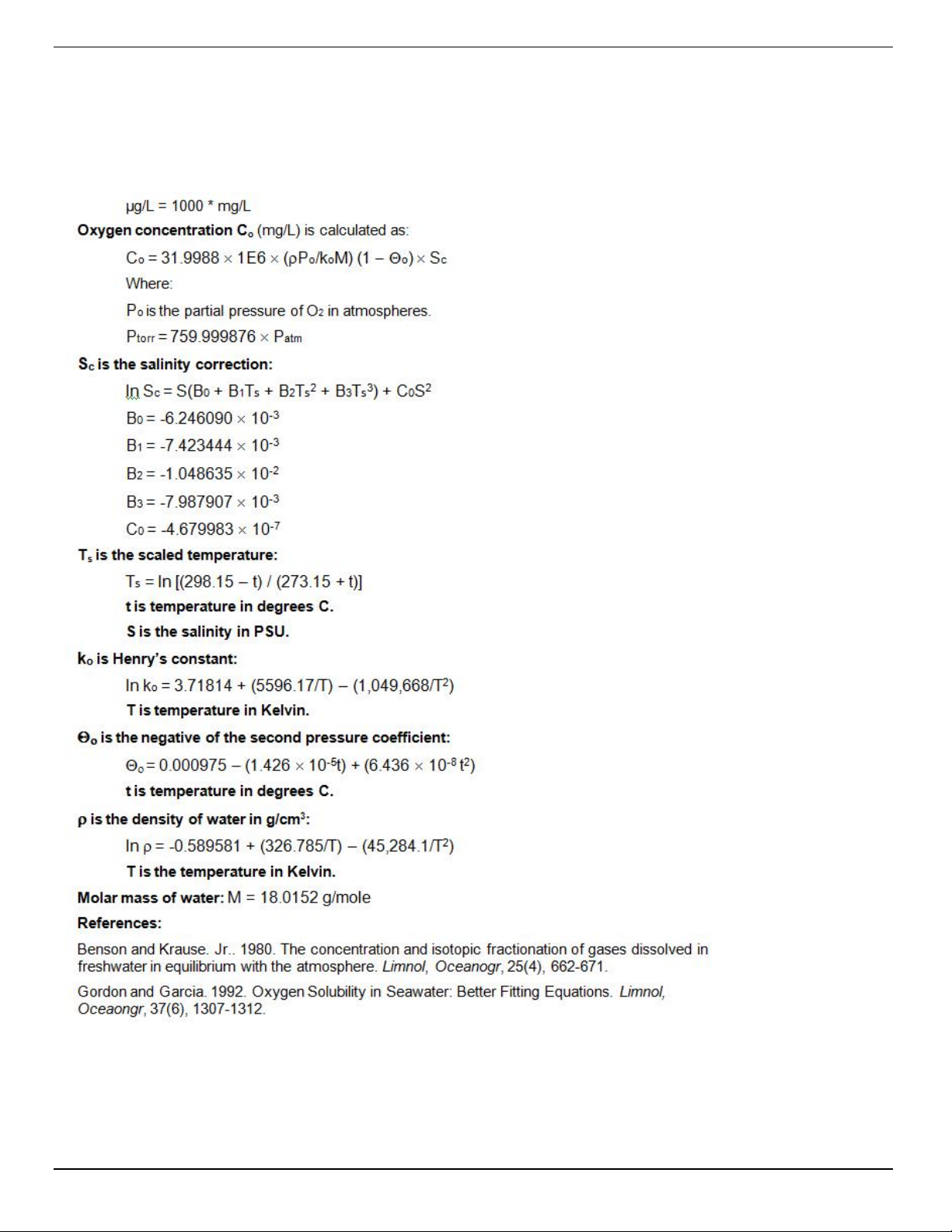
DO concentration is internally calculated in mg/L. Conversion to other units is as follows:
22
Page 23
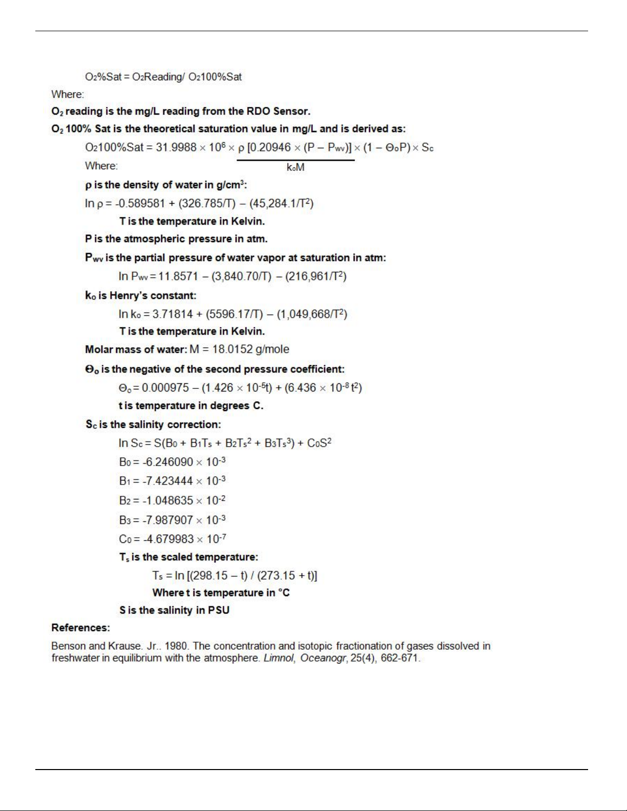
Dissolved Oxygen, % Saturation
23
Page 24
Calibration Registers
Register Size
0118 2 R1/W3 float Live salinity value (PSU)
0120 2 R1/W3 float Default salinity value (PSU, default = 0.0)
0122 2 R1/W3 float Live barometric pressure (mbar)
0124 2 R1/W3 float Default barometric pressure (mbar, default = 1013.25)
0126 2 R1/W3 float 100% saturation calibration reading (mg/L)
0128 2 R1/W3 float 100% saturation temperature reading (°C)
0130 2 R1/W3 float 100% saturation salinity value (PSU)
0132 2 R1/W3 float 100% saturation barometric pressure (mbar)
0134 2 R1/W3 float 0% saturation calibration reading (mg/L)
0136 2 R1/W3 float 0% saturation temperature reading (°C)
0138 2 R1/W3 float Calibration slope (default = 1.0)
0140 2 R1/W3 float Calibration offset (default = 0.0)
Mode & Access
Level (R/W)
Data Type Description
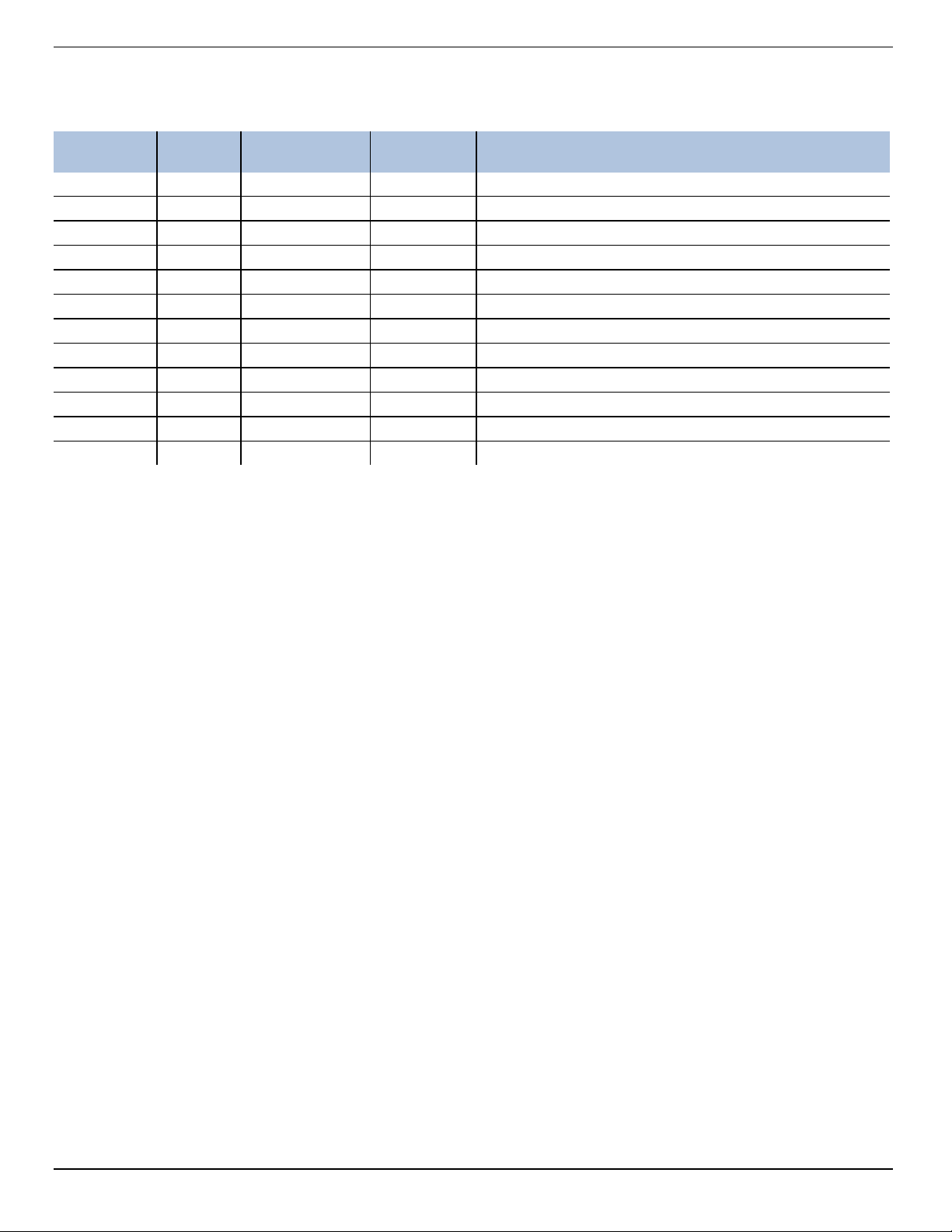
Live Salinity Value
The live salinity value is used to correct the oxygen concentration value for salinity. Values must be written in Practical
Salinity Units (PSU) in the range 0 to 42 PSU. This is not a measured parameter.
Default Salinity Value
The default salinity value is loaded into the live salinity value register when power is first applied to the probe. The default
salinity value is used in calculations until a live salinity value is written. This is not a measured parameter.
Live Barometric Pressure
The live barometric pressure is used in the calculation of percent saturation and to determine the theoretical saturation point
during calibration. Values must be written in millibars in the range 506.625 to 1114.675 mbar. This is not a measured
parameter.
Default Barometric Pressure
The default barometric pressure is loaded into the live barometric pressure register when power is applied to the probe. The
default barometric pressure is used in calculations until a live barometric pressure is written. This is not a measured
parameter.
100% Saturation Calibration Values
These values represent the sensor conditions while the probe is in a 100% saturation calibration environment. These are not
measured values, they are written by the controller during the calibration process.
Writes to these registers are only accepted if the probe is in the calibration mode. The probe will return exception 0x85 (invalid
device command sequence) if an attempt is made to write these registers when the calibration mode is off.
0% Saturation Calibration Values
These values represent the sensor conditions while the probe is in a 0% saturation calibration environment. These are not
measured values, they are written by the controller during the calibration process.
Writes to these registers are only accepted if the probe is in the calibration mode. The probe will return exception 0x85 (invalid
device command sequence) if an attempt is made to write these registers when the calibration mode is off.
24
Page 25

Calibration Slope and Offset
These values represent the slope and offset that will be applied to the raw concentration reading from the sensor to generate
the final values reported by the sensor parameters. These registers may be written independently of the normal internal
calibration procedure.
Entering Calibration Registers
The sensor is calibrated using the following procedure.
1. Optional: Read the Sensor Data Cache Timeout register 9463 and store the value.
2. Write the Sensor Data Cache Timeout register 9463 to a value less than your intended sample rate and greater
than 1000 milliseconds. This will ensure that you get new sensor readings during the stabilization process.
3. Optional: Read the temperature units register 0049 and saturation units register 0041 and store their values.
4. Write the temperature units register 0049 to its default value (1) and write the saturation units register 0041 to its
default value (117).
5. Write the Calibration Mode On command (0xE000) to the sensor command register 9305.
6. Update the live salinity and barometric pressure registers if necessary.
7. Prompt the user to place the probe in a 100% saturation environment.
8. Read the oxygen concentration and temperature parameters. When these values have reached equilibrium, record
them in their respective 100% saturation calibration registers. Write the current live salinity and barometric
pressure readings to their respective calibration registers.
9. Place the sensor in a 0% saturation environment. When these registers have reached equilibrium, record them in
their respective 0% saturation calibration registers. If a zero calibration is not to be performed, these registers can
be set to zero or left at their previous values.
10. Write the Calibration Update command (0xE001) to the sensor command register. The sensor will calculate a new
slope and offset, write the current time to the last user calibration time register, and set the next user calibration
time register to zero (disabled). If the concentrations at 100% and 0% saturation are equal, the probe will return an
exception response with code 0x97 (invalid calibration) and not attempt to compute a new slope and offset due to
possible division by zero. If the slope does not calculate between 0.85 and 1.20 inclusive, or if the offset does not
calculate between -0.2 and +0.2 inclusive, then the probe will return an exception response with code 0x97 (invalid
calibration).The slope and offset will be available for read but will not be committed to flash.
11. Optional: Read the last user calibration time register, add the next calibration interval, and write the result to the
next user calibration time register.
12. Write the Calibration Mode Off command (0xE002) to the sensor command register to place the sensor in normal
operation. If the calibration mode is turned off without a calibration update command, or the calibration command
returned an exception, the previous calibration shall be restored.
13. Optional: If you saved the temperature and saturation parameter units at the start of the process, write the original
values back.
14. Optional: If you saved the Sensor Data Cache Timeout register 9463 at the start of the process, write the original
value back.
25
Page 26

Calibration Calculations
26
Page 27
Service
The RDO PRO-X contains no user-serviceable parts. Do not attempt to open the probe case or service the unit yourself.
RDO Software Troubleshooting
Sensor health diagnostics indicate when the RDO sensor has been damaged in the field. If
the sensor has sustained moderate damage, the probe provides a DO value that includes a
(DIS or Data Quality ID 5) warning. The same warning is included with readings taken after
the sensor has reached its 24-month recommended lifespan.
However, if the sensor has been severely damaged, an error message is shown (ERR or
Data Quality ID 3), a DO value is not provided and the sentinel value is shown. This
prevents you from receiving an erroneous reading.
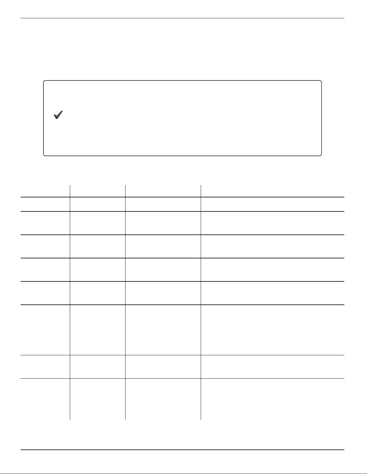
Sensor Health Table
The following error messages appear in the software and the data file when a sensor issue has been detected.
Abbreviation Data Quality ID Text Description
None 0 None Normal Data Quality
UC 1
FC 2
User Cal
Expired
Factory Cal
Expired
ERR 3 Unknown Error
WU 4
DIS 5
CAL 6
Sensor Warmup
Sensor
Warning
Sensor
Calibrating
OL 7 Sensor Missing
Parameter measured without errors
using an expired user calibration.
Parameter measured without errors
using an expired factory calibration.
Parameter measured with error,
sentinel value supplied.
Sensor is warming up, sentinel
value supplied.
Parameter measured but does not
meet normal quality criteria. The
sensor has sustained moderate
damage, or the recommended
lifespan has been reached.
Sensor is calibrating, calibration
value supplied.
Sensor communication failed,
sentinel value supplied. Make sure
the sensor cap is installed and
properly seated.
27
Page 28
Appendix A - Communication Device
The Communication Device is an accessory product that can be used to calibrate and set up RDO probes.
Install and Open the Software
The Comm Kit Software must be installed on a computer before you connect to the probe.
Connect the Probe to the Communication Device
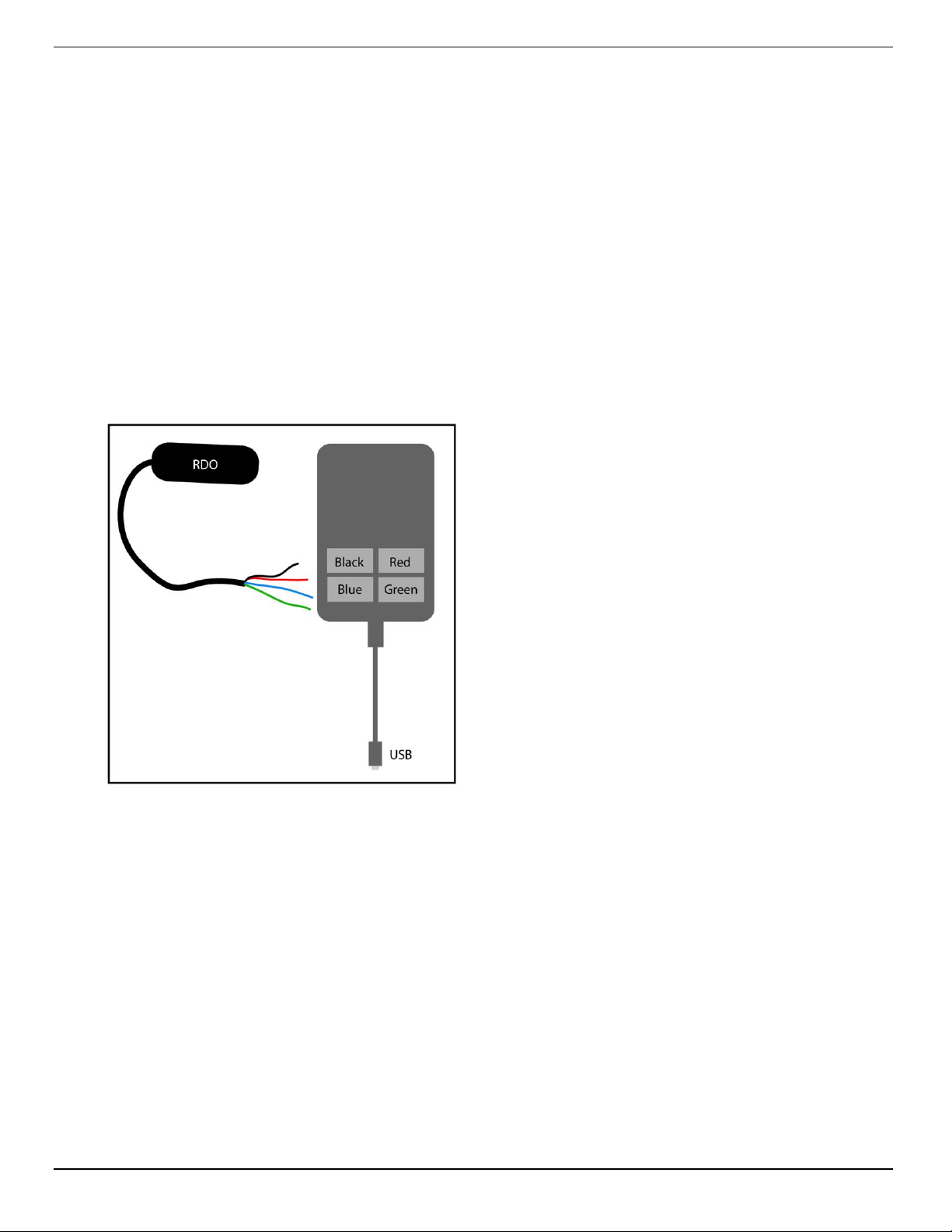
The Communication Device connects a stripped-and-tinned probe to a computer via USB connection.
1. Disconnect the instrument from the PLC.
2. The communication device includes an electrical connection diagram label. To attach the instrument to the
communication device, depress a lever and insert the appropriate wire in the location specified by the diagram.
3. Attach the USB connector to a USB port on the computer. Follow the directions provided in the Communication
Device Kit to set up the probe.
28
Page 29
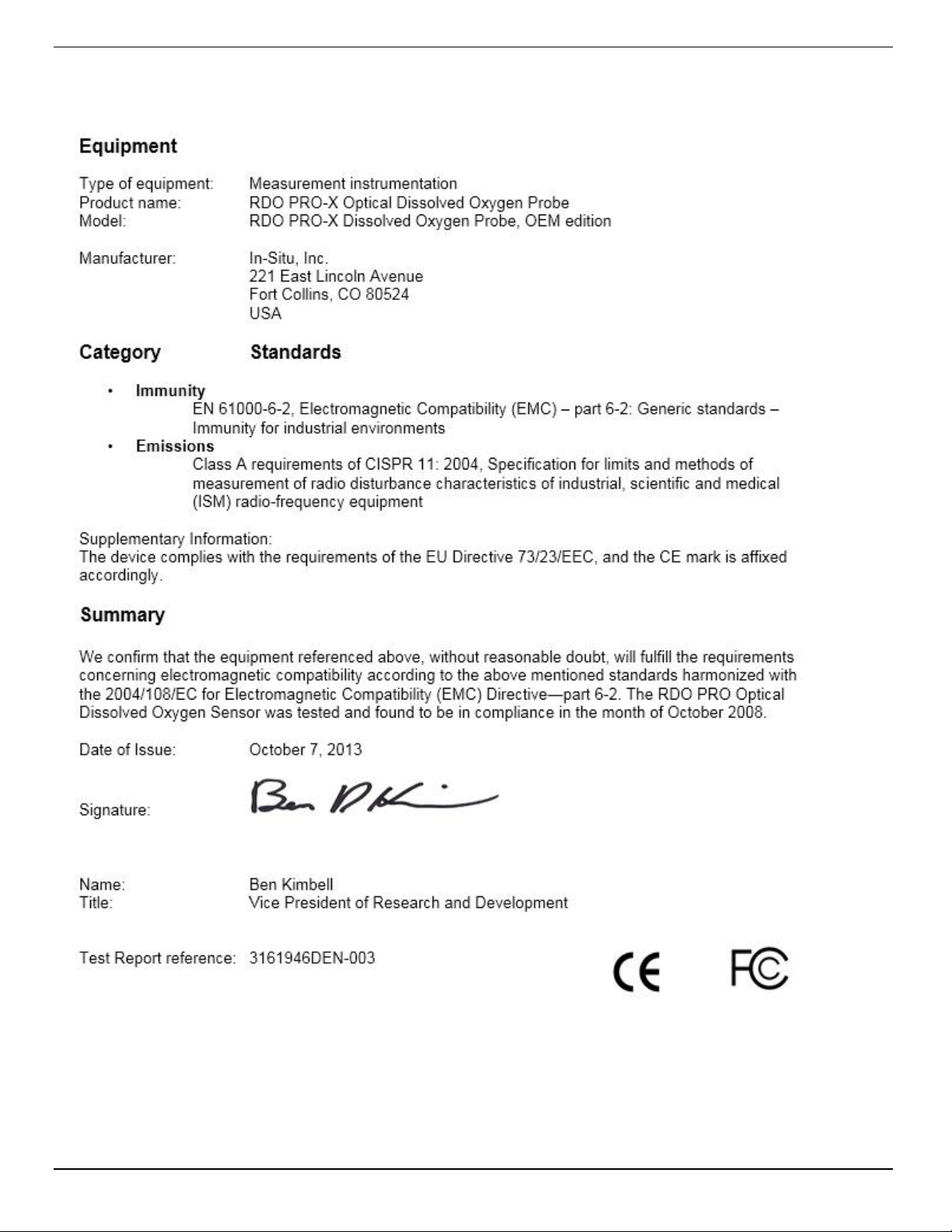
Declaration of Similarity
29
 Loading...