


User Guide
5.1 Channel Home Theater System
NS-HTIB51A

Contents
Introduction . . . . . . . . . . . . . . . . . . . . . . . . . . . . . . . . . . . . . . . . . . . . . . . . . . . . .1
Safety information . . . . . . . . . . . . . . . . . . . . . . . . . . . . . . . . . . . . . . . . . . . . . . .1
Ventilation . . . . . . . . . . . . . . . . . . . . . . . . . . . . . . . . . . . . . . . . . . . . . . . . . . . . . . 1
Power cord . . . . . . . . . . . . . . . . . . . . . . . . . . . . . . . . . . . . . . . . . . . . . . . . . . . . . . 1
Important safety instructions . . . . . . . . . . . . . . . . . . . . . . . . . . . . . . . . . . . . . 1
Precautions . . . . . . . . . . . . . . . . . . . . . . . . . . . . . . . . . . . . . . . . . . . . . . . . . . . . . . 2
Receiver components . . . . . . . . . . . . . . . . . . . . . . . . . . . . . . . . . . . . . . . . . . . .3
Receiver features . . . . . . . . . . . . . . . . . . . . . . . . . . . . . . . . . . . . . . . . . . . . . . . . 3
Package contents . . . . . . . . . . . . . . . . . . . . . . . . . . . . . . . . . . . . . . . . . . . . . . . . 3
Front controls . . . . . . . . . . . . . . . . . . . . . . . . . . . . . . . . . . . . . . . . . . . . . . . . . . . 3
Display . . . . . . . . . . . . . . . . . . . . . . . . . . . . . . . . . . . . . . . . . . . . . . . . . . . . . . . . . . 4
Back . . . . . . . . . . . . . . . . . . . . . . . . . . . . . . . . . . . . . . . . . . . . . . . . . . . . . . . . . . . . . 4
Subwoofer . . . . . . . . . . . . . . . . . . . . . . . . . . . . . . . . . . . . . . . . . . . . . . . . . . . . . . 4
Front, center, and surround speakers . . . . . . . . . . . . . . . . . . . . . . . . . . . . . 5
Remote control . . . . . . . . . . . . . . . . . . . . . . . . . . . . . . . . . . . . . . . . . . . . . . . . . . 5
Setting up your home theater system . . . . . . . . . . . . . . . . . . . . . . . . . . . . .5
Finding a location for your home theater system . . . . . . . . . . . . . . . . . . 5
Placing your speakers . . . . . . . . . . . . . . . . . . . . . . . . . . . . . . . . . . . . . . . . . . . . 6
Connecting your speakers to the receiver . . . . . . . . . . . . . . . . . . . . . . . . . 6
Connecting devices . . . . . . . . . . . . . . . . . . . . . . . . . . . . . . . . . . . . . . . . . . . . . . 7
Using rubber feet/pads for more stable speakers . . . . . . . . . . . . . . . . . 11
Wall mounting your speakers . . . . . . . . . . . . . . . . . . . . . . . . . . . . . . . . . . . 12
Installing batteries in the remote control . . . . . . . . . . . . . . . . . . . . . . . . 12
Using the remote control . . . . . . . . . . . . . . . . . . . . . . . . . . . . . . . . . . . . . . . 12
Using the Audyssey 2EQ® room correction and speaker setup . . . . 12
Operating your receiver . . . . . . . . . . . . . . . . . . . . . . . . . . . . . . . . . . . . . . . . 14
Turning your receiver on and off . . . . . . . . . . . . . . . . . . . . . . . . . . . . . . . . 14
Understanding basic operations . . . . . . . . . . . . . . . . . . . . . . . . . . . . . . . . . 14
Listening to your receiver . . . . . . . . . . . . . . . . . . . . . . . . . . . . . . . . . . . . . . 15
Listening to the radio . . . . . . . . . . . . . . . . . . . . . . . . . . . . . . . . . . . . . . . . . . . 15
Presetting FM or AM stations . . . . . . . . . . . . . . . . . . . . . . . . . . . . . . . . . . . . 16
Using the listening modes . . . . . . . . . . . . . . . . . . . . . . . . . . . . . . . . . . . . . . 16
Using advanced setup . . . . . . . . . . . . . . . . . . . . . . . . . . . . . . . . . . . . . . . . . . 19
Using on-screen setup menus . . . . . . . . . . . . . . . . . . . . . . . . . . . . . . . . . . . 19
Setting up HDMI input (HDMI Input menu) . . . . . . . . . . . . . . . . . . . . . . 19
Setting up Component input (Component menu) . . . . . . . . . . . . . . . 19
Setting up Digital Audio (Digital Audio menu) . . . . . . . . . . . . . . . . . . . 19
Configuring speakers (Sp Config menu) . . . . . . . . . . . . . . . . . . . . . . . . . 20
Setting speaker distance (Sp Distance menu) . . . . . . . . . . . . . . . . . . . . 20
Setting the level calibration (Level Cal menu) . . . . . . . . . . . . . . . . . . . . 21
Adjusting the audio (Audio Adjust menu) . . . . . . . . . . . . . . . . . . . . . . . . 21
Naming inputs (Name Edit menu) . . . . . . . . . . . . . . . . . . . . . . . . . . . . . . . 22
Setting up HDMI (HDMI Setup menu) . . . . . . . . . . . . . . . . . . . . . . . . . . . . 23
Changing audio settings . . . . . . . . . . . . . . . . . . . . . . . . . . . . . . . . . . . . . . . . 24
Selecting a digital input signal format . . . . . . . . . . . . . . . . . . . . . . . . . . . 25
iii
www.insigniaproducts.com

Contents
Controlling other components . . . . . . . . . . . . . . . . . . . . . . . . . . . . . . . . . 26
Preprogrammed remote control codes . . . . . . . . . . . . . . . . . . . . . . . . . . 26
Using the remote control to control other components . . . . . . . . . . 26
Remote control codes . . . . . . . . . . . . . . . . . . . . . . . . . . . . . . . . . . . . . . . . . . . 27
Maintaining . . . . . . . . . . . . . . . . . . . . . . . . . . . . . . . . . . . . . . . . . . . . . . . . . . . . 30
Troubleshooting . . . . . . . . . . . . . . . . . . . . . . . . . . . . . . . . . . . . . . . . . . . . . . . 30
Specifications . . . . . . . . . . . . . . . . . . . . . . . . . . . . . . . . . . . . . . . . . . . . . . . . . . 32
Amplifier section . . . . . . . . . . . . . . . . . . . . . . . . . . . . . . . . . . . . . . . . . . . . . . . 32
Video section . . . . . . . . . . . . . . . . . . . . . . . . . . . . . . . . . . . . . . . . . . . . . . . . . . . 32
Tuner section . . . . . . . . . . . . . . . . . . . . . . . . . . . . . . . . . . . . . . . . . . . . . . . . . . . 32
General section . . . . . . . . . . . . . . . . . . . . . . . . . . . . . . . . . . . . . . . . . . . . . . . . . 32
Subwoofer . . . . . . . . . . . . . . . . . . . . . . . . . . . . . . . . . . . . . . . . . . . . . . . . . . . . . 32
Front speakers . . . . . . . . . . . . . . . . . . . . . . . . . . . . . . . . . . . . . . . . . . . . . . . . . . 32
Center speaker . . . . . . . . . . . . . . . . . . . . . . . . . . . . . . . . . . . . . . . . . . . . . . . . . 33
Surround speakers . . . . . . . . . . . . . . . . . . . . . . . . . . . . . . . . . . . . . . . . . . . . . . 33
Legal notices . . . . . . . . . . . . . . . . . . . . . . . . . . . . . . . . . . . . . . . . . . . . . . . . . . . 34
Dolby TrueHD . . . . . . . . . . . . . . . . . . . . . . . . . . . . . . . . . . . . . . . . . . . . . . . . . . 34
DTS HD™ . . . . . . . . . . . . . . . . . . . . . . . . . . . . . . . . . . . . . . . . . . . . . . . . . . . . . . . 34
HDMI® . . . . . . . . . . . . . . . . . . . . . . . . . . . . . . . . . . . . . . . . . . . . . . . . . . . . . . . . . . 34
AUDYSSEY 2EQ™ . . . . . . . . . . . . . . . . . . . . . . . . . . . . . . . . . . . . . . . . . . . . . . . . 34
One-year limited warranty . . . . . . . . . . . . . . . . . . . . . . . . . . . . . . . . . . . . . . 35
www.insigniaproducts.com
iv

Contents
v
www.insigniaproducts.com
Insignia NS-HTIB51A
5.1 Channel Home Theater System
Introduction
Congratulations on your purchase of a high-quality
Insignia product. Your NS-HTIB51A represents the
state of the art in home theater system design and
is designed for reliable and trouble-free
performance.
WARNING:
TO REDUCE THE RISK OF FIRE OR ELECTRIC
SHOCK, DO NOT EXPOSE THIS APPARATUS TO
RAIN OR MOISTURE.
CAUTION:
TO REDUCE THE RISK OF ELECTRIC SHOCK,
DO NOT REMOVE COVER (OR BACK). NO
USER-SERVICEABLE PARTS INSIDE. REFER
SERVICING TO QUALIFIED SERVICE
PERSONNEL.
Ventilation
Caution
Do not block any ventilation openings. Install in
accordance with these instructions.
Slots and openings in the cabinet are provided for
ventilation and to ensure reliable operation of your
system and to protect it from over-heating.
The openings should never be blocked by placing
your system on a bed, sofa, rug, or other similar
surface. This system should not be placed in a built-in
installation such as a bookcase or rack unless correct
ventilation is provided or these instructions have
been adhered to.
Power cord
Caution
We recommend that most appliances be placed
upon a dedicated circuit—a single outlet circuit
which powers only that appliance and has no
additional outlets or branch circuits. Check the
specification page of this manual for power
requirements.
Do not overload wall outlets. Overloaded wall
outlets, loose or damaged wall outlets, extension
cords, frayed power cords, or damaged or cracked
wire insulation are dangerous. Any of these
conditions could result in electric shock or fire.
Periodically examine the power cord. If its
appearance indicates damage or deterioration,
unplug it, discontinue use of your system, and have
the cord replaced with an exact replacement part by
an authorized service provider.
Protect the power cord from physical or mechanical
abuse, such as being twisted, kinked, pinched, closed
in a door, or walked upon. Pay particular attention to
plugs, wall outlets, and the point where the cord exits
your receiver.
To disconnect power from the outlet, pull out the
plug. When installing your system, make sure that the
plug is easily accessible.
Safety information
WARNING
RISK OF ELECTRIC SHOCK
DO NOT OPEN
The lightning flash with arrowhead symbol, within an
equilateral triangle, is intended to alert the user to the
presence of uninsulated “dangerous voltage” within
the product’s enclosure that may be of sufficient
magnitude to constitute a risk of electric shock to
persons.
The exclamation point within an equilateral triangle is
intended to alert the user to the presence of important
operating and maintenance (servicing) instructions in
the literature accompanying the appliance.
Important safety instructions
1 Read these instructions.
2 Keep these instructions.
3 Heed all warnings.
4 Follow all instructions.
5 Do not use this apparatus near water.
6 Clean only with dry cloth.
7 Do not block any ventilation openings. Install in
accordance with the manufacturer’s
instructions.
8 Do not install near any heat sources such as
radiators, heat registers, stoves, or other
apparatus (including amplifiers) that produce
heat.
9 Do not defeat the safety purpose of the
polarized or grounding-type plug. A polarized
plug has two blades with one wider than the
other. A grounding type plug has two blades
and a third grounding prong. The wide blade or
the third prong are provided for your safety. If
the provided plug does not fit into your outlet,
consult an electrician for replacement of the
obsolete outlet.
10 Protect the power cord from being walked on or
pinched particularly at plugs, convenience
receptacles, and the point where they exit from
the apparatus.
11 Only use attachments/accessories specified by
the manufacturer.
AVIS
RISQUE DE CHOC ELECTRIQUE
NE PAS
OUVRIR
www.insigniaproducts.com
1

Insignia NS-HTIB51A 5.1 Channel Home Theater System
PORTABLE CART WARNING
S3125A
12 Use only with the cart,
13 Unplug this apparatus during lightning storms
14 Refer all servicing to qualified service personnel.
15 Damage Requiring Service
16 Object and Liquid Entry
17 Batteries
18 If you install the apparatus in a built-in
stand, tripod, bracket, or
table specified by the
manufacturer, or sold with
the apparatus. When a cart
is used, use caution when
moving the cart/apparatus
combination to avoid injury
from tip-over.
or when unused for long periods of time.
Servicing is required when the apparatus has
been damaged in any way, such as
power-supply cord or plug is damaged, liquid
has been spilled or objects have fallen into the
apparatus, the apparatus has been exposed to
rain or moisture, does not operate normally, or
has been dropped.
Unplug the apparatus from the wall outlet and
refer servicing to qualified service personnel
under the following conditions:
• When the power-supply cord or plug is
damaged,
• If liquid has been spilled, or objects have fallen
into the apparatus,
• If the apparatus has been exposed to rain or
water,
• If the apparatus does not operate normally by
following the operating instructions. Adjust
only those controls that are covered by the
operating instructions as an improper
adjustment of other controls may result in
damage and will often require extensive work
by a qualified technician to restore the
apparatus to its normal operation,
• If the apparatus has been dropped or
damaged in any way, and
• When the apparatus exhibits a distinct change
in performance this indicates a need for
service.
• Never push objects of any kind into the
apparatus through openings as they may
touch dangerous voltage points or short-out
parts that could result in a fire or electric
shock.
• The apparatus shall not be exposed to
dripping or splashing and no objects filled
with liquids, such as vases shall be placed on
the apparatus.
• Don’t put candles or other burning objects on
top of this unit.
Always consider the environmental issues and
follow local regulations when disposing of
batteries.
installation, such as a bookcase or rack, ensure
that there is adequate ventilation.
Leave 20 cm (8") of free space at the top and
sides and 10 cm (4") at the rear. The rear edge of
the shelf or board above the apparatus shall be
set 10 cm (4") away from the rear panel or wall,
creating a flue-like gap for warm air to escape.
Precautions
1 Recording copyrighted material—Unless it’s for
personal use only, recording copyrighted
material is illegal without the permission of the
copyright holder.
2 AC fuse—The AC fuse inside the unit is not
user-serviceable. If you cannot turn on the unit,
contact your Insignia dealer.
3 Care—Occasionally you should dust the unit all
over with a soft cloth. For stubborn stains, use a
soft cloth dampened with a weak solution of
mild detergent and water. Dry the unit
immediately afterwards with a clean cloth.
Don’t use abrasive cloths, thinners, alcohol, or
other chemical solvents, because they may
damage the finish or remove the panel lettering.
4 Power
Warni ng
AC outlet voltages vary from country to country.
Make sure that the voltage in your area meets
the voltage requirements printed on the unit’s
rear panel (e.g., AC 230 V, 50 Hz or AC 120 V, 60
Hz).
The power cord plug is used to disconnect this
unit from the AC power source. Make sure that
the plug is readily operable (easily accessible) at
all times.
Pressing ON/STANDBY to select Standby mode
does not fully shutdown the unit. If you do not
intend to use the unit for an extended period,
remove the power cord from the AC outlet.
5 Preventing Hearing Loss
Caution
6 Batteries and heat exposure
Warni ng
7 Never touch this unit with wet hands—Never
handle this unit or its power cord while your
hands are wet or damp. If water or any other
liquid gets inside this unit, have it checked by
your Insignia dealer.
8 Handling notes
• If you need to transport this unit, use the
original packaging to pack it how it was when
you originally bought it.
• Do not leave rubber or plastic items on this
unit for a long time, because they may leave
marks on the case.
• This unit’s top and rear panels may get warm
after prolonged use. This is normal.
Before plugging in the unit for the first time, read the
following section carefully.
Excessive sound pressure from earphones and
headphones can cause hearing loss.
Batteries (battery pack or batteries installed) shall not
be exposed to excessive heat as sunshine, fire or the
like.
2
www.insigniaproducts.com
Insignia NS-HTIB51A 5.1 Channel Home Theater System
Receiver components
Receiver features
• 110 Watts/Channel @ 6 ohms
• Audyssey 2EQ to Correct Room Acoustic Problems
• Audyssey Dynamic EQ for Loudness Correction
• Audyssey Dynamic Volume to Maintain Optimal
Listening Level and Dynamic Range
• HDMI (Ver.1.4 with Audio Return Channel, 3D),
Deep-Color, x.v.Color, Lip Sync, DTS-HD Master
Audio, DTS-HD High Resolution Audio, Dolby
TrueHD, Dolby Digital Plus, DSD and Multi-CH
PCM
• 3 HDMI Inputs and 1 Output
• 3 Digital Inputs (2 Optical/1 Coaxial)
• Component Video Switching (2 Inputs/1 Output)
• Banana Plug-Compatible Speaker Posts
• 40 FM/AM Presets
• H.C.P.S. (High Current Power Supply) Massive High
Power Transformer
•Direct Mode
• 192 kHz/24-bit D/A Converters
• Powerful and Highly Accurate 32-bit Processing
DSP
• Crossover Adjustment
(40/50/60/80/100/120/150/200 Hz)
• A/V Sync Control Function (up to 100 ms)
•On-Screen Display via HDMI
* “x.v.Color” is a trademark of Sony Corporation.
Package contents
• Receiver
•2 Front speakers
•1 Center speaker
• 2 Surround speakers
•1 Subwoofer
•Remote control
• 2 x AA batteries
• FM antenna
• AM antenna
• Speaker setup microphone
• Color labels for speaker cables
•Speaker cables:
•11 ft. x 3
•26 ft. x 2
•RCA cable 10 ft. x 1
• 20 rubber spacers for speakers
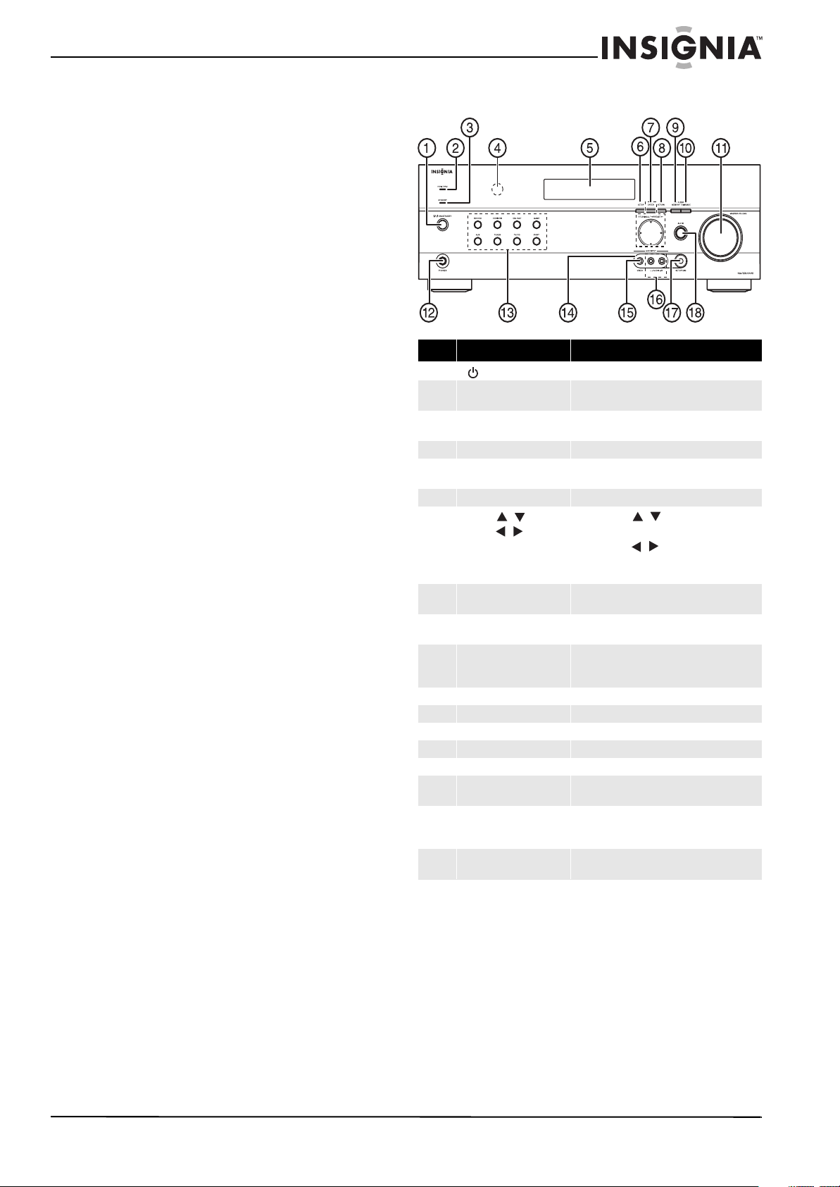
Front controls
Item Description Function
1
|/ ON/STANDBY button
2 HDMI THRU indicator Lights when the HDMI pass-through function is
3 STANDBY indicator Lights red when your stereo receiver is in
4 Remote control sensor Receives the signal from the remote control.
5 Display See “Display” on page 4 for additional
6 SETUP button Press to open the on-screen menus.
7
TUNING /
PRESET /
ENTER
8 RETURN button In menu mode, press to return to the main
9 MEMORY button Press to save a radio station preset. Press with
10 TUNING MODE button Press to turn on the receiver tuning mode and
11 MASTER VOLUME knob Turn to increase or decrease the volume.
12 Headphone jack Plug your headphones into this jack.
13 Input selector buttons Press to select the input signal source you want.
14 Protective cap Remove when using jack.
15 AUX INP UT VIDEO jack Plug an external video source into this jack.
16 AUX INPUT AUDIO L/R
jacks
17 SETUP MIC jack Plug the Audyssey setup microphone into this
18 AUDIO button Press to access audio settings. See “Changing
Press to turn on your stereo receiver.
activated in standby mode.
standby mode.
information.
Press TUNING / to tune the radio to the
next or previous station.
Press PRESET / to tune the radio to the
next or previous station preset.
Press ENTER to confirm a selec tion.
menu.
the TUNING MODE button to clear presets.
listen to the radio. Press with the MEMORY
button to clear presets.
Plug an external sound source into this jack.
jack. See “Using the Audyssey 2EQ® room
correction and speaker setup” on page 12.
audio settings” on page 24.
www.insigniaproducts.com
3

Insignia NS-HTIB51A 5.1 Channel Home Theater System
Front
Back
Display
Back
Subwoofer
# Indicator
1 Audio input indicator
2 Listening mode indicator
3 Audyssey indicators
4 Tuning indicators
5 SLEEP indicator
6 MUTING indicator
7 DIGITAL display
# Description Function
1 DIGITAL IN jacks Plug the optical digital cable from a game (1) or
2 COMPONENT video jacks Plug the cables from a component video source
3 HDMI jacks Plug the HDMI signal input cable from a GAME
4 ANTENNA connectors Connect a 75 ohm FM antenna to the coaxial
5 MONITOR OUT V (Video) Connect this jack to a TV monitor.
6 FRONT SPEAKERS Connect the front speakers to these jacks.
7 AC power cord Plug this cord into an AC power outlet.
8 Composite Video and
9 SUBWOOFER Connect the subwoofer to this jack.
SURROUND SPEAKERS
CENTER SPEAKER
Audio L/R jacks
TV/CD (2) into the upper jacks, or the coaxial
digital cable from a BD/DVD into the lower jack.
into the #1 (BD/DVD) or #2 (CBL/SAT) jacks.
Plug the cables to a component video monitor into
the OUT jacks.
The jacks are color coded (red, green, and blue) to
correspond to the cable connectors.
(IN3), cable/satellite box (IN2), or a BD/DVD player
(IN1).
Plug the HDMI output signal cable to a TV or
monitor into the OUT jack.
connector or an AM loop antenna to the wire
connectors.
Connect the left and right surround speakers and
the center speaker to these connectors.
Plug the composite video and audio L/R output
cables from the indicated devices into these jacks.
For video recording, plug the composite video and
audio L/R input cables to a VCR or DVR into the
OUT jacks
# Description Function
1 Standby/On indicator Red: Subwoofer in standby mode
Blue: Subwoofer on
With the auto standby function, the subwoofer
automatically turns on when an input signal is
detected in standby mode. When there is no
input signal, the subwoofer automatically
enters standby mode.
Note: The auto standby function turns the subwoofer
on when the input signal exceeds a certain level. If the
auto standby function does not work reliably, try
slightly increasing or decreasing the subwoofer output
level on the receiver
2 OUTPUT LEVEL control This control is used to adjust the volume of the
3 LINE INPUT jack This jack should be connected to the subwoofer
subwoofer.
pre-out on the AV receiver with the supplied
RCA cable.
4
www.insigniaproducts.com
Insignia NS-HTIB51A 5.1 Channel Home Theater System
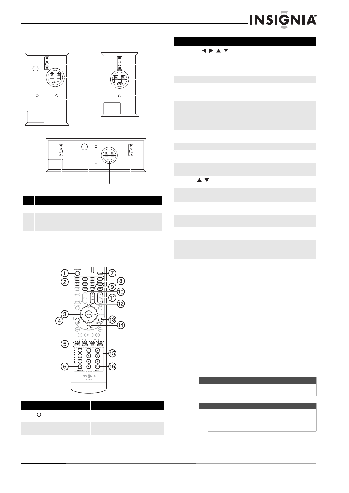
a
b
c
a
b
c
Front speake rs
Rear speakers
Center speaker
Front, center, and surround speakers
SC-51A
abc
# Description Function
1 Keyhole slots Used to wall-mount the speakers.
2 Speaker terminals These push terminals are for connecting the
speaker to the receiver with the supplied
speaker cables.
3 Threaded Inserts These threaded inserts are for Init®-Home
Theater Speaker Mounts NT-SWM series.
Remote control
Item Description Function
3
ENTER ///
TUNING+/–
4 SETUP button Press to open the on-screen menus.
5 LISTENING MODE buttons Press to select the listening mode you want.
6 D.T UN
DIMMER
7 DISPLAY button Press repeatedly to cycle through the
8 RECEIVER button Press to control the receive r.
9 MUTING button Press to mute the sound output from the
10 TUNE MODE button Press to toggle between auto and manual
11
VOL / buttons
12 CH +/– buttons
ALBUM
13 RETURN button In menu mode, press to return to the main
14 AUDIO button Press to access audio settings. See
15 Number buttons Press to enter a preset number or to
16 SLEEP/CLR button Press repeatedly to select the sleep timer
Press the arrow keys to navigate through the
on-screen menus. Press ENTER to confirm a
selection or setting.
In tuning mode, press to tune to the next
(TUNING+) or previous (TUNING–) station.
See “Using the listening modes” on page 16
for additional information.
In tuner mode, press D.TUN , then the
number buttons to tune directly to a
frequency.
Press DIMMER to adjust the brightness of
the display.
available input source information.
receiver.
tuning modes.
Press to increase or decrease the sound
volume.
In tuner mode, press to go to the next or
previous preset channel.
menu.
“Changing audio settings” on page 24.
manually tune the radio.
duration.
In menu mode, press to clear an entry.
Item Description Function
1 ON/STANDBY button Press to turn the power on to your receiver.
2 Remote mode input selector
buttons
Press again to go to standby mode.
Press to directly select your receiver input
source.
Setting up your home theater system
Finding a location for your home theater system
• Install your home theater system on a stable flat
surface. Position your receiver so that it has a
direct line of sight to the remote control.
• Do not expose your system to extremes of
temperature or humidity.
• Avoid placing your system on a hot surface such
as on top of other hot running equipment. Make
sure that there is adequate ventilation to your
system.
Caution
Do not install the receiver in a confined space such as
a bookcase.
Caution
Connect the AC cord only after the speakers,
antenna, and all optional equipment have been
connected. Never make or change any
connections with the power turned on.
www.insigniaproducts.com
5
Insignia NS-HTIB51A 5.1 Channel Home Theater System
Red line
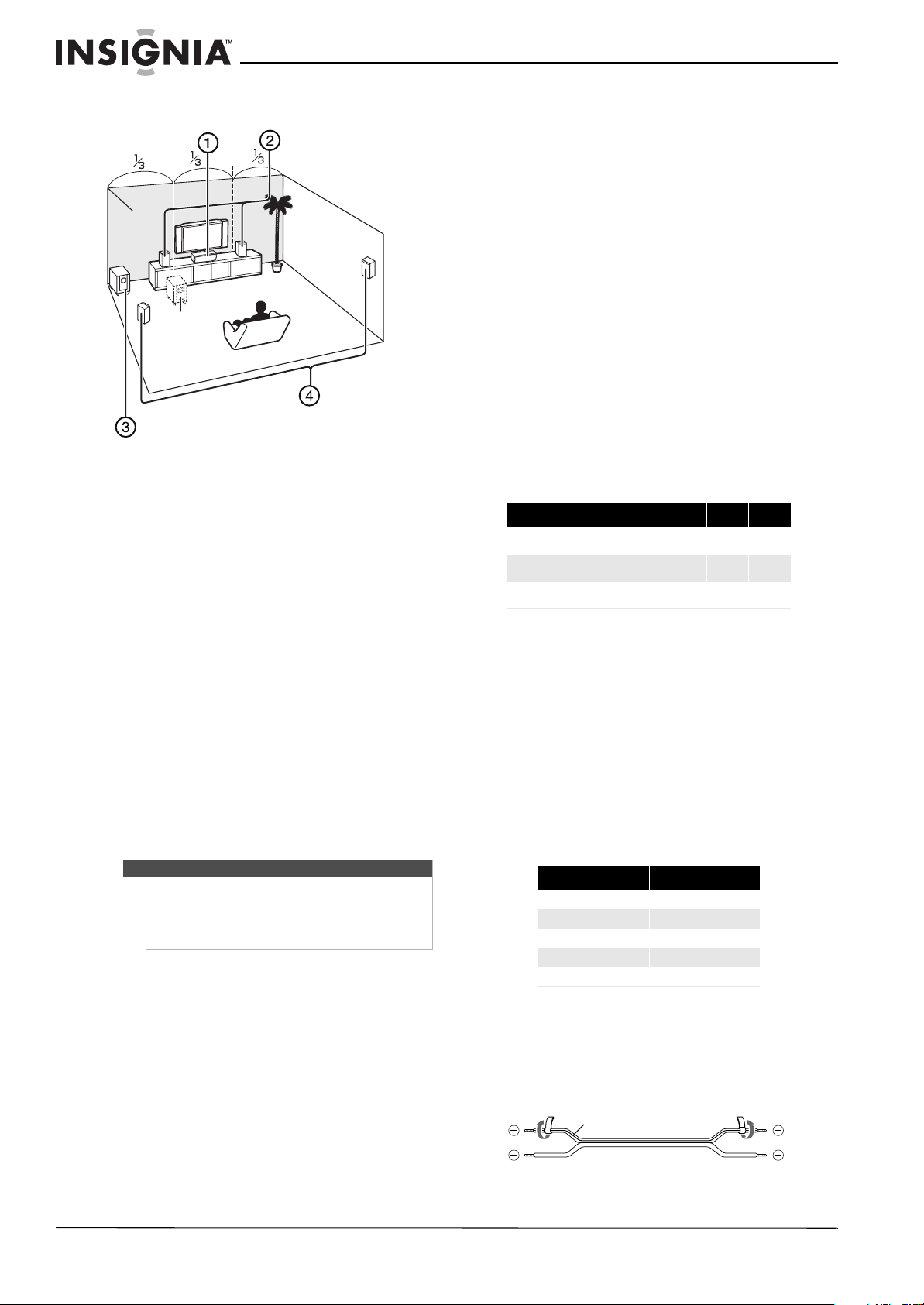
Placing your speakers
1 - Center speaker
This speaker enhances the front speakers, making
sound movements distinct and providing a
full-sound image. In movies it is used mainly for
dialog. Position it close to your TV facing forward at
about ear level, or at the same height as the front
speakers.
2 - Front speakers
These provide the overall sound. Their role in a
home theater system is to provide a solid anchor for
the sound image. They should be positioned facing
the listener at about ear level, and equidistant from
the TV. Angle them inward so as to create a triangle,
with the listener at the apex.
3 - Subwoofer
The subwoofer handles the bass sounds of the LFE
(Low-Frequency Effects) channel. The volume and
quality of the bass output from your subwoofer will
depend on its position, the shape of your listening
room, and your listening position. In general, a
good bass sound can be obtained by installing the
subwoofer in a front corner, or at one-third the
width of the wall, as shown.
Tip
To find the best position for your subwoofer, while
playing a movie or some music with good bass,
experiment by placing your subwoofer at various
positions within the room, and choose the one that
provides the most satisfying results.
4 - Surround speakers
These speakers are used for precise sound
positioning and to add realistic ambience. Position
them at the sides of the listener, or slightly behind,
about two to three feet (60 to 100 cm) above ear
level. Ideally they should be equidistant from the
listener.
Speaker precautions
• The speaker cabinets are made out of wood and
are therefore sensitive to extreme temperatures
and humidity. Do not put them in locations
subject to direct sunlight or in humid places, such
as near an air conditioner, humidifier, bathroom,
or kitchen.
• Do not put water or other liquids close to the
speakers. If liquid is spilled on the speakers, they
may be damaged.
• Speakers should only be placed on sturdy, flat
surfaces that are free from vibration. Putting them
on uneven or unstable surfaces, where they may
fall and cause damage, affects the sound quality.
• The subwoofer is designed to be used in the
upright vertical position only. Do not use it in the
horizontal or tilted position.
• If the subwoofer is placed near a turntable, CD
player, or Blu-ray Disc/DVD player, howling or
slipping of the sound may occur. To prevent this,
move the unit away from the turntable, CD player,
or Blu-ray Disc/DVD player, or lower the
subwoofer’s output level.
Connecting your speakers to the receiver
Speaker configuration
The following table indicates the channels you
should use depending on the number of speakers
that you have. For 5.1-channel surround-sound
playback, you need five speakers and a powered
subwoofer.
Number of channels 2 3 4 5
Front speakers
Center speaker
Surround speakers
No matter how many speakers you use, a powered
subwoofer is recommended for a really powerful
and solid bass.
To get the best from your surround sound system,
you need to set the speaker settings. You can do
this automatically (see “Using the Audyssey 2EQ®
room correction and speaker setup” on page 12, or
manually (see “Configuring speakers (Sp Config
menu) on page 20).
Attaching the speaker cable labels
The AV receiver’s positive (+) speaker terminals are
all red. (The negative (–) speaker terminals are all
black.)
Speaker Color
Front left White
Front right Red
Center Green
Surround left Blue
Surround right Gray
The supplied speaker cable labels are also
color-coded. You should attach them to the positive
(+) side of each speaker cable in accordance with
the table above. Then all you need to do is to match
the color of each label to the corresponding
speaker terminal.
XXXX
X X
XX
6
www.insigniaproducts.com
Insignia NS-HTIB51A 5.1 Channel Home Theater System
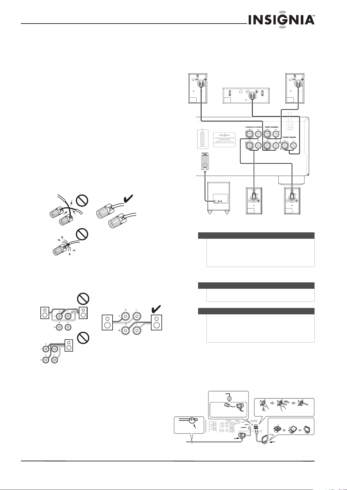
Front right speaker
Front left s peaker
Center speaker
Powered subwoofer
Surround right
speaker
Surround left
speaker
Thumbtac ks
Indoor FM antenna (supplied)
AM loop antenna (supplied)
Assembling the AM loop antenna
Push
Insert the plug
fully into the jack
Insert wire
Release
FM 75 Ohm
Speaker connection precautions
Read the following before connecting your
speakers:
• You can connect speakers with an impedance of
between 6 and 16 ohms. If you use speakers with
a lower impedance, and use the amplifier at high
volume levels for a long period of time, the
built-in amp protection circuit may be activated.
• Disconnect the power cord from the wall outlet
before making any connections.
• Pay close attention to speaker wiring polarity. In
other words, connect positive (+) terminals only
to positive (+) terminals, and negative (–)
terminals only to negative (–) terminals. If you get
them the wrong way around, the sound will be
out of phase and will sound unnatural.
• Unnecessarily long, or very thin speaker cables
may affect the sound quality and should be
avoided.
• Be careful not to short the positive and negative
wires. Doing so may damage the receiver.
• Make sure the metal core of the wire does not
have contact with the receiver’s rear panel. Doing
so may damage the receiver.
4 Press and hold the push-terminals on each
speaker and insert the speaker wire, then
release the push-terminal to secure the wire
(black wires go to the negative (–) terminals).
• Don’t connect more than one cable to each
speaker terminal. Doing so may damage the
receiver.
• Don’t connect one speaker to several terminals.
To connect the speaker cables:
1 Strip 1/2" to 5/8" (12 to 15 mm) of insulation
from the ends of the speaker cables, and twist
the bare wires tightly, as shown. (Supplied
speaker cables are already stripped.)
2 Loosen the speaker terminals on the receiver
and insert the speaker wires into the terminals
(black wires go to the negative (–) terminals).
The following illustration shows which speaker
should be connected to each pair of terminals.
3 Tighten the terminals to secure the wire.
Tips
• If you are using banana plugs, tighten the
speaker terminal before inserting the banana
plug.
• Do not insert the speaker wire directly into the
center hole of the speaker terminal.
Connecting devices
Warni ng
Do not plug the AC cord into the AC outlet until all
connections are completed.
Notes
• Be sure to observe the color coding when
connecting audio and speaker cords.
• Make connections firmly and correctly. Failure
to do this can cause loss of sound, add noise to
the sound, or damage your receiver.
Connecting the antenna
This section explains how to connect the supplied
indoor FM antenna and AM loop antenna.
The receiver won’t pick up any radio signals without
any antenna connected, so you must connect the
antenna to use the tuner.
www.insigniaproducts.com
7
Insignia NS-HTIB51A 5.1 Channel Home Theater System
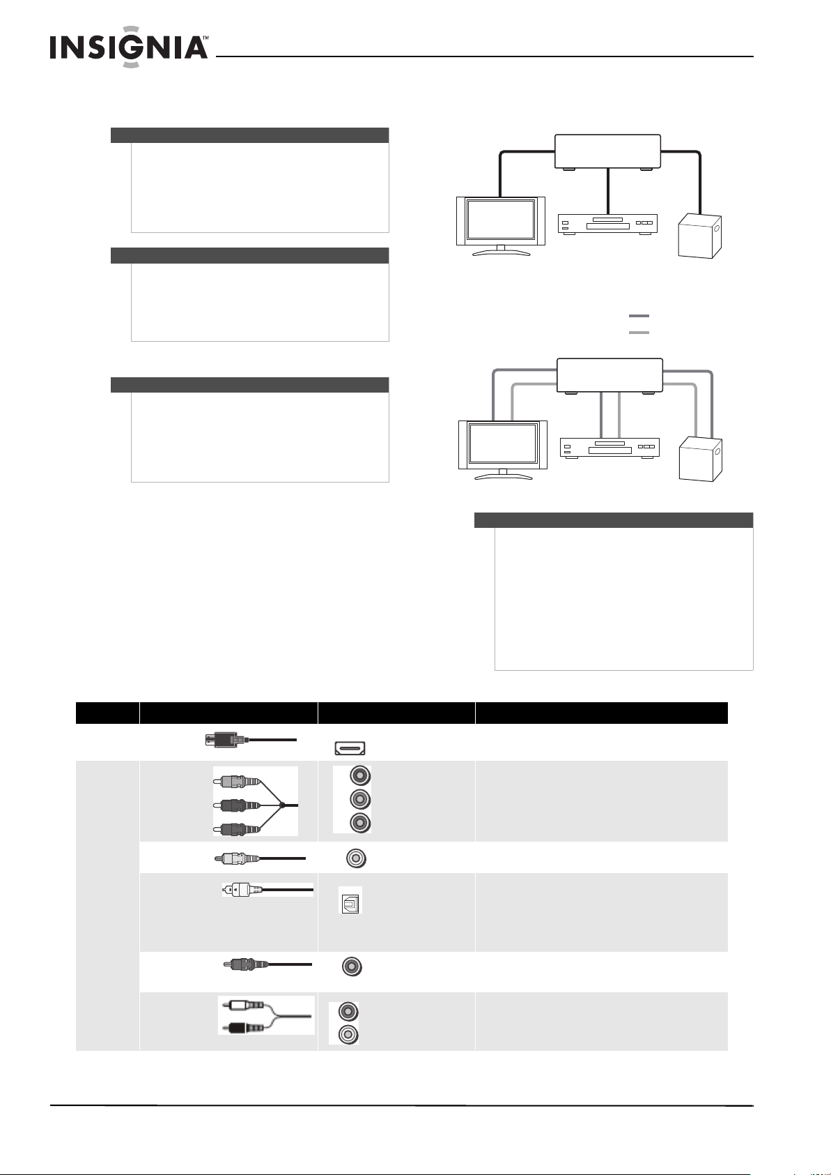
Receiver
TV or projector
Blu-ray disc/DVD player
Game console
TV or projector
Receiver
Blu-ray disc/DVD player
Game console
Video
Audio
Y
Pb/Cb
Pr/Cr
To connect the antennas:
1 Connect the FM antenna to your receiver.
Note
If you are using an indoor FM antenna, change the
position of the antenna until you get the best
reception of your favorite FM stations.
To improve reception, use a 75 Ω outdoor antenna
instead of an indoor antenna. Disconnect the
indoor antenna before replacing it with an outdoor
antenna.
Tip
Once your receiver is ready for use, you need to tune
into a radio station and position the antenna to
achieve the best possible reception.
If you cannot achieve good reception with the
supplied indoor FM antenna, try a commercially
available outdoor FM antenna instead.
2 Connect the AM loop antenna to the receiver.
Notes
Place the AM loop antenna as far as possible from the
receiver, television, speaker cords, and the AC cord.
Change the position of the antenna until you get the
best reception of your favorite AM stations.
To improve reception, use an outdoor AM antenna
instead of a loop AM antenna. Disconnect the indoor
antenna before replacing it with an outdoor antenna.
Connecting audio components
HDMI cable
Other cables
Notes
• Before making any AV connections, read the
• Don’t connect the power cord until you’ve
• Push plugs in all the way to make good
• To prevent interference, keep audio and video
AV cables and jacks
Signal Cable Jack Description
Video and
audio
Video
Audio
HDMI
Component video
Composite video Yellow
Optical digital audio
Coaxial digital audio
Analog audio (RCA)
HDMI
Y
Pb
Pr
Y
OPTICAL
DIGITAL
L
R
Green
Blue
Red
Orange
White
Red
HDMI connections can carry digital video and audio.
Component video separates the luminance (Y) and color difference
signals (PR, PB), providing the best picture quality (some TV
manufacturers label their component video sockets slightly differently).
Composite video is commonly used on TVs, VCRs, and other video
equipment.
Optical digital connections allow you to enjoy digital sound such
as PCM* or Dolby Digital. The audio quality is the same as
coaxial.
Note: The available sampling rate for PCM input signals is
32/44.1/48/88.2/96 kHz. Even 176.4/192 kHz is effective in case of the
HDMI connection.
Coaxial digital connections allow you to enjoy digital sound such as PCM*
or Dolby Digital. The audio quality is the same as optical.
Analog audio connections (RCA) carry analog audio.
manuals supplied with your AV components.
completed and double-checked all AV
connections.
connections (loose connections can cause noise
or malfunctions).
cables away from power cords and speaker
cables.
8
www.insigniaproducts.com
 Loading...