

FA575X
Mounting Holes
(4 p lac es)
to ex tern a l d ev ice s
via knockou ts
Wiring Knockouts
(4 places)
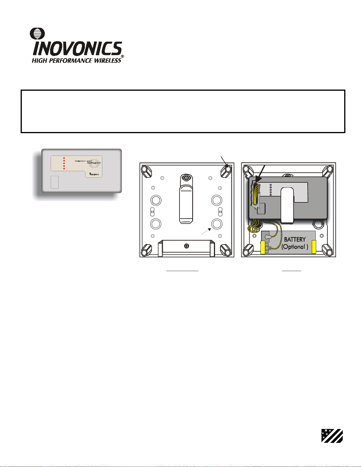
Installatio n
1) The enclosure can be
mounted with screws
inserted in the mounting
holes.
2) Flex the repeater clip slightly
to inse rt the rep eate r.
3) Flex the battery clip slightly
when inserting a battery.
Wiring
1) Wiring should be routed
thro u g h th e o val kn o c kout
in the repeater housing
base.
2) Wiring should exit the
enclosure through
knockouts in the enclosure
base.
High-Power Repeater
Exterior Installation Housing / without Transformer
®
Frequency Agile
Installation Instructions
Product Description
The FA575 is a sophisticated repeater in a weatherproof enclosure that receives, decodes, and re-transmits signals from Inovonics FA-series transmitters. It acts as a "range extender" for an y d ecodab l e I no vonics transmission . T he FA575 is intended
for quick and easy outdoor installation. (For applications that require neither the weatherproof enclosure nor the optional
backup battery, the repeater is available by itself as the FA570.)
AC POWE R
BACKUP POWER
DECODING
TRANSM ITTING
NOT ACTIV E
900MHz
Exam ple: Wiring from receiver
Specifications
Repeater housing dimensions: 6.38" x 3.60" x 1.10"
NEMA 4 enclosure dimensions: 7" x 7" x 3"
Enclosure + repeater weight: 20.7 oz.
(Optional) Backup battery: 12VDC
Repeater weight: 5.3 oz.
Power requirement: 14VAC @ 20VA
Low voltage th resh ol d: 1 0.5- 11.5VDC
© 2000 Inovonics Corporation. All rights reserved. Rev. 1.00 08/24/2000
Specifications
Receiver type: frequency-hopping spread spectrum
Operating frequency: 902-928 MHz
Operating Environment: 32°-140°F (0-60°C),
up to 95% relative humidity
(non-condensing)
REPEATER
MADE
IN USA
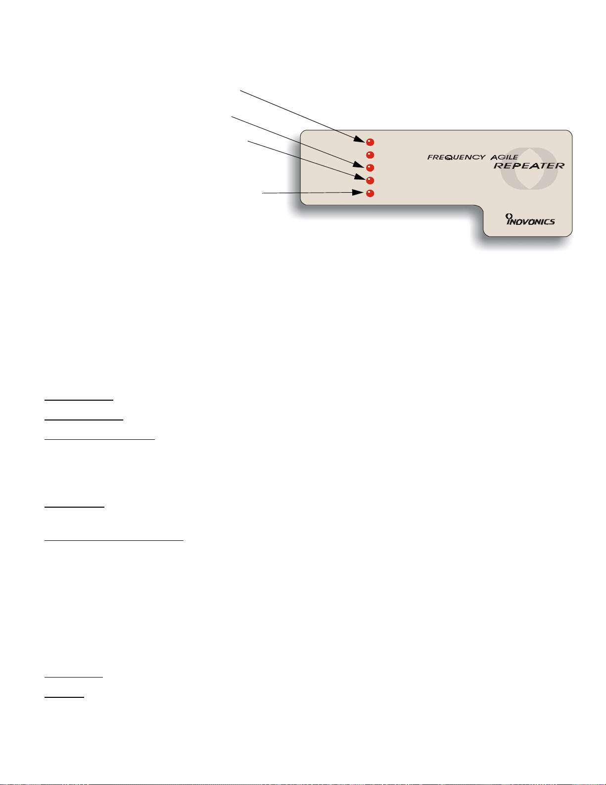
LED Indicators
• "AC POWER" and "BACKUP POWER" LEDs show
repeater power source.
• "DECODING" indicates that the repeater is
receiving RF energy.
• "TRANSMITTING" indicates that the repeater is
transmitting.
Note: The repeater does NOT decode while
transmitting.
NOT ACTIVE
•"
received an Inovonics transmission within its programmed check-in interval. It is "waiting" for
incoming traffic.
Note that when power is first applied or when the
repeater reset button is pressed, the "NOT ACTIVE"
LED will be on until the first valid transmitter message
is received.
This is a useful diagnostic indicator. In installations
where the repeater services many transmitter messages, illumination of the "NOT ACTIVE" LED might
indicate a repeater receiver problem.
Power supply
Backup battery
" means that the repeater has not
: A 14VAC transformer must be provided by the user to power the FA575.
: An optional 1.2AH battery can be mounted in the FA575 enclosure.
AC PO WER
BACKUP PO WER
DECODING
TRANSM ITTING
NOT ACTIVE
Operation
Low voltage detection
: The repeater will report low voltage if the supply voltage (either primary or backup)
causes its DC input voltage to drop below its low voltage threshold.
• AC power fai lure will not be reporte d direct ly—the sys tem will de tect ina ctivity if repeater power is off for
the duration of the supervision window. ‘
Supervision
: The repeater should be programmed to send check-in signals to the receiver, but can operate
unsupervised.
To program for supervision
: When programming the
system panel
to supervise the repeater, the repeater
point should be programmed as a 24-hour point. This is because the repeater may be processing signals from
24-hour points and should be given this same level of point status monitoring.
When programming the
repeater
for supervision, it is necessary to program the repeater to send check-in signals. All other programming options other than check-i n times (like normal ly open versus normal ly closed, and
presence or absence of EOL resistor) will be ignored. Repeater programming is accomplished by connecting a
programming cable to the programming header on the repeater, setting the appropriate check-in time when
prompted by the panel or receiver display device, and pressing the repeater’s Reset button. (See panel or
receiver programming or installation manuals for more specific information.)
Test Button
Tamper
: The Test Button is used only in unique OEM applications.
: Case tamper is provided.
FA575X Installation Instructions Page 2 of 4 Rev. 1.00 F575X_V1.FM 08/24/2000
 Loading...