

FA536
Locator
F reque ncy Agile
Interior Installation Housing
Installation Instructions
02803D
Product Description
The FA536 is a sophisticated locator designed and intended for use by qualified OEM customers. The FA536 receives, decodes,
and re-transmits signals from Inovonics FA-series transmitters. The FA536 is used to determine the approximate location of
roving transmitters. The FA536 appends location identification data to signals initiated within its reception range. User -cr eated
system software can then identify the general area from which the signal origin ated. The loca tor is not recommended for use in
multi-story bui l din gs .
The FA536 is intended for quick and easy indoor installati on. (Kits are available for outdoor installation.)
®
900MHz
AC POW ER
BACKUP POWER
(Optional ) Backup battery: 12VDC
DECODING
TRANSMITTING
NOT ACTIVE
Specifications
Housing dimensions: 6.38" x 3.60" x 1.10"
Weight: 6.9 oz.
Power requirement: 14VAC (power adapter provided)
Low voltage threshold: 10.5-11.5VDC
Maximum current: 75mA
Receiver type: frequency-hopping spread spectrum
Operating frequency: 902-928 MHz
Operating Environment: 32° to 140°F (0° to 60°C),
up to 95% relative humidity
(non-condensing)
MADE
© 2001 Inovonics Wireless Corporation 02803D 05/19/2004
IN USA
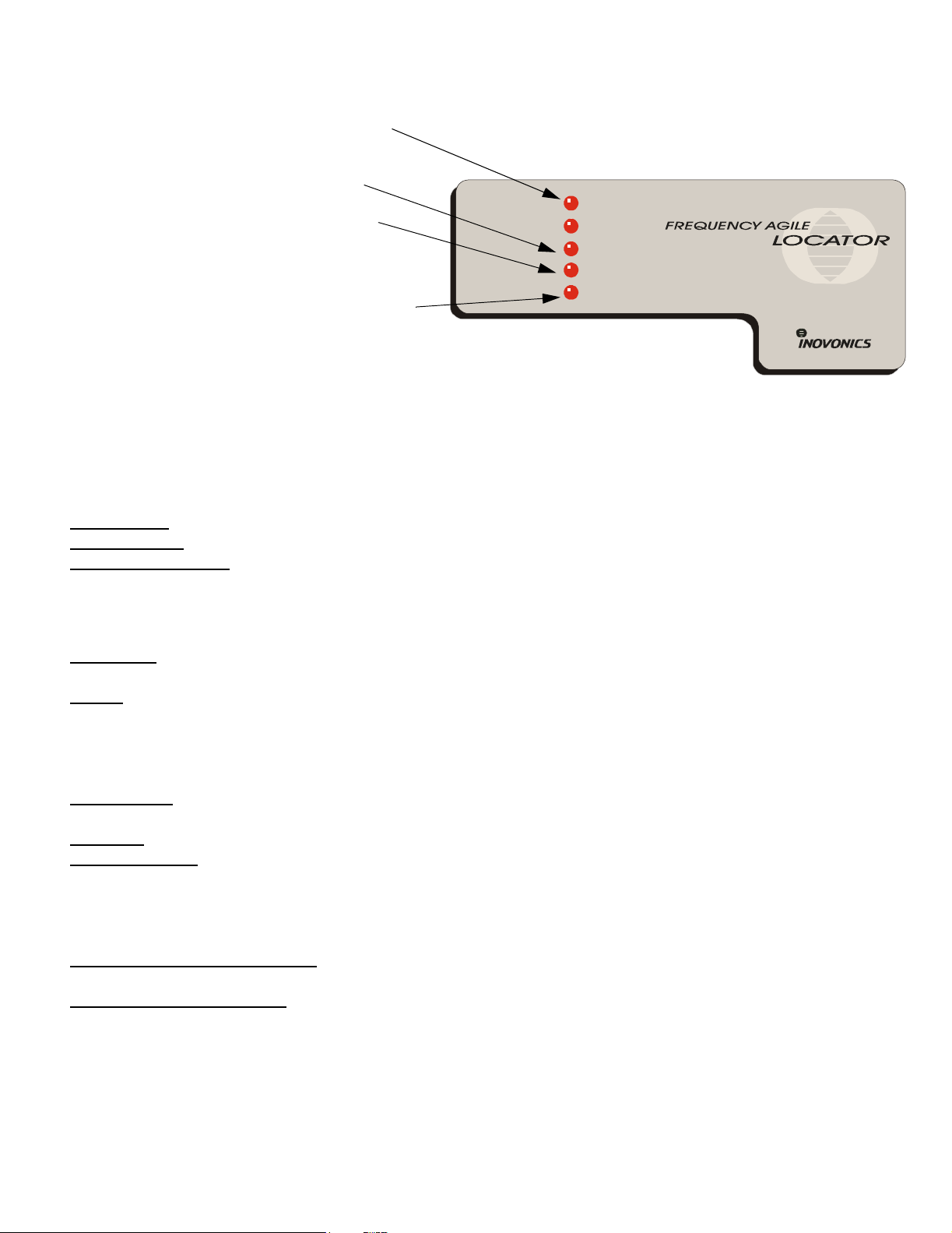
LED Indicators
• "AC POWER" and "BACKUP POWER" LEDs show
locator power source.
• "DECODING" indicates that the locator is receiving
RF energy.
• "TRANSMITTING" indicates that the locator is
transmitting.
Note: The locator does NOT decode while trans-
mitting.
• "NOT ACTIVE" means that the locator has not
received a transmission in a specified period. It is
"waiting" for incoming traffic.
Operation
AC POWER
BACKUP POWER
DECODING
TRANSMITTING
NOT ACTIVE
Power supply: A 14VAC transformer is provided with the FA536.
Backup battery
Low voltage detection
: An optional 1.2Ah battery (BAT603) can be mounted inside the the outdoor housing.
: The locator will report low voltage if the supply voltage (either primary or backup) drops into a
preset range.
• AC power failure will not be reported directly—the system receiver and PC will detect inactivity if locator
power is off for the duration of the supervision window.
Supervision: Locators should be programmed to send check-in signals to the receiver, but can operate unsupervised. The
system integrator will assess application conditions and will establish parameters for proper supervision.
Output
alarm signal (i.e., a sign al coming directly from a transmitter) , the open collector output will switch to a "low" state until
either the reset button on the locator is pressed, or the external reset terminal is shunted to ground. The output can be used
to activate annunciation or signalling equipment. Output reset occurs when the transmitter causing the alarm condition
restores (unless locator is factory-programmed to latch).
External reset
to reset the locator Output terminal.
Test mode
Tracking Jumper
alarm signals ONLY. In the "YES" position, data will also be appended to original supervisory (check-in) transmissions.
This permits rough position tracking of roving transmitters, but decreases the locator’s ability to receive alarm transmissions, especially in installations with hundreds of transmitters. (Locators are "busy" sending in supervisory data for significant portions of their duty cycles.)
External tamper / Auxiliary input
input whose activation will cause the FA536 to send a locating tamper transmission.
Locator Range Potentiometer
the locator coverage can be limited, providing better resolution of location. The Pot can be set from full sensitivity of 110dB (maximum re ceive range) to a mini mum sensitivity of -40 dB (minimum receive ran ge). Locators shou ld be mounted
in locations indicated by system designer. Sensitivity adjustments are necessary whenever replacing a locator.
: The FA536 will NOT repeat signals from oth er loca tors or other repeat ers. Wh en an FA536 receives a "fir sthan d"
: A circuit c onnecting the reset terminal with the ground terminal via a N/O momentary switch can be used
: Pressing the Test button will cause the locator to transmit a current status message until the button is released.
: When the Track jumper is in the "NO" position, the locator will append identification data to firsthand
: This terminal can be used to connect a tamper switch outside the case, or to a N/C
: The Locator Range Pot is provided on the locator to allow the receiver to be desensed, so
FA536 Installation Instructions Page 2 of 4 02803D 05/19/2004
 Loading...