

Frequency Agile
®
900MHz
16 Point Receiver Expander
for Radionics 2000 Series Control Panels
Installation Instructions
02793
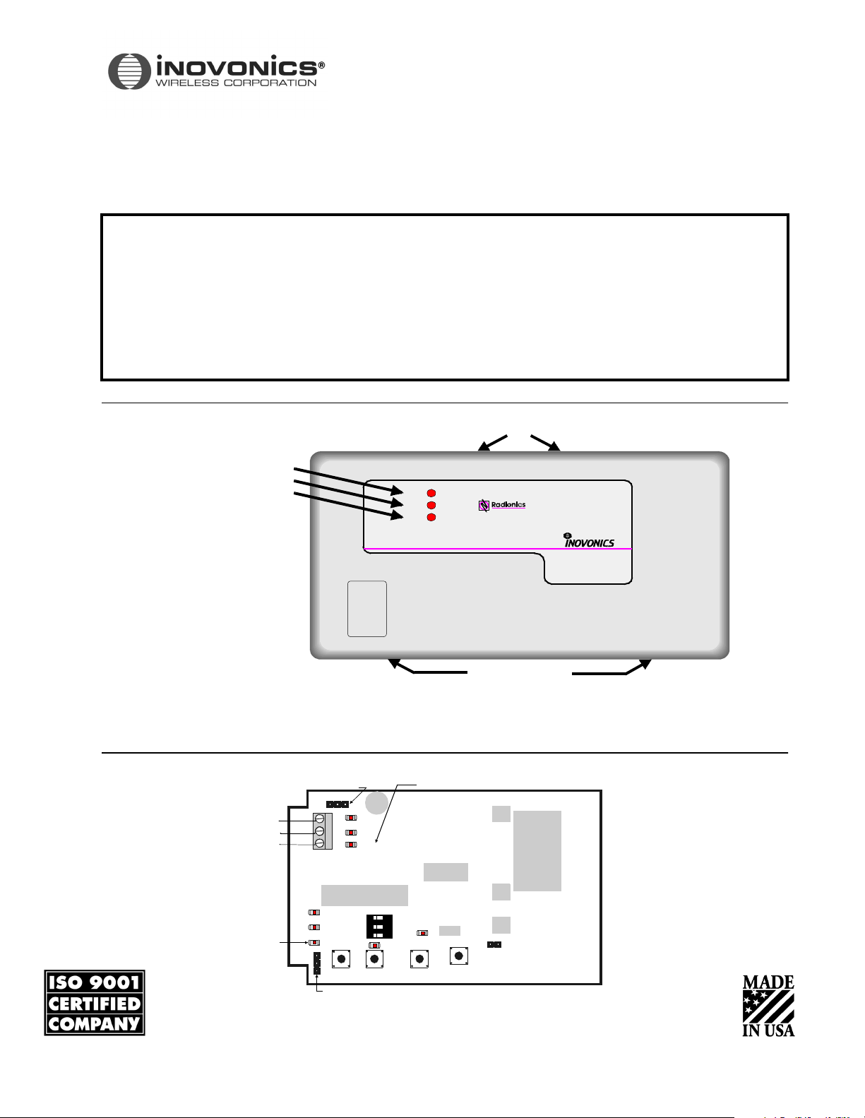
Housing Pry Slots
Housing Pry Slots
de LE D
DECODE
VALID
REPLY
900 MHz 16 POINT EXPANDER
For
2000 SERIES CONTROL PANELS
By
FA422 RECEIVE
Frequency Agile
®
Product Description
The FA422 is a 900MHz receiver that functions as a wireless point expander. This Expander
can process information from as many as 16 Inovonics transmitters and communicate their
individual point status to a specific class of Radionics control panels. The FA422 can
interface to all 2000 Series Control Panels that have wireless point expansion capability by
way of Radionics’ proprietary MonoBus. All Inovonics FA Series Security Transmitters and
Repeaters are compatible with the FA422. This product has been designed for quick and
easy indoor installation.
FIGURE 1
FIGURE 2
FA422 Housing
FA422 Programming and Diagnostic Components
Mono-Bus Address Jumper Reply LED
ADDRESS
78
To
Control Panel
DATA
AUX+
AUX—
DECODE
VALID
REPLY
Securi ty LED
ALT ARMING
COMMAND
SECURITY
TRANSMITTER
TYPE
Programming header
N/C
STD
STD
123
CUSTOM
OPTIONS
N/0
NO
W
EOL
SELECTED
SELECTED
EXT'D SPVN
WINDOW
TAMPER
LIT-FA422-Install © 1999 InovonicsWireless Corporation
02793.FM

Compatibility
Control Panels: All Radionics 2000 Series Control Panels with wireless point expansion capability
(includes D2212, D2212B, and D2412U)
Security Transmitters: Most FA Series Security transmitters.
Table 1: Security Transmitters Compatible with the FA422
Transmitter
Model Number
FA200 Universal (Door/Window) FA206I/S Inovonics and Sentrol PIRs
FA200W Universal Wide-Gap FA206DS Detection Systems PIR
FA210 Reduced-size Universal FA207 Glassbreak Detector
FA210W Reduced-size Universal Wide-Gap FA209 Billtrap
FA210M Reduced-size Universal for Momentary Switch FA216L/H Low and High Temperature Detectors
FA210DBN Reduced-size Universal with Switch De-bounce FA525 Repeater
FA250 High-Power Univer sal FA536 Locator
FA201
FA202
FA203S/D
FA205S/D
FA204
FA223S
Smoke detectors FA570 High-Power Indoor Repeater
Pendants FA575 High-Power Outdoor Repeater
Transmitter
Description
Tr an sm i tt er
Model Number
Tra nsm itt er
Description
Security transmitters can also be made to arm and disarm a system.
(See Alt Arming information, page8.)
Security Repeaters: All FA Series Security repeaters
Command Transmitters FA113 Three-function Command transmitter
(system arming/disarming FA100 Four-function Command transmitter
and special functions) (Note: The FA130 Wireless Keypad is NOT compatible with Radionics 2000 Series
Control Panels.)
CAUTION: If an FA100 is used with the Expander, the C key on the Radionics keypad(s) must not be
programmed for an emergency function.
Pressing the * key on the FA100 one time has the same effect on a 2000 series panel system as pressing
the C key on a Radionics keypad two times.
If the C key is programmed to perform an emergency function (like calling the police), accidentally
pressing the * key on the FA100 one time could activate the emergency function.
If it is desired to program the C key for an emergency function and have a Command transmitter
activate this function, use the FA113. The two * keys on the FA113 must be pressed simultaneously to
have the same effect as pressing the C key two times.
Specifications
Housing dimensions: 6.38" x 3.60" x 1.10"
Wei g ht : 5. 3 oz .
Power requirement: 10.2VDC-13.9VDC (provided by external power supply or by panel via MonoBus)
Current draw: 45mA typical, 60mA maximum
Receiver type: frequency-hopping spread-spectru
Operating Environment: 32°-122°F (0-50°C), up to 95% relative humidity (non-condensing)
FA422 Installation Manual Page 2 of 11
02793.FM

Expander, Control Panel, and Keypad Setup
Before installing the Expander and wireless point transmitters, it is recommended that the Expander, control panel, and a hardwired keypad be temporarily wired together. Panel programming should then be performed and each transmitter assigned a
point code. (It is easier to complete the necessary programming if all the equipment is in the same location.) The procedure is
as follows:
1. Make sure power has been removed from the control panel.
2. Using a short piece of multi-conductor cable, temporarily connect a hard-wired keypad to the control panel. (Refer to
Radionics keypad and control panel installation instructions.)
3. Remove the Expander’s cover. Use a small flat-bladed screwdriver to
indicated. (See Figu re1.)
4. Using another short piece of multi-conductor cable, temporarily connect the Expander to the control panel by connecting
DATA, AUX+ and AUX- terminals. (See Figu re3.)
pry housing cover open at pry point slots
gently
FIGURE 3
Expander, Control Panel and Keypad Connections
Keypad
Control
Panel
Data
Aux +
Aux –
5. Set up the Expander to respond to MonoBus address 7 or 8 by moving its address jumper.
(See Figure 4.)
FIGURE 4
Address Selection Header
ADDRESS
7
ADDRESS
8
7
8
FA422 Expander
ADDRESS
78
DATA
AUX+
AUX—
DECODE
VALID
REPLY
Address = 7
Address = 8
6. Apply power to the control panel.
7. Follow the Radionics control panel operating instructions and installation instructions to set up communication between
the keypad, control panel, and Expander. Note that when setting the Supervision Interval in the RF Parameters Group of
the panel’s program entry guide, a "1" indicates a 4-hour interval, not a 24-hour interval. (A "0" selection, however, still
means a 12-hour interval.)
Make sure the Expander address set-up at the control panel matches the Expander address
jumper selection. If everything is working properly, the REPLY LED on the Expander should be flashing. (See Fi gure2.)
8. Follow the control panel operating instructions to assign point codes to each transmitter. Assign point codes to Command
transmitters using the same procedure described for RF keypads
FA422 Installation Manual Page 3 of 11
02793.FM
Transmitter Programming
The Expander can program three different types of Inovonics transmitters:
• SECURITY transmitters are devices like universal transmitters (door/window sensors), pendants, wireless smoke
detectors, and wireless PIRs that send alarm, restoral, and check-in signals.
• COMMAND transmitters are devices that arm and disarm a system and send programmable command signals (such
as “Call the police,” or “Open the garage door”) to the control panel.
• ALT ARMING (Alternative Arming) transmitters are Security transmitters that are given the capability to arm and
disarm a system (like a Command transmitter). When a Security transmitter is programmed as ALT ARMING, its
alarm signal is interpreted by the Expander and sent to the panel as a system arming signal, and its restoral signal is
interpreted and sent as a system disarming signal. Unlike Command transmitters, Alt Arming transmitters can be
assigned point codes that monitor their check-in signals, tamper condition, and battery condition.
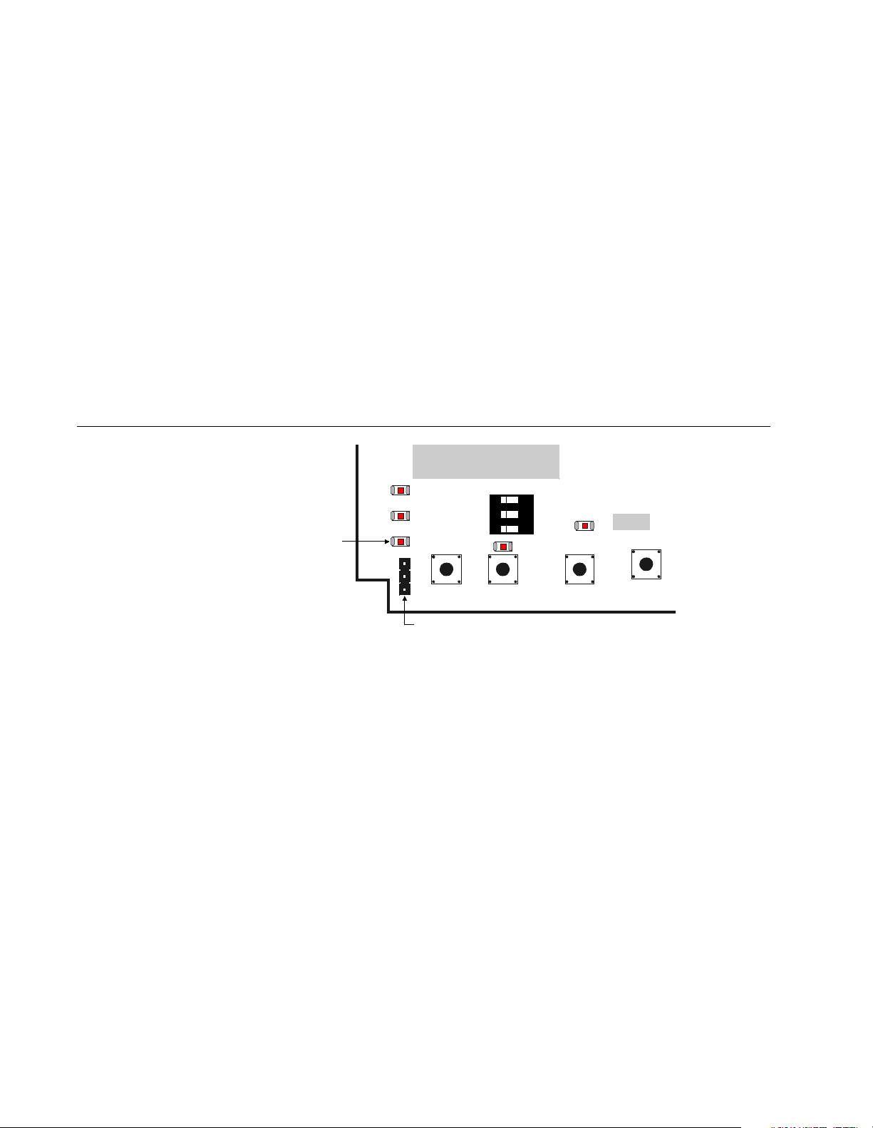
To set up the Expander for programming transmitters, locate the programming cable supplied with the Expander and plug one
end into the Expander’s programming header. (See F igure5.) When all transmitters have been programmed, remove the cable
from the Expander programming header, store the cable in the open area to the left of the Expander’s printed circuit board, and
put the Expander’s cover back on.
FIGURE 5
Expander Programming Detail
Security LED
ALT ARMING
COMMAND
SECUR ITY
TRANSMITTER
TYPE
N/C
STD
STD
OPTIONS
123
CUSTOM
N/0
NO
W
EOL
SELECT ED
SELECTED
EXT'D SPVN
WINDOW
Programming header
TAMPER
FA422 Installation Manual Page 4 of 11
02793.FM
 Loading...