

FA416 / FA416D
FA416R / FA416DR
Frequency Agile® 900MHz
16-Channel / 4-Output Receiver
Installation Instructions
02304E
Document revision history
Rev. Level Description Date
C Create F:\Eng\parts\02304\02304C.doc from
P:\Master.dox\FA_dox\FA416_v3.doc
7/19/01
D Replace ISO logo 10/08/01
E Page 5: replace “95%” with “90%”
Page 6: add “effectively reverses relay polarity”
Page 10: replace “access code to 3446” with “System ID”
10/29./02
Important Notes
This product is designed to be installed and maintained by professional
security technicians.
Unless specifically noted, Inovonics products are intended for indoor use. This
receiver is intended for use with indoor security systems. Use in outdoor
applications may impair performance.
Test system regularly.
Overview:
• The FA416 receiver is a high performance wireless receiver with 4 configurable alarm outputs and 1 global
fault output.
• The FA416 has default settings which permit 4 transmitters to be programmed to it. Two of these transmitters
may be normally open devices; two may be normally closed devices or have normally closed contacts.
• The FA416R and FA416DR have 5 onboard Form C relays. In all other respects they are identical to the
FA416 and FA416D.
• When the FA516 display module is added to the FA416 or FA416R, the assembly is designated the FA416D
and the FA464DR, respectively. The FA416D(R) can program and supervise 16 transmitters, with assorted
default assignments of external contact types and outputs. The display module indicates point numbers and
status of transmitter alarm and faults.
• The FA116 programmer can be used with either the FA416, FA416D, FA416R or FA416DR. The programmer
lets the user change all default settings for transmitters and outputs. With the FA116, users can program 16
points into the FA416 without the FA516 display module. The FA116 also has a signal level and signal margin
monitoring function, making it very useful for site surveys and troubleshooting.
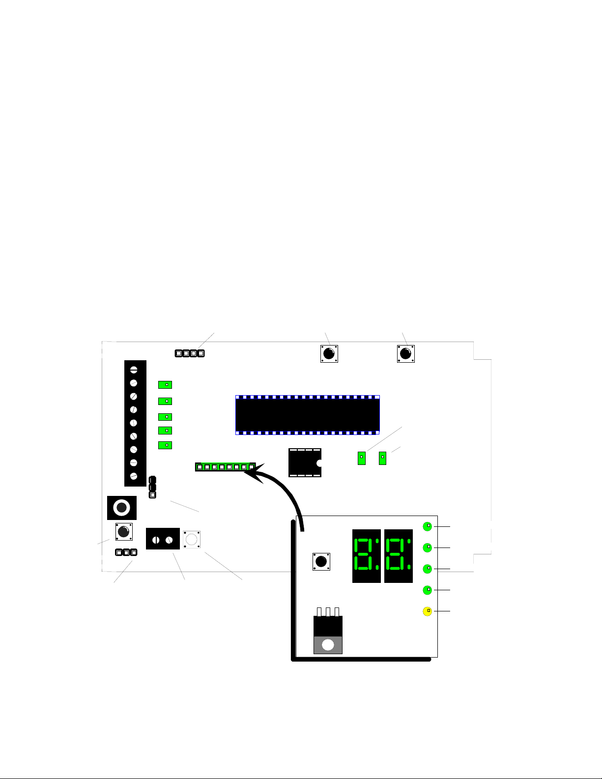
FA104 Programmer Port
FA416
16-Channel Receiver
Advance
Button
Delete
Button
DEL
Valid decode LED
Decode LED
DECODE
FA116
Programmer
Port
Reset
Button
Programming Port
13.6V
GND
RESET
1
2
3
4
FAULT
GND
RESET
Transmitter
Output 1 LED
Output 2 LED
Output 3 LED
Output 4 LED
Global Fault
LED
NC
NO
TMPR
Tamper Terminal
FA516 Display
Modul e co nnector
Output Select Jumper
block
Tamper switch
ADV
Review S ta tus
Button
VALID
DECODE
Transmitter # Display
FA516
Display Module
(Optional)
Figure 1: FA416 / FA416D receiver
Note: References in this manual to features shown In Figure 1 will be printed in italics.
Activated LED
Tamper LE D
Low battery LED
Inactive LED
Programmed LED
© 1997 Inovonics Wireless Corporation LIT-FA416-INSTALL 2 02304e 23-Oct-02
g
13.6V
g
13.6V
GND
GND
RESET
RESET
N/C
N/C
1 COM
1 COM
N/O
N/O
N/C
N/C
2 COM
2 COM
N/O
N/O
N/C
N/C
3 COM
3 COM
N/O
N/O
N/C
N/C
4 COM
4 COM
N/O
N/O
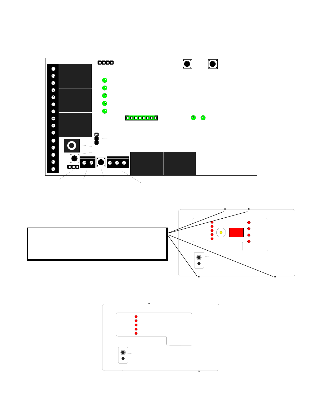
Figure 2: FA416R / FA416DR receiver
RESET
TX PRGM
FA104 Programmer Port
Output 1 LED
Output 2 LED
Output 3 LED
Output 4 LED
Global Fault LED
FA516 Display Module
NONC
FA116 Programmer Port
Reset Button
TMPR
Output Select Jumper
N/C
COM
N/O
Connector
Advance
Button
ADV DEL
VALID
DECODE
Delete
Button
DECODE
Case Tamper
Transmitter
Transmitter
Pro
ramming Port
ramming Port
Pro
Tamper
Tamper
Terminal
Terminal
Case Tamper
Switch
Switch
Fault Ouput Terminal
Note: References in this manual to features shown in Figure 2 will be printed in italics.
To open housing, insert small flat screwdriver at top or
bottom pry point indicator nubs (4 places). Gently twist or
OUTPUT 1
OUTPUT 2
OUTPUT 3
OUTPUT 4
FAULT
REVIEW
STATUS
pry housing cover away from base. Prying at any other
location will damage the housing.
Shown with access door removed.
To remove, insert small screwdriver
and gently pry door off.
Figure 3: FA416D / FA416DR receiver housing
OUTPUT 1
OUTPUT 2
OUTPUT 3
OUTPUT 4
FAULT
FA416
16 Channel Receiver
by Inovonics Corporation
TRANSMITTER
NUMBER
ACTIVATED
TAMPERED
LOW BATTERY
INACTIVE
FA416D
16 Channel Receiver
by Inovonics Corporation
Shown with access door removed.
To remove, insert small screwdriver
and gently pry door off.
Figure 4: FA416 / FA416R receiver housing
© 1997 Inovonics Wireless Corporation LIT-FA416-INSTALL 3 02304e 23-Oct-02

Features of the FA416 include:
• Fully supervises up to 16 FA transmitters.
• Outputs can be configured Normally Open or Normally Closed via Output select jumper. (One
configuration for all outputs.)
• For N/O configuration, output is open relative to ground. On activation, output pulls to common ground.
• For N/C configuration, output is held at common ground. On activation, output releases to open circuit.
• Technicians can observe output function by monitoring voltages between channel outputs and power on
the FA416 or resistance on the FA416R relay outputs.
• Transmitter, receiver and output options are factory assigned. They may be changed with the FA116
Executive Programmer or with the FA104 (upgraded C104) programmer.
• Intelligent global fault output for tamper, low battery and inactive transmitters. For example, if one of the
alarm outputs is assigned to monitor low battery faults, the fault output automatically becomes tamper and
inactive only.
• Manual and/or electronic reset of the receiver.
• Factory default programming: "Alarm" and "Inactive" outputs are programmed to follow transmitter status;
"Tamper" and "Low battery" outputs are latching. Latched outputs require the receiver to be reset.
• Simple restoral to factory defaults.
• Automatic exit from programming after 4 minutes of inactivity.
• Optional FA516 display module available.
• Cabling knockout in housing base.
• Cabling port with separate shutter.
• Case tamper switch and terminal block for connection to panel zone.
Additional features of the FA416D include:
• Status LEDs on the display module show transmitter activation, tamper, low battery and inactive.
• The Programmed LED blinks when the point IS NOT programmed, is on steady when the point IS
programmed.
Additional features of the FA416R and FA416DR include:
• Form C relays for alarm and fault outputs.
© 1997 Inovonics Wireless Corporation LIT-FA416-INSTALL 4 02304e 23-Oct-02

Technical Specifications:
Dimensions (housing): 6.38" x 3.60" x 1.10"
Weight: 6.9 oz.
9 oz FA416R and FA416DR
Environmental:
Operating temperature: 32°-140°F (0°-60°C)
Relative Humidity: 90% (non-condensing)
Electrical:
Power Requirement: 11 - 14 VDC, 450 mA
Power Consumption: 60 - 85 mA (without display)
75 - 225 mA (with display)
450 mA (with display and 5 relays active)
Typical: 60 mA (without display)
75 mA (with display)
115 mA (with display and 1 relay active)
Relay specifications: 1A @ 28VDC
0.5A @ 30VAC (resistive load)
Receiver:
Type: frequency-hopping spread spectrum
Operating frequency: 902-928 MHz
Installation:
Power: Supply power and ground to terminals marked 13.6V and GND on the terminal block.
Mounting: Use supplied hardware to attach FA416 housing to wall or surface. Where possible, orient the
antenna side of the receiver toward the majority of transmitters on the site. This enhances reception.
Opening the housing: Insert a small flat screwdriver behind pry point indicator nubs on top or bottom of the
housing cover. Gently twist or pry the housing cover away from the base.
Installing the FA516 display: Always disconnect power from the FA416 receiver before installing or removing
the FA516 Display Module. Visually check the mating of pins and header to make sure that all pins are seated
in the header.
Note: If the FA516 display is purchased separately from the FA416, it will be packaged with a housing cover
and graphic panel to replace the original FA416 cover. (Specify housing type.)
Installing the case tamper: Connect leads from the Case Tamper terminal block to a zone on the hardwire
panel. The switch is N/C with the cover on.
Attention: The FA540 relay module is not compatible with the new FA416 and FA416D receivers. If
relay outputs are required, the receiver unit must be either the FA416R or the FA416DR . The FA541 singlerelay module can still be used to provide relay operation off of individual outputs.
© 1997 Inovonics Wireless Corporation LIT-FA416-INSTALL 5 02304e 23-Oct-02
 Loading...