

FA404
4 Transmitter / Single Output Receiver
FA404R
4 Transmitter / Single Relay Output Receiver
Installation Instructions
02327C
Document revision history
Rev. Level Description Date
B Create F:\Eng\parts\02327\02327B.doc from
P:\Master.dox\FA_dox\FA404_v2.doc
C Replace ISO logo 8/08/01
7/19/01
!"The FA404 is designed to be installed and maintained by professional
security technicians.
!"Unless specifically noted, Inovonics products are intended for indoor use.
This receiver is intended for use with indoor security systems. Use in
outdoor applications may impair performance.
!"Test system regularly.
© 1998 Inovonics Wireless Corporation LIT -FA404-INSTALL
Important Notes
1
02327C.DOC 8-Oct-01
prog
Overview:
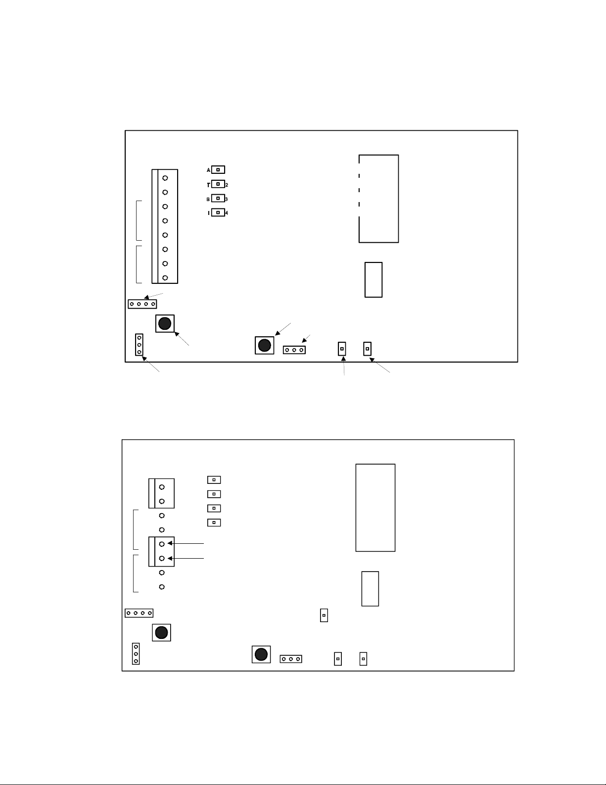
FA404 and FA404R slave receivers fully supervise up to four wireless transmitters. The FA404 has open
collector Alarm and Fault outputs. The FA404R has Form-C Alarm and Fault relay outputs.
13.6V
GND
COM
FAULT
COM
ALARM
NC
NO
NO
NC
FA404R receiver
1
Activated LED / Program poi nt 1
Tampered LED / Program point 2
Low battery LED / Program point 3
Inactive point LED / Progr am poi nt 4
Output configuration selector
1234
Transmitter programming button
TX PGM
RESET/DEL
Reset / Delete button
Transmitter
Tx PGM
ramming header
Transmitter exter nal c ontact selector
NCNO
VALID
DECODE
DECODE
Valid decode LED Decode LED
FA404 receiver
A
13.6V
GND
NC
COM
FAULT
NO
NO
COM
NC
ALARM
234
1
TX PGM
RESET/DEL
1
T2
B3
I4
Fault output
Alar m output
Tx PGM
VALID
DECODE
NCNO
DECODE
© 1998 Inovonics Wireless Corporation LIT -FA404-INSTALL
2
02327C.DOC 8-Oct-01
Technical Specifications:
Dimensions (housing): 6.38" x 3.60" x 1.10"
Weight: 6.9 oz.
Environmental:
Operating temperature: 32°-120°F (0°-50°C)
Relative Humidity: 95% (non-condensing)
Electrical:
Power Requirement: 11-14 VDC
Power Consumption: 130mA (max, relays activated)
Typical: 40mA (quiescent)
FA404R output relay Form C, 1A @ 28VDC, 0.5A @ 30VAC (resistive)
Receiver:
Type: frequency-hopping spread spectrum
Operating frequency: 902-928 MHz
VALID DECODE LED
The
The receiver programs transmitters with the following fixed parameters:
• No EOL resistor.
• No Internal Contact. (The FA404 and FA404R will
internal magnet contact.)
• 60-second supervisory check-in. (The transmitter sends a supervisory signal every 60 seconds. Some
transmitters check in at 150-second intervals.) The receiver, with a fixed 4-hour supervisory window,
will declare a programmed point inactive if no transmission is received during every 4 hour window.
• The Fault Output is Latching for low battery or tamper faults. It is Follower for Inactive faults.
• The Alarm Output is user-selectable to be follower, momentary, latching or toggle.
FA transmitters have non-volatile memory.
Note:
power or changing batteries. Press the transmitter reset button to restore programming.
indicates transmissions from transmitters programmed to the receiver.
not
support the FA200W or FA210W widegap
It is not necessary to reprogram transmitters after losing
Installation:
Power
Mounting:
out the back of the unit, use a small side cutter or utility knife to remove the knockout in the housing base.
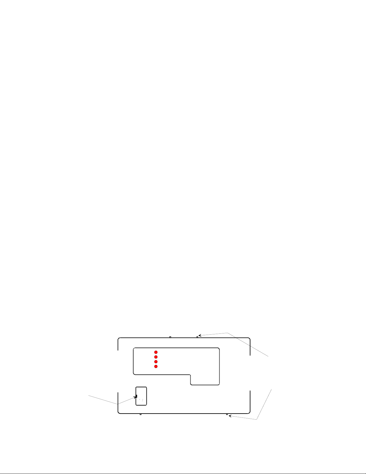
Opening the housing:
Reset Button Access Cover:
Insert small screwdriver
in slot on left side. Hold cover
lightly while pryi ng. Install by
inserting top latch and
snapping in at bottom.
: Supply power and ground to terminals marked
13.6V
and
on the terminal block.
GND
Use supplied hardware to attach FA404 or FA404R housing to wall or surface. To route wiring
ACTIVATED
TAMPERED
LOW BATTERY
INACTIVE
Frequen c y A gile
Receiver
by Inovonics Corpor a tion
Insert a small flat screwdriver
behind pry point indicator nubs
on top or bottom of the housing
cover (4 places). Gently pry or
twist the housing cover apart.
© 1998 Inovonics Wireless Corporation LIT -FA404-INSTALL
3
02327C.DOC 8-Oct-01

Programming Alarm Output Configuration:
1) Select alarm output trip options according to the following table. Set jumpers on the
SELECTOR
as indicated.
Pins 1-2 Pins 3-4 Output Trip Mode
Off Off Follow
On Off Momentary
(Output will remain on for 4 to 10 seconds from last alarm transmission.
Output will stay on during continuous alarm transmissions.)
Off On Latch
On On Toggle
(After releasing the button allow at least 5 seconds between transmissions
to toggle devices on and off.)
WARNING: Do not use the FA404 toggle mode in applications requiring precision control or timing.
OUTPUT CONFIGURATION
Programming transmitters:
1) Select Normally Open (NO) or Normally Closed (NC) transmitter contact by positioning the jumper on the
receiver's 3-pin transmitter external contact selector.
2) Plug programming cable to 3-pin
connnector to the header pins makes no difference.
3) Press the
transmitter. The receiver goes into program mode. Continue pressing until the desired transmitter is selected (1-
4). A flashing LED indicates that a point has not been previously programmed. Program mode ends as soon as
the transmitter is programmed or times out after 30 seconds.
TRANSMITTER PROGRAMMING BUTTON
TRANSMITTER PROGRAMMING HEADER
on the receiver.
Hold for at least 1 second
on the receiver. Orientation of the cable
to select the
4) Connect the programming cable to 3-pin header on transmitter. Orientation of the connector to header pins does
not matter.
Press the transmitter
5)
reset buttons.)
6) If programming is successful, the program point LED will change from flashing to steady when the reset button is
released.
reset button for at least 2 seconds.
Note: Any combination of N/O or N/C transmitters can be programmed.
(Refer to pages 6 and 7 for locations of transmitter
Replacing one transmitter with another:
1) Before programming a new transmitter to a previously used point, delete the first transmitter as shown below.
2) Pull the battery from the first transmitter to prevent it from continuing to transmit with the same point identification.
WARNING: Inovonics strongly advises against using more than one transmitter per point.
3)
supervision is lost and the possibility exists that alarm transmissions might be missed or cancelled by concurrent
restoral or supervisory signals from identically programmed transmitters.
Discrete
Deleting a transmitter:
1) Press the
TRANSMITTER PROGRAMMING BUTTON
on the receiver to select the transmitter point number.
2) Press the
the point. The LED will change from steady to flashing when the point is deleted.
NOTE: Transmitters which have been programmed to the receiver but which are subsequently removed or not
used must be deleted from the system to prevent occurrence of Inactive fault in 4 hours.
© 1998 Inovonics Wireless Corporation LIT -FA404-INSTALL
RESET / DELETE B U TTON
. This instructs the receiver that there is no longer a transmitter programmed to
4
02327C.DOC 8-Oct-01

Receiver Operation:
Output activation:
On activation, output pulls to common ground. The FA404R has Form C Alarm and Fault relay outputs. Output
The FA404 has N/O open collector Alarm and Fault outputs. Output is open relative to ground.
activation is indicated by illumination of the
closed zone, the FA404R must
Connection to hardwire panels:
be used.
When an FA404 or FA404R receiver is used with a hardwire security panel, the
ACTIVATED LED
.
Note: if a receiver is being connected to a normally
panel will typically supply power and ground to the receiver. When the ground supplied to the receiver is common
to the return loops of the hardwire panel, use one wire to connect each of the FA404 receiver outputs to the zone
input of the panel. Supervision resistors in N/O loops must be placed in parallel. Supervision resistance in N/C
loops must be in series. The examples below show typical connections of both the FA404 and the FA404R.
FA404R, N/C configuration
13.6VDC
GROUND
EOL resistors, if required
for N/C configuration
13.6V
13.6V
GND
GND
N/C
N/C
FAULT ALARM
COM
N/O
N/O
N/O
COM
N/C
NOTE: GROUND AND
RETURNS ARE NOT
COMMON.
PANEL
FAULT SUPERVISIO N ZONE
FAULT ZONE RETURN
ALARM ZONE RETURN
13.6VDC
GROUND
ALARM ZONE
FA404R, N/O configuration
13.6V
13.6V
GND
GND
N/C
N/C
FAULT
COM
N/O
N/O
ALARM
N/O
COM
N/C
EOL resistors, if required
for N/O configuration
NOTE: GROUND AND
RETURNS ARE
RETURN
PANEL
COMMON.
NOTE: GROUND AND
RETURNS ARE NOT
COMMON.
13.6VDC
GROUND
FAULT SUPERVISIO N ZONE
ALARM ZONE
PANEL
FAULT ZONE RETURN
FAULT ZONE
ALARM ZONE
ALARM ZONE RETURN
FA404
13.6V
13.6V
GND
GND
N/C
N/C
FAULT ALA RM
COM
N/O
N/O
N/O
COM
N/C
EOL resistors, if required
WARNING:
To clear a latched fault or alarm, press
or the transmitter will be deleted.
Test all transmitters prior to leaving the site.
RESET
Make sure that the receiver is not in program mode
.
If the panel has N/O zones and can recognize 3 zone conditions (open=fault, short=alarm and EOL
resistance=normal), both the alarm and the fault outputs can be attached to the same zone as shown below.
NOTE: GROUND AND
RETURNS ARE NOT
COMMON.
ZONE INPUT
COMMON
PANEL
13.6VDC
GROUND
FA404R, 3-WAY CONFIGURAT ION
13.6V
13.6V
GND
GND
N/C
N/C
FAULT
COM
N/O
N/O
ALARM
N/O
COM
N/C
Resistor provided with
hardwire panel
© 1998 Inovonics Wireless Corporation LIT -FA404-INSTALL
5
02327C.DOC 8-Oct-01

s
Frequency Agile
FA200
Universal Transmitter
Reset button
Programming
header
Bat
t
e
Tamper switch
r
y
Universal Widegap Transmitter
Widegap Magnet
Widegap
reed switch
Series Transmitters
FA200W
Reset button
Programming
header
not supported
by the FA404
Battery
Tamper switch
FA202
Smoke Detector
Reset Button
Programming
Header
Battery terminals
Program c ontacts: N/O or N/C, as needed
Typical battery life: 3 years
Battery type: 4.5V alkaline battery pack
Switch trigger: 1.5 seconds, minimum
Dimensions: 1.25" x 6.00" x 0.750"
FA203
Pendant Transmitter
Reset button
Programming header
3.0V
+
Program contacts: N/O
Typical battery life: 3-5 years
Battery (or equivalent): 3.0V lithium Sanyo CR2
Dimensions: 3.10" x 1.62" x 0.750"
* To extend battery life, actual chec k-in
interval of the FA203 is 2 to 3 ti mes the
programmed value.
Battery terminals
Program c ontacts: N/O or N/C, as needed
Internal contact: not supported by FA404
Typical battery life: 3 years
Battery type: 4.5V alkaline battery pack
Switch trigger: 1.5 seconds, minimum
Dimensions: 1.25" x 6.00" x 0.750"
FA204
Pendant Transmitter
+
3.0V
Reset button
Note: Remove battery cover to acces
Reset Button and Programming Head
Programming
header
Program contacts: N/O
Typical battery life: 2 years
Battery 3.0V Sanyo LiMn CR14250
Dimensions: 2.8" x 1.7" x 0.83"
Program contacts: N/C
Typical battery life: 1 year
2 Batteries: 3V lithium
Dimensions: 6.0" Diameter
Note: Remove jumper to program,
replace jumper af ter programming.
FA205
Beltclip Transmitter
Reset button
Programming header
3.0V
+
Program contacts: N/O
Typical battery life: 3-5 years
Battery (or equivalent): 3.0V lithium Sanyo CR2
Dimensions: 3.10" x 1.62" x 0.750"
* To extend battery life, actual chec k-in
interval of the FA205 is 2 to 3 ti mes the
programmed value.
FA206S
PIR Motion Detector
Reset button
1-zone or 2-zone
detection header
Programming header
3.0V
+
Tamper switch
Battery
Program contacts: N/C
Typical battery life: 2 years
Battery: 3.0V lithium Duracell DL123A
Sleep after trip: 90-103 seconds
Dimensions: 3.75" x 2.88" x 2.40"
Note: Batteries are always s upervi sed. Lithium batteri es are capacity-tested at 18-hour intervals. Typical bat tery life is based on 60-sec ond
© 1998 Inovonics Wireless Corporation LIT -FA404-INSTALL
check-in. The transmitter will deactivate 2 weeks after low battery is detected.
FA206DS
PIR Motion Detector
Programming
header
Sensitivity selector
Walk test LED
Mirror Optics
3.0V
+
Reset button
Tamper switch
Program contacts: N/O
Typical battery life: 2 years
Battery: 3.0V lithium DL123A
Program contacts: N/C
Typical battery life: 2 years
Battery: 3.0V lithium DL123A
Sleep after trip: 180 seconds
Dimensions: 3.75" x 5.75" x 2.50"
Dimensions: 4.25" x 3.12" x 1.63"
Note: Remove jumper to program,
replace jumper af ter programming.
Test weekly.
6
FA207
Glassbreak Detector
Programming header
Reset button
(with tamper shunt)
+
02327C.DOC 8-Oct-01
3.0V

Frequency Agile
FA209
Billtrap Transmitter
3V LITHIUM
Delay selector
3V LITHIUM
Reset button
Tamper switch
Programming header
Program contacts: N/O
Typical battery life: 1-2 years
Battery type (Qty. 2): 3.0V lithium CR2450N
Dimensions: 2.63" x 6.19" x 0.750"
Series Transmitters (Continued)
FA210
Reduced-size
Universal Transmitter
Programming header
Reset button
3.0V+
Tamper switch
Program c ontacts: N/O or N/C, as needed
Typical battery life: 4 years
Battery type: 3.0V lithium DL123A
Switch trigger: 1.5 seconds, minimum
Dimensions: 3.55" x 1.70" x 0.920"
FA210W
Reduced-size
Universal Widegap Transmitter
Widegap Magnet
not supported
by the FA404
Program c ontacts: N/O or N/C, as needed
Internal contact: not supported by FA404
Typical battery life: 4 years
Battery type: 3.0V lithium DL123A
Switch trigger: 1.5 seconds, minimum
Dimensions: 3.55" x 1.70" x 0.920"
FA210W Widegap
Reed switches
3.0V+
Reed switch
indicator
FA250
High PowerTransmitter
+
Tamper Switch
Reset Button
Programming Header
Program c ontacts: N/O or N/C, as needed
Typical battery life: 1-2 years
Battery type: 3.0V lithium DL123A
Switch trigger: 1.5 seconds, minimum
Dimensions: 1.25" x 6.00" x 0.750"
3.0V
External contact
Terminals
© 1998 Inovonics Wireless Corporation LIT -FA404-INSTALL
Note: Batteries are always s upervi sed. Lithium batteri es are capacity-tested at 18-hour intervals. Typical bat tery life is based on 60-sec ond
check-in. The transmitter will deactivate 2 weeks after low battery is detected.
7
Test weekly.
02327C.DOC 8-Oct-01

Warranty & Disclaimer
Inovonics Wireless Corporation ("Inovonics") warrants its products ("Product" or "Products") to conform to its own
specifications and to be free of defects in materials and workmanship under normal use for a period of twenty-four (24)
months from the date of manufacture. Within the warranty period Inovonics will repair or replace, at its option, all or any
part of the warrantied product. Inovonics will not be responsible for dismantling and/or reinstallation charges. To
exercise the warranty, the User ("User", "Installer" or "Consumer") must be given a Return Material Authorization
("RMA") Number by Inovonics. Details of shipment will be arranged at that time.
This warranty does not apply in cases of improper installation, misuse, failure to follow installation and operating
instructions, alteration, abuse, accident or tampering, and repair by anyone other than Inovonics.
This warranty is exclusive and expressly in lieu of all other warranties, obligations or liabilities, whether written, oral,
express, or implied, including any warranty of merchantability or fitness for a particular purpose. Inovonics will not be
liable to anyone for any consequential or incidental damages for breach of this warranty or any other warranties.
This warranty will not be modified, varied or extended. Inovonics does not authorize any person to act on its behalf to
modify, vary or extend this warranty. This warranty will apply to Inovonics Products only. All other products,
accessories or attachments used in conjunction with Inovonics equipment, including batteries, will be covered solely by
their own warranty, if any. Inovonics will not be liable for any direct, incidental or consequential damage or loss
whatsoever, caused by the malfunction of Product due to products, accessories, or attachments of other
manufacturers, including batteries, used in conjunction with Inovonics Products.
This warranty does not warrant the replacement of batteries that are used to power Inovonics Products.
The User recognizes that a properly installed and maintained security system may only reduce the risk of events such
as burglary, robbery, personal injury and fire. It does not insure or guarantee that there will be no death, personal
damage and/or damage to property as a result.
compromised and/or circumvented, or that the Product will prevent any death, personal and/or bodily injury
and/or damage to property resulting from burglary, robbery, fire or otherwise, or that the Product will in all
cases provide adequate warning or protection.
Inovonics shall have no liability for any death, injury or damage, however incurred, based on a claim that
Inovonics Products failed to function.
damage arising under this limited warranty or otherwise, regardless of cause or origin, Inovonics' maximum liability will
not in any case exceed the purchase price of the Product, which will be fixed as liquidated damages and not as a
penalty, and will be the complete and exclusive remedy against Inovonics.
Warning: The User should follow all installation, operation and maintenance instructions.
!
!
advised to conduct Product and systems tests at least once each week. Changes in environmental conditions, electric
or electronic disruptions and tampering, may cause the Product to not perform as expected.
Warning: Inovonics warrants its Product to the User.
taking necessary precautions for the safety and protection of lives and property wherever Inovonics Products are
installed. Inovonics strongly advises the User to program Products to be supervised whenever used in applications
affecting life safety. Users are warned that unsupervised devices are subject to undetected failure due to malfunction,
battery failure, tampering, or changes in environment.
Inovonics does not claim that the Product may not be
However, if Inovonics is held liable, directly or indirectly, for any loss or
The User is responsible for exercising all due prudence and
The User is strongly
© 1998 Inovonics Wireless Corporation LIT -FA404-INSTALL
8
02327C.DOC 8-Oct-01

Frequency Agile
from
Inovonics
Receivers
:
FA401
Single Transmitter / Single Output
FA401R
FA404R
FA416D
FA416R
FA416DR
FA464DR
Single Transmitter / Single Relay Output
FA404
4-Transmitter / Single Output
4-Transmitter / Single Relay Output
FA416
16-Transmitter / 4-output
16-Transmitter / 4-output with display
16-Transmitter / 4-relay output
16-Transmitter / 4-relay output with display
64-Transmitter / 16-relay output with display
Receiver Accessories:
FA116
Executive Programmer for FA416 / FA464
FA516
Display module for FA416 and FA416R
Inovonics Wireless Corporation
315 CTC Blvd
Louisville CO 80027
(800)782-2709
FAX: (303)939-8977
E-MAIL: support@inovonics.com
www.inovonics.com
© 1998 Inovonics Wireless Corporation LIT -FA404-INSTALL
9
02327C.DOC 8-Oct-01
 Loading...