

Page 1
FA207 Frequency Agile® ShatterPro™ Glassbreak
Transmitter
Installation and Operation Manual - 01877D
1 Overview
The FA207 is a an acoustic glassbreak sensor that transmits digital RF messages to
Inovonics Wireless FA receivers. The glassbreak sensor module is the wireless
Shatterpro®, manufactured by GE Interlogix, Inc. The wireless transmitter module is
manufactured by Inovonics Wireless Corporation
1.1 Inovonics Wireless Contact Information
If you have any problems with this procedure, contact Inovonics Wireless technical
services:
• E-mail: support@inovonics.com
• Phone: (800) 782-2709; (303) 939-9336
B
FA207 Frequency Agile® ShatterPro™ Glassbreak
Transm i tter
Installation and Operation Manual - 01877D
1 Overview
The FA207 is a an acoustic glassbreak sensor that transmits digital RF messages to
Inovonics Wireless FA receivers. The glassbreak sensor module is the wireless
Shatterpro®, manufactured by GE Interlogix, Inc. The wireless transmitter module is
manufactured by Inovonics Wireless Corporation
1.1 Inovonics Wireless Contact Information
If you have any problems with this procedure, contact Inovonics Wireless technical
services:
• E-mail: support@inovonics.com
• Phone: (800) 782-2709; (303) 939-9336
B
A
C
A
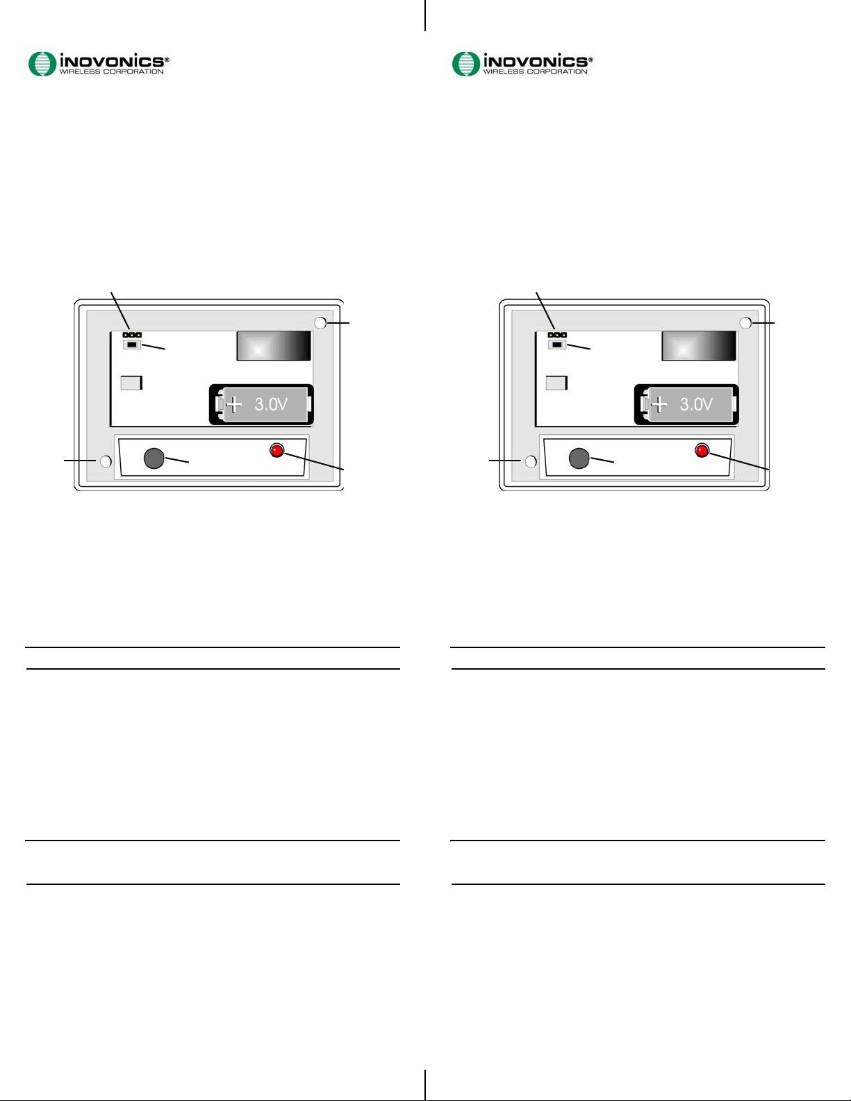
Figure 1 FA207 Components
A. Mounting holes B. Programming header C. Reset button
D. Microphone E. Sensor LED
D
E
2 Installation and Startup
2.1 Install the Battery
Before installing the FA207 glassbreak transmitter you will need to install the
battery. To install the battery:
1. Press the housing release tab on the bottom of the FA207 housing; pull the
housing apart.
2. Install the battery (Fig. 1).
3. Press the Reset button to initialize the transmitter (Fig. 1).
Note: You must press the Reset button each time the battery is changed.
2.2 Program the FA207
The FA207 must be programmed as follows to communicate with your FA system:
1. Remove the tamper jumper from the programming header.
2. Connect the programming device’s cable to the FA207 programming header.
3. Program the FA207 using the control panel or receiver manual. The FA207 must
be programmed as follows to communicate with your FA system:
• External contacts: Normally open
• End of line: No
• Internal contact: No
• Check-in time: 60 seconds (recommended)
4. Press the FA207 Reset button.
5. Disconnect the programming cable.
6. Replace the jumper on the center pin and either the inside or outside pin of the
programming header.
Note: The FA207 retains programming data in non-volatile memory. It does not
require re-programming after loss of power. Press Reset to re-initialize the FA207
and restore programming.
2.3 Mount the FA207
1. Use the provided anchors and screws to mount the FA207, paying careful
consideration to the following best practices:
• To avoid false alarms, install the unit as a perimeter zone that is armed only
when the perimeter doors and windows are armed. Installing the unit as a 24hour zone can create false alarms.
• Mount the FA207 at least .91 m (3ft) from the window to be monitored, but
no more than 7.62 m (25ft) away.
• Mount the FA207 at least 1.2 m (4 ft) away from noise sources (televisions,
speakers, sinks, doors, etc.).
• Mount the FA207 so that it is in direct line of sight of all windows to be
protected.
A
C
A
Figure 2 FA207 Components
A. Mounting holes B. Programming header C. Reset button
D. Microphone E. Sensor LED
D
E
2 Installation and Startup
2.1 Install the Battery
Before installing the FA207 glassbreak transmitter you will need to install the
battery. To install the battery:
1. Press the housing release tab on the bottom of the FA207 housing; pull the
housing apart.
2. Install the battery (Fig. 1).
3. Press the Reset button to initialize the transmitter (Fig. 1).
Note: You must press the Reset button each time the battery is changed.
2.2 Program the FA207
The FA207 must be programmed as follows to communicate with your FA system:
1. Remove the tamper jumper from the programming header.
2. Connect the programming device’s cable to the FA207 programming header.
3. Program the FA207 using the control panel or receiver manual. The FA207 must
be programmed as follows to communicate with your FA system:
• External contacts: Normally open
• End of line: No
• Internal contact: No
• Check-in time: 60 seconds (recommended)
4. Press the FA207 Reset button.
5. Disconnect the programming cable.
6. Replace the jumper on the center pin and either the inside or outside pin of the
programming header.
Note: The FA207 retains programming data in non-volatile memory. It does not
require re-programming after loss of power. Press Reset to re-initialize the FA207
and restore programming.
2.3 Mount the FA207
1. Use the provided anchors and screws to mount the FA207, paying careful
consideration to the following best practices:
• To avoid false alarms, install the unit as a perimeter zone that is armed only
when the perimeter doors and windows are armed. Installing the unit as a 24hour zone can create false alarms.
• Mount the FA207 at least .91 m (3ft) from the window to be monitored, but
no more than 7.62 m (25ft) away.
• Mount the FA207 at least 1.2 m (4 ft) away from noise sources (televisions,
speakers, sinks, doors, etc.).
• Mount the FA207 so that it is in direct line of sight of all windows to be
protected.
Page 2

• The best location for mounting the FA207 is on the wall opposite of the
window to be protected. The FA207 may also be mounted on the wall adjoining
the window to be protected, or on the ceiling.
• The glass should have the following minimum dimensions:
- Dimensions: 0.3 m x 0.6 m (1 x 2ft) or larger
- Plate thickness: 2.4 mm to 6.4 mm (3/32" to 1/4")
- Tempered thickness: 3.2 mm to 6.4 mm (1/8" to 1/4")
- Wired thickness: 6.4 mm (1/4")
- Laminated thickness: 3.2 mm to 6.4 mm (1/8" to 1/4")
• Avoid glass airlocks and glass vestibule areas, noisy kitchens and residential
car garages.
• Avoid rooms smaller than 3 x 3 m (10 x 10 ft), such as small utility rooms,
stairwells and small bathrooms.
• Because the unit is not hermetically sealed, avoid humid rooms.
• Avoid rooms where white noise, such as air compressor noise, is present. (A
blast of compressed air may cause a false alarm.)
• Avoid rooms with noise insulation or sound-deadening drapes or with closed,
wooden window shutters inside.
• Avoid placing the FA207 in the corner of a room.
2.4 Test the FA207
The FA207 should be tested following installation. Though full functionality testing
requires use of the Sentrol 5709C acoustic glassbreak tester, which switches the
unit into test mode and simulates alarm conditions via sonic bursts, the FA207 may
be field-tested by doing the following:
1. Remove the programming header jumper to test the transmitter. This should
cause a tamper fault (Fig. 1).
2. Clap your hands loudly in front of the sensor to test the microphone. The LED will
blink twice, but the alarm will not trip (Fig. 1).
3 Specifications
Dimensions: 4.2” x 3.1” x 1.7”
Operating environment: 0°- 60°C (32°- 140°F), 90% relative humidity, non-
condensing.
Battery: 3V lithium
Operating frequency 902-928 MHz
Microphone: Omnidirectional Electret
4 Warranty/Disclaimer
Caution: Changes or modifications to this unit not expressly approved by
Inovonics Wireless Corporation may void the installer's authority to operate the
equipment as well as the product warranty.
Inovonics Wireless Corporation ("Inovonics") warrants its products ("Product" or
"Products") to conform to its own specifications and to be free of defects in
materials and workmanship under normal use for a period of twenty-four (24)
months from the date of manufacture. Within the warranty period, Inovonics will
repair or replace, at its option, all or any part of the warranted Product. Inovonics
will not be responsible for dismantling and/or reinstallation charges. To exercise
the warranty, the User ("User", "Installer" or "Consumer") must work directly
through their authorized distributor who will be given a Return Material
Authorization ("RMA") number by Inovonics. Details of shipment will be arranged
directly through the authorized distributor.
This warranty is void in cases of improper installation, misuse, failure to follow
installation and operating instructions, alteration, accident or tampering, and
repair by anyone other than Inovonics.
This warranty is exclusive and expressly in lieu of all other warranties, obligations
or liabilities, whether written, oral, express, or implied. There is no warranty by
Inovonics that Inovonics product will be merchantable or fit for any particular
purpose, nor is there any other warranty, expressed or implied, except as such is
expressly set forth herein. In no event shall Inovonics be liable for an incidental,
consequential, indirect, special, or exemplary damages, including but not limited to
loss of profit, revenue, or contract, loss of use, cost of down time, or interruption of
business, nor any claim made by distributor's customers or any other person or
entity.
This warranty will not be modified or extended. Inovonics does not authorize any
person to act on its behalf to modify or extend this warranty.
This warranty will apply only to Inovonics Products. Inovonics will not be liable for
any direct, incidental, or consequential damage or loss whatsoever, caused by the
malfunction of Product due to products, accessories, or attachments of other
manufacturers, including batteries, used in conjunction with Inovonics Products.
Note: E-mail support@inovonics.com for a copy of the CE Declaration of
Conformity.
© 2005 Inovonics Wireless - www.inovonicswireless.com
© 2005 Inovonics Wireless - www.inovonicswireless.com
 Loading...