

FA206DS
Frequency Agile®
Passive InfraRed Motion Detector
900MHz Transmitter
Installation Instructions
02154B
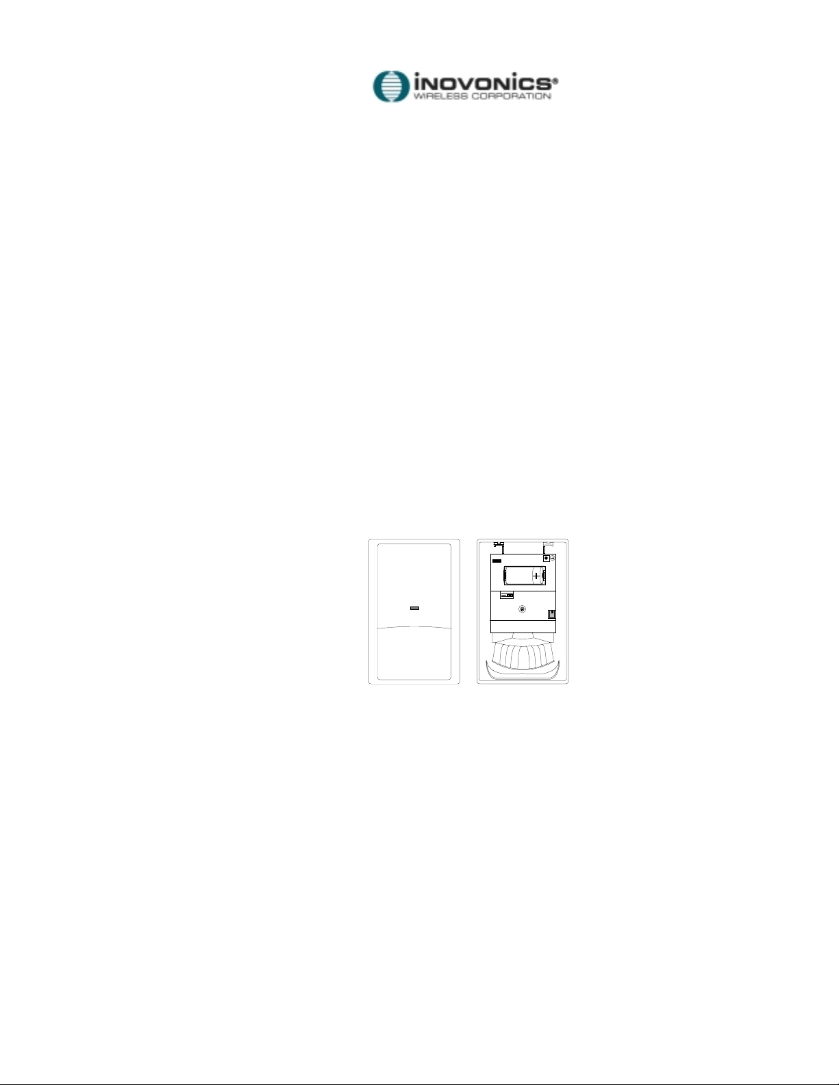
Overview:
The FA206DS is an Inovonics transmitter incorporating the Detection Systems DS-775RF PIR. The unit
operates on a single 3.0V lithium battery (Duracell DL123A or equivalent).
Features:
!"
Inovonics' reliable 900 Megahertz
!"
Motion Analyzer II™ signal processing.
!"
3 interchangeable coverage patterns available for special applications (optional).
!"
Internally pointable, field-replaceable mirrored optics.
!"
5 mounting options permit flat wall, corner or hallway mounting, with swivel adjustments for aiming for
nominal coverage.
!"
RFI Interference Immunity.
Frequency Agile
®
radio link.
3.0V
Specifications:
Dimensions: 3.75"W x 5.75"L x 2 .50"D
Operating temperature: 32#F to 120#F
Voltage: 3 VDC
Battery: 1 - 3.0V lithium (Duracell DL123A or equivalent)
Note: Battery is always supervised
Broad coverage area: 50' x 50'
Barrier coverage area: 80' x 16'
Long Range coverage area: 120' x 10'
Mirror adjustment: +2# to -18# vertical, +10# to -10# horizontal
Sensitivity adjustment: Standard, Intermediate and High; jumper selectable
Test LED: Externally visible LED (during walk test mode)
Important Notes
!"
These products are designed to be installed and maintained by professional security technicians.
!"
Products, unless specifically noted, are intended for indoor use.
!"
Manually test all products regularly.
© 1996 Inovonics W i rel ess Corporation
02154b.doc LIT-FA206DS-INSTALL hc:7-Aug-01
1
!"
Installation:
Mounting Note: Recommended mounting height range is 6'6" to 8'6". Recommended mounting
height is 7'6"(2.25m).
General mounting advice:
!"
For best detection, locate the FA206DS so that intruders move
across
detection coverage patterns,
rather than toward or away from the sensor.
!"
The mounting surface should be solid and vibration-free.
!"
Check areas for potential sources of false alarms. Remember that the sensor responds to quick
changes in heat patterns within its coverage pattern. Avoid locating it where it is exposed to direct or
reflected sunlight, or to objects which can be heated quickly by sunlight. Do not place the FA206DS
looking at windows. Don't place it near heat or cold sources, like heater ducts or air conditioners, which
might direct hot or cold air onto the sensor. Look for appliances such as space heaters which can
rapidly heat up.
!"
Find out about normal use of the area. Are there pets? Might there be birds, for example, in a
warehouse?
!"
When the sensor might detect users who enter the protected area through a delayed door, program the
sensor as a "Follower" device.
!"
Make end-users aware of the location of the FA206DS and caution them about obstructing the coverage
pattern when re-arranging furniture or stock.
Mounting Instructions:
The FA206DS may be mounted with or without the optional swivel or gimbal brackets. Without the brackets
the unit may be attached to walls or corners through the back of the detector housing.
Set screw
stop block
Corner Mount
Surface Mount
Bracket Mount
Corner Mount
Surface Mount
Corner Mount
Corner Mount
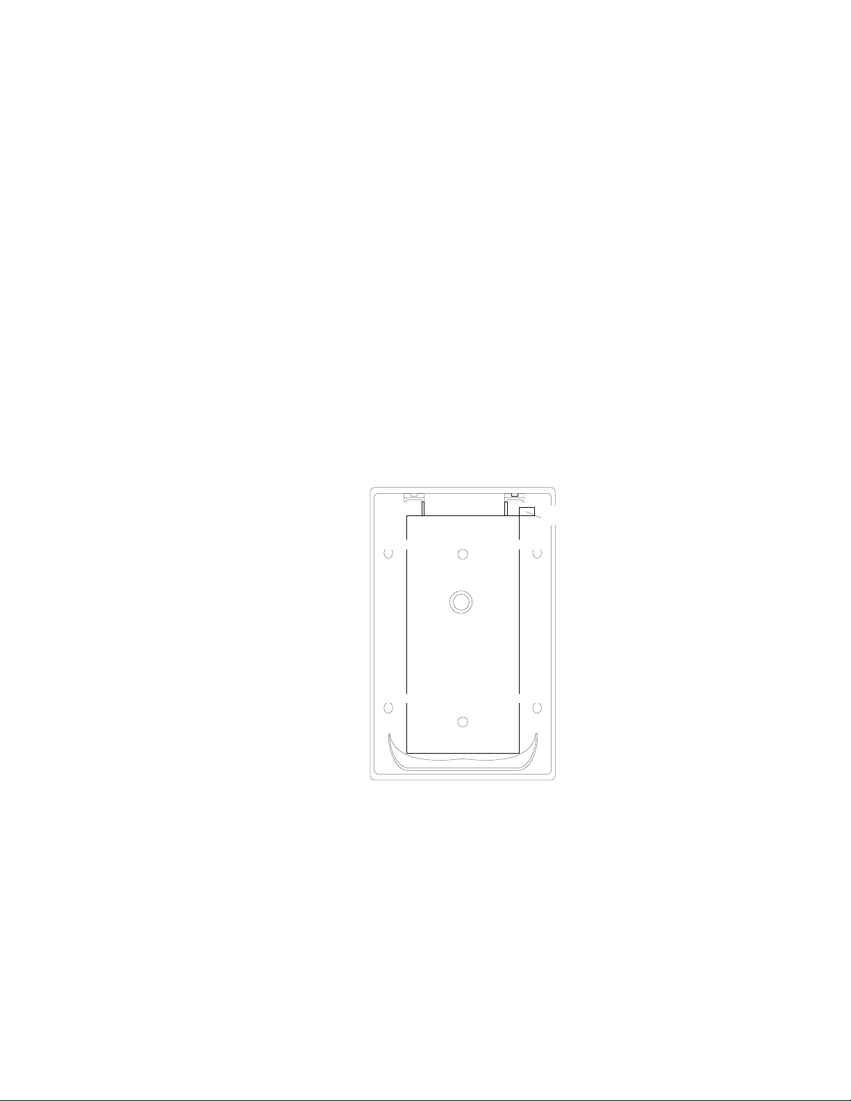
To mount the unit, first remove the cover by inserting a small screwdriver into the notch at the bottom of the
cover and prying up. Next, remove the circuit board/mirror unit from the enclosure. Unscrew the set screw
near the reset button enough to allow it to clear the stop block in the housing. Push the unit toward the top of
the enclosure until it clears the four retainer tabs. Then lift the board/mirror unit out of the enclosure.
For surface or corner mounting, open two holes in the rear housing. Mark the location for the mounting
screws, using the enclosure as a template. Pre-start the mounting screws.
Firmly mount the detector. Replace the circuit board/mirror assembly.
© 1996 Inovonics W i rel ess Corporation
02154b.doc LIT-FA206DS-INSTALL hc:7-Aug-01
2
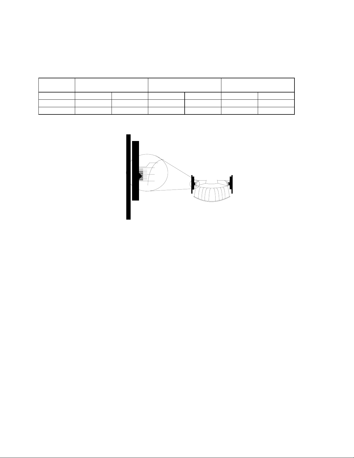
Mirror Assembly Adjustment:
!"
Set Vertical angle based on the following table. The table indicates setting for mirror type, mounting
height and desired range. Vertical angle calibration markings are on the mirror. Slide the mirror forward
or back until the angle hash marks are in line with the markers on each side of the frame.
Mounting
Height
6'6"(2m)
7'6"(2.3m)
8'6"(2.6m)
Broad Mirror
30'(9m) 50'(15m)
Barrier Mirror
50'(15m) 80'(25m)
Long Range Mirror
80'(25m) 120'(36m)
-6# -3# -3# -2# -2# -1#
-8# -5# -5# -3# -3# -2#
-9# -6# -6# -4# -4# -2#
+2
0
-8
-16
+2
0
-8
-16
+2
0
-8
-16
!"
Adjust Horizontal angle of the mirror assembly, if necessary. Rotate the assembly from side to side until
aimed in the desired direction.
!"
After the unit has been programmed and installed, follow instructions for setup and walk testing the unit.
Range and coverage can be adjusted by changing mirror angle setting.
!"
Optional accessories including the B328 Gimbal Mount and the B335 Low Profile Mount permit the
FA206DS to be mounted in many locations and aimed to permit desired coverage.
© 1996 Inovonics W i rel ess Corporation
02154b.doc LIT-FA206DS-INSTALL hc:7-Aug-01
3
 Loading...