


FA206B
Frequency Agile®
Passive InfraRed Motion Detector
900MHz Transmitter
Installation Instructions
03814A
Overview:
The FA206B is an Inovonics transmitter incorporating the Detection Systems RF940U PIR. The
unit operates on a single 3.0V lithium battery (Panasonic CR123A or equivalent). The PIR is
designed to detect indoor movement of human-size infrared targets. With Detection Systems’ Pet
Friendly
total weight.
Features:
x
x
x
®
feature the sensor will not detect single or multiple animals up to 30 pounds (13.6 Kg)
Inovonics' reliable 900 Megahertz
Mounting options permit flat wall, corner or hallway mounting. Optional bracket for special mounting.
RF interference immunity.
Frequency Agile
®
radio link.
Specifications:
Dimensions: 4.5" H x 2.5” W x 1.6” D (11.4 cm x 6.4 cm x 4.1 cm)
Operating temperature: 32qF to 120qF (0qC to 49qC)
Humidity: 0 – 85% non-condensing (PIR)
Battery: 1 - 3.0V lithium ( Panasonic CR123A, Duracell DL123A)
Note: Battery is always supervised
Tamper: Housing and wall (optional)
PIR RF interference immunity: Greater than 30 v/m 26 MHz – 1 GHz
Mounting Height: 7 to 9 feet (2.1 to 2.7 meters)
Alarm lockout time: 3 minutes
Options: B335 Swivel and B338 Ceiling mounting brackets
(from Detection Systems)
Important Notes
n
These products are designed to be installed and maintained by professional security technicians.
n
Products, unless specifically noted, are intended for indoor use.
n
Manually test all products regularly.
© 2003 Inovonics W i rel ess Corporation
03814a.doc LIT-FA206DS-INSTALL hc:24-Apr-03
1
Installation:
Mounting Note: Recommended mounting height range is 7 to 9 feet (2.1 to 2.7 meters).
General mounting advice:
x
For best detection, locate the FA206B so that intruders move
across
detection coverage patterns,
rather than toward or away from the sensor.
x
The mounting surface should be solid and vibration-free.
x
Check areas for potential sources of false alarms. Remember that the sensor responds to quick
changes in heat patterns within its coverage pattern. Avoid locating it where it is exposed to direct or
reflected sunlight, or to objects which can be heated quickly by sunlight. Do not place the FA206B facing
windows. Don't place it near heating or cooling sources, like heater ducts or air conditioners, which
might direct hot or cold air onto the sensor. Look for appliances such as space heaters which can
rapidly heat up. Moving objects, such as ceiling fans are also potential sources of false alarms.
x
Find out about normal use of the area. Are there pets? Might there be birds or rodents, for example, in a
warehouse? Configure the FA206B accordingly.
x
When the sensor might detect users who enter the protected area through a delayed door, program the
sensor as a "Follower" device.
x
Make end-users aware of the location of the FA206B and caution them about obstructing the coverage
pattern when re-arranging furniture or stock.
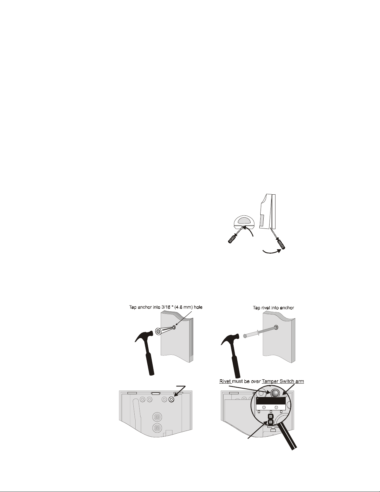
Mounting Instructions:
To mount the unit, first remove the cover by inserting a
small screwdriver into the notch at the bottom of the
cover and prying up.
If using the
wall tamper
feature, install a wall anchor and rivet as shown below.
If not using the wall tamper, drill at mounting locations as indicated.
Important: remove the wall tamper jumper to enable the tamper feature.
PIR Botto m
Insert screwdriver here
Pry gently
© 2003 Inovonics W i rel ess Corporation
Knockout for Rivet
Wall Tamper enabled
(Jumper off)
03814a.doc LIT-FA206DS-INSTALL hc:24-Apr-03
2
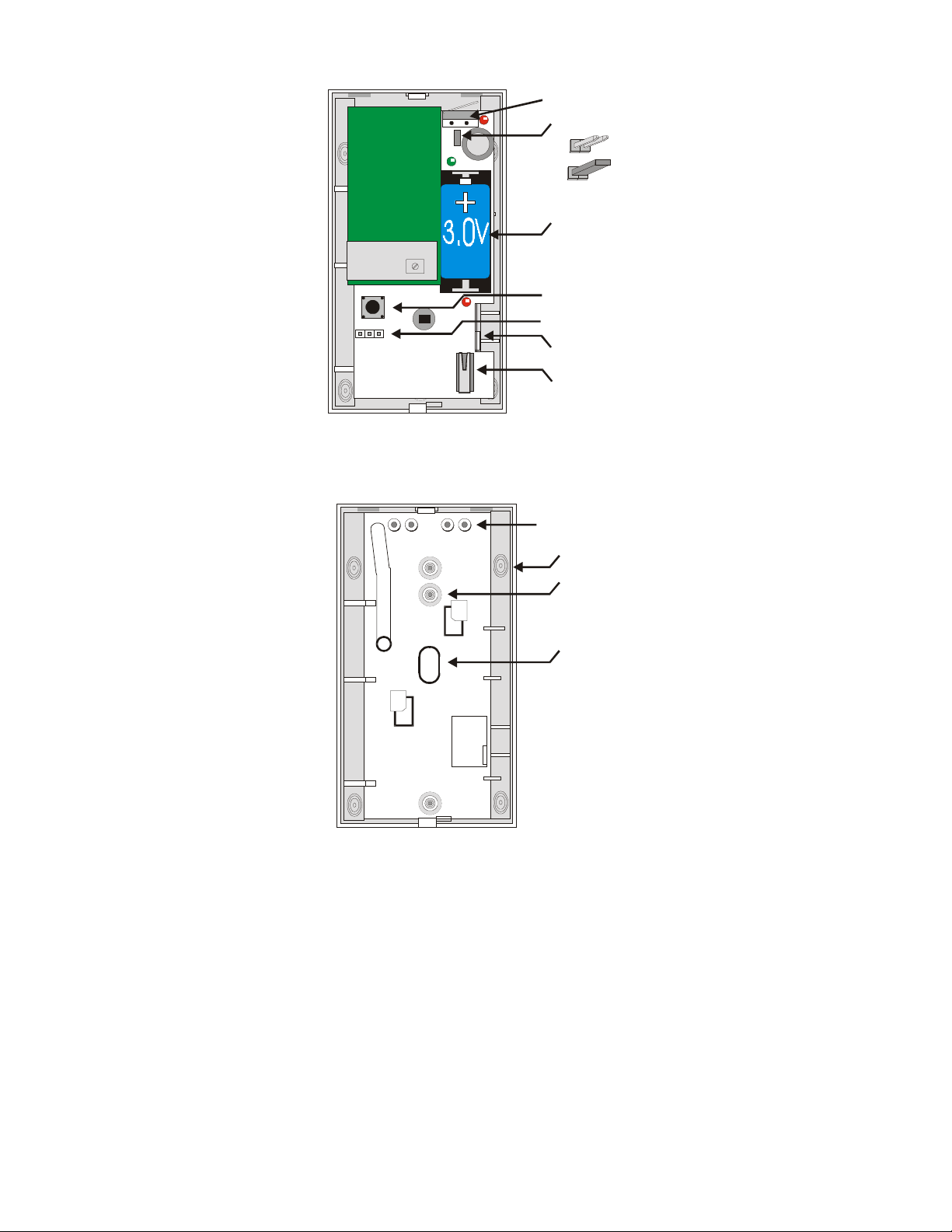
Next, remove the circuit board / mirror unit from the enclosure. Pull the PCB locking tab toward the side of
the housing, then lift the board / mirror unit out of the enclosure.
Wall Tamper Switch
Wall Tamper Jumper
Wireless
Transmitter
Jumper Off = Enabled
Jumper On = Disabled
PCB
Battery
Reset Switch
Programming Jumper
PCB Locking T ab
Housing Tamper Swi t c h
For surface or corner mounting, drill two holes in the housing. Mark the location for the mounting screws,
using the enclosure as a template. Pre-start the mounting screws. Firmly mount the detector. Replace the
circuit board/mirror assembly.
Knockout for Wall Tamper (1 pl)
Corner Mount (4 pl)
Flat Surface Mount (3 pl)
Areas to remove if using
the B335 Bracket (3 pl)
Important!
Do not overtighten mounting screws!
Cover may not attach correctly.
© 2003 Inovonics W i rel ess Corporation
03814a.doc LIT-FA206DS-INSTALL hc:24-Apr-03
3
 Loading...