

PRODUCT SUMMARY
The FA202 Smoke Detector is a supervised wireless, battery powered photoelectric smoke sensor. The sensor includes a builtin sounder for alarm alerts, a visual status LED (light-emitting diode), and an Inovonics Wireless Frequency Agile®
transmitter. The FA202 communicates with all FA-series Inovonics Wireless Frequency Agile receivers as featured in
Inovonics’ Wireless Guardian and Vision Plus systems; and as integrated with systems manufactured by Digital Monitoring
Products, Bosch Security Systems, and Verex Monitor Integrated Security Management. Inovonics FA-series slave receivers can
function as stand-alone systems or can be integrated with many other security systems and panels.
Under normal (non-alarm) conditions, the LED flashes once every 8 seconds while the sensor monitors the surrounding
conditions. When the sensor detects smoke, the LED changes from flashing to on and the built-in sounder produces a loud
temporal beeping pattern. The sensor also transmits an alarm signal, which the panel receives and processes accordingly. The
smoke sensor uses two 3-volt lithium batteries, which are included.
The smoke sensor also provides the following features: • Self-diagnostics monitor sensor sensitivity and operational status.
See
Testing the FA202
. • Replaceable optical chamber for easy maintenance when required. See
Maintaining the System
.
I
NSTALLATION G
UIDELINES
For your information, the National Fire Protection Association’s Standard 72 reads as follows:
“2-2.1.1.1 Smoke detectors shall be installed outside of each separate sleeping area in the immediate vicinity of the bedrooms and on each additional story of the family
living unit including basements and excluding crawl spaces and unfinished attics. In new construction, a smoke detector shall be installed in each sleeping room.”
“A-2.5.2.1 Smoke Detection--Are More Smoke Detectors Desirable? The required number of smoke detectors might not provide reliable early warning protection for those areas
separated by a door from the areas protected by the required smoke detectors. For this reason, it is recommended that the householder consider the use of additional smoke
detectors for those areas for increased protection. The additional areas include the basement bedrooms, dining room, furnace room, utility room, and hallways not protected
by the required smoke detectors. The installation of smoke detectors in kitchens, attics (finished or unfinished), or garages is not normally recommended, as these locations
occasionally experience conditions that can result in improper operation.”
Recommended:
Install a minimum of two smoke sensors in any household. • Put a smoke sensor in
the hallway outside of every bedroom area. A minimum of two smoke sensors are required in homes
with two bedroom areas. • Put a smoke sensor on every level of a multi-level residence. • In rooms
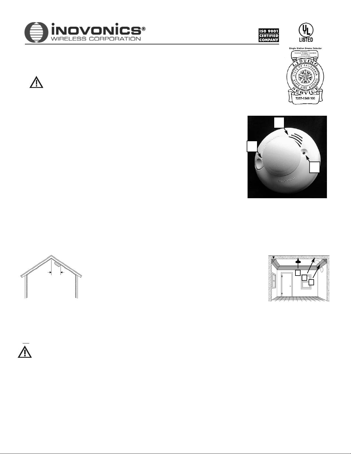
with sloped ceilings, install smoke sensors 0.9m (3 feet) measured down from the highest point of
the ceiling. (Figure 2.) • Install basement sensors on the ceiling as close to the center of the room
as possible (Figure 3-F). If this is not practical, install it on the ceiling no closer than 10cm (4
inches) from any wall or corner (Figure 3-G). • DO NOT mount a smoke sensor to a drop-ceiling tile;
mount it to a metal runner. • If ceiling mounting is not practical, install on an inside wall between
10 an 15cm (4 and 6 inches) from the ceiling (Figure 3-H). • Put smoke sensors at both ends of a
bedroom hallway if the hallway is more than 9m (30 feet) long. Large rooms over 84 square meters
(900 square feet) require more than a single sensor. • Areas with rough ceilings or short, transomtype walls coming down from the ceiling require additional smoke sensors. • Install second-floor
smoke sensors on the ceiling at the top of the first-to-second floor stairwell. Be sure that no door or other obstruction blocks the path of smoke to the sensor.
I
MPORTANT ! Regulations pertaining to smoke sensor installations
vary. For more information, contact your local fire department or local authority having jurisdiction.
Doo Noot Loocate SSensoors:
• In or near areas such as kitchens or garages, where smoke or vehicle exhausts normally occur. (Protect these areas with heat-detection devices.) •
Near furnaces, hot water heaters, or gas space heaters. • In damp or very humid areas, or next to bathrooms with showers. Install sensors at least 1.5m (5 feet)
away from bathrooms. • In very cold or very hot areas. • In dusty, dirty, or insect infested areas. • Near fresh air inlets or returns or excessively drafty areas. Air
conditioners, heater, fans, and fresh air intakes and returns can drive smoke away from smoke sensors. • In dead air spaces at the top of a peaked ceiling or wall/
ceiling intersect. Dead air may prevent smoke from reaching a smoke sensor. • Near flourescent light fixtures. Install smoke sensors at least 3m (10 feet) away from
flourescent light fixtures.
Liimiitatiioons:
Smoke alarms can significantly help in reducing loss, injury and even death. However, no matter how reliable a detection device is, no warning system works
perfectly under every circumstance. Users are advised that smoke alarms cannot ensure protection from any or
all damage or loss.
All sensors are subject to possible compromise or failure-to-warn for a variety of reasons. For example: • Smoke sensors cannot detect smoke in chimneys, walls, roofs, or
smoke blocked by a closed door. • Sensors may not detect smoke on other levels of the building. • Sensors may not warn in time when fires are caused by smoking in bed,
explosions, improper storage of flammables, overloaded electrical circuits, or other hazardous conditions. • Smoke alarms may not be heard by sound sleepers or by
individuals affected by alcohol, drugs or medications. •
This device is not designed for the hearing impaired.
• Smoke alarms may not provide warning early enough: they
activate only when smoke reaches the sensor, so smoke from fires starting away from the immediate vicintity of the device may not reach the alarm at all, or may be
detected too late for timely evacuation.
02873E - 1
© 2006 Inovonics Wireless Corporation
Figure 3: Smoke sensor mounting
locations
Figure 2: Sloped, peaked
or gabled ceilings.
.9M (3FT)
FA202 Frequency Agile®900MHz Smoke Detector
Installation and Operation Manual - 02873E
IMPORTANT NOTES
TTHHIISS EEQQUUIIPPMMEENNTT SSHHOOUULLDD BBEE IINNSSTTAALLLLEEDD IINN AACCCCOORRDDAANNCCEE WWIITTHH TTHHEE NNAATTIIOONNAALL FFIIRREE PPRROOTTEECCTTIIOONN AASSSSOOCCIIAATTIIOONN’’SS SSTTAANNDDAARRDD 7722..
• These products are designed to be installed and maintained by professional security technicians.
• Products, unless specifically noted, are intended for indoor use.
• Manually test all products regularly.
• All wiring to be used must be in accordance with the provisions of Article 210 of the National Electrical Code, ANSI/NFPA
70.
• It is the responsibility of individuals in the household that are capable of assisting others to provide assistance to those
who may not be awakened by the alarm sound, or to those who may be incapable of safely evacuating the area unassisted.
F
G
H
Figure 1: Sensor Features
A--Test/Silence Button B--Sounder Vent C--LED
A
B
C
EVACUATION PLANS
Develop plans for a variety of emergency situations. Periodically discuss and rehearse emergency plans that include the following:
• Know which doors and windows are normally locked, open, closed.
• Feel closed doors. If they feel hot, find another escape route.
• Teach all occupants to escape as quickly as possible. Do not stop to gather belongings.
• During your escape, crawl and hold your breath as much as possible to minimize smoke inhalation.
• Meet at a designated outdoor location.
• Insist that no one should return to the premises if there is a fire.
• Notify the fire department from a neighbor’s phone or by cell phone from outside the residence.
• Prepare a drawing of escape routes, using the following guidelines. See Figure 4.
• Show all building levels.
• Show all exits. (Two exits per room are recommended.)
• Show the location of all components of the fire alarm system.
• Show the locations of any fire extinguishers, hoses, ladders, etc.
PROGRAMMING THE FA202
Program the FA202 prior to installation. If units are programmed offsite, they should be repackaged with batteries installed and the red dust cover in place.
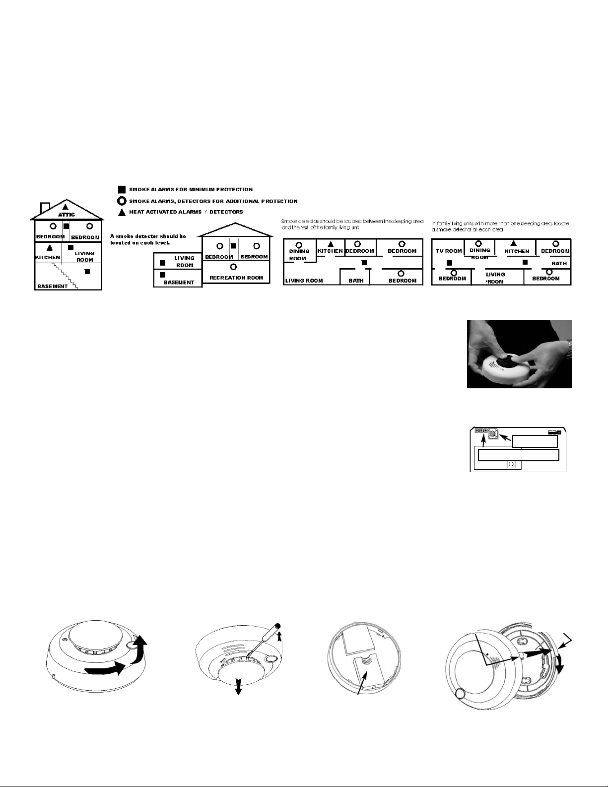
(1) Locate the transmitter programming pins by disassembling the detector. (a) Remove the red dust cover containing the
batteries from the smoke detector. (b) With the smoke detector facing you, remove the detector body from its Mounting
Base by twisting the detector about 15 degrees counterclockwise with respect to the Mounting Base. See Figure 7. (c)
Remove the Sensor Cap by first sliding a flatblade screwdriver part way into the slot on the side of the Cap. See Figure 8.
Now, gently push the handle down while twisting the Sensor Cap counter-clockwise with respect to the Sensor. See
Figure 5. (d) Remove the Sensor from the Body by pushing down on the Smoke Chamber while pulling up on the bottom of
the body. See Figure 5. (e) Remove the Battery Cover that encloses the Battery Compartment by pushing on the area
marked OPEN. See Figure 9. (f) Take the batteries out of the red dust cover holder and load them into the Battery
Compartment. Make sure to observe battery polarity and make sure the battery removal ribbon rests under the batteries. (g)
Refer to Figure 6 to locate the programming pins on the transmitter board.
(2) Using an appropriate Inovonics programming device, set the programming options as follows:
External Switch Type: Normally Closed
EOL Resistor: No
Use Internal Contact: No
Check-in Time: 60 seconds
(3) When prompted by the programming device to plug in the transmitter, connect the programming cable to the 3-pin header.
See Figure 6. (Orientation of the cable with respect to the 3-pin header is not important; both outside pins on the 3-pin header are at ground potential.)
(4) Press the Reset button on the transmitter. See Figure 6.
When programming is complete, disconnect the cable, test the detector per the
Sensitivity Test
procedure, and reassemble the smoke detector.
Note: The FA202 retains registration data in non-vvolatile memory.
It does not require re-programming after loss of power. Install a new battery and press the reset
button to re-initialise the transmitter and restore registration.
Figure 9: Battery compartment
Figure 7: Removing cover from base.
Alignment Tab
Alignment Slot
Figure 10: Cover-to-base assembly :
Align tab with slot and twist clockwise
Figure 4: Example of a floorplan
02873E - 2
Figure 5: Removing the sensor
from the detector body
Programming pins
Reset Button
Figure 6: Transmitter board
Figure 8: Removing the sensor cap
 Loading...