

Ingersoll-Rand WSC092H, WSC048H, WSC072E, WSC090E, WSC072H Installation, Operation And Maintenance Manual
...Page 1
Installation, Operation,
and Maintenance
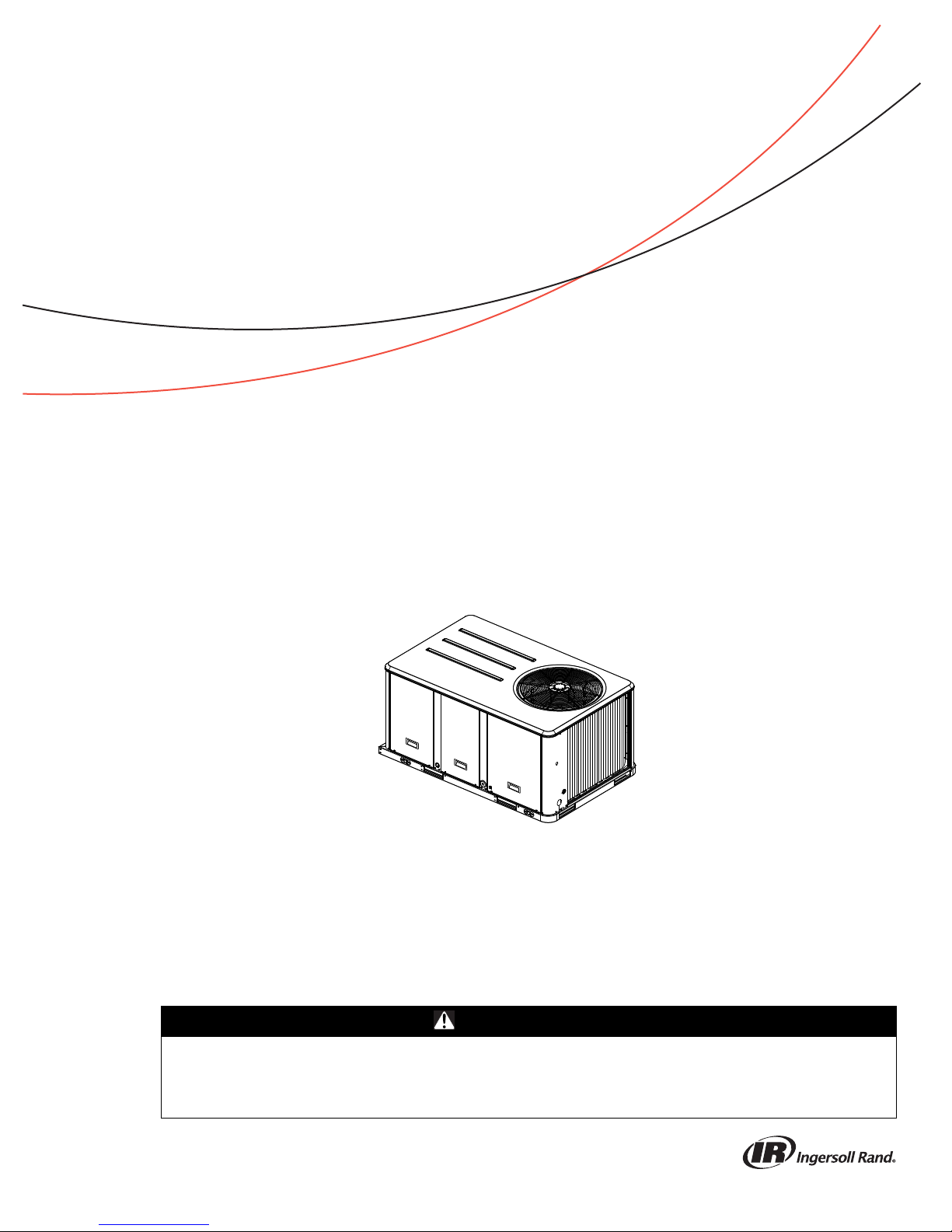
Packaged Rooftop Air Conditioners
Precedent™ — Heat Pump
3 to 10 Tons — 60 Hz
Model Numbers
Only qualified personnel should install and service the equipment. The installation, starting up, and servicing
of heating, ventilating, and air-conditioning equipment can be hazardous and requires specific knowledge and
training. Improperly installed, adjusted or altered equipment by an unqualified person could result in death or
serious injury. When working on the equipment, observe all precautions in the literature and on the tags,
stickers, and labels that are attached to the equipment.
April 2018
WSC036H-WSC060H
WSC072H, WSC090E, WSC102H & WSC120H
W/DHC036H-W/DHC060H
SAFETY WARNING
RT-SVX23M-EN
Page 2
Introduction
Read this manual thoroughly before operating or servici ng
this unit.
Warnings, Cautions, and Notices
Safety advisories appear throughout this manual as
required. Your personal safety and the proper operation of
this machine depend upon the strict observance of these
precautions.
The three types of advisories are defined as follows:
WARNING
CAUTIONs
NOTICE:
Important Environmental Concerns
Scientific research has shown that certain man-made
chemicals can affect the earth’s naturally occurring
stratospheric ozone layer when released to the
atmosphere. In particular, several of the identified
chemicals that may affect the ozone layer are refrigerants
that contain Chlorine, Fluorine and Carbon (CFCs) and
those containing Hydrogen, Chlorine, Fluorine and
Carbon (HCFCs). Not all refrigerants containing these
compounds have the same potential impact to the
environment. Trane advocates the responsible handling of
all refrigerants-including industry replacements for CFCs
and HCFCs such as saturated or unsaturated HFCs and
HCFCs.
Important Responsible Refrigerant
Practices
Trane believes that responsible refrigerant practices are
important to the environment, our customers, and the air
conditioning industry. All technicians who handle
refrigerants must be certified according to local rules. For
the USA, the Federal Clean Air Act (Section 608) sets forth
the requirements for handling, reclaiming, recovering and
recycling of certain refrigerants and the equipment that is
used in these service procedures. In addition, some states
or municipalities may have additional requirements that
must also be adhered to for responsible management of
refrigerants. Know the applicable laws and follow them.
Indicates a potentially hazardous
situation which, if not avoided, could
result in death or serious injury.
Indicates a potentially hazardous
situation which, if not avoided, could
result in minor or moderate injury. It
could also be used to alert against
unsafe practices.
Indicates a situation that could result in
equipment or property-damage only
accidents.
WARNI NG
Proper Field Wiring and Grounding
Required!
Failure to follow code could result in death or serious
injury. All field wiring MUST be performed by qualified
personnel. Improperly installed and grounded field
wiring poses FIRE and ELECTROCUTION hazards. To
avoid these hazards, you MUST follow requirements for
field wiring installation and grounding as described in
NEC and your local/state electrical codes.
WARNI NG
Personal Protective Equipment (PPE)
Required!
Failure to wear proper PPE for the job being undertaken
could result in death or serious injury. Technicians, in
order to protect themselves from potential electrical,
mechanical, and chemical hazards, MUST follow
precautions in this manual and on the tags, stickers,
and labels, as well as the instructions below:
• Before installing/servicing this unit, technicians
MUST put on all PPE required for the work being
undertaken (Examples; cut resistant gloves/sleeves,
butyl gloves, safety glasses, hard hat/bump cap, fall
protection, electrical PPE and arc flash clothing).
ALWAYS refer to appropriate Material Safety Data
Sheets (MSDS)/Safety Data Sheets (SDS) and OSHA
guidelines for proper PPE.
• When working with or around hazardous chemicals,
ALWAYS refer to the appropriate MSDS/SDS and
OSHA/GHS (Global Harmonized System of
Classification and Labelling of Chemicals) guidelines
for information on allowable personal exposure
levels, proper respiratory protection and handling
instructions.
• If there is a risk of energized electrical contact, arc, or
flash, technicians MUST put on all PPE in accordance
with OSHA, NFPA 70E, or other country-specific
requirements for arc flash protection, PRIOR to
servicing the unit. NEVER PERFORM ANY
SWITCHING, DISCONNECTING, OR VOLTAGE
TESTING WITHOUT PROPER ELECTRICAL PPE AND
ARC FLASH CLOTHING. ENSURE ELECTRICAL
METERS AND EQUIPMENT ARE PROPERLY RATED
FOR INTENDED VOLTAGE.
© 2018 Ingersoll Rand RT-SVX23M-EN
Page 3
WARNING
Follow EHS Policies!
Failure to follow instructions below could result in
death or serious injury.
• All Ingersoll Rand personnel must follow Ingersoll
Rand Environmental, Health and Safety (EHS)
policies when performing work such as hot work,
electrical, fall protection, lockout/tagout, refrigerant
handling, etc. All policies can be found on the BOS
site. Where local regulations are more stringent than
these policies, those regulations supersede these
policies.
• Non-Ingersoll Rand personnel should always follow
local regulations.
Copyright
This document and the information in it are the property of
Trane, and may not be used or reproduced in whole or in
part without written permission. Trane reserves the right
to revise this publication at any time, and to make changes
to its content without obligation to notify any person of
such revision or change.
Introduction
Trademarks
All trademarks referenced in this document are the
trademarks of their respective owners.
Revision History
Updated to include new WSC102H, WSC120H
RT-SVX23M-EN 3
Page 4

Table of Contents
Model Number Descriptions . . . . . . . . . . . . . . 6
Model Number Notes . . . . . . . . . . . . . . . . 7
General Information . . . . . . . . . . . . . . . . . . . . . 8
Unit Inspection . . . . . . . . . . . . . . . . . . . . . . 8
Storage . . . . . . . . . . . . . . . . . . . . . . . . . . . . 8
Unit Nameplate . . . . . . . . . . . . . . . . . . . . . 8
Compressor Nameplate . . . . . . . . . . . . . . . 8
Unit Description . . . . . . . . . . . . . . . . . . . . . 8
Economizer Control Actuator (Optional) . 8
System Input Devices & Functions . . . . . . 9
Low Pressure Control . . . . . . . . . . . . . . . . . 9
High Pressure Control . . . . . . . . . . . . . . . 10
Power Exhaust Control (Optional) . . . . . 10
Lead/Lag Control (Dual Circuit Only) . . . 10
Pre-Installation . . . . . . . . . . . . . . . . . . . . . . . . . 12
Dimensions and Weights . . . . . . . . . . . . . . . . 13
Installation . . . . . . . . . . . . . . . . . . . . . . . . . . . . . 20
Foundation . . . . . . . . . . . . . . . . . . . . . . . . . . 20
Horizontal Units . . . . . . . . . . . . . . . . . . . . 20
Ductwork . . . . . . . . . . . . . . . . . . . . . . . . . . 20
Roof Curb . . . . . . . . . . . . . . . . . . . . . . . . . 21
Rigging . . . . . . . . . . . . . . . . . . . . . . . . . . . 22
General Unit Requirements . . . . . . . . . . . . 23
Factory Installed Economizer . . . . . . . . . 23
Temperature Limit Switch Usage for Electric
Heat Units . . . . . . . . . . . . . . . . . . . . . . . . . 23
Horizontal Discharge Conversion WSC036H,
WSC048H,
W/DHC036H
. . . . . . . . . . . . . . . . . . . . . . . . . . 23
Horizontal Discharge Conversion WSC060H120E/H, W/DHC048-120H
TCO-A Instructions . . . . . . . . . . . . . . . . . . 25
Return Air Smoke Detector . . . . . . . . . . . 25
. . . . . . . . . . . . . . . 24
Air-Fi™ Wireless Communication Interface 26
Main Electrical Power Requirements . . . . 27
Through-the-Base Gas Installation . . . . . . 27
Requirements for Gas Heat . . . . . . . . . . . . 27
Electric Heat Requirements . . . . . . . . . . . 28
Low Voltage Wiring
(AC & DC) Requirements . . . . . . . . . . . . . 28
Condensate Drain Configuration . . . . . . . . .28
Filter Installation . . . . . . . . . . . . . . . . . . . . .29
Field Installed Power Wiring . . . . . . . . . . . .29
Standard Wiring . . . . . . . . . . . . . . . . . . . . . 29
Optional TBUE Wiring (Through-the-Base
Electrical Option) . . . . . . . . . . . . . . . . . . . .29
Field Installed Control Wiring . . . . . . . . . . 30
Controls Using 24 VAC . . . . . . . . . . . . . . .30
Controls Using DC Analog Input/Outputs
(Standard Low Voltage Multiconductor Wire)
30
Space Temperature Averaging (ReliaTel™
only) . . . . . . . . . . . . . . . . . . . . . . . . . . . . . .33
Pre-Start . . . . . . . . . . . . . . . . . . . . . . . . . . . . . . . .37
Voltage Imbalance . . . . . . . . . . . . . . . . . . . . .37
Electrical Phasing (Three Phase Motors) . .37
Compressor Crankcase Heaters . . . . . . . .38
ReliaTel™ Controls . . . . . . . . . . . . . . . . . . 38
Test Modes . . . . . . . . . . . . . . . . . . . . . . . . . . .39
Unit Start-Up . . . . . . . . . . . . . . . . . . . . . . . . . . . .41
Sequence of Operation . . . . . . . . . . . . . . . . . . .41
ReliaTel™ Controls . . . . . . . . . . . . . . . . . . 41
ReliaTel™ Controls - Constant Volume (CV)
41
ReliaTel™ Control Cooling without an Econo-
mizer . . . . . . . . . . . . . . . . . . . . . . . . . . . . . .41
Three-Stages of Cooling . . . . . . . . . . . . . .41
ReliaTel™ Control Evaporator Fan Operation
(for Gas Units) . . . . . . . . . . . . . . . . . . . . . .41
ReliaTel™ Control Evaporator Fan Operation
(for Cooling Only Units) . . . . . . . . . . . . . . . 42
Low Ambient Operation . . . . . . . . . . . . . .42
Multi-Speed Indoor Motor . . . . . . . . . . . . .42
Fan Output% . . . . . . . . . . . . . . . . . . . . . . . . 42
Multi-Zone VAV Sequence of Operation . .42
Supply Air Pressure Control . . . . . . . . . . .42
Supply Air Static Pressure Limit . . . . . . . .43
Supply Air Temperature Controls . . . . . . .43
Supply Air Setpoint Reset . . . . . . . . . . . . .43
Zone Temperature Control . . . . . . . . . . . .43
4 RT-SVX23M-EN
Page 5

Table of Contents
Variable Air Volume Applications (Single
Zone VAV)
Discharge Air Cool Setpoint Adjustment 44
ReliaTel™ Control Cooling with an Economiz-
er . . . . . . . . . . . . . . . . . . . . . . . . . . . . . . . . 44
ReliaTel™ Control Dehumidification . . . 45
Dehumidification Coil Purge Cycle . . . . . 45
ReliaTel™ Control Cooling with an Economiz-
er . . . . . . . . . . . . . . . . . . . . . . . . . . . . . . . . 45
Economizer Set-Up . . . . . . . . . . . . . . . . . 46
ReliaTel™ Control Heating Operation (for
Cooling Only Units) . . . . . . . . . . . . . . . . . 46
ReliaTel™ Control Heating Operation (for Gas
Units) . . . . . . . . . . . . . . . . . . . . . . . . . . . . . 46
Ignition Module . . . . . . . . . . . . . . . . . . . . 46
Drain Pan Condensate Overflow Switch (Op-
tional) . . . . . . . . . . . . . . . . . . . . . . . . . . . . 47
. . . . . . . . . . . . . . . . . . . . . . . . . . . 44
Sequence of Operation - Heat Pumps . . . . . 48
Heating Operation . . . . . . . . . . . . . . . . . . . . 48
Demand Defrost . . . . . . . . . . . . . . . . . . . . . . 48
Emergency Heat Operation . . . . . . . . . . . . 48
Verifying Proper Air Flow . . . . . . . . . . . . . . 48
Units with 5-Tap Direct Drive Indoor Fan 48
Units with Belt Drive Indoor Fan . . . . . . . 49
Units with Constant CFM Direct Drive Indoor
Fan . . . . . . . . . . . . . . . . . . . . . . . . . . . . . . . 49
3 to 5 Ton 17 Plus/WHC/DHC units with the
constant CFM direct drive indoor fan . . . 49
ReliaTel™ Units Equipped with Direct Drive
Indoor Plenum Fan (optional except for 10
Ton Units) . . . . . . . . . . . . . . . . . . . . . . . . . 50
Return Air Smoke Detector . . . . . . . . . . . 51
Economizer Start-Up . . . . . . . . . . . . . . . . 51
Compressor Start-Up . . . . . . . . . . . . . . . . 52
Heating Start-Up . . . . . . . . . . . . . . . . . . . . 52
Final System Setup . . . . . . . . . . . . . . . . . 53
Heating Season . . . . . . . . . . . . . . . . . . . . .55
Coil Cleaning . . . . . . . . . . . . . . . . . . . . . . . 56
Troubleshooting . . . . . . . . . . . . . . . . . . . . . . . . .58
ReliaTel™ Control . . . . . . . . . . . . . . . . . . . . .58
System Status Checkout Procedure . . . . . .58
Method 1 . . . . . . . . . . . . . . . . . . . . . . . . . . . 58
Resetting Cooling and Heating Lockouts .59
Zone Temperature Sensor (ZTS) Service Indicator
. . . . . . . . . . . . . . . . . . . . . . . . . . . . . . . . .60
Clogged Filter Switch . . . . . . . . . . . . . . . . . 60
Fan Failure Switch . . . . . . . . . . . . . . . . . . .60
Condensate Overflow Switch . . . . . . . . . .60
Zone Temperature Sensor (ZTS) Test . . . .60
Test 1 Zone Temperature Thermistor
(ZTEMP) . . . . . . . . . . . . . . . . . . . . . . . . . . .60
Test 2 Cooling Set Point (CSP) and Heating
Set Point (HSP) . . . . . . . . . . . . . . . . . . . . . .60
Test 3 System Mode and Fan Selection . .60
Test 4 LED Indicator Test, (SYS ON, HEAT,
COOL & SERVICE) . . . . . . . . . . . . . . . . . . .60
Programmable & Digital Zone
Sensor Test . . . . . . . . . . . . . . . . . . . . . . . . .61
Mixed Air Temperature Low Limit Diagnostic
63
Troubleshooting Procedures for Direct Drive
Plenum Fan
. . . . . . . . . . . . . . . . . . . . . . . . . . .63
Wiring Diagrams . . . . . . . . . . . . . . . . . . . . . . . .64
Limited Warranty . . . . . . . . . . . . . . . . . . . . . . . .66
Heat Pump WCD, WCH, WSC, WHC and DHC
(Parts Only) . . . . . . . . . . . . . . . . . . . . . . . . .66
Models Less Than 20 Tons for Commercial
Use* . . . . . . . . . . . . . . . . . . . . . . . . . . . . . .66
Maintenance . . . . . . . . . . . . . . . . . . . . . . . . . . . 54
Fan Belt Adjustment - Belt Drive Units . . . 54
Monthly Maintenance . . . . . . . . . . . . . . . . . 55
Filters . . . . . . . . . . . . . . . . . . . . . . . . . . . . . 55
Return Air Smoke Detector Maintenance 55
Condensate Overflow Switch . . . . . . . . . 55
Cooling Season . . . . . . . . . . . . . . . . . . . . 55
RT-SVX23M-EN 5
Page 6

Model Number Descriptions
Digit 1 - Unit Type
W Packaged Heat Pump
D Dual Fuel Heat Pump
2
Digit 2 - Efficiency
S Standard Efficiency
HHigh Efficiency
Digit 3 - Airflow
C Convertible
Digit 4,5,6 - Nominal Gross
Cooling Capacity (MBh)
036 3 Ton
048 4 Ton
060 5 Ton
072 6 Ton
090 7.5 Ton
102 8.5 Ton
120 10 Ton
Digit 7 - Major Design Sequence
Digit 8 - Voltage Selection
3 208-230/60/3
4 460/60/3
W 575/60/3
Digit 9 - Unit Controls
R ReliaTel™ Microprocessor
Digit 10 - Heating Capacity
Note: Applicable to Digit 1,W models
0 No Electric Heat
B6 kW
C9 kW
E12 kW
G18 kW
J 23 kW
K 27 kW
N 36 kW
P 54 kW
Note: Applicable to Digit 1,D models
L Low Heat
M Medium Heat
H High Heat
X Low Heat, Stainless Steel Heat
Y Medium Heat, Stainless Steel Heat
Z High Heat, Stainless Steel Heat
only.
only
Exchanger
Exchanger
Exchanger
Digit 11 - Minor Design
Sequence
A First Sequence
Digit 12,13 - Service Sequence
** Factory Assigned
Digit 14 - Fresh Air Selection
0No Fresh Air
A Manual Outside Air Damper 0-50%
B Motorized Outside Air Damper
C Economizer, Dry Bulb 0-100%
D Economizer, Dry Bulb 0-100%
10
0-50%
without Barometric Relief
with Barometric Relief
4
4
E Economizer, Reference Enthalpy
0-100% without Barometric Relief
F Economizer, Reference Enthalpy
0-100% with Barometric Relief
G Economizer, Comparative
Enthalpy 0-100% without
Barometric Relief
4
H Economizer, Comparative
Enthalpy 0-100% with Barometric
4
Relief
K Low Leak Economizer with
Barometric Relief
M Low Leak Economizer with Reference
Enthalpy with Barometric Relief
P Low Leak Economizer with
Comparative Enthalpy with
Barometric Relief
1
4
4
Digit 15 - Supply Fan/Drive Type/
Motor
0 Standard Drive
1 Oversized Motor
2 Optional Belt Drive Motor
6 Single Zone Variable Air
Vol u m e (SZVAV)
7 Multi-Speed Indoor Fan
8 Single Zone Variable Air Volume
(SZVAV) w/Oversized Motor
E Multi-Zone Variable Air Volume
(MZVAV)
F Multi-Zone Variable Air Volume
(MZVAV) w/Oversized Motor
3
3
14
12
14
14
14
Digit 16 - Hinged Service
Access/Filters
0 Standard Panels/Standard Filters
A Hinged Access Panels/Standard
Filters
B Standard Panels/2” MERV 8 Filters
C Hinged Access Panels/2” MERV 8
Filters
D Standard Panels/2” MERV 13 Filters
E Hinged Access Panels/2” MERV 13
Filters
Digit 17 - Condenser Coil
Protection
0 Standard Coil
1 Standard Coil with Hail Guard
2 Black Epoxy Pre-Coated Condenser
Coil
3 Black Epoxy Pre-Coated
Condenser Coil with Hail Guard
Digit 18 - Through-the-Base
Provisions
0 No Through-the-Base Provisions
A Through-the-Base Electric
5
Digit 19 - Disconnect/Circuit
Breaker (three-phase only)
0 No Disconnect/No Circuit Breaker
1 Unit Mounted Non-Fused
Disconnect
2 Unit Mounted Circuit Breaker
5
5
Digit 20 - Convenience Outlet
0 No Convenience Outlet
A Unpowered Convenience Outlet
B Powered Convenience Outlet
(three-phase only)
6
Digit 21 - Communications
Options
0 No Communications Interface
1 Trane® Communications Interface
2 LonTalk® Communications Interface
6 BACnet® Communications Interface
7 Air-Fi™ Wireless Communications
15
Digit 22 - Refrigeration System
Option
0 Standard Refrigeration System
7
Digit 23 - Refrigeration Controls
0 No Refrigeration Control
1Frostat™
11
2 Crankcase Heater
3 Frostat and Crankcase Heater
2
16
11 ,16
Digit 24 - Smoke Detector
0 No Smoke Detector
A Return Air Smoke Detector
B Supply Air Smoke Detector
C Supply and Return Air Smoke
Detectors
8
D Plenum Smoke Detector
8
Digit 25 - System Monitoring
Controls
0 No Monitoring Control
1 Clogged Filter Switch
2 Fan Failure Switch
3 Discharge Air Sensing Tube
4 Clogged Filter Switch and Fan
Fail Switch
5 Clogged Filter Switch and Discharge
Air Sensing Tube
6 Fan Fail Switch and Discharge Air
Sensing Tube
7 Clogged Filter and Fan Fail Switches
and Discharge Air Sensing Tube
A Condensate Drain Pan Overflow
Switch
B Clogged Filter Switch and
Condensate Drain Pan Overflow
Switch
C Fan Failure Switch and Condensate
Drain Pan Overflow Switch
D Discharge Air Sensing and
Condensate Drain Pan Overflow
Switch
E Clogged Filter Switch, Fan Failure
Switch and Condensate Drain Pan
Overflow Switch
F Clogged Filter Switch, Discharge
Air Sensing Tube and Condensate
Drain Pan Overflow Switch
G Fan Failure Switch, Discharge Air
6 RT-SVX23M-EN
Page 7

Model Number Descriptions
Sensing Tube and Condensate
Drain Pan Overflow Switch
H Clogged Filter Switch, Fan Failure
Switch, Discharge Air Sensing
and Condensate Drain Pan Overflow
Switch
Digit 26 - System Monitoring
Controls
0 No Monitoring Controls
A Demand Control Ventilation (CO
B Low Leak Economizer with FDD
(Fault Detection & Diagnostics)
C FDD (Fault Detection & Diagnostics)
with DCV (Demand Control
Ventilation)
13
)
2
Digit 27 - Unit Hardware
Enhancements
0 No Enhancements
1 Stainless Steel Drain Pan
Digit 31 - Advanced Unit
Controls
0 Standard Unit Controls
1 Human Interface
Model Number Notes
1. Manual outside air damper will
ship factory supplied within the
unit, but must be field installed.
2. High pressure control is standard
on all units.
3. Multi-stage, direct drive standard
on 3 to 5 ton models. Belt drive
standard on 6 to 8.5 ton standard
efficiency models. Variable speed
direct drive standard on 10 ton
model.
4. Economizer with barometric
relief is for downflow configured
units only. Order economizer
without barometric relief for
horizontal configuration.
Barometric relief for horizontal
configured units must be ordered
as field installed accessory.
5. Through-the-base electric
required when ordering
disconnect/circuit breaker
options.
6. Requires use of disconnect or
circuit breaker.
7. Standard metering devices are
TXVs.
8. The return air smoke detector
may not fit up or work properly on
the Precedent™ units when used
in conjunction with 3rd party
accessories such as bolt on heat
wheels, economizers and power
exhaust. Do not order the return
air smoke detectors when using
this type of accessory.
9. Requires hinged access panels.
10. Motorized outside air damper is
not available on Multi-Speed or
SZVAV (Single Zone Variable Air
Vol ume)
Variable Air Volume)
or MZVAV (Multi Zone
products.
11. Frostat™ standard on multispeed and SZVAV (single zone
variable air volume)
products.
12. Multi-speed indoor fan only
available on 8.5 and 10 ton
products.
13. Demand control ventilation
option includes wiring only. The
sensor is a field-installed
CO
2
only option.
14. SZVAV/MZVAV available only on
3 to 5 tons high efficiency and
SZVAV available on 8.5 and 10 ton
standard efficiency unit.
15. Must be used with BACnet® open
protocol.
16. Crankcase heater is standard on
all heat pumps.
RT-SVX23M-EN 7
Page 8

General Information
Unit Inspection
As soon as the unit arrives at the job site
• Verify that the nameplate data matches the data on the
sales order and bill of lading (including electrical data).
• Verify that the power supply complies with the unit
nameplate specifications.
• Visually inspect the exterior of the unit, including the
roof, for signs of shipping damage.
If the job site inspection of the unit reveals damage or
material shortages, file a claim with the carrier
immediately. Specify the type and extent of the damage on
the “bill of lading” before signing.
• Visually inspect the internal components for shipping
damage as soon as possible after delivery and before
it is stored. Do not walk on the sheet metal base pans.
• If concealed damage is discovered, notify the carrier’s
terminal of damage immediately by phone and by
mail. Concealed damage must be reported within 15
days.
• Request an immediate joint inspection of the damage
by the carrier and the consignee. Do not remove
damaged material from the receiving location. Take
photos of the damage, if possible. The owner must
provide reasonable evidence that the damage did not
occur after delivery.
• Notify the appropriate sales representative before
installing or repairing a damaged unit.
Storage
Take precautions to prevent condensate from forming
inside the unit’s electrical compartments and motors if:
1. the unit is stored before it is installed; or,
2. the unit is set on the roof curb, and temporary heat is
provided in the building. Isolate all side panel service
entrances and base pan openings (e.g., conduit holes,
Supply Air and Return Air openings, and flue
openings) from the ambient air until the unit is ready
for start-up.
Note: Do not use the unit’s heater for temporary heat
without first completing the start-up procedure
detailed under the Unit Start-Up chapter.
The manufacturer will not assume any responsibility for
equipment damage resulting from condensate
accumulation on the unit’s electrical and/or mechanical
components.
Unit Nameplate
A Mylar unit nameplate is located on the unit’s corner
support next to the filter access panel. It includes the unit
model number, serial number, electrical characteristics,
refrigerant charge, as well as other pertinent unit data.
Compressor Nameplate
The nameplate for the compressors are located on the side
of the compressor.
Unit Description
Before shipment, each unit is leak tested, dehydrated,
charged with refrigerant and compressor oil, and run
tested for proper control operation.
The condenser coils are aluminum fin, mechanically
bonded to copper tubing.
Direct-drive, vertical discharge condenser fans are
provided with built-in thermal overload protection.
The ReliaTel™ Control Module is a microelectronic control
system that is referred to as “Refrigeration Module”
(RTRM). The acronym RTRM is used extensively
throughout this document when referring to the control
system network.
These modules through proportional/integral control
algorithms perform specific unit functions that governs
unit operation in response to; zone temperature, supply air
temperature, and/or humidity conditions depending on
the application. The stages of capacity control for these
units is achieved by starting and stopping the
compressors.
The RTRM is mounted in the control panel and is factory
wired to the respective internal components. The RTRM
receives and interpret information from other unit
modules, sensors, remote panels, and customer binary
contacts to satisfy the applicable request for cooling.
Economizer Control Actuator (Optional)
The ECA monitors the mixed air temperature, return air
temperature, minimum position setpoint (local or
remote), power exhaust setpoint, CO
ambient dry bulb/enthalpy sensor or comparative
humidity (return air humidity against ambient humidity)
sensors, if selected, to control dampers to an accuracy of
+/- 5% of stroke. The actuator is spring returned to the
closed position any time that power is lost to the unit. It is
capable of delivering up to 25 inch pounds of torque and
is powered by 24 VAC.
RTCI - ReliaTel™ Trane® Communication
Interface (Optional)
This module is used when the application calls for an
ICSTM building management type control system. It
allows the control and monitoring of the system through
an ICS panel. The module can be ordered from the factory
or ordered as a kit to be field installed. Follow the
installation instruction that ships with each kit when field
installation is necessary.
setpoint, CO2, and
2
8 RT-SVX23M-EN
Page 9

General Information
RLCI - ReliaTel™ LonTalk® Communication
Interface (Optional)
This module is used when the application calls for an
ICSTM building management type control system that is
LonTalk. It allows the control and monitoring of the system
through an ICS panel. The module can be ordered from the
factory or ordered as a kit to be field installed. Follow the
installation instruction that ships with each kit when field
installation is necessary.
RBCI - ReliaTel™ BACnet® Communications
Interface (Optional)
This module is used when the application calls for an open
BACnet protocol. It allows the control and monitoring of
the system through an ICS panel. The module can be
ordered from the factory or as a kit to be field installed.
Follow the installation instructions that ships with each kit
when field installation is necessary.
RTOM – ReliaTel™ Options Module
The RTOM monitors the supply fan proving, clogged filter,
supply air temperature, exhaust fan setpoint, supply air
tempering, Frostat™ and smoke detector. Refer to system
input devices and functions for operation.
This module is standard on 10 ton products.
System Input Devices & Functions
The RTRM must have a zone sensor or thermostat input in
order to operate the rooftop unit. The flexibility of having
several mode capabilities depends upon the type of zone
sensor thermostat selected to interface with the RTRM.
The descriptions of the following basic Input Devices used
within the RTRM network are to acquaint the operator with
their function as they interface with the various modules.
Refer to the unit’s electrical schematic for the specific
module connections.
The following controls are available from the factory for
field installation.
Supply Fan Failure Input (Optional)
The Fan Failure Switch can be connected to sense indoor
fan operation:
FFS (Fan Failure Switch) If air flow through the unit is not
proven by the differential pressure switch connected to the
RTRM (factory set point 0.07 “w.c.) within 40 seconds
nominally, the RTRM will shut off all mechanical
operations, lock the system out, send a diagnostic to ICS,
and the SERVICE output will flash. The system will remain
locked out until a reset is initiated either manually or
through ICS.
Clogged Filter Switch (Optional)
The unit mounted clogged filter switch monitors the
pressure differential across the return air filters. It is
mounted in the filter section and is connected to the
RTOM. A diagnostic SERVICE signal is sent to the remote
RT-SVX23M-EN 9
panel if the pressure differential across the filters is at least
0.5" w.c. The contacts will automatically open when the
pressure differential across the filters decreases to
approximately 0.4" w.c. The clogged filter output is
energized when the supply fan is operating and the
clogged filter switch has been closed for at least 2 minutes.
The system will continue to operate regardless of the
status of the filter switch.
Note: On units equipped with factory installed MERV 13
filters, a clogged filter switch with different
pressure settings will be installed. This switch will
close when the differential pressure is
approximately 0.8' w.c. and open when the
differential falls to 0.7" w.c.
Condensate Drain Pan Overflow Switch
(Optional)
ReliaTel™ Option
This input incorporates the Condensate Overflow Switch
(COF) mounted on the drain pan and the ReliaTel Options
Module (RTOM). When the condensate level reaches the
trip point for 6 continuous seconds, the RTOM will shut
down all unit functions until the overflow condition has
cleared. The unit will return to normal operation after 6
continuous seconds with the COF in a non-tripped
condition. If the condensate level causes unit shutdown
more than 2 times in a 3 days period, the unit will be
locked-out of operation requiring manual reset of
diagnostic system through Zone Sensor or Building
Automation System (BAS). Cycling unit power will also
clear the fault.
Compressor Disable (CPR1/2)
This input incorporates the low pressure control (LPC) of
each refrigeration circuit and can be activated by opening
a field supplied contact installed on the LTB.
If this circuit is open before the compressor is started, the
compressor will not be allowed to operate. Anytime this
circuit is opened for 1 continuous second during
compressor operation, the compressor for that circuit is
immediately turned “Off”. The compressor will not be
allowed to restart for a minimum of 3 minutes should the
contacts close.
If four consecutive open conditions occur during the first
three minutes of operation, the compressor for that circuit
will be locked out, a diagnostic communicated to the
remote panel (if installed), and a manual reset will be
required to restart the compressor.
Low Pressure Control
When the LPC is opened for 1 continuous second, the
compressor for that circuit is turned off immediately. The
compressor will not be allowed to restart for a minimum
of 3 minutes.
If four consecutive open conditions occur during an active
call for cooling, the compressor will be locked out, a
diagnostic communicated to ICS™, if applicable, and a
Page 10

General Information
manual reset required to restart the compressor. On dual
compressor units only the affected compressor circuit is
locked out.
High Pressure Control
The high pressure controls are wired in series between the
compressor outputs on the RTRM and the compressor
contactor coils. If the high pressure control switch opens,
the RTRM senses a lack of current while calling for cooling
and locks the compressor out.
If four consecutive open conditions occur during an active
call for cooling, the compressor will be locked out, a
diagnostic communicated to ICS™, if applicable, and a
manual reset required to restart the compressor. On dual
compressor units only the affected compressor circuit is
locked out.
Power Exhaust Control (Optional)
The power exhaust fan is started whenever the position of
the economizer dampers meets or exceed the power
exhaust setpoint when the indoor fan is on.
The setpoint panel is located in the return air section and
is factory set at 25%.
Lead/Lag Control (Dual Circuit Only)
Lead/Lag is a selectable input located on the RTRM. The
RTRM is configured from the factory with the Lead/Lag
control disabled. To activate the Lead/Lag function, simply
cut the wire connected to J3-8 at the RTRM. When it is
activated, each time the designated lead compressor is
shut off due to the load being satisfied, the lead
compressor or refrigeration circuit switches. When the
RTRM is powered up, i.e. after a power failure, the control
will default to the number one circuit compressor.
Zone Sensor Module (ZSM) (BAYSENS107*)
This electronic sensor features three system switch
settings (Heat, Cool, and Off) and two fan settings (On and
Auto). It is a manual changeover control with single
setpoint. (Cooling Setpoint Only)
Zone Sensor Module (ZSM) (BAYSENS109*)
This electronic sensor features four system switch settings
(Heat, Cool, Auto, and Off) and two fan settings (On and
Auto). It is a manual or auto changeover control with dual
setpoint capability. It can be used with a remote zone
temperature sensor BAYSENS077*.
Programmable Zone Sensor - (BAYSENS119*)
This 7 day programmable sensor features 2, 3 or 4 periods
for Occupied or Unoccupied programming per day. If the
power is interrupted, the program is retained in
permanent memory. If power is off for an extended period
of time, only the clock and day may have to be reset.
The zone sensor allows selection of 2, 3 or 4 system modes
(Heat, Cool, Auto, and Off), two fan modes (On and Auto).
It has dual temperature selection with programmable start
time capability.
The occupied cooling set point ranges between 45 and 98
degrees Fahrenheit. The heating set point ranges between
43 and 96 degrees Fahrenheit.
A liquid crystal display (LCD) displays zone temperature,
temperature set points, day of the week, time, and
operational mode symbols.
The Option Menu is used to enable or disable applicable
functions, i.e.; Morning Warm-up, Economizer minimum
position override during unoccupied status, Fahrenheit or
Centigrade, Supply air tempering, Remote zone
temperature sensor, 12/24 hour time display, Smart fan,
and Computed recovery.
During an occupied period, an auxiliary relay rated for 1.25
amps @ 30 volts AC with one set of single pole double
throw contacts is activated.
Status Inputs (4 Wires Optional). The ZSM can be wired to
receive four (4) operating status signals from the RTRM
(HEAT, COOL, SYSTEM “ON”, SERVICE). Four (4) wires
from the RTRM should be connected to the appropriate
terminals (7, 8, 9 & 10) on the ZSM.
Remote Zone Sensor (BAYSENS073*)
This electronic sensor features remote zone sensing and
timed override with override cancellation. It is used with a
Trane Integrated Comfort™ building management
system.
Remote Zone Sensor (BAYSENS074*)
This electronic sensor features single setpoint capability
and timed override with override cancellation. It is used
with a Trane Integrated Comfort™ building management
system.
Remote Zone Sensor (BAYSENS016*)
This bullet type temperature sensor can be used for;
outside air (ambient) sensing, return air temperature
sensing, supply air temperature sensing, remote
temperature sensing (uncovered). Wiring procedures vary
according to the particular application and equipment
involved. Refer to the unit’s wiring diagrams for proper
connections.
Remote Zone Sensor (BAYSENS077*)
This electronic sensor can be used with BAYSENS106*,
108*, 110*, 119* Remote Panels. When this sensor is wired
to a BAYSENS119* remote panel, wiring must be 18 AWG
shielded twisted pair (Belden 8760 or equivalent). Refer to
the specific remote panel for wiring details.
Wireless Zone Sensor (BAYSENS050*)
This electronic sensor features five system settings (Auto,
Off, Cool, Heat, and Emergency Heat) and with On and
Auto fan settings. It is a manual or auto changeover control
with dual setpoint capability. Other features include a
timed override function, lockable system settings, and
10 RT-SVX23M-EN
Page 11

General Information
Fahrenheit or Celsius temperature display. Included with
the wireless zone sensor will be a receiver that is to be
mounted inside the unit, a mounting bracket, and a wire
harness.
High Temperature Sensor (BAYFRST001*)
This sensor connects to the RTRM Emergency Stop Input
located on the LTB and provides high limit “shutdown” of
the unit and requires a manual reset. The sensor is used to
detect high temperatures due to fire in the air conditioning
or ventilation ducts. The sensor is designed to mount
directly to the sheet metal duct. Each kit contains two
sensors. The return air duct sensor (X1310004001) is set to
open at 135°F. The supply air duct sensor (X1310004002) is
set to open at 240°F. The control can be reset after the
temperature has been lowered approximately 25°F below
the cutout setpoint.
Evaporator Frost Control
This input incorporates the Frostat™ control (FOS) located
on the indoor coil and can be activated by closing a field
supplied contact installed in parallel with the FOS.
If this circuit is closed before the compressor is started, the
compressor will not be allowed to operate. Anytime this
circuit is closed for 1 continuous second during
compressor operation, the compressor for that circuit is
immediately turned “Off”. The compressor will not be
allowed to restart for a minimum of 3 minutes should the
FOS open.
Frostat™ is standard on multi-speed indoor motors and
single zone VAV products (SZVAV).
Smoke Detector Sensor (Optional)
This sensor is only applicable on units equipped with a
RTOM. It provides high limit “shutdown” of the unit and
requires a manual reset. The sensor is used to detect
smoke due to fire in the air conditioning or ventilation
ducts.
Important:
• The supply air smoke detector samples supply air. The
return and plenum air smoke detectors sample return
air. The smoke detectors are designed to shut off the
unit if smoke is sensed in the supply air stream or
return air stream. This function is performed by
sampling the airflow entering the unit at the return air
opening. Follow the instructions provided below to
assure that the airflow through the unit is sufficient for
adequate sampling. Failure to follow these instructions
will prevent the smoke detectors from performing it's
design function.
• Airflow through the unit is affected by the amount of
dirt and debris accumulated on the indoor coil and
filters. To insure that airflow through the unit is
adequate for proper sampling by the return air smoke
detector, complete adherence to the maintenance
procedures, including recommended intervals
between filter changes, and coil cleaning is required.
• Periodic checks and maintenance procedures must be
performed on the smoke detector to insure that it will
function properly. For detailed instructions concerning
these checks and procedures, refer to the appropriate
section(s) of the smoke detector Installation and
Maintenance Instructions provided with the literature
package for this unit.
In order for the supply air smoke detector or return air
smoke detector to properly sense smoke in the supply air
stream or return air stream, the air velocity entering the
smoke detector unit must be between 500 and 4000 feet
per minute. Equipment covered in this manual will
develop an airflow velocity that falls within these limits
over the entire airflow range specified in the evaporator
fan performance tables.
Phase Monitoring protection
Precedent units with 3-phase power are equipped with
phase monitoring protection as standard. These devices
protect motors and compressors against problems caused
by phase loss, phase imbalance, and phase reversal
indication.
This sensor monitors voltage between the 3 conductors of
the 3 phase power supply. Two LED lights are provided.
The green light indicates that a balanced 3 phase supply
circuit is properly connected. The red light indicates that
unit operation has been prevented. There are two
conditions that will prevent unit operation. The power
supply circuit is not balanced with the proper phase
sequence of L1, L2, L3 for the 3 conductors of a 3 phase
circuit. The line to line voltage is not between 180 volts and
633 volts.
Human Interface - 5 Inch Color Touchscreen
(Optional)
The 5 inch Color Touchscreen Human Interface provides an
intuitive user interface to the rooftop unit that speeds up
unit commissioning, shortens unit troubleshooting times,
and enhances preventative maintenance measures. The
human interface includes several features including:
• Data trending capabilities by means of time series
graphs
• Historical alarm messages
• Real-time sensor measurements
• On board system setpoints
• USB port that enables the downloading of component
runtime information as well as trended historical
sensor data
• Customized reports
RT-SVX23M-EN 11
Page 12
Pre-Installation
WARNI NG
Fiberglass Wool!
Exposition to glass wool fibers without all necessary
PPE equipment could result in cancer, respiratory, skin
or eye irritation, which could result in death or serious
injury. Disturbing the insulation in this product during
installation, maintenance or repair will expose you to
airborne particles of glass wool fibers and ceramic
fibers known to the state of California to cause cancer
through inhalation. You MUST wear all necessary
Personal Protective Equipment (PPE) including gloves,
eye protection, a NIOSH approved dust/mist respirator,
long sleeves and pants when working with products
containing fiberglass wool.
Precautionary Measures
• Avoid breathing fiberglass dust.
• Use a NIOSH approved dust/mist respirator.
• Avoid contact with the skin or eyes. Wear long-sleeved,
loose-fitting clothing, gloves, and eye protection.
• Wash clothes separately from other clothing: rinse
washer thoroughly.
• Operations such as sawing, blowing, tear-out, and
spraying may generate fiber concentrations requiring
additional respiratory protection. Use the appropriate
NIOSH approved respiration in these situations.
First Aid Measures
Eye Contact - Flush eyes with water to remove dust. If
symptoms persist, seek medical attention.
Skin Contact - Wash affected areas gently with soap and
warm water after handling.
12 RT-SVX23M-EN
Page 13
Dimensions and Weights
WSC036-048H, W/DHC036H Units
WSC060-120E/H, W/DHC048-060H Units
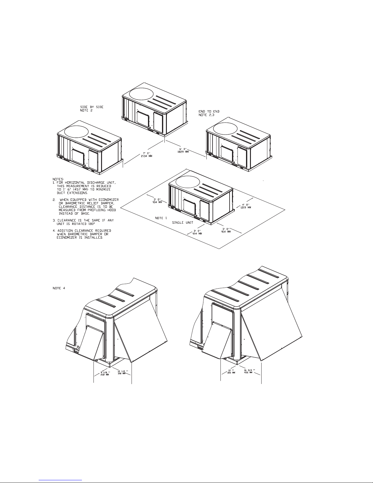
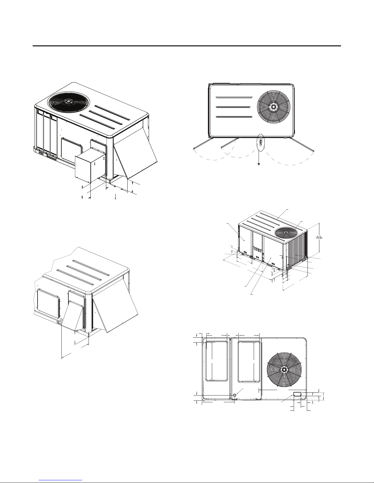
Figure 1. Typical installation clearances for single & multiple unit applications
RT-SVX23M-EN 13
Page 14
Dimensions and Weights
WARN ING
Heavy Objects!
Failure to follow instructions below or properly lift unit
could result in unit dropping and possibly crushing
operator/technician which could result in death or
serious injury, and equipment or property-only damage.
Ensure that all the lifting equipment used is properly
rated for the weight of the unit being lifted. Each of the
cables (chains or slings), hooks, and shackles used to
Improper Unit Lift!
Failure to properly lift unit could result in unit dropping
and possibly crushing operator/technician which could
result in death or serious injury, and equipment or
property-only damage. Test lift unit approximately 24
inches to verify proper center of gravity lift point. To
avoid dropping of unit, reposition lifting point if unit is
not level.
WARNI NG
lift the unit must be capable of supporting the entire
weight of the unit. Lifting cables (chains or slings) may
not be of the same length. Adjust as necessary for even
unit lift.
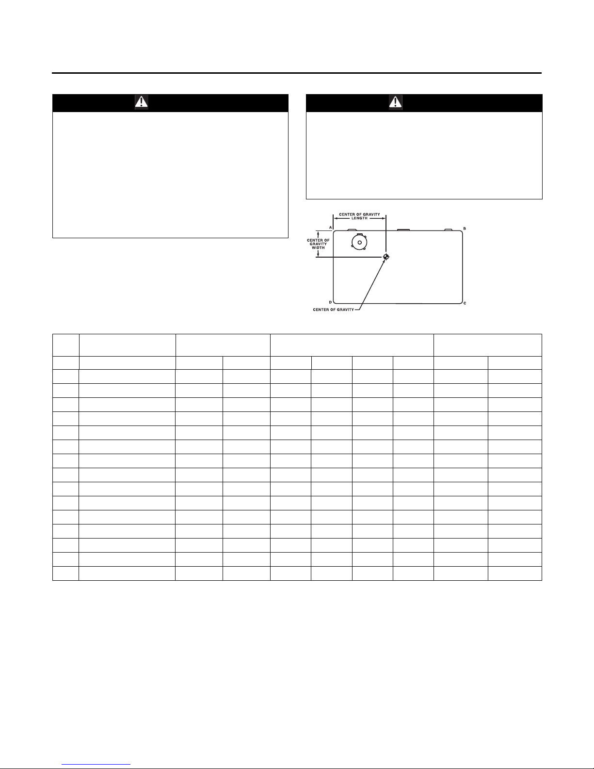
Table 1. Maximum unit & corner weights (lbs) and center of gravity dimensions (in.)
Unit
Tons Model No. Shipping Net A B C D Length Width
3 WSC036H 612 507 144 122 110 130 32 21
4 WSC048H 645 540 165 131 108 136 31 20
5 WSC060H 777 682 228 177 114 163 38 22
6 WSC072E/H 835 740 235 196 140 168 40 22
7.5 WSC090E/H 902 804 255 217 153 180 41 22
7.5 WSC092H 894 796 252 204 163 177 41 23
8.5 WSC102H 927 829 286 183 195 164 40 23
10 WSC120E 1388 1199 342 328 259 270 49 28
10 WSC120H 948 850 303 170 218 159 40 24
3 WHC036H 619 514 142 120 111 142 31 22
4 WHC048H 768 673 222 175 114 162 38 22
5 WHC060H 773 678 225 176 114 162 38 22
3 DHC036H 658 553 145 137 125 145 33 22
4 DHC048H 845 750 234 192 146 178 40 23
5 DHC060H 849 754 235 193 147 179 40 23
(a) Weights are approximate.
(b) Corner weights are given for information only.
Maximum Model
Weights
(a)
Corner Weights
(b)
Center of Gravity (in.)
14 RT-SVX23M-EN
Page 15
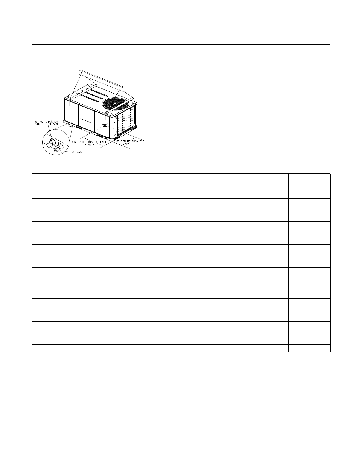
Figure 2. Rigging and center-of-gravity data
Dimensions and Weights
Table 2. Factory installed options (fiops)/accessory net weights (lbs)
WSC036H-048H,
W/DHC036H
Net Weight
Accessory
460V/575V IDM Transformer
Barometric Relief 7 10 10 10
Coil Guards 12 20 20 30
Economizer 26 36 36 36
Electric Heaters
Hinged Doors 11 12 12 12
Low Leak Economizer 68 93 93 93
Manual Outside Air Damper 16 26 26 26
Motorized Outside Air Damper 20 30 30 30
Oversized Motor 8 8 8 —
Powered Convenience Outlet 38 38 38 50
Powered Exhaust 40 80 80 80
Roof Curb 61 78 78 89
Smoke Detector, Supply 5 5 5 5
Smoke Detector, Return 7 7 7 7
Stainless Steel Heat Exchanger
Through-the-Base Electrical 8 13 8 13
Through-the-Base Gas(e) 55——
Unit Mounted Circuit Breaker 5 5 5 5
Unit Mounted Disconnect 5 5 5 5
(a) Weights for options not listed are <5 lbs.
(b) Net weight should be added to unit weight when ordering factory-installed accessories.
(c) Applicable to W/DHC 460/575V units.
(d) Applicable to heat pump units only (W*C).
(e) Applicable to dual fuel units only (D*C).
(d)
(c)
(e)
3 to 4 Tons
29 29 — —
15 30 30 40
45——
W/DHC048-060H
Net Weight
4 to 5 Tons
(a),(b)
WSC060H,
WSC072H-120E/H
Net Weight
6 to 10 Tons
W/DHC120H
Net Weight
10 Tons
RT-SVX23M-EN 15
Page 16
Dimensions and Weights
EVAPORATOR SECTION
ACCESS PANEL
ALTERNATE
CONDENSATE DRAIN
3/4 - 14 NPT DIA. HOLE
1/2 NPT GAS CONNECTION
TOP PANEL
CONDENSER FAN
CONDENSER COIL
UNIT CONTROL WIRE
7/8” (22 MM) DIA. HOLE
SERVICE GAUGE PORT ACCESS
1 3/8” (35 MM) DIA. HOLE
UNIT CONTROL WIRE
2” (51 MM) DIA. HOLE
40 7/8”
1038 MM
4 1/4”
108 MM
69 7/8”
1749 MM
42 1/4”
1073 MM
23 9/16”
598 MM
5 5/8”
143 MM
9 5/8”
244 MM
CONTROL AND COMPRESSOR
ACCESS PANEL
44 1/4”
1124 MM
7 5/8”
194 MM
5 9/16”
141 MM
4 1/4”
108 MM
20 1/4”
514 MM
THROUGH
THE BASE GAS
(Y_C/DHC MODELS ONLY)
THROUGH
THE BASE
ELECTRICAL
SUPPLY
RETURN
TBU CONDENSATE
3 5/8”
92 MM
14”
356 MM
9 1/4”
235 MM
15 1/2”
394 MM
4”
102 MM
24”
610 MM
18”
457 MM
27 9/16”
701 MM
4 3/16”
106 MM
4 9/16”
116 MM
23 1/2”
597 MM
2 13/16”
71 MM
6 1/2”
165 MM
3 11/16”
94 MM
4 7/8”
124 MM
5 1/16”
128 MM
9 15/16”
253 MM
SUPPLY
RETURN
3/4-14 NPT
DRAIN CONNECTION
CONDENSER COIL
17 1/4”
438 MM
8 7/8”
225 MM
13 1/4”
337 MM
23 1/4”
591 MM
3 3/16”
81 MM
14 3/4”
375 MM
4 3/4”
121 MM
CLEARANCE 36” (914 MM)
CLEARANCE 48” (1219 MM)
TYPICAL ROOF OPENING
CLEARANCE 36” (914 MM)
CLEARANCE FROM
TOP OF UNIT 72”
CLEARANCE
HORIZONTAL FLOW - 18” (457 MM)
DOWNFLOW 36” (914 MM)
68 3/16”
1732 MM
40”
1016 MM
37”
940 MM
44 1/2”
1130 MM
7
CLEARANCE 36” (914 MM)
CLEARANCE 36” (914 MM) FOR DOWNFLOW
CLEARANCE 18” (457 MM) FOR HORIZONTAL
CLEARANCE 36” (914 MM)
CLEARANCE 48” (1219 MM)
RETURN
SUPPLY
14”
356 MM
37 7/16”
951 MM
25 3/16”
640 MM
1 3/4”
44 MM
65 13/16”
1670 MM
1 3/4”
44 MM
14 9/16”
370 MM
8 3/8”
213 MM
61 13/16”
1568 MM
65 3/16”
1656 MM
16 3/4”
425 MM
2”
51 MM
2”
51 MM
40 7/8”
1038 MM
41 7/16”
1053 MM
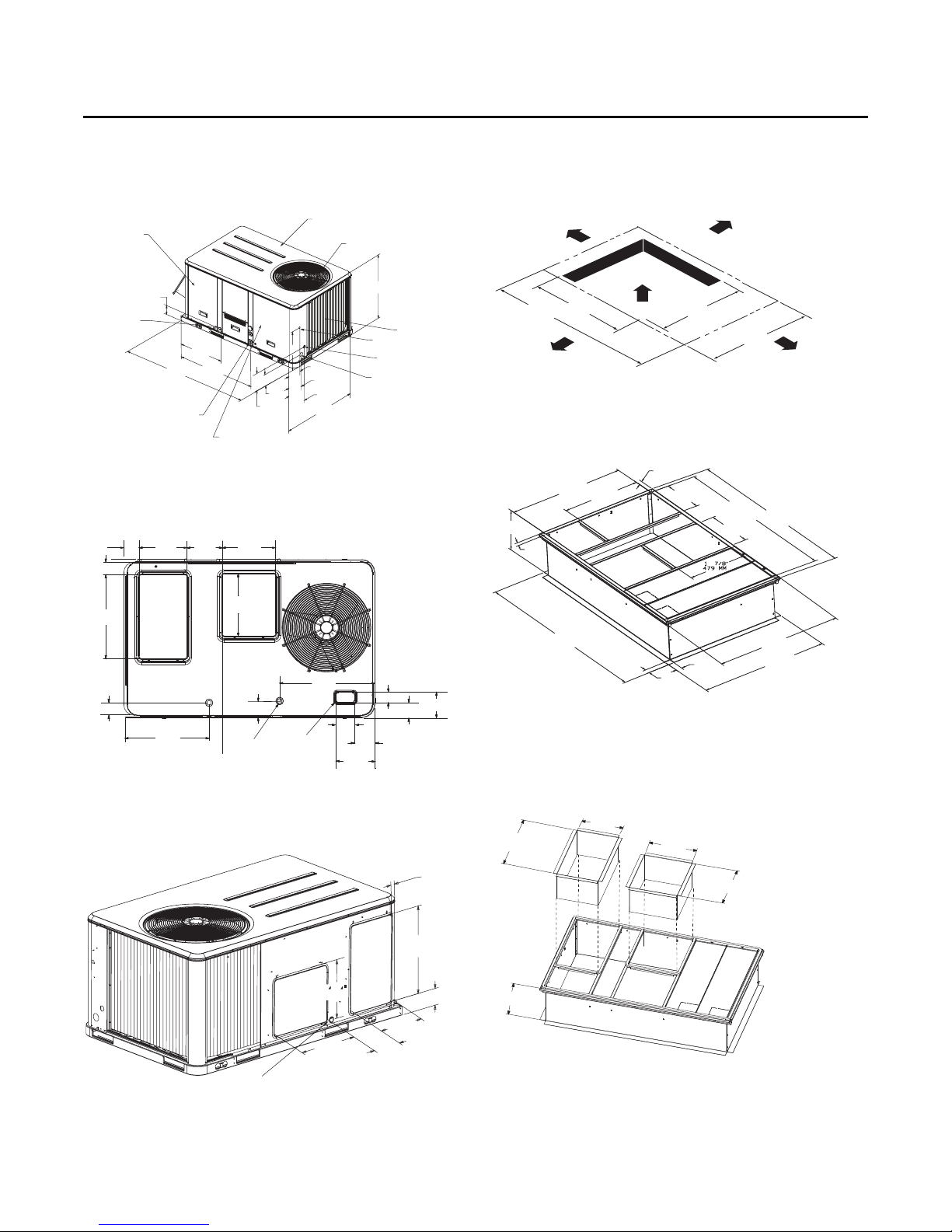
Figure 3. Heat pump - 3 to 4 tons standard efficiency, 3
ton high efficiency
Note: 2” electrical connection: single point power when heat installed
(WSC, W/DHC)
Figure 4. Heat pump - 3 to 4 tons standard efficiency, 3
ton high efficiency - downflow airflow supply/
return - through-the-base utilities
Figure 6. Heat pump - 3 to 4 tons standard efficiency, 3
ton high efficiency - unit clearance and roof
opening
Figure 7. Heat pump - 3 to 4 tons standard efficiency, 3
ton high efficiency - roof curb
Figure 5. Heat pump - 3 to 4 tons standard efficiency, 3
ton high efficiency - horizontal airflow supply/
return
16 RT-SVX23M-EN
Figure 8. Heat pump - 3 to 4 tons standard efficiency, 3
ton high efficiency - downflow duct
connections - field fabricated
Note: Reference tabular information for duct clearance to combustible
materials in the application consideration chapter.
14 1/16”
24 3/8”
(619 MM)
14”
(356 MM)
(357 MM)
RETURN
16 3/16”
(411 MM)
SUPPLY
17 1/16”
(433 MM)
ALL FLANGES 1 1/4” (32 MM)
Page 17
Dimensions and Weights
6 15/16”
176 MM
9 1/8”
232 MM
17 7/8”
454 MM
16”
406 MM
22 1/4”
565 MM
Applicable to
Y_C models only
EVAPORATOR SECTION
ACCESS PANEL
ALTERNATE CONDENSATE DRAIN
CONNECTION 3/4 - 14 NPT DIA. HOLE
4 1/4”
108 MM
27 5/8”
701 MM
47 7/8”
1216 MM
88 5/8”
2251 MM
18 1/2”
470 MM
9 5/8”
244 MM
5 5/8”
143 MM
1/2 NPT GAS CONNECTION
[60 MBh, 80 MBh, 100 MBh, 120 MBh,
130 MBh (not applicable to DHC)]
3/4 NPT GAS CONNECTION
(130 MBh (DHC only), 150 MBh, 200 MBh, 250 MBh)
CONTROL AND COMPRESSOR
ACCESS PANEL
4 1/4”
104 MM
5 5/8”
143 MM
7 5/8”
194 MM
53 1/4”
1353 MM
TOP PANEL
CONDENSER FAN
CONDENSER COIL
UNIT CONTROL WIRE
7/8” (22 MM) DIA. HOLE
SERVICE GAUGE PORT ACCESS
1 3/8” (35 MM) DIA. HOLE
UNIT POWER WIRE
1 3/8” (35 MM) DIA. HOLE
3 5/8”
92 MM
17 1/2”
444 MM
4”
102 MM
9 7/8”
251 MM
17 1/2”
444 MM
32 1/8”
816 MM
RETURN
SUPPLY
33”
838 MM
4 1/8”
104 MM
27 5/8”
701 MM
THROUGH THE
BASE CONDENSATE
40 3/4”
1035 MM
THROUGH THE
BASE ELECTRICAL
5 7/8”
149 MM
5”
127 MM
10 7/8”
276 MM
3 3/4”
95 MM
2 3/4”
71 MM
6 1/2”
165 MM
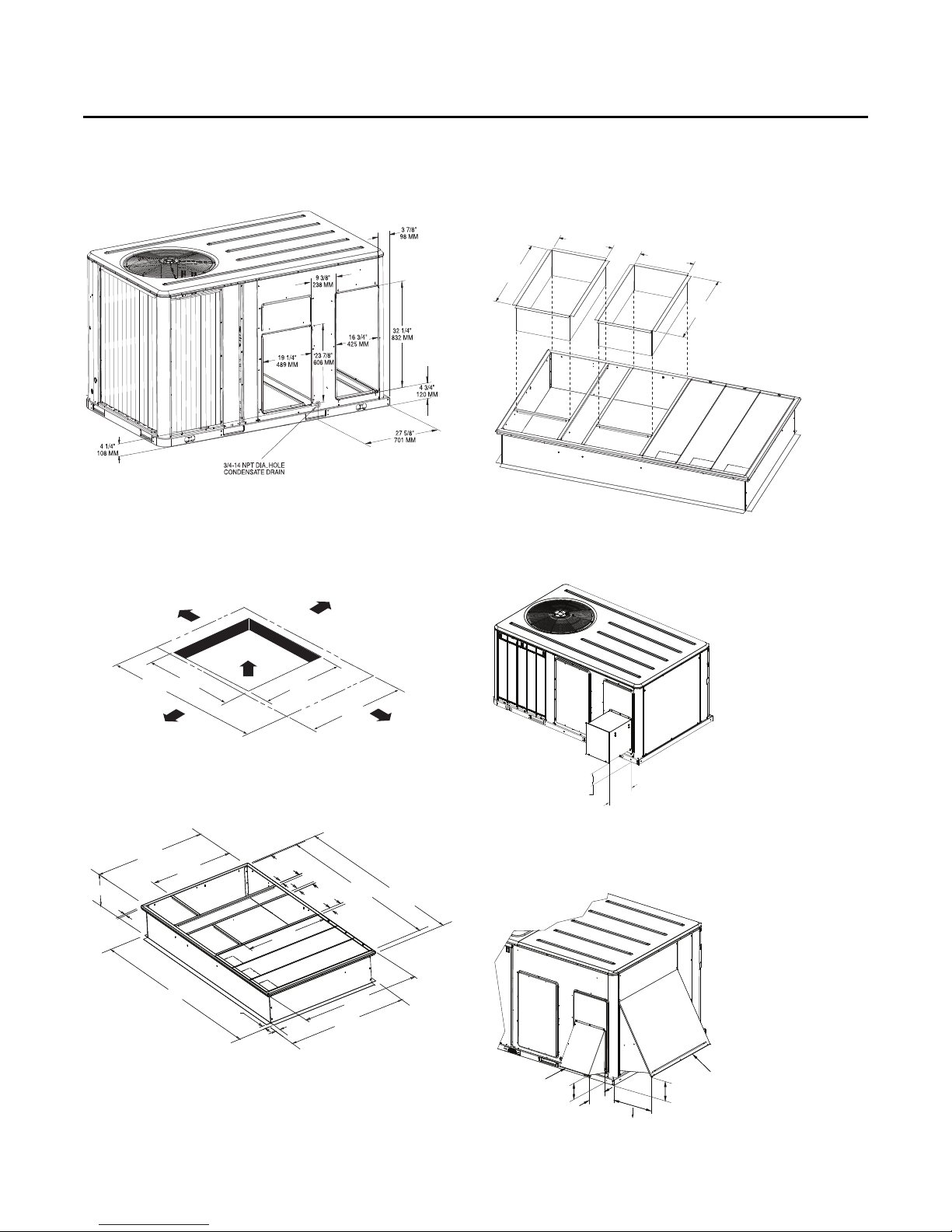
Figure 9. Heat pump - 3 to 4 tons standard efficiency, 3
ton high efficiency - economizer, manual or
motorized fresh air damper; power exhaust
16 1/4”
159 MM
6 3/16”
157 MM
12 1/2”
16 1/2”
318 MM
419 MM
Dimensions extends to 16 1/2"/419 MM
when powered exhaust is coupled
with low leak economizer
Figure 10. Heat pump 3 to 4 tons standard efficiency, 3
ton high efficiency - economizer & barometric
relief damper hood
Figure 11. Heat pump - 3 to 4 tons standard efficiency, 3
ton high efficiency - swing diameter for
hinged door(s) option
Figure 12. Heat pump - 5 to 10 tons standard efficiency, 4
to 5 ton high efficiency
Note: 2” electrical connection: single point power when heat installed
(WSC, W/DHC)
RT-SVX23M-EN 17
Figure 13. Heat pumps - 5 to 10 tons standard efficiency,
4 to 5 ton high efficiency - downflow airflow
supply/return - through-the-base utilities
Page 18
Dimensions and Weights
Supply
Return
CLEARANCE 36” (914 MM)
CLEARANCE FROM
TOP OF UNIT 72”
TYPICAL ROOF OPENING
CLEARANCE 48” (1219 MM)
CLEARANCE 36” (914 MM)
CLEARANCE
HORIZONTAL FLOW - 18” (457 MM)
DOWNFLOW - 36” (914 MM)
53 1/4”
1352 MM
46”
1168 MM
46”
1168 MM
88 5/8”
2251 MM
CLEARANCE 36” (914 MM)
CLEARANCE 36” (914 MM)
CLEARANCE 48” (1219 MM)
CLEARANCE 36” (914 MM) FOR DOWNFLOW
CLEARANCE 18” (457 MM) FOR HORIZONTAL
46 3/8”
1178 MM
1 3/4”
44 MM
46 3/8”
1178 MM
34 3/8”
873 MM
84 1/2”
2146 MM
2”
51 MM
34 3/8”
873 MM
1”
25 MM
49 7/8”
1267 MM
50 3/8”
1280 MM
2”
51 MM
83 7/8”
2130 MM
80 1/2”
2045 MM
18 1/2”
470 MM
1”
25 MM
6 5/8”
168 MM
18 1/4”
470 MM
1”
25 MM
RETURN
SUPPLY
BAROMETRIC RELIEF HOOD
ECONOMIZER HOOD
Dimensions extends to 21 5/8"/549 MM
when powered exhaust is coupled
with low leak economizer
7 3/4”
198 MM
12”
304 MM
16 3/4”
425 MM
6 7/8”
175 MM
Figure 14. Heat pumps - 5 to 10 tons standard efficiency,
4 to 5 ton high efficiency - horizontal airflow
supply and return
Figure 15. Heat pumps - 5 to 10 tons standard efficiency,
4 to 5 ton high efficiency - unit clearance and
roof opening
Figure 17. Heat pumps - 5 to 10 tons standard efficiency,
4 to 5 ton high efficiency - downflow duct
connections field fabricated
Note: Reference tabular information for duct clearance to combustible
materials in the Installation chapter.
17 3/4”
33 3/4”
857 MM
451MM
17 3/4”
451MM
33 3/4”
857 MM
ALL FLANGES 1 1/4" (31 MM)
RETURN
SUPPLY
Figure 18. Heat pumps - 5 to 10 tons standard efficiency,
4 to 5 ton high efficiency - power exhaust
Figure 16. Heat pumps - 5 to 10 tons standard efficiency,
4 to 5 ton high efficiency - roof curb
18 RT-SVX23M-EN
6 11/16”
16 1/2”
170 MM
419 MM
Figure 19. Heat pumps - 5 to 10 tons standard efficiency,
4 to 5 ton high efficiency - economizer, manual
or motorized fresh air damper
BAROMETRIC RELIEF HOOD
7 3/4”
198 MM
12”
16 3/4”
304 MM
425 MM
Dimensions extends to 21 5/8"/549 MM
when powered exhaust is coupled
with low leak economizer
6 7/8”
175 MM
ECONOMIZER HOOD
Page 19
Dimensions and Weights
21 3/8”
543 MM
17”
432 MM
34 5/8”
879 MM
Applicable to
Y_C/DHC models only
1/2 NPT GAS CONNECTION
(80 mbh, 120 mbh)
3/4 NPT GAS CONNECTION
(150 mbh, 200 mbh, 250 mbh)
(YC MODELS)
EVAPORATOR SECTION
ACCESS PANEL
ALTERNATE CONDENSATE DRAIN
CONNECTION 3/4 - 14 NPT DIA. HOLE
4 1/4”
108 MM
27 5/8”
701 MM
88 5/8”
2251 MM
47 7/8”
1216 MM
24 1/2”
622 MM
9 5/8”
244 MM
5 5/8”
143 MM
4 1/4”
108 MM
5 5/8”
143 MM
7 5/8”
194 MM
53 1/4”
1353 MM
CONDENSER COIL
UNIT CONTROL WIRE
7/8” (22 MM) DIA. HOLE
SERVICE GAUGE PORT ACCESS
1 3/8” (35 MM) DIA. HOLE
UNIT CONTROL WIRE
1 3/8” (35 MM) DIA. HOLE
46 7/8”
1190 MM
CONDENSER FAN
TOP PANEL
CONTROL AND COMPRESSOR
ACCESS PANEL
RETURNRETURN
SUPPLYSUPPLY
3 5/8”3 5/8”
92 MM92 MM
17 1/2”17 1/2”
444 MM444 MM
9 7/8”9 7/8”
251 MM251 MM
17 1/2”17 1/2”
444 MM444 MM
32 1/8”32 1/8”
816 MM816 MM
33”33”
838 MM838 MM
4”4”
102 MM102 MM
THROUGH THE THROUGH THE
BASE ELECTRICALBASE ELECTRICAL
THROUGH THE THROUGH THE
BASE CONDENSATEBASE CONDENSATE
4 5/8”4 5/8”
119 MM119 MM
THROUGH THETHROUGH THE
BASE GASBASE GAS
5 7/8”5 7/8”
149 MM149 MM
27 5/8”27 5/8”
701 MM701 MM
42 3/16”42 3/16”
1072 MM1072 MM
6 3/8”6 3/8”
163 MM163 MM
2 3/4”2 3/4”
71 MM71 MM
51 3/16”51 3/16”
1316 MM1316 MM
4 1/8”4 1/8”
104 MM104 MM
UNIT CONTROL WIRE
7/8” (22 MM) DIA. HOLE
CONTROL BOX SECTION
ACCESS PANEL
EVAPORATOR SECTION
ACCESS PANEL
ALTERNATE CONDENSATE DRAIN
CONNECTION 3/4 - 14 NPT DIA. HOLE
1/2 NPT GAS CONNECTION
(120 MBh)
3/4 NPT GAS CONNECTION
(150 MBh, 200 MBh, 250 MBh)
27 5/8”
701 MM
47 7/8”
1216 MM
99 11/16”
2532 MM
63 3/16”
1605 MM
50 7/8”
1292 MM
UNIT POWER WIRE
1 3/8” (35 MM) DIA. HOLE
SERVICE GAUGE
PORT ACCESS
1 3/8” (35 MM) DIA. HOLE
COMPRESSOR ACCESS PANEL
CONDENSER COIL
OUTDOOR TOP PANEL
INDOOR TOP PANEL
CLEARANCE 36” (914 MM)
CLEARANCE
HORIZONTAL FLOW - 18” (457 MM)
DOWNFLOW 36” (914 MM)
TYPICAL ROOF OPENING
CLEARANCE 36” (914 MM)
CLEARANCE 48” (1219 MM)
CLEARANCE FROM
TOP OF UNIT 72”
63 3/16”
1605 MM
46”
1168 MM
46”
1168 MM
99 11/16”
2532 MM
56 3/8”
1432 MM
14”
356 MM
1 3/4”
44 MM
34 3/8”
873 MM
18 1/2”
470 MM
1”
25 MM
6 5/8”
168 MM
1”
25 MM
18 1/2”
470 MM
1”
25 MM
80 1/2”
2045 MM
83 7/8”
2130 MM
CLEARANCE 36” (914 MM) FOR DOWNFLOW
CLEARANCE 18” (457 MM) FOR HORIZONTAL
34 3/8”
873 MM
59 7/8”
1521 MM
60 3/8”
1534 MM
2”
51 MM
2”
51 MM
84 1/2”
2146 MM
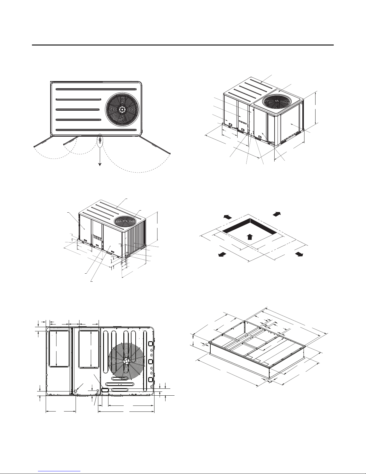
Figure 20. Heat pumps - 5 to 10 tons standard efficiency,
4 to 5 ton high efficiency - swing diameter for
hinged door(s) option
Figure 21. Heat pump - 7.5 to 10 tons standard efficiency
Figure 23. Heat pump - 10 tons high efficiency
Note: 2" Electrical Connection: Single Point Power When Heat Installed.
Figure 24. Heat pump - 10 tons high efficiency - unit
clearance and roof opening
Figure 22. Heat pump - 10 tons high efficiency -
downflow airflow supply/return through-thebase utilities
RT-SVX23M-EN 19
Figure 25. Heat pump - 10 tons high efficiency - roof curb
Note: 2" Electrical Connection: Single Point Power When Heat Installed
18 1/2”
470 MM
1”
25 MM
2”
51 MM
356 MM
56 3/8”
34 3/8”
1432 MM
873 MM
14”
1 3/4”
44 MM
84 1/2”
2146 MM
6 5/8”
168 MM
1”
25 MM
34 3/8”
873 MM
2”
51 MM
CLEARANCE 36” (914 MM) FOR DOWNFLOW
CLEARANCE 18” (457 MM) FOR HORIZONTAL
80 1/2”
18 1/2”
2045 MM
470 MM
1”
25 MM
59 7/8”
1521 MM
60 3/8”
1534 MM
83 7/8”
2130 MM
Page 20
Installation
SUPPLY
RETURN
3/4-14 NPT
DRAIN CONNECTION
CONDENSER COIL
17 1/4”
438 MM
8 7/8”
225 MM
13 1/4”
337 MM
23 1/4”
591 MM
3 3/16”
81 MM
14 3/4”
375 MM
4 3/4”
121 MM
Foundation
Horizontal Units
If the unit is installed at ground level, elevate it above the
snow line. Provide concrete footings at each support
location with a “full perimeter” support structure or a slab
foundation for support. For the unit’s operating and point
loading weights when constructing a footing foundation,
refer to the maximum unit/corner weights table in the
weights section of this manual.
If anchoring is required, anchor the unit to the slab using
hold down bolts or isolators. Isolators should be installed
to minimize the transmission of vibrations into the
building.
WARNING
Risk of Roof Collapsing!
Failure to ensure proper structural roof support could
cause the roof to collapse, which could result in death
or serious injury and property damage. Confirm with a
structural engineer that the roof structure is strong
enough to support the combined weight of the
roofcurb and the unit. Refer to the weights section for
typical unit and curb weights.
For rooftop applications, ensure the roof is strong enough
to support the combined unit and support structural
weight. If anchoring is required, anchor the unit to the roof
with hold-down bolts or isolators.
Check with a roofing contractor for proper waterproofing
procedures.
Ductwork
Supply and return air openings as viewed from the rear of
the unit are shown in the following drawings.
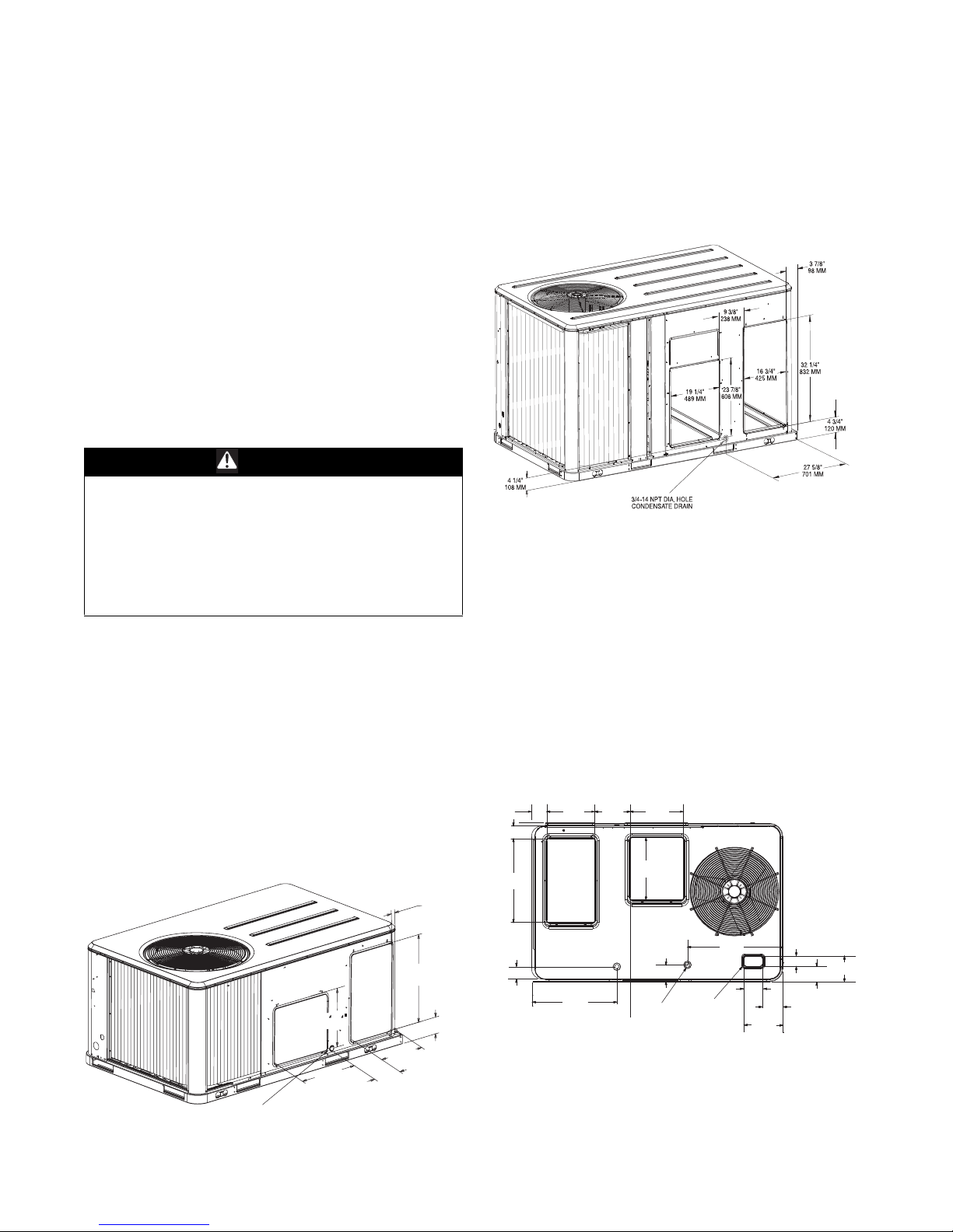
Figure 26. Heat pump - 3 to 4 tons standard efficiency, 3
ton high efficiency - horizontal airflow supply/
return
Figure 27. Heat pumps - 5 to 10 tons standard efficiency,
4 to 5 ton high efficiency - horizontal airflow
supply and return
Return
Supply
Supply and return air openings as viewed from a
downflow configuration to 5 are shown in the following
drawings.
Elbows with turning vanes or splitters are recommended
to minimize air noise due to turbulence and to reduce static
pressure.
When attaching the ductwork to the unit, provide a watertight flexible connector at the unit to prevent operating
sounds from transmitting through the ductwork.
All outdoor ductwork between the unit and the structure
should be weather proofed after installation is completed.
Figure 28. Heat pump - 3 to 4 tons standard efficiency, 3
ton high efficiency - downflow airflow supply/
return - through-the-base utilities
3 5/8”
92 MM
102 MM
610 MM
24”
4”
RETURN
14”
356 MM
9 1/4”
235 MM
15 1/2”
394 MM
18”
457 MM
SUPPLY
20 RT-SVX23M-EN
4 3/16”
106 MM
TBU CONDENSATE
23 1/2”
597 MM
4 9/16”
116 MM
THROUGH
THE BASE GAS
(Y_C/DHC MODELS ONLY)
ELECTRICAL
27 9/16”
701 MM
THROUGH
THE BASE
4 7/8”
124 MM
9 15/16”
253 MM
5 1/16”
128 MM
2 13/16”
71 MM
3 11/16”
94 MM
6 1/2”
165 MM
Page 21
Installation
3 5/8”
92 MM
17 1/2”
444 MM
4”
102 MM
9 7/8”
251 MM
17 1/2”
444 MM
32 1/8”
816 MM
RETURN
SUPPLY
33”
838 MM
4 1/8”
104 MM
27 5/8”
701 MM
THROUGH THE
BASE CONDENSATE
40 3/4”
1035 MM
THROUGH THE
BASE ELECTRICAL
5 7/8”
149 MM
5”
127 MM
10 7/8”
276 MM
3 3/4”
95 MM
2 3/4”
71 MM
6 1/2”
165 MM
RETURNRETURN
SUPPLYSUPPLY
3 5/8”3 5/8”
92 MM92 MM
17 1/2”17 1/2”
444 MM444 MM
9 7/8”9 7/8”
251 MM251 MM
17 1/2”17 1/2”
444 MM444 MM
32 1/8”32 1/8”
816 MM816 MM
33”33”
838 MM838 MM
4”4”
102 MM102 MM
THROUGH THE THROUGH THE
BASE ELECTRICALBASE ELECTRICAL
THROUGH THE THROUGH THE
BASE CONDENSATEBASE CONDENSATE
4 5/8”4 5/8”
119 MM119 MM
THROUGH THETHROUGH THE
BASE GASBASE GAS
5 7/8”5 7/8”
149 MM149 MM
27 5/8”27 5/8”
701 MM701 MM
42 3/16”42 3/16”
1072 MM1072 MM
6 3/8”6 3/8”
163 MM163 MM
2 3/4”2 3/4”
71 MM71 MM
51 3/16”51 3/16”
1316 MM1316 MM
4 1/8”4 1/8”
104 MM104 MM
Base Alignment Bracket
Figure 29. Heat pumps - 5 to 10 tons standard efficiency,
4 to 5 ton high efficiency - downflow airflow
supply/return - through-the-base utilities
Figure 30. Heat pump - 10 tons high efficiency -
downflow airflow supply/return through-thebase utilities
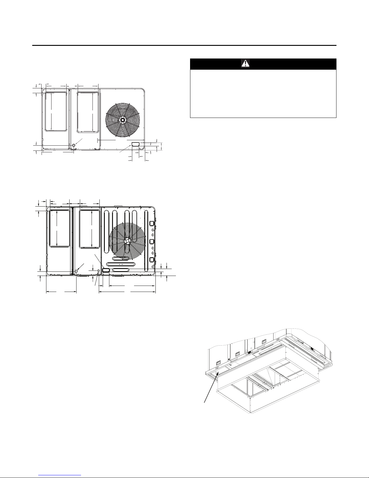
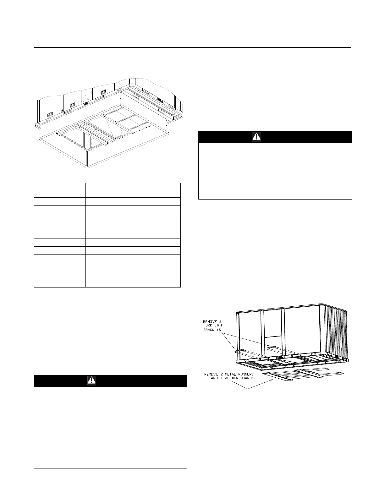
Roof Curb
The roof curbs for these units consists of a "full perimeter"
enclosure to support the unit just inside of the unit base
rail. The WSC120E, W/DHC120H unit contains a support
base alignment rail and will extend past the end of the roof
curb as shown in figures below.
Before installing any roof curb, verify;
• It is the correct curb for the unit,
• The necessary gaskets and hardware are included,
• The purposed installation location provides the
required clearance for proper operation.
• Insure that the curb is level and square. The top surface
RT-SVX23M-EN 21
of the curb must be true to assure an adequate curb-tounit seal.
WARNING
Combustible Materials!
Failure to maintain proper clearance between the unit
heat exchanger, vent surfaces and combustible
materials could cause a fire which could result in death
or serious injury or property damage. Refer to unit
nameplate and installation instructions for proper
clearances.
Verify that appropriate materials were used in the
construction of roof and ductwork. Combustible materials
should not be used in the construction of ductwork or roof
curb that is in close proximity to heater elements or any
hot surface. Any combustible material on the inside of the
unit base should be removed and replaced with
appropriate material.
Step-by-step curb assembly and installation instructions
ship with each accessory roof curb kit. Follow the
instructions carefully to assure proper fit-up when the unit
is set into place.
Note: To assure proper condensate flow during
operation, as well as proper operation of the
condensate overflow switch (if equipped), the unit
and curb must be level.
If the unit is elevated, a field constructed catwalk around
the unit is strongly recommended to provide easy access
for unit maintenance and service.
Recommendations for installing the Supply Air and Return
Air ductwork joining the roof curb are included in the curb
instruction booklet. Curb ductwork must be fabricated and
installed by the installing contractor before the unit is set
into place.
Note: For sound consideration, cut only the holes in the
roof deck for the ductwork penetrations. Do not cut
out the entire roof deck within the curb perimeter.
Figure 31. View for base to roof curb alignment
WSC120E, W/DHC120H on 50 x 84 roof curb
Page 22
Installation
Figure 32. View for base to roof curb alignment
WSC120E, W/DHC120H on 60 x 84 roof curb
Model Number
WSC036H 0
WSC048H 0
WSC060H 0
WSC072E/H 1
WSC090E/H 1
WSC092H 1
WSC102H 1
WSC120E/H 1
WHC036H 0
WHC048H 0
WHC060H 0
Clearance required from duct to
combustible surfaces (inches)
If a Curb Accessory Kit is not used:
• The ductwork can be attached directly to the factoryprovided flanges around the unit’s supply and return
air openings. Be sure to use flexible duct connections
at the unit.
• For “built-up” curbs supplied by others, gaskets must
be installed around the curb perimeter flange and the
supply and return air opening flanges.
A Rigging illustration and Center-of-Gravity dimensional
data table is shown in the weights section. Refer to the
typical unit operating weights table before proceeding.
1. Remove all drill screws fastening wood protection to
metal baserail. Remove all screws securing wooden
protection to wooden top crate.
On 7.5-10 ton high efficiency units, remove wire ties
from outdoor grill.
2. Remove wooden top crate.
WARNING
Improper Unit Lift!
Failure to properly lift unit could result in unit dropping
and possibly crushing operator/technician which could
result in death or serious injury, and equipment or
property-only damage. Test lift unit approximately 24
inches to verify proper center of gravity lift point. To
avoid dropping of unit, reposition lifting point if unit is
not level.
3. Rig the unit as shown in the weights section. Attach
adequate strength lifting slings to all four lifting
brackets in the unit base rail. Do not use cables, chains,
or slings except as shown.
4. Install a lifting bar, as shown in the weights section to
protect the unit and to facilitate a uniform lift. The
minimum distance between the lifting hook and the
top of the unit should be 7 feet.
5. Test-lift the unit to ensure it is properly rigged and
balanced, make any necessary rigging adjustments.
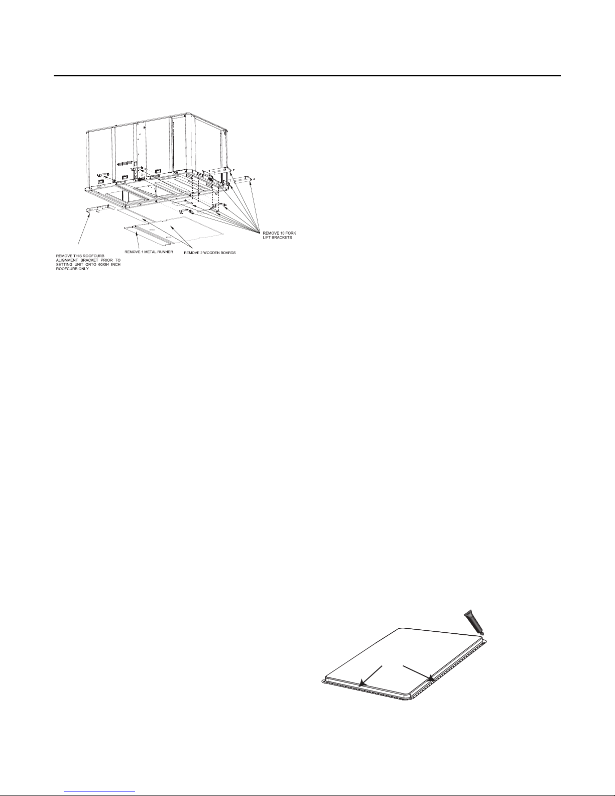
Figure 33. Fork lift pockets (all heat pump units except
W/DHC120H)
Rigging
WARN ING
Heavy Objects!
Failure to follow instructions below or properly lift unit
could result in unit dropping and possibly crushing
operator/technician which could result in death or
serious injury, and equipment or property-only damage.
Ensure that all the lifting equipment used is properly
rated for the weight of the unit being lifted. Each of the
cables (chains or slings), hooks, and shackles used to
lift the unit must be capable of supporting the entire
weight of the unit. Lifting cables (chains or slings) may
not be of the same length. Adjust as necessary for even
unit lift.
22 RT-SVX23M-EN
Page 23
Installation
Figure 34. Fork lift pockets (W/DHC120H)
NOTICE
6. Lift the unit enough to allow the removal of base fork
pocket protection components as shown in the
following figures.
7. When 10 ton units are installed on smaller existing roof
curb (50"x 84") for replacement applications, do not
remove alignment bracket. This bracket helps assure
proper alignment of duct openings.
8. Downflow units; align the base rail of the unit with the
curb rail while lowering the unit onto the curb. Make
sure that the gasket on the curb is not damaged while
positioning the unit.
General Unit Requirements
The checklist listed below is a summary of the steps
required to successfully install a commercial unit. This
checklist is intended to acquaint the installing personnel
with what is required in the installation process. It does not
replace the detailed instructions called out in the
applicable sections of this manual.
• Check the unit for shipping damage and material
shortage; file a freight claim and notify appropriate
sales representative.
• Verify correct model, options and voltage from unit
nameplate.
• Verify that the installation location of the unit will
provide the required clearance for proper operation.
• Assemble and install the roof curb (if applicable). Refer
to the latest edition of the curb installers guide that
ships with each curb kit.
• Fabricate and install ductwork; secure ductwork to
curb.
• Rig the unit.
• Set the unit onto the curb; check for levelness.
• Ensure unit-to-curb seal is tight and without buckles or
cracks.
• Install and connect a condensate drain line to the
evaporator drain connection.
Note: Condensate Overflow Switch (if equipped) will not
work if unit is not level or slightly sloped toward
switch.
Factory Installed Economizer
• Ensure the economizer has been pulled out into the
operating position. Refer to the economizer installers
guide for proper position and setup.
• Install all access panels.
Temperature Limit Switch Usage for
Electric Heat Units
Units are factory shipped in the downflow discharge
configuration but can be field converted to a horizontal
discharge configuration. Some, but not all units require a
different TCO-A limit switch, which is wire tied near the
terminal block in the heater compartment if horizontal
discharge configuration is used. See Figure 40, p. 25 for
the location of TCO-A.
Horizontal Discharge Conversion
WSC036H, WSC048H,
W/DHC036H
Note: 3 to 4 ton standard efficiency and 3 ton high
efficiency units supply cover to supply opening and
return cover to return opening.
• Supplies Needed by Installer for Conversion: 3 oz. tube
of High Temperature RTV sealant. (500°F/260°C:
Similar to Dow Corning 736)
Important: Failure to use recommended sealant could
result in unit performance loss.
If a unit is to be converted to a horizontal discharge, the
following conversion must be performed:
1. Remove RETURN and SUPPLY duct covers.
2. Locate supply cover. Apply ¼ in. (6mm.) continuous
bead of 500°F RTV sealant to the flange as shown in the
following drawing.
Figure 35. Supply duct cover
RTV Sealant
3. Position SUPPLY DUCT COVER as shown, rotate 90
degrees to allow entrance into supply opening.
RT-SVX23M-EN 23
Page 24
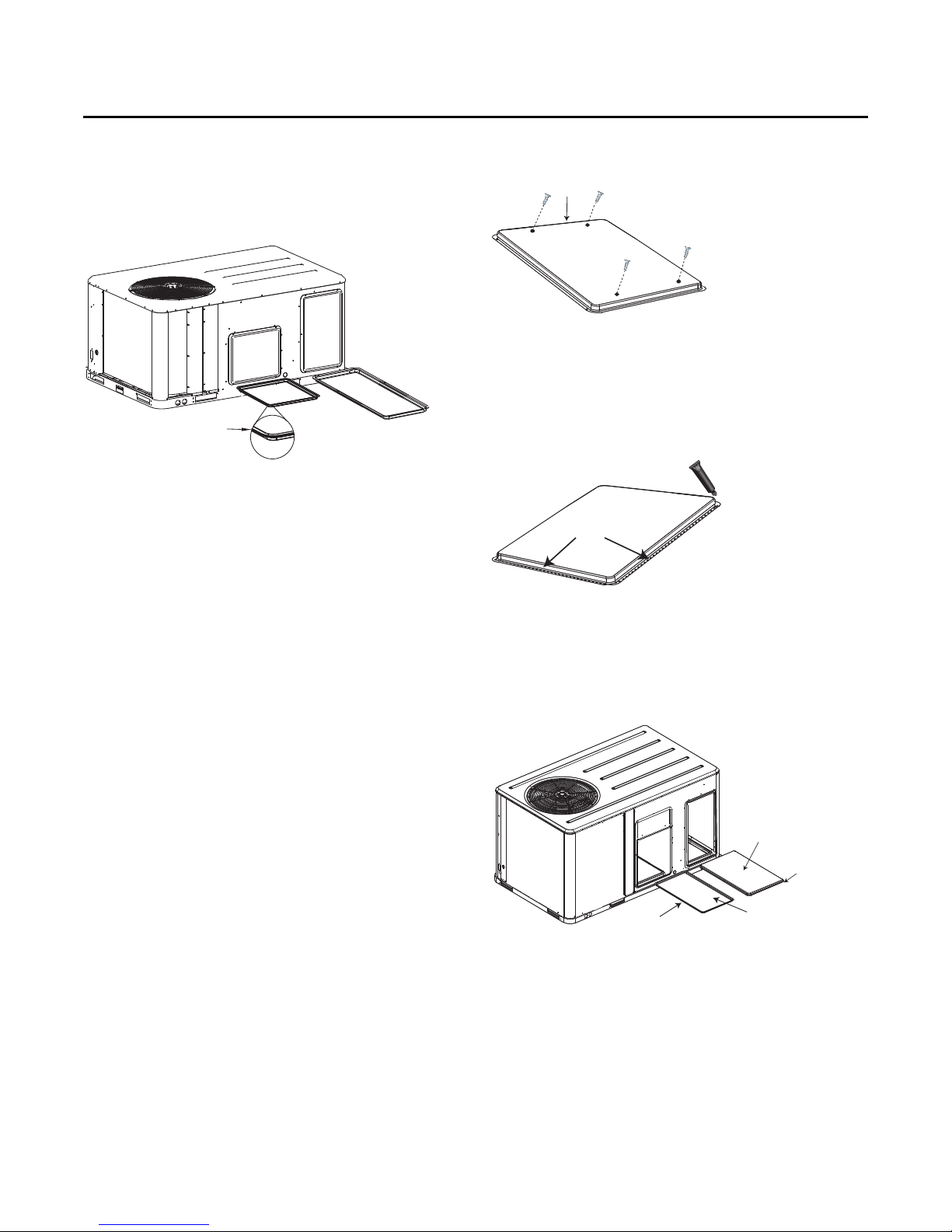
Installation
Supply duct cover with
RTV installed
RTV Sealant
4. Slide SUPPLY DUCT COVER into duct openings until
inward edge of duct cover engages with the 2 retaining
clips on the duct flanges. Secure the outward edge of
each duct cover with 2 screws.
Figure 36. Supply & return openings
5. Slide RETURN DUCT COVER (insulation side up) into
supply opening until inward edge of duct cover
engages with the 2 retaining clips on the duct flange.
Secure out-ward edge of the duct cover with two
screws.
Note: Certain unit/electric heater combinations require a
limit switch change out for horizontal airflow
applications. Refer to the following instructions to
determine if this process is required for the unit
undergoing installation.
6. After completing installation of the duct covers for
horizontal discharge, proceed to TCO-1 instructions.
Figure 37. Supply duct cover
Supply Duct Cover
Screw into 4
dimples on top
edge
4. On original RETURN DUCT COVER, apply ¼” (6mm.)
continuous bead of 500°F RTV sealant around flange
(opposite insulation side), as shown.
Figure 38. Return duct cover
5. Slide RETURN DUCT COVER (insulation side up) into
supply opening until inward edge of duct cover
engages with the 2 retaining clips on the duct flange.
Secure outward edge of the duct cover with two
screws.
Horizontal Discharge Conversion
WSC060H-120E/H, W/DHC048120H
Note: 5 to 10 ton standard efficiency units and 4 to 10 ton
high efficiency supply cover to return opening and
return cover to supply opening.
• Supplies needed by installer for conversion: 3 oz. tube
of high Temperature RTV sealant. (500°F/260°C:
Similar to Dow Corning 736)
Important: Failure to use recommended sealant could
result in unit performance loss.
If a unit is to be converted to a Horizontal discharge, the
following conversion must be performed:
1. Remove RETURN and SUPPLY duct covers.
2. Place SUPPLY DUCT COVER over downflow return
opening. (insulation side down)
3. Using self-drilling screws, (or screws removed from
duct cover), screw through dimples to attach Duct
Cover to base.
Figure 39. Supply & return openings
Supply duct cover
Insulation side
down
Insulation side up
Note: If unit is equipped with Return Air Smoke Detector,
refer to field conversion instructions for horizontal
discharge before installing return air duct.
Note: Certain unit/electric heater combinations require a
limit switch change out for horizontal airflow
applications. Refer to the following instructions to
determine if this process is required for the unit
undergoing installation.
6. After completing installation of the duct covers for
horizontal discharge, proceed to TCO-A instructions.
Return duct
cover
24 RT-SVX23M-EN
Page 25
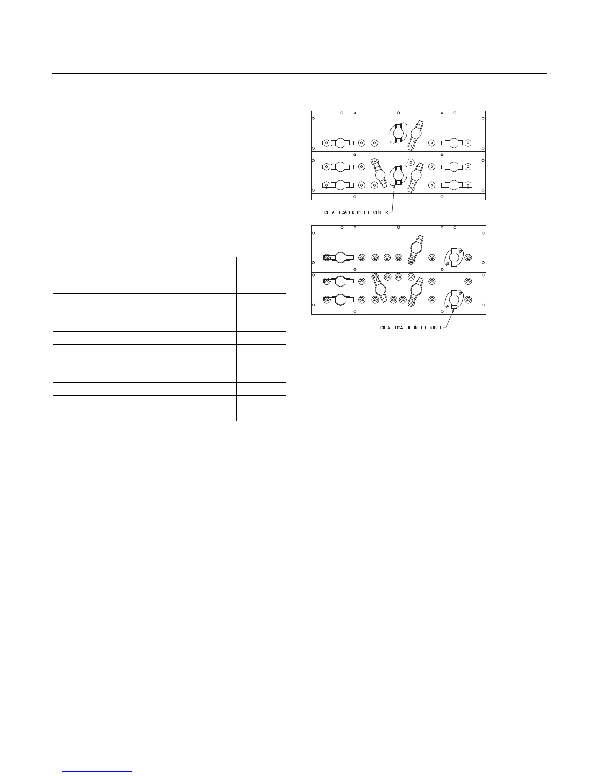
Installation
TCO-A Instructions
If the unit being installed is listed in the following table and
is equipped with the corresponding model number of
factory installed electric heater package in the table, the
limit control TCO-A must be replaced with the extra limit
control shipped in the heater compartment. Replace TCOA following the instructions in steps 1 through 3 below. If
the unit being installed does not have a factory installed
electric heater package or is equipped with a factory
installed electric heater model that does not correspond to
any in this table, skip steps 1 through 3 and go on to next
step in the installation process.
Table 3. TCO-A replaced for horizontal duct
Unit Model Number
WSC090H3, WSC092H3 BAYHTRU336 Center
WSC090H4, WSC092H4 BAYHTRU436 Center
1. Remove the heater section access panel and open the
electric heater dead front panel.
2. TCO-A is the limit control located in the central or right
part of the heater mounting plate and that is located on
the bottom of the two heater element assemblies. To
replace this device, first remove the two wires
connected to the terminals. Next, remove the two
screws which secure it to the heater element mounting
plate. Once TCO-A has been removed from the heater
element mounting plate, discard this device.
configuration
Electric Heater Model
Number
WSC102H3 BAYHTRU336 Center
WSC102H4 BAYHTRU436 Center
WSC120H4 BAYHTRA454 Right
WSC120EW BAYHTRBW36, W54 Right
WSC090E4 BAYHTRU427, 436 Center
WSC090EW BAYHTRUW27, W36 Center
WSC072H3 BAYHTRW327, 336 Center
WSC072H4 BAYHTRW427, 436 Center
WSC072HW BAYHTRWW27, W36 Center
TCO-A
location
Figure 40. TCO-A location
3. Obtain the replacement TCO-A which is secured by a
wire tie near the electric heater terminal block in the
heater compartment. Attach it to the heater element
mounting plate with the two screws that were removed
in step 2 above. Connect the two wires that were unhooked in step 2 to the terminals on the new TCO-A.
Refer to the heater package wiring diagram to assure
that the wiring is connected properly.
4. Close the electric heater dead front panel and replace
heat section access panel.
Return Air Smoke Detector
The factory installed Return Air Smoke Detector is
installed in the downflow discharge position. No
additional field setup is required.
If a unit is to be converted to Horizontal discharge, the
following conversion must be performed:
1. If the unit has an economizer, it must be pulled out in
the operating position.
2. Remove the 3 screws from the mounting brackets.
Refer to downflow view for screw locations.
Note: Refer to downflow view for screw locations.
RT-SVX23M-EN 25
Page 26
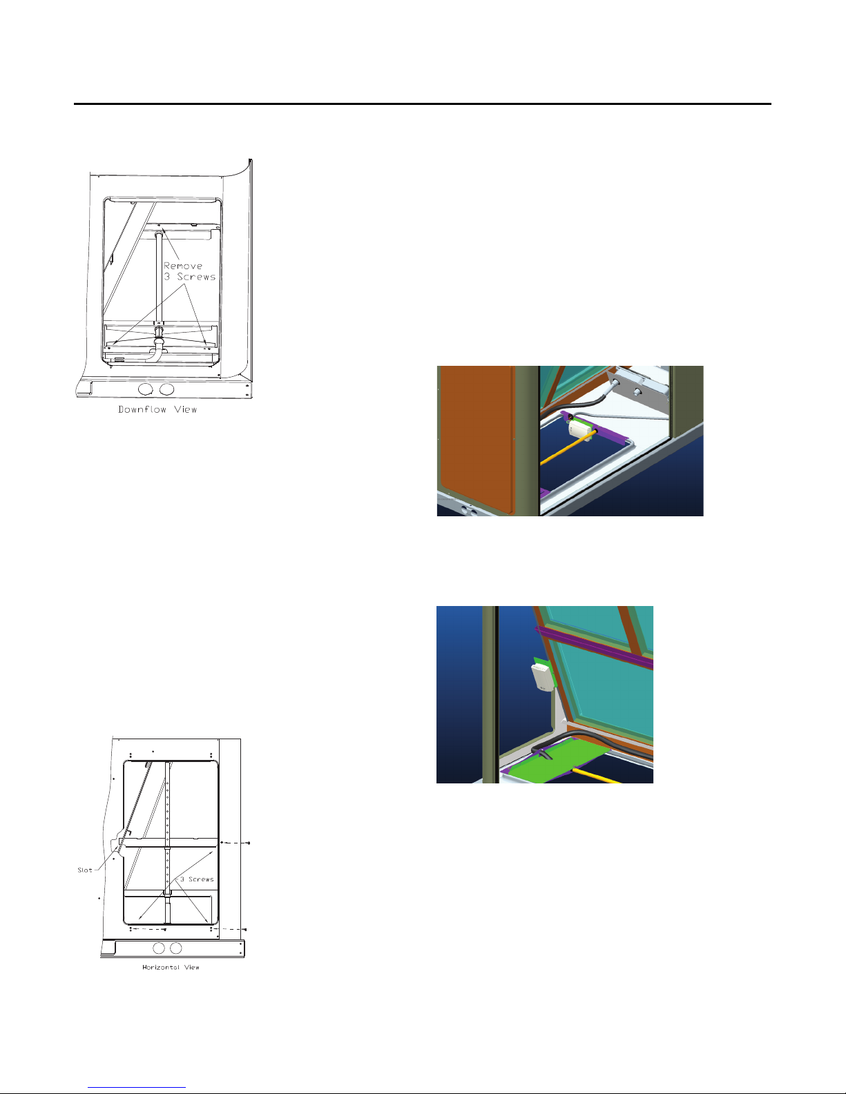
Installation
Figure 41. Downflow view
3. Lift the tube and bracket from the downflow duct
opening. Rotate the tube and bracket assembly 180°
degrees ensuring that the holes on the copper sensing
tube face away from the unit and face the return air
ductwork.
Note: Refer to horizontal views below.
Note: Check to insure that the flexible tubing lies flat on
the base pan surface.
4. Slide the top bracket down the copper sensing tube,
insert the tab on the left side into the slot on the indoor
coil block off and secure the right side of the bracket
with one of the 3 screws removed in step 2.
Note: Refer to horizontal view.
5. Using the remaining 2 screws removed in step 2,
secure the bottom bracket.
Note: Refer to horizontal view below.
Air-Fi™ Wireless Communication
Interface
The factory installed wireless communications interface is
installed in the downflow discharge position.
If a unit is to be converted to horizontal discharge, the
following conversion must be performed:
1. If the unit has an economizer, it must be pulled out in
the operating position.
2. Remove the screw from the mounting bracket. Refer to
downflow view for screw and bracket location.
Figure 43. Wireless communication interface -
downflow
3. Mount the bracket in the horizontal discharge location.
Refer to horizontal view for screw and bracket location.
Figure 44. Wireless communication interface -
horizontal
Figure 42. Horizontal view
26 RT-SVX23M-EN
Note: Cable ties must be removed to allow the cable to
extend to the horizontal mounting location.
Page 27
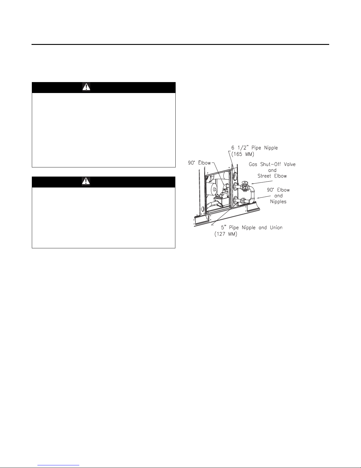
Installation
Main Electrical Power
Requirements
WARNING
Hazardous Voltage w/Capacitors!
Failure to disconnect power and discharge capacitors
before servicing could result in death or serious injury.
Disconnect all electric power, including remote
disconnects and discharge all motor start/run
capacitors before servicing. Follow proper lockout/
tagout procedures to ensure the power cannot be
inadvertently energized. Verify with an appropriate
voltmeter that all capacitors have discharged.
For additional information regarding the safe discharge
of capacitors, see PROD-SVB06A-EN
WARN ING
Proper Field Wiring and Grounding
Required!
Failure to follow code could result in death or serious
injury. All field wiring MUST be performed by qualified
personnel. Improperly installed and grounded field
wiring poses FIRE and ELECTROCUTION hazards. To
avoid these hazards, you MUST follow requirements for
field wiring installation and grounding as described in
NEC and your local/state electrical codes.
• Verify that the power supply complies with the unit
nameplate specifications.
• Inspect all control panel components; tighten any
loose connections.
• Connect properly sized and protected power supply
wiring to a field-supplied/installed disconnect switch
and to the main power terminal block (HTB1) in the unit
control panel.
• Install proper grounding wires to an earth ground.
Note: All field-installed wiring must comply with NEC
and applicable local codes.
Through-the-Base Gas
Installation
The gas supply line must extend 4?” above the base pan.
The “Through-the-Base Gas” kit is located in the heat
vestibule compartment. To gain access to the kit, remove
the Heat Compartment access panel.
1. Remove the pipe assembly strapped to the manifold.
Unscrew 90° elbow from 6½” nipple and slide rubber
grommet off of nipple.
2. Remove the plastic plug from the hole in the center
post and insert the grommet removed from
6½” pipe nipple.
3. Using pipe sealant, attach the 90° elbow to the gas
supply line.
4. Disconnect the 5" pipe nipple and union from the
“Through-the-Base Gas” kit assembly.
5. Using pipe sealant, attach the 6½” nipple and gas
shutoff assembly to the 90° elbow on the gas supply
line.
6. Using pipe sealant, attach the 5" pipe nipple and union
to the street el attached to the gas valve.
7. Connect 5" pipe nipple and union to 6½” nipple and
gas shutoff assembly.
Figure 45. Typical through-the-base gas installation
Requirements for Gas Heat
Note: The unit gas train and optional through-the-base
gas shut-off valve are rated at 1/2 PSIG maximum.
A pressure reducing regulator is recommended to
prevent this maximum from being exceeded.
These components must be isolated during field
gas piping test that exceed 1/2 PSIG. It is
recommended that the field piping be capped prior
to the unit gas train or optional through-the-base
gas shut-off valve if present.
• Gas supply line properly sized and connected to the
unit gas train.
• All gas piping joints properly sealed.
• Gas piping leak checked with a soap solution. If piping
connections to the unit are complete, do not pressurize
piping in excess of 0.50 psig or 14" W.C. to prevent
component failure.
• Drip leg Installed in the gas piping near the unit.
• Minimum gas supply pressure should be 4.5" W.C.
• Maximum gas supply pressure must not exceed 14.0"
W.C.
• Manifold pressure for single stage heaters should be
set to 3.3" W.C.
• Manifold pressure for two stage heaters should be set
to 3.5" W.C. on HIGH FIRE and 1.8" W.C. on LOW FIRE.
• Flue Exhaust clear of any obstruction.
RT-SVX23M-EN 27
Page 28
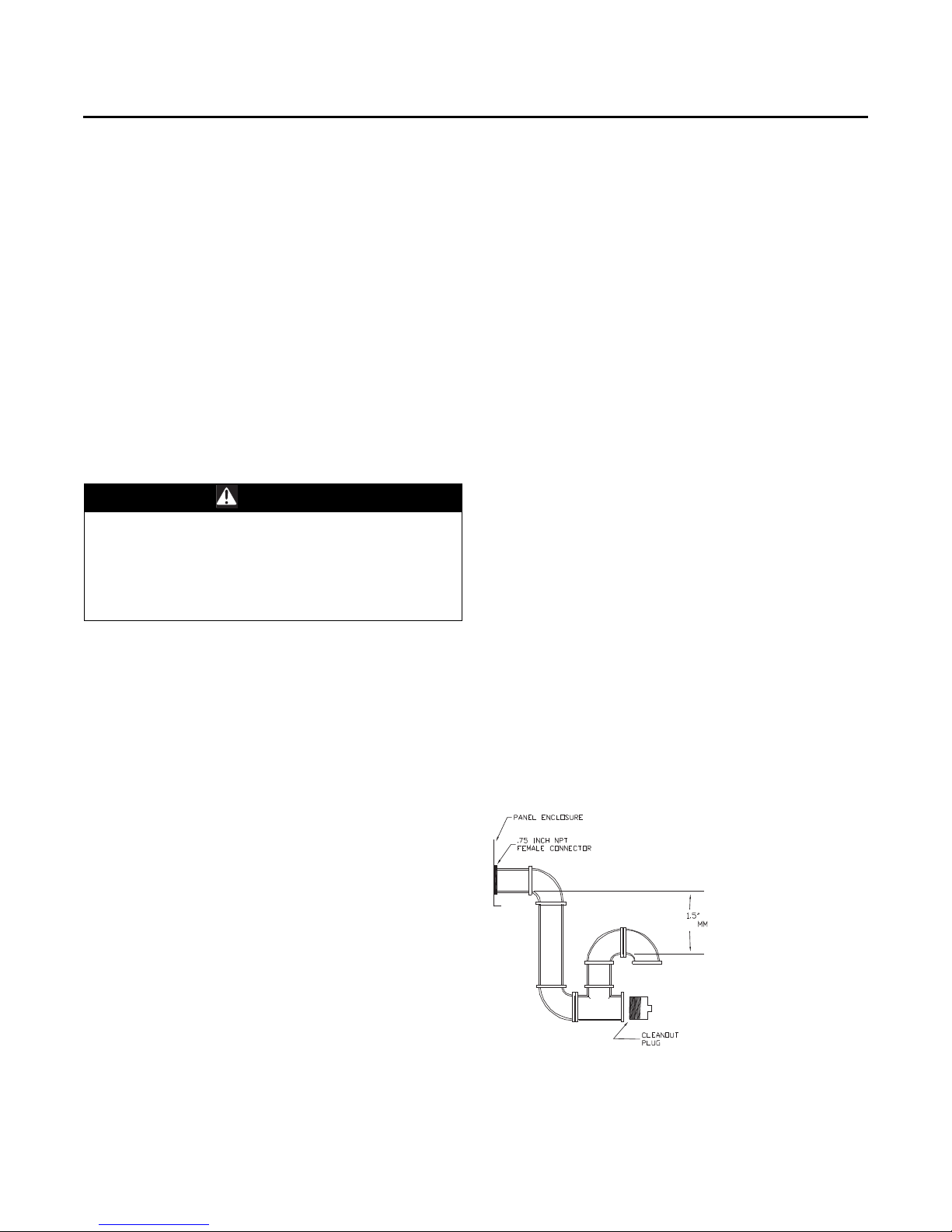
Installation
Electric Heat Requirements
• Verify that the power supply complies with the electric
heater specifications on the unit and heater nameplate.
• Inspect the heater junction box and control panel;
tighten any loose connections.
• Check electric heat circuits for continuity.
Low Voltage Wiring
(AC & DC) Requirements
• Install the zone thermostat, with or without switching
subbase.
• Connect properly sized control wiring to the proper
termination points between the zone thermostat and
the unit control panel.
Condensate Drain Configuration
WARN ING
Hazardous Voltage!
Failure to disconnect power before servicing could
result in death or serious injury. Disconnect all electric
power, including remote disconnects before servicing.
Follow proper lockout/tagout procedures to ensure the
power can not be inadvertently energized.
An evaporator condensate drain connection is provided
on each unit. Figure 26, p. 20 - Figure 30, p. 21 for the
appropriate drain location.
The condensate drain pan is factory installed to drain
condensate to the back side of the unit. See Figure 26, p. 20
- Figure 30, p. 21. It can be converted to drain condensate
out the front side of the unit or through the base.
To convert drain condensate out the front of
unit:
1. Remove evaporator access panel and supply air access
panels.
2. Remove the support panel that the condensate drain
pan exits through.
3. Slide the condensate drain pan out of the unit and
rotate 180°.
4. Slide the condensate drain pan back into the unit, align
the drain with the grommeted opening in the rear
support panel and push until the coupling is seated in
the grommet.
5. Replace the front support panel by aligning the panel
with tabs in the raceway. Align the condensate drain
pan support in the grommeted hole as the panel is put
in place.
6. Replace evaporator access panel and supply air access
panels.
To convert drain condensate through-the-base
of unit:
1. Remove evaporator access panel and supply air access
panels.
2. Remove the support panel that the condensate drain
pan exits through.
3. Slide the condensate drain pan out of the unit.
4. Place on a level surface in the position it was removed
from the unit.
5. Remove the plug knockout in the bottom of the drain
pan to convert it to through the base drainage.
6. Plug the original condensate drain opening with a field
supplied 3/4” NPT plug.
7. Slide the condensate drain pan back into the unit, align
the drain support with the grommeted opening in the
rear support panel and push until the support is seated
in the grommet.
8. Replace the front support panel by aligning the panel
with tabs in the raceway. Align the plugged condensate
drain pan coupling in the grommeted hole as the panel
is put in place.
9. Replace evaporator access panel and supply air access
panels.
A condensate trap must be installed at the unit due to the
drain connection being on the “negative pressure” side of
the fan. Install the P-Trap using the guidelines in Figure 46,
p. 28.
A condensate drain line must be connected to the P-Trap.
Pitch the drain lines at least 1/2 inch for every 10 feet of
horizontal run to assure proper condensate flow. Do not
allow the horizontal run to sag causing a possible doubletrap condition which could result in condensate backup
due to “air lock”.
Figure 46. Condensate trap installation
38.1
Drain Pan Removal (Units with Condensate
Overflow Switch Option)
Before drain pan removal, the switch wire must be
disconnected from wire tie on panel and/or any tape
before drain pan can be removed.
28 RT-SVX23M-EN
Page 29
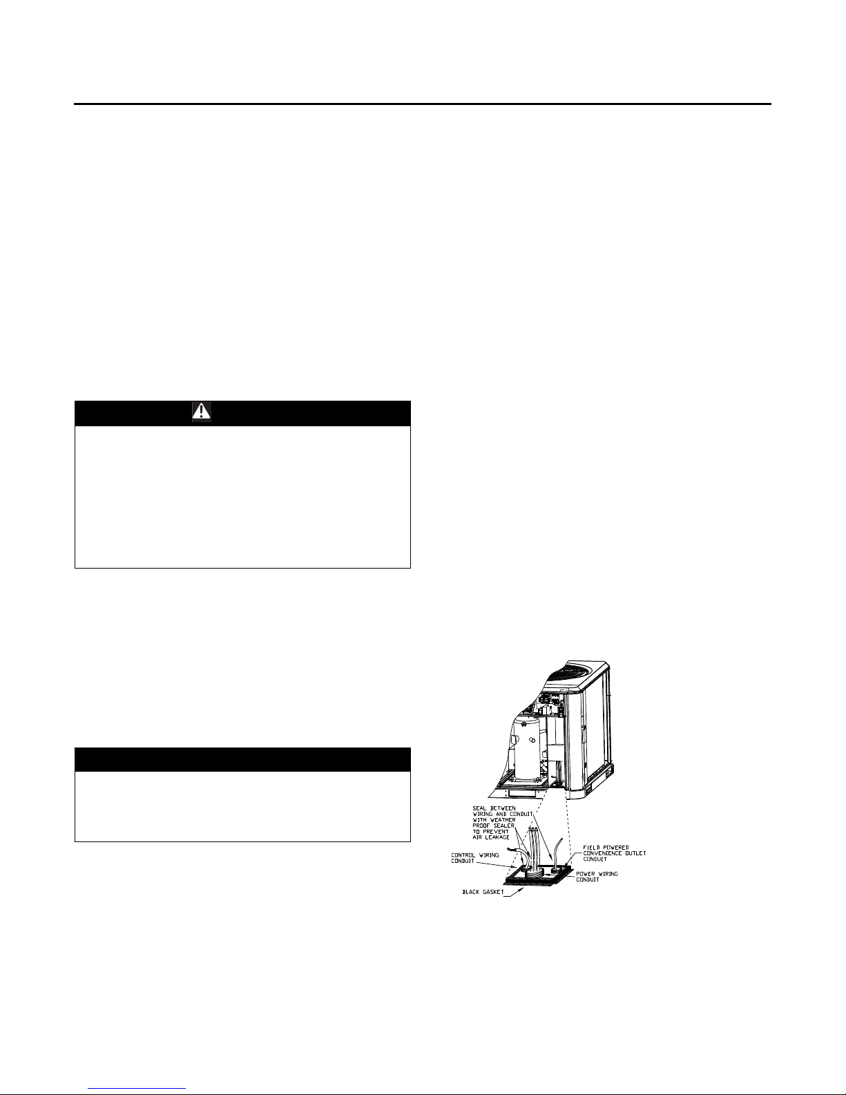
Installation
Care must be taken so the wire does not catch on the
bottom of indoor coil or any protrusion.
Note: When reversing the drain pan, on some units, the
condensate overflow switch will need to be moved
to the second hole in its bracket to avoid contact
with headers or indoor coil.
Filter Installation
The quantity of filters is determined by unit size. Access to
the filters is obtained by removing the filter access panel.
Refer to the unit Service Facts (shipped with each unit) for
filter requirements.
Note: Do not operate the unit without filters.
Field Installed Power Wiring
WARN ING
Proper Field Wiring and Grounding
Required!
Failure to follow code could result in death or serious
injury. All field wiring MUST be performed by qualified
personnel. Improperly installed and grounded field
wiring poses FIRE and ELECTROCUTION hazards. To
avoid these hazards, you MUST follow requirements for
field wiring installation and grounding as described in
NEC and your local/state electrical codes.
An overall dimensional layout for the field installed wiring
entrance into the unit is illustrated in the Dimensions and
Weights chapter. To insure that the unit’s supply power
wiring is properly sized and installed, follow the guidelines
outlined below.
Verify that the power supply available is compatible with
the unit’s nameplate ratings. The available supply power
must be within 10% of the rated voltage stamped on the
nameplate. Use only copper conductors to connect the
power supply to the unit.
otherwise, connect at the Compressor Contactor
(CC1). Refer to the customer connection diagram that
is shipped with the unit for specific termination points.
2. Provide proper grounding for the unit in accordance
with local and national codes.
Optional TBUE Wiring (Through-the-Base
Electrical Option)
1. Location of the applicable electrical service is
illustrated below. Refer to the customer connection
diagram that is shipped with the unit for specific
termination points. The termination points, depending
on the customer option selected would be a factory
mounted non-fused disconnect switch (UDC) or circuit
breaker (UCB). If neither a factory mounted non-fused
disconnect switch (UDC) or circuit breaker (UCB) was
factory mounted, field wiring connections should be
terminated in the control box at Compressor Contactor
# 1 (CC1).
2. Provide proper grounding for the unit in accordance
with local and national codes.
Note: Black Gasket is shipped from the factory and is
located in the literature ship with bag in the control
box. Apply Black Gasket around conduit plate on all
4 sides after installation to prevent air leakage from
the building entering the electrical enclosures.
Note: Seal between wiring and conduit with Black Gasket
or weather proof sealer to prevent air leakage from
the building entering the electrical enclosures. Also
seal around conduit and wiring at all roof and curb
penetrations.
Figure 47. All units except WSC120E, W/DHC120H
NOTICE:
Use Copper Conductors Only!
Failure to use copper conductors could result in
equipment damage as unit terminals are not designed
to accept other types of conductors.
Note: If the unit is not equipped with an optional factory
installed non-fused disconnect switch or circuit
breaker, a field supplied disconnect switch must be
installed at or near the unit in accordance with the
National Electrical Code (NEC latest edition).
Standard Wiring
1. Location of the applicable electrical service entrance is
illustrated in the Dimensions and Weights chapter.
Complete the unit's power wiring connections at the
main power terminal block (HTB1) if equipped;
RT-SVX23M-EN 29
Page 30
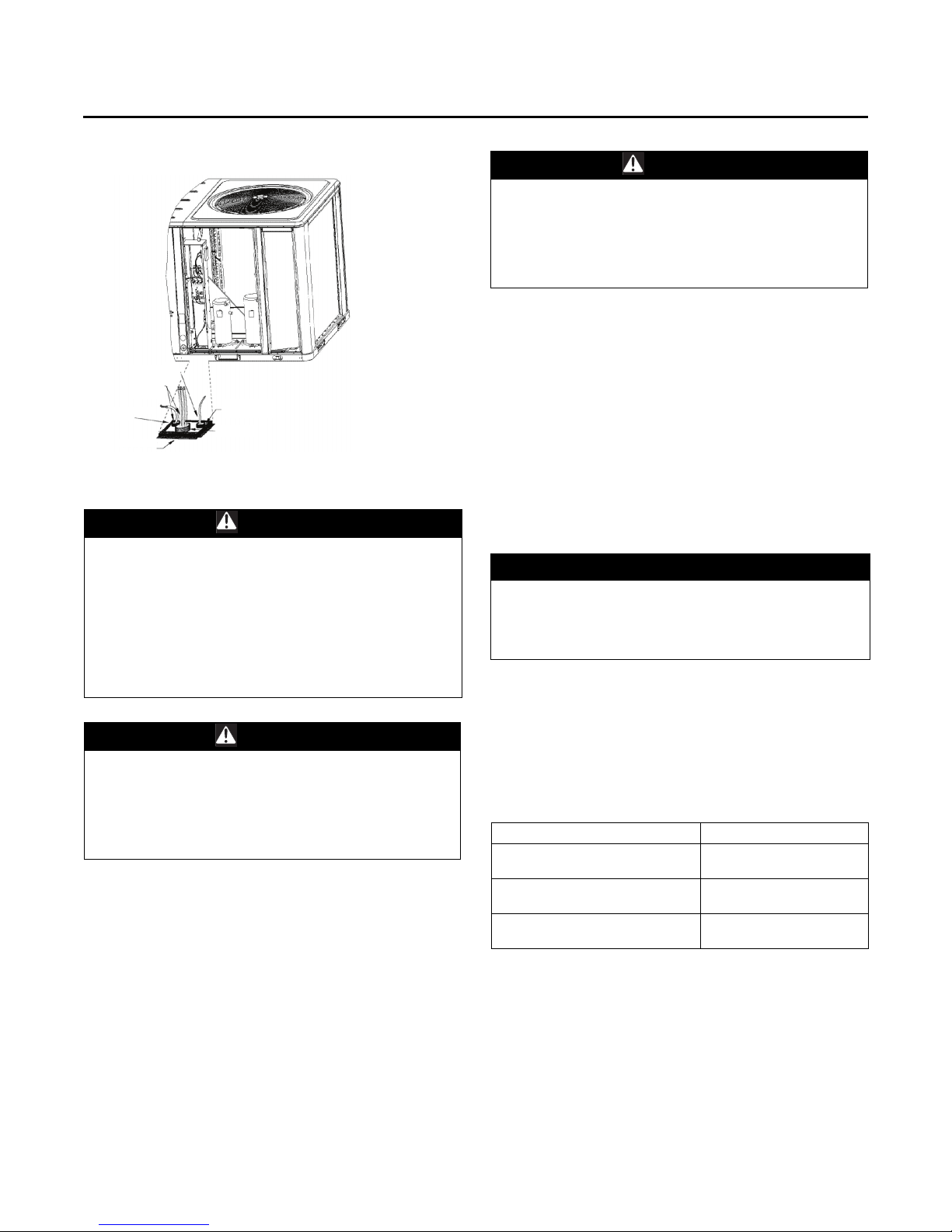
Installation
Figure 48. WSC120E, W/DHC120H
SEAL BETWEEN
WIRING AND
CONDUIT WITH
WEATHER PROOF
SEALER TO PREVENT
AIR LEAKAGE
CONTROL WIRING
CONDUIT
BLACK GASKET
FIELD POWERED
CONVENIENCE OUTLET
CONDUIT
CONTROL WIRING
CONDUIT
Field Installed Control Wiring
WARN ING
Proper Field Wiring and Grounding
Required!
Failure to follow code could result in death or serious
injury. All field wiring MUST be performed by qualified
personnel. Improperly installed and grounded field
wiring poses FIRE and ELECTROCUTION hazards. To
avoid these hazards, you MUST follow requirements for
field wiring installation and grounding as described in
NEC and your local/state electrical codes.
WARNI NG
Hazardous Voltage!
Failure to disconnect power before servicing could
result in death or serious injury. Disconnect all electric
power, including remote disconnects before servicing.
Follow proper lockout/tagout procedures to ensure the
power can not be inadvertently energized.
An overall layout of the various control options available
with the required number of conductors for each control
device is illustrated in Figure 54, p. 34.
Note: All field wiring must conform to NEC guidelines as
well as state and local codes.
Control Power Transformer
The 24 volt control power transformers are to be used only
with the accessories called out in this manual.
Transformers rated greater than 50 VA are equipped with
internal circuit breakers. If a circuit breaker trips, turn “Off”
all power to the unit before attempting to reset it.
WARNING
Hazardous Voltage!
Failure to disconnect power before servicing could
result in death or serious injury. Disconnect all electric
power, including remote disconnects before servicing.
Follow proper lockout/tagout procedures to ensure the
power can not be inadvertently energized.
The transformer is located in the control panel. The circuit
breaker is located on the left side of the transformer and
can be reset by pressing in on the black reset button.
Controls Using 24 VAC
Before installing any connecting wiring, refer to the
Dimensions and Weights chapter for the electrical access
locations provided on the unit and the following AC
conductor table for AC conductor sizing guidelines, and;
1. Use copper conductors unless otherwise specified.
2. Ensure that the AC control wiring between the controls
and the unit’s termination point does not exceed three
(3) ohms/conductor for the length of the run.
NOTICE:
Controls Using 24 VAC!
Resistance in excess of 3 ohms per conductor could
cause component failure due to insufficient AC voltage
supply.
Note: Be sure to check all loads and conductors for
grounds, shorts, and mis-wiring.
3. Do not run the AC low voltage wiring in the same
conduit with the high voltage power wiring.
4. Route low voltage wiring per the following Customer
control low voltage routing drawing.
Table 4. AC conductors
Distance from Unit to Control Recommended Wire Size
000 - 460 feet
000 - 140 m
461 - 732 feet
141 - 223 m
733 - 1000 feet
224 - 305 m
18 gauge
.75 mm
16 gauge
1.3 mm
14 gauge
2.0 mm
2
2
2
Controls Using DC Analog Input/Outputs
(Standard Low Voltage Multiconductor
Wire)
Before installing any connecting wiring between the unit
and components utilizing a DC analog input/output signal,
refer to the Dimensional information in the Dimension and
Weights chapter for the electrical access locations
provided on the unit.
1. The zone sensor module wiring table lists the
conductor sizing guidelines that must be followed
30 RT-SVX23M-EN
Page 31
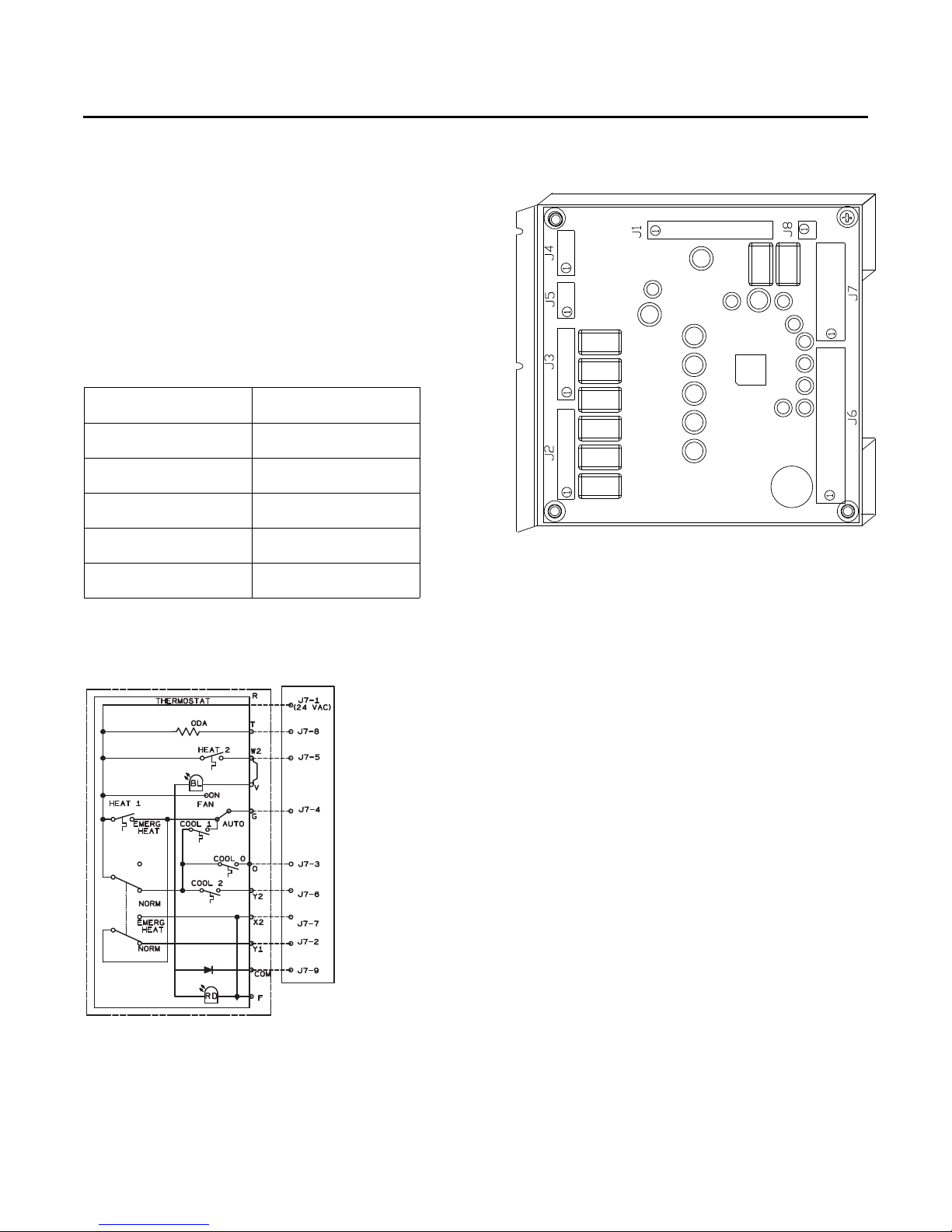
Installation
RTRM
when interconnecting the DC binary output devices
and the system components utilizing a DC analog
input/output signal to the unit.
Note: Resistance in excess of 2.5 ohms per conductor can
cause deviations in the accuracy of the controls.
2. Ensure that the wiring between controls and the unit’s
termination point does not exceed two and a half (2.5)
ohms/conductor for the length of the run.
3. Do not run the electrical wires transporting DC signals
in or around conduit housing high voltage wires.
4. Route low voltage wiring per Figure 51, p. 32.
Table 5. Zone sensor module wiring
Distance from Unit to
Control Recommended Wire Size
0 - 150 feet
0 - 45.7 m
151 - 240 feet
46 - 73.1 m
241 -385 feet
73.5 - 117.3 m
386 - 610 feet
117.7 - 185.9 m
611 - 970 feet
186.2 - 295.7 m
22 gauge
.33 mm
20 gauge
.50 mm
18 gauge
.75 mm
16 gauge
1.3 mm
14 gauge
2.0 mm
2
2
2
2
2
Figure 50. ReliaTel™ refrigeration module
Figure 49. ReliaTel™ conventional thermostat field
wiring diagram
RT-SVX23M-EN 31
Page 32
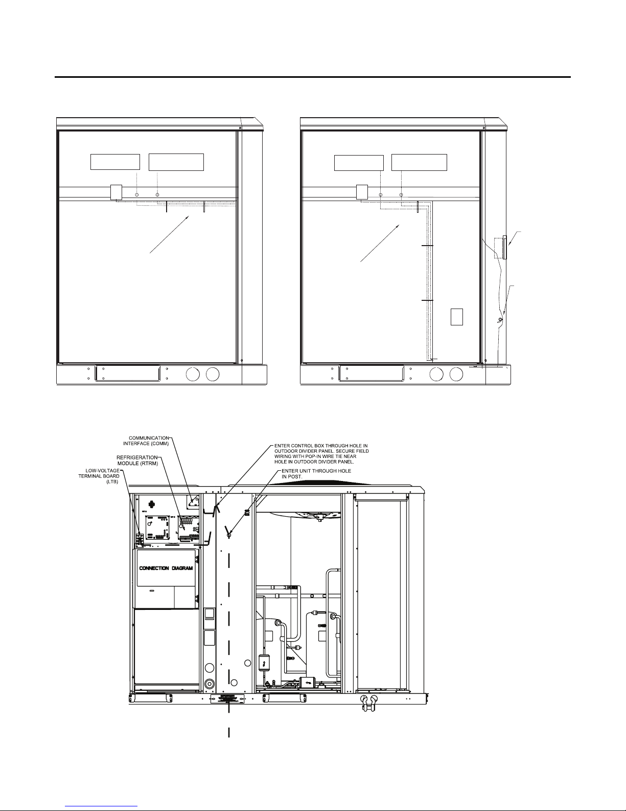
Installation
REFRIGERATION
MODULE
COMMUNICATION
INTERFACE
LTB
ReliaTel™
CONVENTIONAL WIRING
ROUTE FIELD WIRING AS SHOWN
AND SECURE WITH 2 WIRE TIES
REFRIGERATION
MODULE
COMMUNICATION
INTERFACE
LTB
ReliaTel™
TBU WIRING
ROUTE FIELD WIRING AS SHOWN
AND SECURE WITH 3 WIRE TIES
TBU
OPTION
UNPOWERED
CONVENIENCE
OUTLET
SECURE FIELD
INSTALLED WIRING
FOR CONVENIENCE
OUTLET WITH
POP-IN WIRE TIE
Figure 51. Customer control low voltage routing (all units except W/DHC120H)
Figure 52. ReliaTel™ (without TBUE) control customer wire routing (W/DHC120H)
32 RT-SVX23M-EN
Page 33
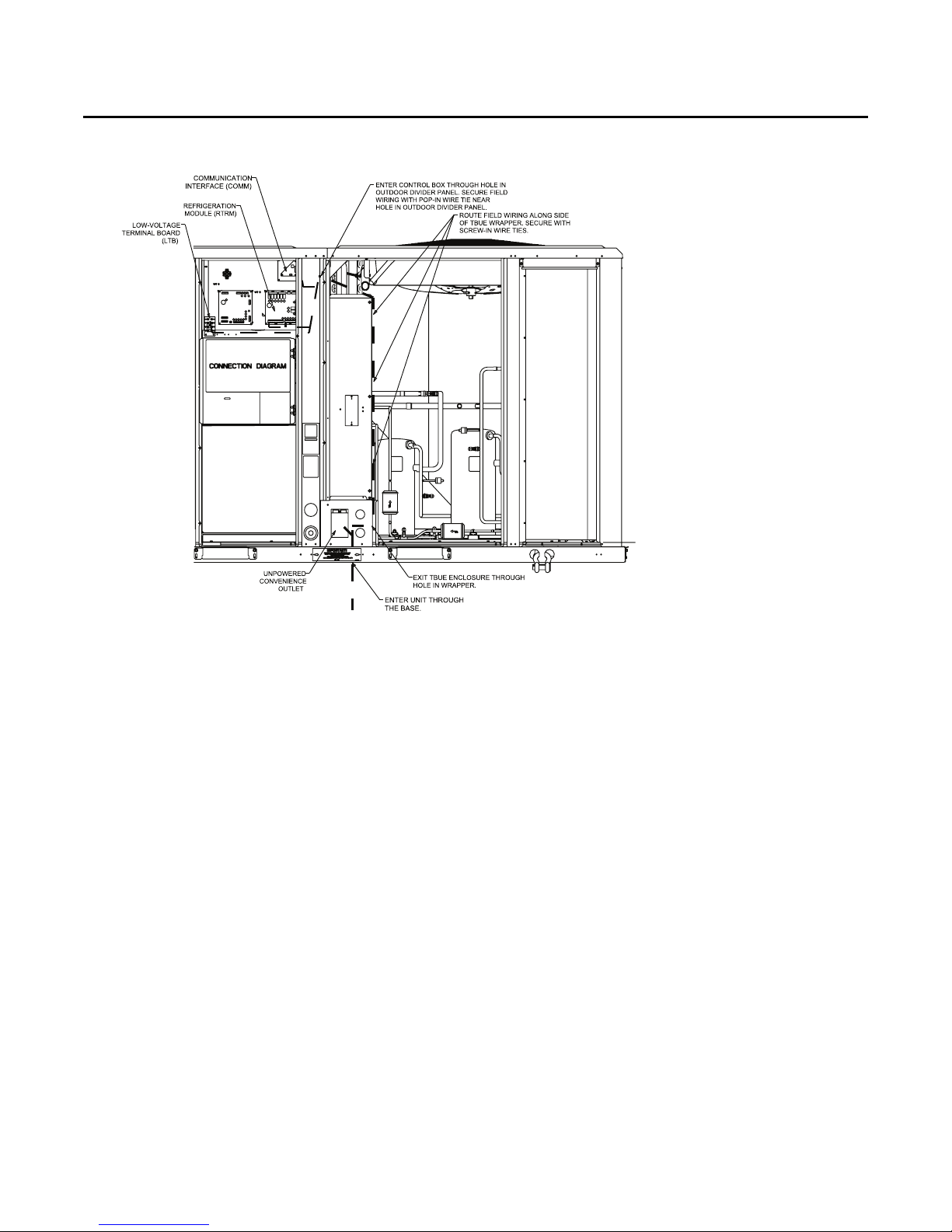
Figure 53. ReliaTel™ (with TBUE) control customer wire routing (W/DHC120H)
Installation
Space Temperature Averaging (ReliaTel™
only)
Space temperature averaging is accomplished by wiring a
number of remote sensors in a series/parallel circuit.
Using the BAYSENS016* or BAYSENS077*, at least four
sensors are required to accomplish space temperature
averaging. Example #1 illustrates two series circuits with
two sensors in each circuit wired in parallel. The square of
any number of remote sensors is required. Example #2
illustrates three sensors squared in a series/parallel circuit.
Using BAYSENS077*, two sensors are required to
accomplish space temperature averaging. Example #3
illustrates the circuit required for this sensor. The
following table lists the temperature versus resistance
coefficient for all sensors.
RT-SVX23M-EN 33
Page 34
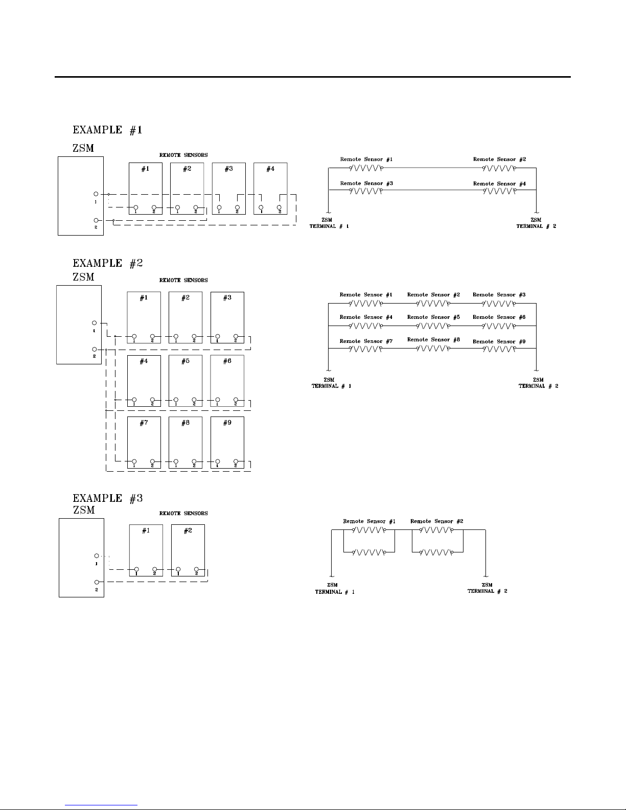
Installation
Figure 54. Examples
Note: Wiring pin numbers are for reference only. There
are multiple smoke detector systems that could
have differently numbered pins. For correct wiring
details, please refer to the specific smoke detector
literature that accompanied this unit.
34 RT-SVX23M-EN
Page 35
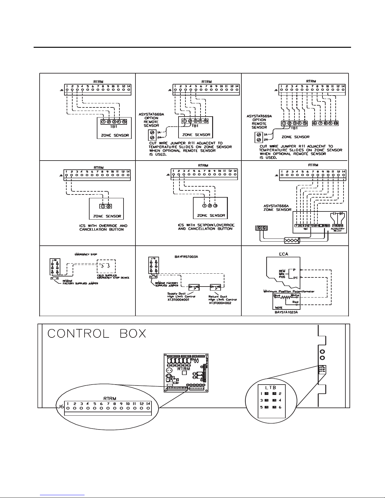
Figure 55. Typical field wiring diagrams for optional controls
BAYSENS075*
BAYSENS075*
BAYSENS119*
BAYSENS110*
BAYSENS108*
BAYSENS106*
BAYSENS073* BAYSENS074*
BAYSENS075*
ASYSTAT669A
OPTIONAL REMOTE SENSOR
Installation
RT-SVX23M-EN 35
Page 36
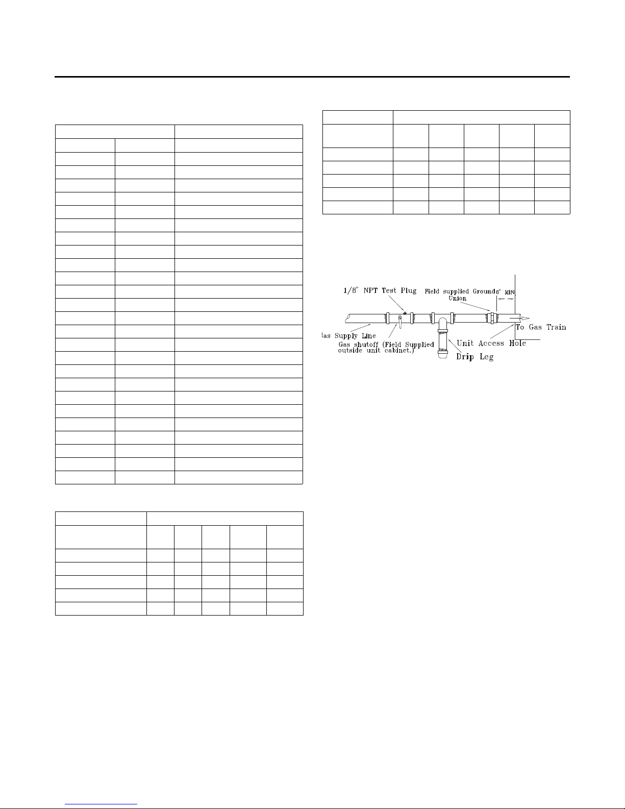
Installation
Table 6. Temperature versus resistance (temperature
vs. resistance is negative)
Temperature
Degrees F° Degrees C° Nominal Resistance
-20° -28.9° 170.1 K - Ohms
-15° -26.1° 143.5 K - Ohms
-10° -23.3° 121.4 K - Ohms
-5° -20.6° 103.0 K - Ohms
0° -17.8° 87.56 K - Ohms
5° -15.0° 74.65 K - Ohms
10° -12.2° 63.80 K - Ohms
15° -9.4° 54.66 K - Ohms
20° -6.7° 46.94 K - Ohms
25° -3.8° 40.40 K - Ohms
30° -1.1° 34.85 K - Ohms
35° 1.7° 30.18 K - Ohms
40° 4.4° 26.22 K - Ohms
45° 7.2° 22.85 K - Ohms
50° 10.0° 19.96 K - Ohms
55° 12.8° 17.47 K - Ohms
60° 15.6° 15.33 K - Ohms
65° 18.3° 13.49 K - Ohms
70° 21.1° 11.89 K - Ohms
75° 23.9° 10.50 K - Ohms
80° 26.7° 9.297 K - Ohms
85° 29.4° 8.247 K - Ohms
90° 32.2° 7.330 K - Ohms
95° 35.0° 6.528 K - Ohms
100° 37.8° 5.824 K - Ohms
Table 8. Iron pipe size (SI) millimeters
Iron Pipe Size (SI) Millimeters
Length of Pipe
(Meters)
4.6 2.15 4.98 9.76 21.23 34.54
9.1 1.47 3.39 6.82 15.14 24.06
13.7 1.21 2.80 5.63 12.31 19.82
18.3 1.07 2.43 4.89 10.76 17.27
22.9 — 2.18 4.38 9.76 15.40
Note: Capacity of Pipe of Different Diameters and Lengths in Cu. Meter Per
Hr. with Pressure Drop of 74.6 Pa and Specific Gravity of 0.60.
15 mm
Pipe
20 mm
Pipe
25 mm
Pipe
32 mm
Pipe
40 mm
Pipe
Figure 56. Schematic diagram for field gas piping to
unit
Table 7. Sizing natural gas pipe mains and branches
Iron Pipe Size (IPS) Inches
½"
¾"
1"
Length of Pipe (Ft.)
15 76 176 345 750 1220
30 52 120 241 535 850
45 43 99 199 435 700
60 38 86 173 380 610
75 77 155 345 545
Note: Capacity of Pipe of Different Diameters and Lengths in Cu. Ft. Per Hr.
with Pressure Drop of 0.3" and Specific Gravity of 0.60
Pipe
Pipe
Pipe
Pipe
36 RT-SVX23M-EN
1¼"
1½"
Pipe
Page 37
Pre-Start
Use the checklist provided below in conjunction with the
“General Unit Requirements” checklist to ensure that the
unit is properly installed and ready for operation.
WARNI NG
Hazardous Voltage w/Capacitors!
Failure to disconnect power and discharge capacitors
before servicing could result in death or serious injury.
Disconnect all electric power, including remote
disconnects and discharge all motor start/run
capacitors before servicing. Follow proper lockout/
tagout procedures to ensure the power cannot be
inadvertently energized. Verify with an appropriate
voltmeter that all capacitors have discharged.
For additional information regarding the safe discharge
of capacitors, see PROD-SVB06A-EN
• Check all electrical connections for tightness and
“point of termination” accuracy.
• Verify that the condenser airflow will be unobstructed.
• Verify that the condenser fan and indoor blower turn
freely without rubbing and are properly tightened on
the shafts.
• Check the supply fan belts for proper tension and the
fan bearings for sufficient lubrication. If the belts
require adjustment, or if the bearings need lubricating,
refer to the maintenance section of this manual for
instructions.
• Verify that a condensate trap is installed and the piping
is properly sized and pitched.
• Verify that the correct size and number of filters are in
place.
• Inspect the interior of the unit for tools and debris and
install all panels in preparation for starting the unit.
Voltage Imbalance
Three phase electrical power to the unit must meet
stringent requirements for the unit to operate properly.
Measure each leg (phase-to-phase) of the power supply.
Each reading must fall within the utilization range stamped
on the unit nameplate. If any of the readings do not fall
within the proper tolerances, notify the power company to
correct this situation before operating the unit.
Excessive three phase voltage imbalance between phases
will cause motors to overheat and eventually fail. The
maximum allowable voltage imbalance is 2%. Measure
and record the voltage between phases 1, 2, and 3 and
calculate the amount of imbalance as follows:
% Voltage Imbalance =
AV (Average Voltage) =
V1, V2, V3 = Line Voltage Readings
VD = Line Voltage reading that deviates the farthest from
the average voltage.
Example: If the voltage readings of the supply power
measured 221, 230, and 227, the average volts would be:
221 + 230 + 227
3
VD (reading farthest from average) = 221
The percentage of Imbalance equals:
100 X 226 - 221
226
The 2.2% imbalance in this example exceeds the
maximum allowable imbalance of 2.0%. This much
imbalance between phases can equal as much as a 20%
current imbalance with a resulting increase in motor
winding temperatures that will decrease motor life. If the
voltage imbalance is over 2%, notify the proper agencies
to correct the voltage problem before operating this
equipment.
100 X AV - VD
AV
Volt 1 + Volt 2 + Vo lt 3
= 226 Avg.
= 2.2%
where;
3
Electrical Phasing (Three Phase
Motors)
The compressor motor(s) and the supply fan motor are
internally connected for the proper rotation when the
incoming power supply is phased as A, B, C.
Proper electrical supply phasing can be quickly
determined and corrected before starting the unit by using
an instrument such as an Associated Research Model 45
Phase Sequence Indicator and following the steps below
:
WARNI NG
Hazardous Voltage w/Capacitors!
Failure to disconnect power and discharge capacitors
before servicing could result in death or serious injury.
Disconnect all electric power, including remote
disconnects and discharge all motor start/run
capacitors before servicing. Follow proper lockout/
tagout procedures to ensure the power cannot be
inadvertently energized. Verify with an appropriate
voltmeter that all capacitors have discharged.
For additional information regarding the safe discharge
of capacitors, see PROD-SVB06A-EN
RT-SVX23M-EN 37
Page 38
Pre-Start
• Turn the field supplied disconnect switch that provides
power to the main power terminal block or to the
“Line” side of the optional factory mounted disconnect
switch to the “Off” position.
• Connect the phase sequence indicator leads to the
terminal block or to the “Line” side of the optional
factory mounted disconnect switch as follows;
Black (phase A) to L1
Red (phase B) to L2
Yellow (phase C) to L3
• Close the field supplied main power disconnect switch
or circuit protector switch that provides the supply
power to the unit.
WARNI NG
Live Electrical Components!
Failure to follow all electrical safety precautions when
exposed to live electrical components could result in
death or serious injury. When necessary to work with
live electrical components, have a qualified licensed
electrician or other individual who has been properly
trained in handling live electrical components perform
these tasks.
Close the main power disconnect switch and the unit
mounted disconnect switch, if applicable.
ReliaTel™ Controls
Upon power initialization, the RTRM performs selfdiagnostic checks to insure that all internal controls are
functional. It also checks the configuration parameters
against the components connected to the system. The
Liteport LED located on the RTRM module is turned “On”
within one second of power-up if internal operation is
okay.
Use one of the following “Test” procedure to bypass some
time delays and to start the unit at the control panel. Each
step of unit operation can be activated individually by
temporarily shorting across the “Test” terminals for two to
three seconds. The Liteport LED located on the RTRM
module will blink when the test mode has been initiated.
The unit can be left in any “Test” step for up to one hour
before it will automatically terminate, or it can be
terminated by opening the main power disconnect switch.
Once the test mode has been terminated, the Liteport LED
will glow continuously and the unit will revert to the
“System” control.
• Observe the ABC and CBA phase indicator lights on the
face of the sequencer. The ABC indicator light will glow
if the phase is ABC. If the CBA indicator light glows,
open the disconnect switch or circuit protection switch
and reverse any two power wires.
• Restore the main electrical power and recheck the
phasing. If the phasing is correct, open the disconnect
switch or circuit protection switch and remove the
phase sequence indicator.
Compressor Crankcase Heaters
Each compressor is equipped with a crankcase heater. The
proper operation of the crankcase heater is important to
maintain an elevated compressor oil temperature during
the “Off” cycle to reduce oil foaming during compressor
starts. Oil foaming occurs when refrigerant condenses in
the compressor and mixes with the oil. In lower ambient
conditions, refrigerant migration to the compressor could
increase.
When the compressor starts, the sudden reduction in
crankcase pressure causes the liquid refrigerant to boil
rapidly causing the oil to foam. This condition could
damage compressor bearings due to reduced lubrication
and could cause compressor mechanical failures.
Before starting the unit in the “Cooling” mode, set the
system switch to the “Off” position and turn the main
power disconnect to the “On” position and allow the
crankcase heater to operate a minimum of 8 hours.
Before closing the main power disconnect switch, insure
that the “System” selection switch is in the “Off” position
and the “Fan” selection switch is in the “Auto” position.
38 RT-SVX23M-EN
Page 39
Table 9. Service test guide for component operation
Test Step Mode Fan Econ
Fan On
1
Minimum
Ventilation
2
3Cool Stage 1On
(c)
4
(c)
5
(c)
6
(c)
7
(a) The exhaust fan will turn on anytime the economizer damper position is equal to or greater than the exhaust fan setpoint.
(b) The condenser fans will operate any time a compressor is “On” providing the outdoor air temperatures are within the operating values.
(c) Steps for optional accessories and non-applicable modes in unit will be skipped.
Economizer Test
Open
Cool Stage 2 On
Reheat On Minimum On On Off Off 33K High
Heat Stage 1 On Minimum Off Off On Off 10K High
Heat Stage 2 On Minimum Off Off On On 15K High
On Selectable Off Off Off Off
On Open Off Off Off Off 3.3K Low
(a)
Minimum
Position
Setpoint 0%
Minimum
Position
Minimum
Position
Comp1 Comp 2 Heat 1 Heat 2 Ohms
Off Off Off Off
2.2K Low
(b)
On
On
(b)
Off Off Off 4.7K Low
On Off Off 6.8K
Multi-Speed Fan
Output
High (2-step cooling)
Low (2-step cooling)
components of the unit, one at a time, when a specific
Test Modes
There are three methods in which the “Test” mode can be
cycled at LTB-Test 1 and LTB-Test 2.
• Step Test Mode - This method initiates the different
components of the unit, one at a time, by temporarily
shorting across the two test terminals for two to three
seconds.
For the initial start-up of the unit, this method allows
the technician to cycle a component “On” and have up
to one hour to complete the check.
• Resistance Test Mode - This method can be used for
start-up providing a decade box for variable resistance
outputs is available. This method initiates the different
resistance value is placed across the two test
terminals. The unit will remain in the specific test mode
for approximately one hour even though the
resistance is left on the test terminals.
• Auto Test Mode - This method is not recommended for
start-up due to the short timing between individual
component steps. This method initiates the different
components of the unit, one at a time, when a jumper
is installed across the test terminals. The unit will start
the first test step and change to the next step every 30
seconds. At the end of the test mode, control of the unit
will automatically revert to the applied “System”
control method.
For unit test steps, test modes, and step resistance values
to cycle the various components, refer to Tab l e 9 , p. 3 9.
Pre-Start
Table 10. Heat Pump with Constant Volume Fan Control
Test Step Mode C1 C2 CFA CFB Heat 1 Heat 2 SOV1 Econ
1 Fan On Off Off Off Off Off Off Off Min. On Min Speed
2 Econ Off Off Off Off Off Off On 100% On Min Speed
3Cool 1OnOffNorm
4 Cool 2 On On Norm
5 Heat 1 On Off Off On Off Off Off Min. On 100%
6 Heat 2 On On Off On Off Off Off Min. On 100%
7Heat 3On/Off
8Heat 4On/Off
9 Defrost On On Off Off On Off On Min. On 100%
10 Em Heat Off Off Off Off On On Off Min. On 100%
(a) If installed
(b) Normal condenser fan staging shall remain in effect during Service Test mode
(c) Dependent on the short run timer
(d) Dependent on auxiliary heat being electric heat (On) or gas heat (Off)
RT-SVX23M-EN 39
(d)
(d)
On/Off
On/Off
(d)
(d)
(b)
Norm
(b)
Norm
Off On/Off
Off On/Off
(a)
S Fan
(b)
Off Off On Min. On 57% or 70%
(b)
Off Off On Min. On 82% or 100%
(d)
On Off Off Min. On 100%
(d)
On On Off Min. On 100%
CV Fan
Speed
Command
(c)
(c)
Page 40
Pre-Start
Table 11. Heat Pump with Single Zone VAV Fan Control
Test Step Mode C1 C2 CFA CFB Heat 1 Heat 2 SOV1 Econ
1 Fan On Off Off Off Off Off Off Off Min. On Min Speed
2 Econ Off Off Off Off Off Off On 100% On Min Speed
3Cool 1On OffNorm
4Cool 2On On Norm
(b)
(b)
Norm
Norm
(b)
(b)
Off Off On Min. On 57% or 70%
Off Off On Min. On 82% or 100%
5 Heat 1 On Off Off On Off Off Off Min. On 100%
6 Heat 2 On On Off On Off Off Off Min. On 100%
7Heat 3On/Off
8Heat 4On/Off
(d)
(d)
On/Off
On/Off
(d)
(d)
Off On/Off
Off On/Off
(d)
On Off Off Min. On 100%
(d)
On On Off Min. On 100%
9 Defrost On On Off Off On Off On Min. On 100%
10 Em Heat Off Off Off Off On On Off Min. On 100%
(a) If installed
(b) Normal condenser fan staging shall remain in effect during Service Test mode
(c) Dependent on the short run time
(d) Dependent on auxiliary heat being electric heat (On) or gas heat (Off)
Table 12. Heat Pump with Multi-Zone VAV Fan Control
Test Step Mode C1 C2 CFA CFB Heat 1 Heat 2 SOV1 Econ
1 IGV/VFD Open Off Off Off Off Off Off Off Closed Off Min Speed
2 IGV/VFD Closed Off Off Off Off Off Off Off Closed Off Min Speed
3 Fan On / Min Vent Off Off Off Off Off Off Off Min. On Min Speed
4 Econ Off Off Off Off Off Off On 100% On In Control
5Cool 1OnOffNorm
6 Cool 2 On On Norm
7 Heat 1 On Off Off On Off Off Off Min. On 100%
8 Heat 2 On On Off On Off Off Off Min. On 100%
9Heat 3On/Off
10 Heat 4 On/Off
(d)
On/Off
(d)
On/Off
(d)
(d)
11 Defrost On On Off Off On Off On Min. On 100%
12 Em Heat Off Off Off Off On On Off Min. On 100%
(a) If installed
(b) Supply Fan Speed controlled to duct static pressure
(c) Normal condenser fan staging shall remain in effect during Service Test mode
(d) Dependent on auxiliary heat being electric heat (On) or gas heat (Off)
(c)
Norm
(c)
Norm
Off On/Off
Off On/Off
(c)
(c)
Off Off On Min. On In Control
Off Off On Min. On In Control
(d)
On Off Off Min. On 100%
(d)
On On Off Min. On 100%
(a)
S Fan
(a)
S Fan
CV Fan
Speed
Command
(c)
(c)
CV Fan
Speed
Command
(b)
(b)
(b)
40 RT-SVX23M-EN
Page 41

Unit Start-Up
Sequence of Operation
Units are offered with two control options,
electromechanical or ReliaTel™.
Note: Refer to the unit nameplate: If the 9th digit of the
model number = R, proceed with the ReliaTel™
Controls section within this chapter. If the 9th digit
of the model number = E, proceed with the
Electromechanical Controls section within this
chapte r.
Note: The optional condensate overflow switch (COF)
will shut the unit down if the float is raised and the
switch is closed.
ReliaTel™ Controls
ReliaTel™ Controls - Constant Volume
(CV)
ReliaTel™ control is a microelectronic control feature,
which provides operating functions that are significantly
different than conventional electromechanical units. The
master module is the ReliaTel™ refrigeration module
(RTRM).
The RTRM provides compressor anti-short cycle timing
functions through minimum “Off” and “On” timing to
increase reliability, performance and to maximize unit
efficiency.
Upon power initialization, the RTRM performs selfdiagnostic checks to insure that all internal controls are
functioning. It checks the configuration parameters
against the components connected to the system.
The LED located on the RTRM module is turned “On”
within one second after power-up if all internal operations
are okay.
ReliaTel™ Control Cooling without an
Economizer
When the system switch is set to the “Cool” position and
the zone temperature rises above the cooling setpoint
control band, the RTRM energizes the (K9) relay coil
located on the RTRM. When the K9 relay contacts close,
the compressor contactor (CC1) coil is energized provided
the low pressure control (LPC1), high pressure control
(HPC1) and discharge line thermostat (TDL 1) are closed.
When the CC1 contacts close, compressor (CPR1) and the
outdoor fan motor (ODM) start to maintain the zone
temperature to within ± 2ºF of the sensor setpoint at the
sensed location.
If the first stage of cooling can not satisfy the cooling
requirement, the RTRM energizes the (K10) relay coil
located on the RTRM. When the (K10) relay contacts close,
the compressor contactor (CC2) coil is energized provided
the low pressure control (LPC2), high pressure control
(HPC2) and discharge line thermostat (TDL 2) are closed.
When the CC2 contacts close, compressor (CPR2) starts to
maintain the zone temperature to within ± 2ºF of the sensor
setpoint at the sensed location.
Three-Stages of Cooling
Note: High efficiency units only.
When the unit is configured for three-stage cooling, and
the system switch is set to the cool position and the zone
temperature rises above the cooling setpoint control band,
the RTRM energizes the (K10) relay coil located on the
RTRM. When the (K10) relay contacts close, compressor
contactor (CC2) is energized. This is the smaller of the two
compressors (CPR2). This staging order is opposite
standard staging order.
If the first stage of cooling can not satisfy the cooling
requirement, the RTRM energizes the (K9) relay coil and
de-energizes the (K10) relay coil on the RTRM. Compressor
contactor (CC1) is energized, bringing on the larger of the
two compressors (CPR1). Compressor contactor (CC2) is
de-energized, turning off the smaller compressor.
If the second stage of cooling can not satisfy the cooling
requirement, the RTRM keeps the (K9) relay coil energized
and energizes the (K10) relay coil. Compressor contactors
(CC1) and (CC2) are energized, and both compressors
(CPR1 and CPR2).
Lead/Lag is disabled with three-stage cooling. A unit
configured for three-stage cooling and controlled with a
thermostat will operate as a two-stage unit.
ReliaTel™ Control Evaporator Fan
Operation (for Gas Units)
When the fan selection switch is set to the “Auto” position,
the RTRM energizes the (K6) relay coil approximately 1
second after energizing the compressor contactor coil
(CC1) in the cooling mode. In the heating mode, the RTRM
energizes the (K6) relay coil approximately 45 second after
gas ignition. Closing the (K6) contacts on the RTRM
energizes the indoor fan relay (F) coil to start the indoor fan
motor (IDM).
The RTRM de-energizes the fan relay (F) approximately 60
seconds after the cooling requirement has be satisfied to
enhance unit efficiency. When the heating cycle is
terminated, the indoor fan relay (F) coil is de-energized
approximately 90 seconds after the heating requirement.
When the fan selection switch is set to the “On” position,
the RTRM keeps the indoor fan relay coil (F) energized for
continuous fan motor operation.
RT-SVX23M-EN 41
Page 42

Sequence of Operation
When the unit is equipped with the optional clogged filter
switch, wired between terminals J7-3 and J7-4 on the
ReliaTel™ options module (RTOM), the RTRM produces an
analog output if the clogged filter switch (CFS) closes for
two minutes after a request for fan operation. When the
system is connected to a remote panel, the “SERVICE”
LED will be turned on when this failure occurs.
ReliaTel™ Control Evaporator Fan
Operation (for Cooling Only Units)
When the fan selection switch is set to the “Auto” position,
the RTRM energizes the (K6) relay coil approximately 1
second after energizing the compressor contactor coil
(CC1) in the cooling mode. In the heating mode, the RTRM
energizes the (K6) relay coil approximately 1 second
before energizing the electric heat contactors. Closing the
(K6) contacts on the RTRM energizes the indoor fan relay
(F) coil to start the indoor fan motor (IDM). The RTRM deenergizes the fan relay (F) approximately 60 seconds after
the cooling requirement has be satisfied to enhance unit
efficiency.
When the heating cycle is terminated, the indoor fan relay
(F) coil is de-energized at the same time as the heater
contactors.
When the fan selection switch is set to the “On” position,
the RTRM keeps the indoor fan relay coil (F) energized for
continuous fan motor operation.
When the unit is equipped with the optional clogged filter
switch, wired between terminals J7-3and J7-4 on the
ReliaTel™ options module (RTOM), the RTRM produces an
analog output if the clogged filter switch (CFS) closes for
two minutes after a request for fan operation.
When the system is connected to a remote panel, the
“SERVICE” LED will be turned on when this failure occurs.
Low Ambient Operation
Note: For ReliaTel™ units only
During low ambient operation, outside air temperature
below 55°F, the RTRM will cycle the compressor and
outdoor fan motor “Off” for approximately 3 minutes after
every 10 minutes of accumulated compressor run time.
The indoor fan motor (IDM) will continue to operate during
this evaporator defrost cycle (EDC) and the compressor
and outdoor fan will return to normal operation once the
defrost cycle has terminated and the compressor “Off”
time delay has been satisfied.
Note: Units with the dehumidification option - When in
dehumidification mode, the unit will not cycle as
described above. The unit will run continuously in
dehumidification mode at all ambient conditions
above 40ºF. Dehumidification is disabled at
ambient conditions below 40ºF.
Multi-Speed Indoor Motor
Note: Multi-speed indoor fan available only on 6, 7.5 (dual
compressor) & 8.5 tons high efficiency, and 10 ton
products with ReliaTel™ controls.
Note: Multi-speed indoor fan standard for 17 Plus.
Models configured for the multi-speed indoor motor will
be controlled via the 0-10 Vdc or PWC indoor fan speed
output located on the RTOM. R136 (DA COOL_FAN SPD)
potentiometer on the RTOM sets the maximum motor
speed. Note that the potentiometer voltage readings can
be verified via 2-position harness connector located
adjacent to the RTOM. The unit schematic will illustrate the
exact location. Use a DC voltmeter to read the voltage
between the two terminals. Provisions have been made in
Service TEST Mode to allow for maximum motor speed
adjustment. Motor may be adjusted using modes listed
below. Reference the RPM table in the Performance Data
section for fan speed.
1. TEST Mode Cool 2; 2-Step Cool applications only
2. TEST Mode Cool 3; 3-Step Cool applications only
Adjust R136 potentiometer clockwise to increase or
counterclockwise to decrease motor speed.
Refer to the Fan Output% list below for supply fan output
associated with each unit function:
Fan Output%
• Ventilation Only 50%
• Economizer Cooling 65%
• Cool 1 (C1 Energized) 65%
• Cool 2 (C1 + C2) 100% (2-Steps of Cooling)
• Cool 2 (C1 or C2) 65% (3-Steps of Cooling)
• Cool 3 (C1 + C2 Energized) 100%
• Dehumidification Fan Speeds and Enhanced 53%
•Heat 100%
Multi-Zone VAV Sequence of
Operation
Supply Air Pressure Control
ReliaTel™ Option Module Control (RTOM)
Supply fan is driven by a pulse-width modulation (PWM)
signal from the RTOM.
Note: PWM = 3 to 5 tons
A pressure transducer measures duct static pressure, and
the supply fan is modulated to maintain the supply air
static pressure within an adjustable user-defined range.
The range is determined by the supply air pressure
setpoint and supply air pressure deadband, which are set
through a unit mounted potentiometer or remote panel.
The RTOM provides supply fan motor speed modulation.
42 RT-SVX23M-EN
Page 43

Sequence of Operation
The supply fan will accelerate or decelerate as required to
maintain the supply static pressure setpoint.
Supply Air Static Pressure Limit
The control of the supply fan and VAV boxes are
coordinated, with respect to time, during unit start up and
transition to/from Occupied/Unoccupied modes to
prevent overpressurization of the supply air ductwork.
However, if for any reason the supply air pressure exceeds
the fixed supply air static pressure limit of 3.5" W.C., the
supply fan is shut down and the VAV boxes are closed. The
unit is then allowed to restart three times. If the
overpressurization condition occurs on the fourth time,
the unit is shut down and a manual reset diagnostic is set
and displayed at any of the remote panels with LED status
lights or communicated to the Integrated Comfort system.
Supply Air Temperature Controls
Cooling/Economizer
During occupied cooling mode of operation, the
economizer (if available) and primary cooling are used to
control the supply air temperature. The supply air
temperature setpoint is user-defined at the unit mounted
VAV Setpoint Potentiometer or at the remote panel. If the
enthalpy of the outside air is appropriate to use “free
cooling”, the economizer will be used first to attempt to
satisfy the supply setpoint. On units with economizer, a
call for cooling will modulate the fresh air dampers open.
The rate of economizer modulation is based on deviation
of the discharge temperature from setpoint, i.e., the further
away from setpoint, the faster the fresh air damper will
open. Note that the economizer is only allowed to function
freely if ambient conditions are below the enthalpy control
setting or below the return air enthalpy if unit has
comparative enthalpy installed. If outside air is not
suitable for “economizing”, the fresh air dampers drive to
the minimum open position. A field adjustable
potentiometer on the Economizer Actuator, or a remote
potentiometer can provide the input to establish the
minimum damper position. At outdoor air conditions
above the enthalpy control setting, primary cooling only is
used and the fresh air dampers remain at minimum
position. If the unit does not include an economizer,
primary cooling only is used to satisfy cooling
requirements.
Supply Air Setpoint Reset
Supply air reset can be used to adjust the supply air
temperature setpoint on the basis of a zone temperature,
return air temperature, or on outdoor air temperature.
Supply air reset adjustment is available on the unit
mounted VAV setpoint potentiometer for supply air
cooling control.
Reset Based on Outdoor Air Temperature
Outdoor air cooling reset is sometimes used in
applications where the outdoor temperature has a large
effect on building load. When the outside air temperature
is low and the building cooling load is low, the supply air
setpoint can be raised, thereby preventing subcooling of
critical zones. This reset can lower usage of primary
cooling and result in a reduction in primary cooling energy
usage There are two user-defined parameters that are
adjustable through the VAV Setpoint Potentiometer: reset
temperature setpoint and reset amount. The amount of
reset applied is dependent upon how far the outdoor air
temperature is below the supply air reset setpoint. The
amount is zero where they are equal and increases linearly
toward the value set at the reset amount input. The
maximum value is 20°F. If the outdoor air temperature is
more than 20°F below the reset temperature setpoint the
amount of reset is equal to the reset amount setpoint.
Reset Based on Zone or Return Temperature
Zone or return reset is applied to the zone(s) in a building
that tends to overcool or overheat. The supply air
temperature setpoint is adjusted based on the
temperature of the critical zone(s) or the return air
temperature. This can have the effect of improving
comfort and/or lowering energy usage. The user-defined
parameters are the same as for outdoor air reset. Logic for
zone or return reset control is the same except that the
origins of the temperature inputs are the zone sensor or
return sensor respectively. The amount of reset applied is
dependent upon how far the zone or return air
temperature is below the supply air reset setpoint. The
amount is zero where they are equal and increases linearly
toward the value set at the reset amount potentiometer on
the VAV setpoint potentiometer. The maximum value is
3°F. If the return or zone temperature is more than 3°F
below the reset temperature setpoint the amount of reset
is equal to the reset amount setpoint.
Zone Temperature Control
Unoccupied Zone Cooling
During unoccupied mode, the unit is operated as a CV unit.
VAV boxes are driven full open and the supply fan is
commanded to full speed. The unit controls zone
temperature to the Unoccupied zone cooling setpoints.
Daytime Warm-up
During occupied mode, if the zone temperature falls to a
temperature three degrees below the Morning Warm-up
setpoint, Daytime Warm-up is initiated. The system
changes to CV heating (full unit airflow), the VAV boxes are
fully opened and the CV heating algorithm is in control
until the Morning Warm-up setpoint is reached. The unit is
then returned to VAV cooling mode. The Morning Warmup setpoint is set at the unit mounted VAV Setpoint
potentiometer or at a remote panel.
Morning Warm-up (MWU)
Morning warm-up control (MWU) is activated whenever
the unit switches from unoccupied to occupied and the
zone temperature is at least 1.5°F below the MWU setpoint.
When MWU is activated the VAV box output will be
RT-SVX23M-EN 43
Page 44
Sequence of Operation
energized for at least 6 minutes to drive all boxes open, the
supply fan is commanded to full speed, and full heat (gas
or electric) is energized. When MWU is activated the
economizer damper is driven fully closed. When the zone
temperature meets or exceeds the MWU setpoint minus
1.5°F, the heat will be turned or staged down. When the
zone temperature meets or exceeds the MWU setpoint
then MWU will be terminated and the unit will switch over
to VAV cooling.
Variable Air Volume Applications
(Single Zone VAV)
Supply Fan Output Control
Units configured for Single Zone VAV will be controlled via
the 0-10Vdc Indoor Fan Speed output located on the
RTOM. R136 (DA COOL_FAN SPD) potentiometer on the
RTOM sets the maximum motor speed. Note that the
potentiometer voltage readings can be verified via 2position harness connector located adjacent to the RTOM.
The unit schematic will illustrate the exact location. Use a
DC voltmeter to read the voltage between the two
terminals. Reference the RPM table in the Performance
Data section for fan speed.
• Use Service TEST Mode to adjust maximum motor
speed using modes listed below.
1. TEST Mode Cool 2; 2-Step Cool applications only
2. TEST Mode Cool 3; 3-Step Cool applications only
• Adjust DA COOL_FAN SPD potentiometer clockwise to
increase or counterclockwise to decrease motor speed.
• The control will scale the 0-10Vdc output from the
RTOM linearly to control between the 50%-100%
controllable range based on the space cooling
demand.
Minimum Supply Fan Output
• Refer to the table below for details on minimum supply
fan output signals associated with each unit function.
• Minimum Fan Output%
• Ventilation Only 50%
• Economizer Cooling 65%
• Cool 1 (C1 Energized) 65%
• Cool 2 (C1 + C2) 82% (2-Steps of Cooling)
• Cool 2 (C1 or C2) 65% (3-Steps of Cooling)
• Cool 3 (C1 + C2 Energized) 82%
•Heat 100%
Discharge Air Cool Setpoint Adjustment
• Single Zone VAV units will require traditional zone
heating (if heat installed) and cooling setpoints that are
used on single speed units in addition to a new
setpoint: Discharge Air Cool Setpoint limit. Discharge
Air Cool Setpoints will be customer selectable via a
potentiometer (DACR) adjacent to the RTOM with a
range of 40- 70°F.
• The table below lists the discharge air cool setpoints on
the DACR.
Note: The recommended setting is 50°F.
Table 13. Discharge air cool setpoints (DACR)
Setpoint (°F) Voltage (Vdc)
40 - <0.1 55 - 1.65
41 - 0.2 56 - 1.7
42 - 0.3 57 - 1.75
43 - 0.45 58 - 1.83
44 - 0.55 59 - 1.9
45 - 0.7 60 - 1.95
46 - 0.8 61 - 2
47 - 0.95 62 - 2.05
48 - 1.05 63 - 2.1
49 - 1.15 64 - 2.13
50 - 1.25 65 - 2.17
51 - 1.3 66 - 2.21
52 - 1.35 67 - 2.27
53 - 1.45 68 - 2.3
54 - 1.55 69 - 2.35
70 - >2.4
ReliaTel™ Control Cooling with an
Economizer
The economizer is utilized to control the zone temperature
providing the outside air conditions are suitable. Outside
air is drawn into the unit through modulating dampers.
When cooling is required and economizing is possible, the
RTRM sends the cooling request to the unit economizer
actuator (ECA) to open the economizer damper. The RTRM
tries to cool the zone utilizing the economizer to slightly
below the zone temperature setpoint. If the mixed air
sensor (MAS) senses that the mixed air temperature is
below 53°F, the damper modulates toward the closed
position. If the zone temperature continues to rise above
the zone temperature setpoint controlband and the
economizer damper is full open, the RTRM energizes the
compressor contactor (CC1). If the zone temperature
continues to rise above the zone temperature setpoint
controlband and the economizer damper is fully open, the
RTRM energizes the compressor contactor (CC2).
Multi-Speed Fan
When economizing alone or with 1st stage cooling the
indoor motor will operate at low speed. If economizing
and 2nd stage cooling requested, the indoor motor will
transition from low to high speed.
Single Zone VAV
The indoor motor will vary the indoor motor speed to
optimize minimum fan speed for the cooling demand in all
44 RT-SVX23M-EN
Page 45

Sequence of Operation
modes (Economizer Only, Economizer +1st Stage Cooling,
or Economizer + 1st/2nd Stage Cooling).
The ECA continues to modulate the economizer damper
open/closed to keep the mixed air temperature that is
calculated by the RTRM.
If economizing is not possible, the ECA drives the damper
to the minimum position setpoint when the indoor fan
relay (F) is energized and allows mechanical cooling
operation.
When the unit is equipped with the optional fan failure
switch, wired between terminals J7-5 and J7-6 on the
RTOM, the RTRM will stop all cooling functions and
produce an analog output if the fan failure switch (FFS)
does not open within 40 seconds after a request for fan
operation. When the system is connected to a remote
panel, the “SERVICE” LED will flash when this failure
occurs.
ReliaTel™ Control Dehumidification
Single Compressor Units
On a call for dehumidification, the reheat valve is
energized and the compressor is turned on. When the
humidity control setpoint is satisfied, the valve is deenergized and the compressor is turned off. If there is a call
for cooling or heating from the space temperature
controller, i.e. zone sensor or thermostat, while in reheat,
the reheat valve is de-energized and the compressor
continues to run, or the heat is turned on. The 3 minute
compressor on and off times are still active during
compressor operation.
Dehumidification Coil Purge Cycle
On multiple circuit units with dehumidification/reheat
configured, a purge cycle will be active for compressor
reliability. The purpose of this function is to properly
distribute refrigerant and lubricant throughout the system
by temporarily switching to the unused section of the coil
for 3 minutes (purge cycle). The function operates as
follows:
1. A purge cycle will be initiated after 90 minutes of
accumulated compressor run time in only one mode:
cooling or dehumidification, without transitioning to
the other mode.
2. A purge cycle will consist of transitioning to the mode
that hasn’t run in 90 minutes of total compressor
operation. The cycle will last for a period of 3 minutes.
3. The 90-minute cycle count will be reset anytime there
is a normal transition between cooling and
dehumidification. Transitioning from one of these
modes to any other mode (off or heat) will not reset the
counter.
4. If the purge cycle is a cooling cycle, only the first circuit
will be activated. If it is a dehumidification cycle then
the normal 2-compressor dehumidification mode
cycle will be used.
5. The purge cycle will ignore the low ambient
dehumidification lockout feature.
6. A purge cycle takes priority over normal cooling or
dehumidification requests, but will discontinue for all
high priority lockouts and alarms.
Dual Compressor Units
The dehumidification cycle is only permitted above 40ºF
and below 100°F and is not permitted during a heating
cycle or during a demand for 2nd stage cooling. Otherwise,
when an installed zone humidity sensor indicates a
relative humidity equal to or greater than the RH set point
as adjusted on the ReliaTel™ options module (RTOM), a
dehumidification cycle is initiated. The sequence of
operation for the dehumidification cycle is identical to that
of the second stage ReliaTel™ cooling cycle, except that
the hot gas reheat valve (RHV) is energized, allowing air
from the evaporator to be reheated. Also, any installed
fresh air damper is driven to minimum position.The
dehumidification cycle is terminated by initiation of a
heating cycle or a 2
humidity is reduced to 5% below the R.H. set point. In the
absence of a zone humidity sensor input, an on/off input
from a zone humidistat is used to initiate/terminate the
dehumidification cycle.
Dehumidification takes priority over a call for one-stage
cooling.
Heating or two-stage cooling takes priority over
dehumidification, and a relative humidity sensor takes
priority over a humidistat.
nd
stage cooling cycle or when zone
ReliaTel™ Control Cooling with an
Economizer
The economizer is utilized to control the zone temperature
providing the outside air conditions are suitable. Outside
air is drawn into the unit through modulating dampers.
When cooling is required and economizing is possible, the
RTRM sends the cooling request to the unit economizer
actuator (ECA) to open the economizer damper. The RTRM
tries to cool the zone utilizing the economizer to slightly
below the zone temperature setpoint. If the mixed air
sensor (MAS) senses that the mixed air temperature is
below 53°F, the damper modulates toward the closed
position. If the zone temperature continues to rise above
the zone temperature setpoint control band and the
economizer damper is full open for 5 minutes, the RTRM
energizes the compressor contactor (CC1). If the zone
temperature continues to rise above the zone temperature
setpoint control band and the economizer damper is fully
open, the RTRM energizes the compressor contactor
(CC2).
The ECA continues to modulate the economizer damper
open/closed to keep the mixed air temperature that is
calculated by the RTRM.
If economizing is not possible, the ECA drives the damper
to the minimum position setpoint when the indoor fan
RT-SVX23M-EN 45
Page 46
Sequence of Operation
relay (F) is energized and allows mechanical cooling
operation.
When the unit is equipped with the optional fan failure
switch, wired between terminals J7-5 and J7-6 on the
RTOM, the RTRM will stop all cooling functions and
produce an analog output if the fan failure switch (FFS)
does not open within 40 seconds after a request for fan
operation. When the system is connected to a remote
panel, the “SERVICE” LED will flash when this failure
occurs.
Note: For units equipped with the dehumidification
option, if the unit is economizing, the damper
resets to minimum position while in
dehumidification mode.
Economizer Set-Up
Adjusting the minimum position potentiometer located on
the unit economizer actuator (ECA) sets the required
amount of ventilation air.
Two of the three methods for determining the suitability of
the outside air can be selected utilizing the enthalpy
potentiometer on the ECA, as described below:
1. Ambient temperature - controlling the economizing
cycle by sensing the outside air dry bulb temperature.
The following table lists the selectable dry bulb values
by potentiometer setting.
2. Reference enthalpy - controlling the economizer cycle
by sensing the outdoor air humidity. The following
table lists the selectable enthalpy values by
potentiometer setting. If the outside air enthalpy value
is less than the selected value, the economizer is
allowed to operate.
3. Comparati ve enthalpy - utilizing a humidity sensor and
a temperature sensor in both the return air stream and
the outdoor air stream, the unit control processor
(RTRM) will be able to establish which conditions are
best suited for maintaining the zone temperature, i.e.
indoor conditions or outdoor conditions. The
potentiometer located on the ECA is non-functional
when both the temperature and humidity sensors are
installed.
Table 14. Potentiometer settings
Potentiometer
Setting Dry Bulb Reference Enthalpy
A 73°F (22.8ºC) 27 Btu/lb (63 kJ/kg)
B 70°F (21.1ºC) 25 Btu/lb (58 kJ/kg)
(a)
C 67°F
D 63°F (17.2ºC) 22 Btu/lb (51 kJ/kg)
E 55ºF (12.8ºC) 19 Btu/lb (44 kJ/kg)
(a) Factory settings
(19.4ºC)
23 Btu/lb (53 kJ/kg)
ReliaTel™ Control Heating Operation (for
Cooling Only Units)
When the system switch is set to the “Heat” position and
the zone temperature falls below the heating setpoint
control band, the RTRM energizes (K1) relay coil. When the
(K1) relay contacts close, located on the RTRM, the first
stage electric heat contactor (AH or AH & CH) is energized.
If the first stage of electric heat can not satisfy the heating
requirement, the RTRM energizes (K2) relay coil. When the
(K2) relay contacts close, located on the RTRM, the second
stage electric heat contactor (BH) is energized, if
applicable. The RTRM cycles both the first and second
stages of heat “On” and “Off” as required to maintain the
zone temperature setpoint.
ReliaTel™ Control Heating Operation (for
Gas Units)
When the system switch is set to the “Heat” position and
the zone temperature falls below the heating setpoint
control band, a heat cycle is initiated when the RTRM
communicates ignition information to the Ignition module
(IGN).
Ignition Module
Two-stage (IGN) runs self-check (including verification that
the gas valve is de-energized). (IGN) checks the high-limit
switches (TC01 & TC02) for normally closed contacts, the
pressure switch (PS) for normally open contacts, and the
flame rollout (FR) switch for continuity. (IGN) energizes
inducer blower on high speed to check pressure switch
closure. If the pressure switch is closed, the inducer blower
starts a 20-second pre-purge (15 seconds on high speed
followed by 5 seconds on low speed). If the pressure
switch (PS) is still open, the inducer blower will continue to
be energized on high speed until pressure switch closure.
After pre-purge completes, the (IGN) energizes the first
stage of the gas valve, initiates spark for 2 seconds
minimum, 7 seconds maximum (ignition trial) and detects
flame and de-energizes spark. From this point, a fixed 45
second indoor blower delay on timing starts. After the
indoor blower delay on is completed, the (IGN) energizes
the indoor blower. The (IGN) enters a normal operating
loop where all inputs are continuously monitored. If the
first stage of gas heat can not satisfy the heating
requirement, the thermostat closes W2. The (IGN)
energizes the second stage of the gas valve and the second
stage of inducer blower. When the zone thermostat is
satisfied, the (IGN) de-energizes the gas valve. The (IGN)
senses loss of flame. The (IGN) initiates a 5 second inducer
blower post purge. The (RTRM) initiates a second indoor
blower delay off.
If the burner fails to ignite, the ignition module will attempt
two retries before locking out. The green LED will indicate
a lock out by two fast flashes. An ignition lockout can be
reset by;
46 RT-SVX23M-EN
Page 47
1. Opening for 3 seconds and closing the main power
disconnect switch.
2. Switching the “Mode” switch on the zone sensor to
“OFF” and then to the desired position.
3. Allowing the ignition control module to reset
automatically after one hour. Refer to the “Ignition
Control Module Diagnostics” section for the LED
diagnostic definitions.
When the fan selection switch is set to the “Auto” position,
the RTRM energizes the indoor fan relay (F) coil
approximately 30 second after initiating the heating cycle
to start the indoor fan motor (IDM).
Table 15. Ignition module diagnostics
Steady light
Blinking at
continuous
steady rate
One blink
Two blinks
Three blinks
Four blinks
Five blinks
Six blinks
Seven blinks
Module is powered up, but no active call for
heat.
Active call for heat.
Loss of communication.
System lockout (failure to ignite, no spark, low/
no gas pressure, etc.)
Pressure switch (no vent air flow, bad CBM,
closed at initial call for heat). Auto reset.
High limit (excessive heat in combustion
chamber, low airflow). Auto reset.
Flame sensed and gas valve not energized or
flame sensed and no call for heat.
Flame rollout (CBM failure, incorrect gas
pressure, incorrect primary air). Requires
manual reset of the switch.
ReliaTel™ module will communicate a heat fail
diagnostic back to the RTRM.
Sequence of Operation
Drain Pan Condensate Overflow Switch
(Optional)
This input incorporates the condensate overflow switch
(COF) mounted on the drain pan and the ReliaTel™ options
module (RTOM). When the condensate level reaches the
trip point for 6 continuous seconds, the RTOM will shut
down all unit function until the overflow condition has
cleared. The unit will return to normal operation after 6
continuous seconds with the COF in a non-tripped
condition. If the condensate level causes the unit to
shutdown more than 2 times in a 3 day period, the unit will
be locked-out of operation. A manual reset of the
diagnostic system through the zone sensor or Building
Automation System (BAS) will be required. Cycling unit
power will also clear the fault.
RT-SVX23M-EN 47
Page 48
Sequence of Operation - Heat Pumps
Heating Operation
When the system switch is set to the “Heat” MODE, the
RTRM energizes relay (K3). When the normally open (K3)
contacts open, the switch over valves (SOV1 & 2) are deenergized. When the zone temperature falls below the
heating setpoint controlband, the RTRM energizes the (K9)
& (K10) relay coils on the RTRM. When the (K9) relay
contacts close, the compressor contactor (CC1) coil is
energized provided the low pressure control (LPC1), high
pressure control (HPC1) and discharge line thermostat
(TDL 1) are closed. When the CC1 contacts close,
compressor (CPR1) and the outdoor fan motor (ODM)
starts provided the normally open (ODF) relay contacts are
closed.
The RTRM “Smart Recovery” function monitors the rate at
which the zone temperature is changing every 9 minutes
during the operating heating cycle. If the zone temperature
is rising at a rate greater than 6ºF per hour, no additional
heat is requested (auxiliary heat). If not, the RTRM
energizes the first stage auxiliary heat. A minimum of 10
seconds “Off” time must have elapsed between heater
cycles. If mechanical heat and first stage auxiliary heat
cannot provide the 6 F recovery rate, the RTRM energizes
second stage auxiliary heat, if applicable. The RTRM
continues to monitor the rate of change and stages the
electric heat “Off” as it determines that the mechanical
heat (compressor operation) is sufficient.
Demand Defrost
Demand defrost is a standard feature which permits
defrost whenever coil icing conditions begin to
significantly reduce unit capacity. To permit defrost, the
outdoor temperature must be below 52ºF, coil temperature
must be below 33ºF, and the delta temperature F must
exceed a RTRM calculated value. After 30 minutes of run
time under defrost permit conditions, the RTRM initiates a
defrost cycle. Upon termination of this cycle, the RTRM
monitors the outdoor temperature (ODT) and the coil
temperature (CT) and calculates the delta temperature F
(ODT - CT). This value is stored in memory and the RTRM
calculates a defrost initiate value. The RTRM continually
compares the delta temperature F to the defrost initiate
value. Once the delta tee reaches the initiate value, a
defrost cycle is initiated.
During the defrost cycle, the RTRM energizes the relay
(K3), which energizes the switch over valves (SOV1 & 2)
through the normally open K3 relay contacts. Then turns
the outdoor fan motor (ODM) “Off” by de-energizing the
(K8) relay, which de-energizes the (ODF) relay. The RTRM
energizes the auxiliary electric heat contactor (AH) and
(BH) (if applicable) if they are not operating, while
maintaining compressor (CPR1) operation.
The defrost cycle is terminated based on the RTRM
termination temperature calculation using the outdoor
temperature (ODT) + 27ºF. The defrost termination
temperature (DTT) will typically be between 37ºF and 52ºF.
Emergency Heat Operation
When the system selection switch is in the “EM HEAT”
MODE, and the zone temperature falls below the heating
setpoint controlband, the RTRM bypasses compressor
and outdoor fan operation and energizes auxiliary heat.
For gas heat, the RTRM communicates the gas heat
staging request to the gas ignition module which initiates
an ignition cycle corresponding to the requested stage.
The gas ignition module controls the spark ignition, valve
control, combustion blower and safety controls. When K1
relay contacts close, the first stage auxiliary electric heat
contactor (AH or AH and CH) is energized. If the first stage
of auxiliary electric heat can not satisfy the heating
requirement, the RTRM energizes the K2 relay coil located
on the RTRM. When the K2 relay contacts close, the second
stage auxiliary electric heat contactor (BH) is energized.
The RTRM cycles both the first and second stages of heat
“On” and “Off” as required to maintain the zone
temperature setpoint.
Verifying Proper Air Flow
WARNI NG
Live Electrical Components!
Failure to follow all electrical safety precautions when
exposed to live electrical components could result in
death or serious injury. When necessary to work with
live electrical components, have a qualified licensed
electrician or other individual who has been properly
trained in handling live electrical components perform
these tasks.
Units with 5-Tap Direct Drive Indoor Fan
Much of the systems performance and reliability is closely
associated with, and dependent upon having the proper
airflow supplied both to the space that is being
conditioned and across the evaporator coil.
The indoor fan motor is factory wired to operate on speed
tap 1 in the cooling and heating mode for electric/electric
units. For gas/electric, heat pump units, the motor is
factory wired to operate on speed tap 1 during cooling. For
3 & 4 ton Gas/Electric units operating in heat mode, the
minimum setting is Tap 4.
For these units, a separate tap terminal is provided to
change speeds automatically between heating and
cooling. The motor can be rewired for different speed
settings should the application require it. Refer to the
wiring diagram that shipped in the unit and the unit fan
performance tables in the Service Facts.
48 RT-SVX23M-EN
Page 49

Sequence of Operation - Heat Pumps
The indoor fan motors are specifically designed to operate
within the BHP parameters listed in the fan performance
tables of the unit service facts.
When verifying direct drive fan performance, the tables
must be used somewhat differently than those of belt
driven fans. Fan performance diagnostics can be easily
recognized when these tables are used correctly.
Before starting the SERVICE TEST, set the minimum
position setpoint for the economizer to 0% using the
setpoint potentiometer located on the Economizer Control
(ECA), if applicable.
ReliaTel™ Control: Using the service test guide for
component operation in the Pre-Start section,
momentarily jump across the Test 1 & Test 2 terminals on
LTB1 one time to start the Minimum Ventilation Test.
Units with Belt Drive Indoor Fan
Much of the systems performance and reliability is closely
associated with, and dependent upon having the proper
airflow supplied both to the space that is being
conditioned and across the evaporator coil.
The indoor fan speed is changed by opening or closing the
adjustable motor sheave.
Before starting the SERVICE TEST, set the minimum
position setpoint for the economizer to 0 percent using the
setpoint potentiometer located on the Economizer Control
(ECA), if applicable.
ReliaTel™ Control
Using the Table 9, p. 39, momentarily jump across the Test
1 & Test 2 terminals on LTB1 one time to start the Minimum
Ventilation Test.
Once the supply fan has started, check for proper rotation.
The direction of rotation is indicated by an arrow on the fan
housing.
With the fan operating properly, determine the total
system airflow (CFM) by;
1. Measuring the actual RPM,
2. Measure the amperage at the supply fan contactor and
compare it with the full load amp (FLA) rating stamped
on the motor nameplate.
a. Calculate the theoretical BHP using (Actual Motor
Amps/Motor Nameplate Amps) X Motor HP.
b. Using the fan performance table in the unit Service
Fact, plot the actual RPM (Step 1) and the BHP (step
2a) to obtain the operating CFM.
3. If the required CFM is too low, (external static pressure
is high causing motor HP output to be below table
value),
a. Relieve supply and/or return duct static.
b. Change indoor fan speed and repeat Step 1 and
Step 2.
• To Increase Fan RPM; Loosen the pulley adjustment set
screw and turn sheave clockwise.
• To Decrease Fan RPM; Loosen the pulley adjustment
set screw and turn sheave counterclockwise.
• If the required CFM is too high, (external static
pressure is low causing motor HP output to be above
table value), change indoor fan speed and repeat Step
1 and Step 2.
• To stop the SERVICE TEST, turn the main power
disconnect switch to the "Off" position or proceed to
the next component start-up procedure.
Units with Constant CFM Direct Drive
Indoor Fan
Much of the systems performance and reliability is closely
associated with, and dependent upon having the proper
airflow supplied both to the space that is being
conditioned and across the evaporator coil. The indoor fan
provides a constant CFM base on voltage output for the
potentiometer on the RTOM board. Before starting the
SERVICE TEST, set the minimum position setpoint for the
economizer to 0 percent using the setpoint potentiometer
located on the Economizer Control (ECA), if applicable.
ReliaTel Control
Using the Service Test Guide in the Pre-Start section of this
IOM; momentarily jump across the Test 1 & Test 2
terminals on LTB1 one time to start the Minimum
Ventilation Test.
Once the supply fan has started, determine the total
system airflow (CFM) by:
1. Measure the DC voltage across pins TP1 and ground
(screw on corner of RTOM board). Lookup desired CFM
using the voltage CFM table shown on the access panel
label or in the unit Service Facts; record corresponding
voltage. Adjust potentiometer until output voltage
across TP1 and ground achieves desired CFM setpoint.
2. To increase voltage/CFM, turn potentiometer
clockwise.
3. To decrease voltage/CFM, turn potentiometer counterclockwise.
Note: With ID fan access panel removed, fan will operate
at lower RPM due to the decrease in pressure. Once
panel is installed, RPM will increase.
3 to 5 Ton 17 Plus/WHC/DHC units with
the constant CFM direct drive indoor fan
Proper airflow is critical to unit operation. All 17 Plus
Precedent units (037, 047, and 067 units) and WHC/DHC use
an indoor fan that provides a constant CFM. There are two
different types of 17 Plus and WHC/DHC Precedent units:
Single Zone VAV units and Multi-Speed units. Both types
of units use the same type of indoor motor and the same
airflow adjustment procedure.
RT-SVX23M-EN 49
Page 50
Sequence of Operation - Heat Pumps
To adjust airflow on a 17 Plus/WHC/DHC unit, the Service
Test mode must be used for accurate results. Additionally,
airflow adjustments should be made in either “Cool Stage
2” or any stage of heat because the fan is driven to its
maximum setting during these stages. Only the maximum
fan setting requires adjustment, all other fan speeds follow
the maximum adjustment and do not require any
adjustment.
Using the Service Test Guide in Tab le 9, p. 3 9 , enter the
unit into either “Cool Stage 2" or any stage of heat by using
either the “Step Test Mode” or “Resistance Test Mode”.
Once the unit is in either “Cool Stage 2” or any stage of
heat, system airflow (CFM) is determined by:
1. In the indoor fan compartment, locate the R136
potentiometer on the RTOM circuit board (also
designated “DA COOL - FAN SPD”). Also, locate the
TP1 test pin loop next to the R136 potentiometer.
2. Measure the DC Voltage across the test pin TP1 and
unit chassis ground. Compare DC voltage to the CFM
chart shown in Table 16, p. 50. Table 16, p. 50 shows
what DC voltage corresponds to CFM per ton of unit
cooling.
Note: If 1200 cfm is required from a 3 ton unit
(037) the R136 potentiometer should be
adjusted so that the DC voltage measured
at TP1 to ground reads 1.65 volts DC.
3. To increase the TP1 voltage, turn the R136
potentiometer clockwise.
4. To decrease the TP1 voltage, turn the R136
potentiometer counter-clockwise.
Note: With the indoor fan access panel removed, the fan
will operate at a lower RPM because static pressure
is reduced with the door open. Once the panel is
returned the RPM of the indoor fan will increase.
Table 16. Cfm vs. vdc
PWM% value
70 <0.1 320
75 0.7 347
80 1.25 373
85 1.65 400
90 1.95 427
95 2.17 453
100 >2.4 480
Potentiometer
Voltage (vdc) CFM/Ton
ReliaTel™ Units Equipped with Direct
Drive Indoor Plenum Fan (optional except
for 10 Ton Units)
Much of the systems performance and reliability is closely
associated with, and dependent upon having the proper
airflow supplied both to the space that is being
conditioned and across the evaporator coil. The indoor fan
speed is changed by adjusting the voltage from the RTOM
Indoor Fan Speed output to the direct drive plenum fan. If
installed, before starting the SERVICE TEST disable the
Economizer by disconnecting the 4 pin power connector
located at the base of the Economizer Control (ECA).
Using the Service Test Guide in Ta b l e 9 , p . 3 9 , momentarily
jump across the Test 1 & Test 2 terminals on LTB1. Repeat
process until Service Test Mode is at Cool 2 (2-Steps of
Cooling Applications Only) or Cool 3 (3-Steps of Cooling
applications). The indoor motor shall be operating @
100%, to verify turn DA COOL_FAN SPD potentiometer full
clockwise, voltage should read ~7.5 Vdc across harness
test terminals. The unit schematic illustrates location for
measuring the indoor motor speed voltage.
Table 17. RPM table
PPF-IDFRPM
Voltage Measurement Motor rpm
1.00 N/A
1.25 N/A
1.50 N/A
1.75 N/A
2.00 N/A
2.25 325
2.50 402
2.75 465
3.00 544
3.25 630
3.50 716
3.75 775
4.00 845
4.25 912
4.50 976
4.75 1044
5.00 1115
5.25 1203
5.50 1253
5.75 1312
6.00 1368
6.25 1425
6.50 1475
6.75 1533
7.00 1581
7.25 1615
7.50 1615
Once the supply fan has started, determine the total
system airflow (CFM)
1. Measure the DC voltage across harness test terminals.
Using the fan rpm table shown above, determine RPM
correlated to measured voltage.
2. If the required CFM is too low, (external static pressure
is high causing motor HP output to be below table
value),
a. Relieve supply and/or return duct static.
b. Change indoor fan speed and repeat Step 1 and
Step 2.
• To Increase/Decrease Fan RPM turn DA COOL_FAN
SPD on the RTOM clockwise/counter-clockwise.
3. If the required CFM is too high, (external static
pressure is low causing motor HP output to be above
50 RT-SVX23M-EN
Page 51
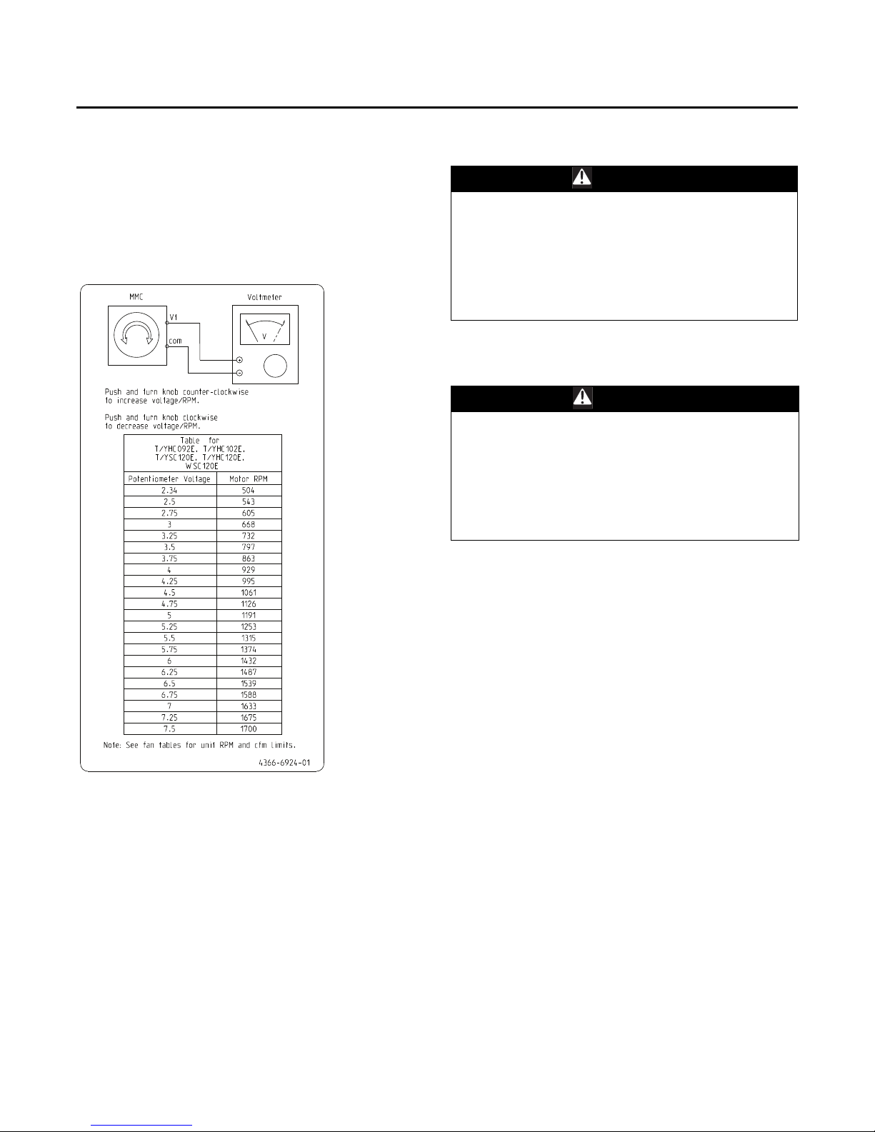
Sequence of Operation - Heat Pumps
table value), change indoor fan speed and repeat Step
1 and Step 2.
• Stop the SERVICE TEST, turn the main power
disconnect switch to the “Off” position and reconnect
Economizer 4-pin power connector if disconnected for
this procedure.
• Proceed to the next component start-up procedure.
Figure 57. Plenum fan rpm label
Economizer Start-Up
WARNING
Live Electrical Components!
Failure to follow all electrical safety precautions when
exposed to live electrical components could result in
death or serious injury. When necessary to work with
live electrical components, have a qualified licensed
electrician or other individual who has been properly
trained in handling live electrical components perform
these tasks.
Minimum Position Setting for 7.5 - 10 Ton with
Multi-Speed, or Single Zone VAV
WARNI NG
Live Electrical Components!
Failure to follow all electrical safety precautions when
exposed to live electrical components could result in
death or serious injury. When necessary to work with
live electrical components, have a qualified licensed
electrician or other individual who has been properly
trained in handling live electrical components perform
these tasks.
Return Air Smoke Detector
The return air smoke detector is designed to shut off the
unit if smoke is sensed in the return air stream. Sampling
the airflow entering the unit at the return air opening
performs this function.
In order for the smoke detector to properly sense smoke in
the return air stream, the air velocity entering the unit must
be between 500 and 4000 feet per minute. Equipment
covered in this manual will develop an airflow velocity that
falls within these limits over the entire airflow range
specified in the evaporator fan performance tables.
1. Apply power to the unit
2. Using the Service Test Guide on unit access panel,
momentarily jump across the Test 1 & Test 2 terminals
on LTB1 one time to start indoor fan.
3. Turn the MIN POS - DESIGN potentiometer on the
RTEM clockwise to open or counter-clockwise to close.
The damper will open to this setting for low speed fan
operation. When adjusting minimum position, the
damper may move to the new setting in several small
steps. Wait at least 15 seconds for the damper to settle
at the new position.
4. Momentarily jump across the Test 1 & Test 2 terminals
on LTB1, cycle through test modes to Cool 2 (2-Step
Cooling applications) or Cool 3 (3-Step Cooling
applications). Verify the indoor motor rpm is at 100% of
the user selected airflow.
5. Turn the MIN POS - DCV potentiometer on the RTEM
clockwise to open or counter-clockwise to close. This
will set the minimum damper position for high speed
fan operation.
6. The economizer minimum damper position for all fan
speeds is complete. The RTEM will control minimum
damper position along an imaginary line between the
damper minimum positions based on fan speed.
7. Replace the filter access panel. The damper will close
when the blower circuit is de-energized.
RT-SVX23M-EN 51
Page 52
Sequence of Operation - Heat Pumps
WARN ING
Live Electrical Components!
Failure to follow all electrical safety precautions when
exposed to live electrical components could result in
death or serious injury. When necessary to work with
live electrical components, have a qualified licensed
electrician or other individual who has been properly
trained in handling live electrical components perform
these tasks.
Using the Service Test Guide in Ta bl e 9 , p . 3 9 , momentarily
jump across the Test 1 & Test 2 terminals on LTB1 one time
to start the Minimum Ventilation Test.
1. Set the minimum position setpoint for the economizer
to the required percentage of minimum ventilation
using the setpoint potentiometer located on the
Economizer Control (ECA).
The economizer will drive to its minimum position
setpoint, exhaust fans (if applicable) may start at
random, and the supply fan will start when the
SERVICE TEST is initiated.
Compressor Start-Up
WARNI NG
Live Electrical Components!
Failure to follow all electrical safety precautions when
exposed to live electrical components could result in
death or serious injury. When necessary to work with
live electrical components, have a qualified licensed
electrician or other individual who has been properly
trained in handling live electrical components perform
these tasks.
Using the Service Test Guide in Table 9, p. 39, continue the
SERVICE TEST start-up procedure for each compressor
circuit.
1. Attach a set of service gauges onto the suction and
discharge gauge ports for each circuit. Refer to the
refrigerant circuit illustration in the Service Facts.
2. Momentarily jump across the Test 1 & Test 2 terminals
on LTB one additional time if continuing from previous
component start-up or until the desired start-up
component Test is started.
WARNI NG
Rotating Components!
Failure to follow all safety precautions below could
result in rotating components cutting and slashing
technician which could result in death or serious injury.
During installation, testing, servicing and
troubleshooting of this product it may be necessary to
work with live and exposed rotating components. Have
a qualified or licensed service individual who has been
properly trained in handling exposed rotating
components, perform these tasks.
The Exhaust Fan will start anytime the economizer
damper position is equal to or greater than the exhaust
fan setpoint.
2. Verify that the dampers stroked to the minimum
position.
3. Momentarily jump across the Test 1 & Test 2 terminals
on LTB1 one additional time if continuing from
previous component start-up or until the desired startup component Test is started.
4. Verify that the dampers stroked to the full open
position.
5. To stop the SERVICE TEST, turn the main power
disconnect switch to the “Off” position or proceed to
the next component start-up procedure.
Scroll Compressors
a. Once each compressor has started, verify that the
rotation is correct. If a scroll compressor is rotating
backwards, it will not pump and a loud rattling
sound can be observed.
b. If the electrical phasing is correct, before
condemning a compressor, interchange any two
leads (at the compressor Terminal block) to check
the internal phasing. If the compressor runs
backward for an extended period (15 to 30 minutes),
the motor winding can overheat and cause the
motor winding thermostat to open.
3. After the compressor and condenser fan have started
and operated for approximately 30 minutes, observe
the operating pressures. Compare the operating
pressures to the operating pressure curve in the
Service Facts.
4. Check system superheat. Follow the instruction listed
on the superheat charging curve in the Service Facts.
Superheat should be within ±5ºF of the superheat chart
value.
5. Repeat Step 1 through Step 4 for each refrigerant
circuit.
6. To stop the SERVICE TEST, turn the main power
disconnect switch to the “Off” position or proceed to
the next component start-up procedure.
52 RT-SVX23M-EN
Heating Start-Up
Using the Service Test Guide in Table 9, p. 39, continue the
SERVICE TEST start-up procedure for each compressor
circuit.
Page 53

1. Clamp an amp meter around one of 1st stage heater
power wires at the heater contactor.
2. Momentarily jump across the Test 1 & Test 2 terminals
on LTB one additional time if continuing from previous
component start-up or until the desired start-up
component Test is started.
3. Verify that the heater stage is operating properly.
nd
4. Clamp an amp meter around one of 2
power wires at the heater contactor (if applicable).
5. Momentarily jump across the Test 1 & Test 2 terminals
on LTB one additional time if continuing from previous
component start-up or until the desired start-up
component Test is started.
6. Verify that the heater stage is operating properly.
7. To stop the SERVICE TEST, turn the main power
disconnect switch to the “Off” position or proceed to
the next component start-up procedure.
stage heater
Final System Setup
After completing all of the pre-start and start-up
procedures outlined in the previous sections (i.e.,
operating the unit in each of its modes through all
available stages of cooling & heating), perform these final
checks before leaving the unit:
• Program the Night Setback (NSB) panel (if applicable)
for proper unoccupied operation. Refer to the
programming instructions for the specific panel.
• Verify that the Remote panel “System” selection
switch, “Fan” selection switch, and “Zone
Temperature” settings for automatic operation are
correct.
• Inspect the unit for misplaced tools, hardware, and
debris.
• Verify that all exterior panels including the control
panel doors and condenser grilles are secured in place.
• Close the main disconnect switch or circuit protector
switch that provides the supply power to the unit’s
terminal block or the unit mounted disconnect switch.
Make sure all personnel are standing clear of the unit
before proceeding. The system components will start
when the power is applied.
Sequence of Operation - Heat Pumps
RT-SVX23M-EN 53
Page 54
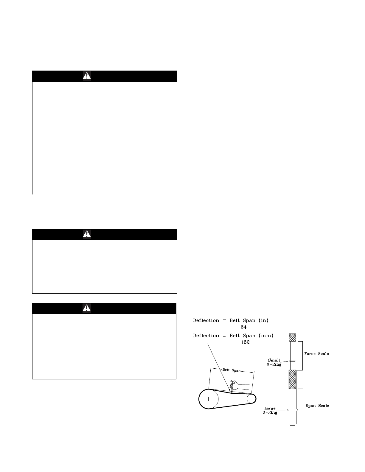
Maintenance
WARN ING
Hazardous Service Procedures!
Failure to follow all precautions in this manual and on
the tags, stickers, and labels could result in death or
serious injury.
Technicians, in order to protect themselves from
potential electrical, mechanical, and chemical hazards,
MUST follow precautions in this manual and on the
tags, stickers, and labels, as well as the following
instructions: Unless specified otherwise, disconnect all
electrical power including remote disconnect and
discharge all energy storing devices such as capacitors
before servicing. Follow proper lockout/tagout
procedures to ensure the power can not be
inadvertently energized. When necessary to work with
live electrical components, have a qualified licensed
electrician or other individual who has been trained in
handling live electrical components perform these
tasks.
Fan Belt Adjustment - Belt Drive
Units
WARN ING
Live Electrical Components!
Failure to follow all electrical safety precautions when
exposed to live electrical components could result in
death or serious injury. When necessary to work with
live electrical components, have a qualified licensed
electrician or other individual who has been properly
trained in handling live electrical components perform
these tasks.
Once the new belts are installed, using a Browning or
Gates tension gauge (or equivalent) illustrated in
Figure 58, p. 54; adjust the belt tension as follows;
1. To determine the appropriate belt deflection;
a. Measure the center-to-center shaft distance (in
inches) between the fan and motor sheaves.
b. Divide the distance measured in Step a by 64; the
resulting value represents the amount of belt
deflection that corresponds to the proper belt
tension.
2. Set the large O-ring on the belt tension gauge at the
deflection value determined in Step b.
3. Set the small O-ring at zero on the force scale of the
gauge plunger.
4. Place the large end of the gauge at the center of the belt
span; then depress the gauge plunger until the large Oring is even with the top of the next belt or even with
a straightedge placed across the fan and motor
sheaves. Refer to the figure below.
5. Remove the belt tension gauge. The small O-ring now
indicates a number other than zero on the plunger’s
force scale. This number represents the force (in
pounds) required to give the needed deflection.
6. Compare the “force” scale reading (Step 5) with the
appropriate “force” value listed in Tab le 1 8. If the
“force” reading is outside the range, readjust the belt
tension.
Note: Actual belt deflection “force” must not exceed the
maximum “force” value shown in Ta bl e 1 8 .
7. Recheck the belt tension at least twice during the first
2 to 3 days of operation. Belt tension may decrease
until the new belts are “run in”.
WARNI NG
Rotating Components!
Failure to follow all safety precautions below could
result in rotating components cutting and slashing
technician which could result in death or serious injury.
During installation, testing, servicing and
troubleshooting of this product it may be necessary to
work with live and exposed rotating components. Have
a qualified or licensed service individual who has been
properly trained in handling exposed rotating
components, perform these tasks.
The fan belts must be inspected periodically to assure
proper unit operation.
Replacement is necessary if the belts appear frayed or
worn. Units with dual belts require a matched set of belts
to ensure equal belt length.
When removing or installing the new belts, do not stretch
them over the sheaves. Loosen the belts using the belt
tension adjustment bolts on the motor mounting base.
54 RT-SVX23M-EN
Figure 58. Belt tension gauge
Page 55
Maintenance
Table 18. Belt tension measurement and deflection
ranges
Deflection Force (Lbs.)
Belts
Cross
Section
A
B
Super
Small P.D
Range
3.0 - 3.6 3 4 1/2 3 7/8 5 1/2 3 1/4 4
3.8 - 4.8 3 1/2 5 4 1/2 6 1/4 3 3/4 4 3/4
5.0 - 7.0 4 5 1/2 5 6 7/8 4 1/4 5 1/4
3.4 - 4.2 4 5 1/2 5 3/4 8 4 1/2 5 1/2
4.4 - 5.6 5 1/8 7 1/8 6 1/2 9 1/8 5 3/4 7 1/4
5.8 - 8.8 6 3/8 8 3/4 7 3/8 10 1/8 7 8 3/4
Gripbelts Gripnotch
Min. Max. Min. Max. Min. Max
Steel Cable
Gripbelts
Monthly Maintenance
WARNI NG
Hazardous Voltage!
Failure to disconnect power before servicing could
result in death or serious injury. Disconnect all electric
power, including remote disconnects before servicing.
Follow proper lockout/tagout procedures to ensure the
power can not be inadvertently energized.
Filters
Inspect the return air filters. Clean or replace them if
necessary. If included, leave filter removal tool in unit.
Refer to the unit Service Facts for filter information.
Return Air Smoke Detector Maintenance
Airflow through the unit is affected by the amount of dirt
and debris accumulated on the indoor coil and filters. To
insure that airflow through the unit is adequate for proper
sampling by the return air smoke detector, complete
adherence to the maintenance procedures, including
recommended intervals between filter changes, and coil
cleaning is required.
Periodic checks and maintenance procedures must be
performed on the smoke detector to insure that it will
function properly. For detailed instructions concerning
these checks and procedures, refer to the appropriate
section(s) of the smoke detector Installation and
Maintenance Instructions provided with the literature
package for this unit.
Condensate Overflow Switch
During maintenance, the switch float (black ring) must be
checked to ensure free movement up and down.
Cooling Season
• Check the unit’s drain pans and condensate piping to
ensure that there are no blockages.
• Inspect the evaporator and condenser coils for dirt,
bent fins, etc. If the coils appear dirty, clean them
according to the instructions described in “Coil
Cleaning” later in this section.
• Manually rotate the condenser fan(s) to ensure free
movement and check motor bearings for wear. Verify
that all of the fan mounting hardware is tight.
• Inspect the F/A-R/A damper hinges and pins to ensure
that all moving parts are securely mounted. Keep the
blades clean as necessary.
• Verify that all damper linkages move freely; lubricate
with white grease, if necessary.
• Check supply fan motor bearings; repair or replace the
motor as necessary.
• Check the fan shaft bearings for wear. Replace the
bearings as necessary.
• Check the supply fan belt. If the belt is frayed or worn,
replace it. Refer to the “Fan Belt Adjustment” section
for belt replacement and adjustments.
• Verify that all wire terminal connections are tight.
• Remove any corrosion present on the exterior surfaces
of the unit and repaint these areas.
• Generally inspect the unit for unusual conditions (e.g.,
loose access panels, leaking piping connections, etc.).
• Make sure that all retaining screws are reinstalled in
the unit access panels once these checks are complete.
• With the unit running, check and record the: ambient
temperature; compressor suction and discharge
pressures (each circuit); superheat (each circuit);
Record this data on an “operator’s maintenance log” like
the one shown in Ta bl e 19 , p . 5 7 . If the operating pressures
indicate a refrigerant shortage, measure the system
superheat. For guidelines, refer to the “Compressor StartUp” section.
Important: Do not release refrigerant to the
atmosphere! If adding or removing
refrigerant is required, the service
technician must comply with all federal,
state and local laws.
Heating Season
• Inspect the unit’s air filters. If necessary, clean or
replace them.
• Check supply fan motor bearings; repair or replace the
motor as necessary.
• Inspect both the main unit control panel and heat
section control box for loose electrical components
and terminal connections, as well as damaged wire
insulation. Make any necessary repairs.
• If the unit is equipped with electric heat, verify that the
electric heat system operates properly.
• If unit is equipped with gas heat, clean burner area and
verify gas heat system operation.
RT-SVX23M-EN 55
Page 56
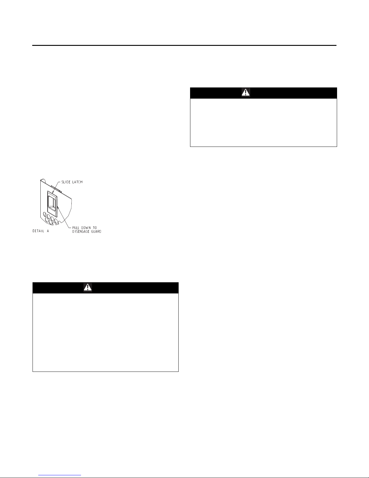
Maintenance
Coil Cleaning
Regular coil maintenance, including annual cleaning,
enhances the unit’s operating efficiency by minimizing:
compressor head pressure and amperage draw;
evaporator water carryover; fan brake horsepower, due to
increase static pressure losses; airflow reduction.
At least once each year, or more often if the unit is located
in a “dirty” environment, clean the evaporator and
condenser coils using the instructions outlined below. Be
sure to follow these instructions as closely as possible to
avoid damaging the coils.
Note: For units equipped with hail guards follow removal
procedure.
Hail Guard Removal
Figure 59. Slide-style
• Unlatch hail guards.
• Pull the top of the hail guard outward until the fastener
studs are free of the retaining nuts.
• Lift the hail guard from the lower retaining bracket and
set aside.
WARNING
Hazardous Chemicals!
Failure to follow all safety instructions below could
result in death or serious injury. Coil cleaning agents
can be either acidic or highly alkaline and can burn
severely if contact with skin occurs. Handle chemical
carefully and avoid contact with skin. ALWAYS wear
Personal Protective Equipment (PPE) including goggles
or face shield, chemical resistant gloves, boots, apron
or suit as required. For personal safety refer to the
cleaning agent manufacturer’s Materials Safety Data
Sheet and follow all recommended safe handling
practices.
To clean refrigerant coils, use a soft brush and a sprayer
(either a garden pump-up type or a high-pressure sprayer).
A high-quality detergent is also required; suggested
brands include “SPREX A.C.”, “OAKITE 161”, “OAKITE 166”
and “COILOX”. If the detergent selected is strongly alkaline
(ph value exceeds 8.5), add an inhibitor.
1. Remove enough panels from the unit to gain access to
the coil.
2. Protect all electrical devices such as motors and
controllers from any over spray.
3. Straighten any bent coil fins with a fin comb.
Mix the detergent with water according to the
manufacturer’s instructions. If desired, heat the solution to
150°F maximum to improve its cleansing capability.
WARNI NG
Hazardous Pressures!
Failure to follow safety precautions below could result
in coil bursting, which could result in death or serious
injury. Coils contain refrigerant under pressure. When
cleaning coils, maintain coil cleaning solution
temperature under 150°F to avoid excessive pressure in
the coil.
Note: Do not heat the detergent-and-water solution
above 150°F. Hot liquids sprayed on the exterior of
the coil will raise the coil’s internal pressure and
may cause it to burst. Failure to follow proper
procedures can result in personal illness or injury
or severe equipment damage.
1. Pour the cleaning solution into the sprayer. If a highpressure sprayer is used:
a. do not allow sprayer pressure to exceed 600 psi.
b. the minimum nozzle spray angle is 15 degrees.
c. maintain a minimum clearance of 6" between the
sprayer nozzle and the coil.
d. spray the solution perpendicular (at 90 degrees) to
the coil face.
2. Spray the leaving-airflow side of the coil first; then
spray the opposite side of the coil. Allow the cleaning
solution to stand on the coil for five minutes.
3. Rinse both sides of the coil with cool, clean water.
4. Inspect both sides of the coil; if it still appears to be
dirty, repeat Step 2 and Step 3.
5. Reinstall all of the components and panels removed in
Step 1 and any protective covers installed in Step 2.
Note: For units equipped with hail guards follow
reinstallation procedure listed below.
Hail Guard Reinstallation
To reinstall the hail guard, locate the bottom of the hail
guard in the lower bracket and secure it to the upper unit
bracket with the attached fasteners.
Note: Secure hail guard latches.
6. Restore the unit to its operational status and check
system operation.
56 RT-SVX23M-EN
Page 57
Maintenance
Final Process
For future reference, you may find it helpful to record the
unit data requested below in the blanks provided.
Complete Model Number
_____________________________________________________
Unit Serial Number
_____________________________________________________
Table 19. Sample maintenance log
Refrigerant Circuit #1 Refrigerant Circuit #2
Date
Current
Ambient
Temp. F/C
Compr.
Oil Level
- ok
- low
- ok
- low
- ok
- low
- ok
- low
- ok
- low
- ok
- low
- ok
- low
- ok
- low
- ok
- low
- ok
- low
- ok
- low
Suct.
Press.
Psig/
kPa
Disch.
Press.
Psig/
kPa
Liquid
Press.
Psig/
kPa
Super
-heat
F/C
Wiring Diagram Numbers (from unit control panel)
_____________________________________________________
Schematics
_____________________________________________________
Connections
_____________________________________________________
Subcool.
F/C
Compr.
Oil
Level
- ok
- low
- ok
- low
- ok
- low
- ok
- low
- ok
- low
- ok
- low
- ok
- low
- ok
- low
- ok
- low
- ok
- low
- ok
- low
Suct.
Press.
Psig/kPa
Disch.
Press.
Psig/
kPa
Liquid
Press.
Psig/
kPa
Superheat
F/C
Subcool.
F/C
RT-SVX23M-EN 57
Page 58
Troubleshooting
WARN ING
Hazardous Service Procedures!
Failure to follow all precautions in this manual and on
the tags, stickers, and labels could result in death or
serious injury.
Technicians, in order to protect themselves from
potential electrical, mechanical, and chemical hazards,
MUST follow precautions in this manual and on the
tags, stickers, and labels, as well as the following
instructions: Unless specified otherwise, disconnect all
electrical power including remote disconnect and
discharge all energy storing devices such as capacitors
before servicing. Follow proper lockout/tagout
procedures to ensure the power can not be
inadvertently energized. When necessary to work with
live electrical components, have a qualified licensed
electrician or other individual who has been trained in
handling live electrical components perform these
tasks.
ReliaTel™ Control
The RTRM has the ability to provide the service personnel
with some unit diagnostics and system status information.
Before turning the main power disconnect switch “Off”,
follow the steps below to check the ReliaTel Refrigeration
Module (RTRM). All diagnostics & system status
information stored in the RTRM will be lost when the main
power is turned “Off”.
4. If a System failure is indicated, recheck Step 1 and Step
2. If the LED is not lit in Step 1, and 24 VAC is present
in Step 2, the RTRM has failed. Replace the RTRM.
5. If no failures are indicated, use one of the TEST mode
procedures described in the “Unit Start-Up” section to
start the unit. This procedure will allow you to check all
of the RTRM outputs, and all of the external controls
(relays, contactors, etc.) that the RTRM outputs
energize, for each respective mode. Proceed to Step 6.
6. Step the system through all of the available modes,
and verify operation of all outputs, controls, and
modes. If a problem in operation is noted in any mode,
you may leave the system in that mode for up to one
hour while troubleshooting. Refer to the sequence of
operations for each mode, to assist in verifying proper
operation. Make the necessary repairs and proceed to
Step 7 and Step 8.
7. If no abnormal operating conditions appear in the test
mode, exit the test mode by turning the power “Off” at
the main power disconnect switch.
8. Refer to the individual component test procedures if
other microelectronic components are suspect.
System Status Checkout
Procedure
“System Status” is checked by using one of the following
two methods:
WARNING
Live Electrical Components!
Failure to follow all electrical safety precautions when
exposed to live electrical components could result in
death or serious injury. When necessary to work with
live electrical components, have a qualified licensed
electrician or other individual who has been properly
trained in handling live electrical components perform
these tasks.
1. Verify that the Liteport LED on the RTRM is burning
continuously. If the LED is lit, go to Step 3.
2. If the LED is not lit, verify that 24 VAC is presence
between J1-1 and J1-2. If 24 VAC is present, proceed to
Step 3. If 24 VAC is not present, check the unit main
power supply, check transformer (TNS1). Proceed to
Step 3 if necessary.
3. Utilizing “Method 1” or “Method 2” in the “System
Status Diagnostic” section, check the following:
• System status
• Heating status
• Cooling status
If a System failure is indicated, proceed to Step 4. If no
failures are indicated, proceed to Step 5.
Method 1
If the Zone Sensor Module (ZSM) is equipped with a
remote panel with LED status indication, you can check the
unit within the space. If the ZSM does not have LED’s, use
Method 2. BAYSENS110*, BAYSENS109*, BAYSENS119*,
& BAYSENS023A all have the remote panel indication
feature. The LED descriptions are listed below.
Zone Sensor LED 1 (System)
“On” during normal operation.
“Off” if a system failure occurs or the LED fails.
“Flashing” indicates test mode.
Zone Sensor LED 2 (Heat)
“On” when the heat cycle is operating.
“Off” when the heat cycle terminates or the LED fails.
“Flashing” indicates a heating failure.
Zone Sensor LED 3 (Cool)
“On” when the cooling cycle is operating.
“Off” when the cooling cycle terminates or the LED fails.
“Flashing” indicates a cooling failure.
58 RT-SVX23M-EN
Page 59

Troubleshooting
Zone Sensor LED 4 (Service)
“On” indicates a clogged filter.
“Off” during normal operation.
“Flashing” indicates an evaporator or condensate
overflow switch failure.
Below is the complete listing of failure indication causes.
System Failure
Check the voltage between terminals 6 and 9 on J6, it
should read approximately 32 VDC. If no voltage is
present, a system failure has occurred. Refer to Step 4 in
the previous section for the recommended
troubleshooting procedure.
Cooling Failure
• Cooling and heating set point (slide pot) on the zone
sensor has failed. Refer to the “Zone Sensor Test
Procedure” section.
• Zone temperature thermistor ZTEMP on ZTS failed.
Refer to the “Zone Sensor Test Procedure” section.
• CC1 or CC2 24 VAC control circuit has opened, check
CC1 & CC2 coils, and any of the controls below that
apply to the unit (HPC1, HPC2).
• LPC1 has opened during the 3 minute minimum “on
time” during 4 consecutive compressor starts, check
LPC1 or LPC2 by testing voltage between the J1-8 & J32 terminals on the RTRM and ground. If 24 VAC is
present, the LPC’s has not tripped. If no voltage is
present, LPC’s has tripped.
Service Failure
• If the supply fan proving switch has closed, the unit will
not operate (when connected to RTOM), check the fan
motor, belts, and proving switch.
• Clogged filter switch has closed, check the filters.
• If the condensate overflow switch is closed, the unit
will not operate, check the float position is not in a
tripped condition and verify an "open" between wires
connecting to RTOM J6-1, J6-2.
Simultaneous Heat and Cool Failure
• Emergency Stop is activated.
Method 2
The second method for determining system status is done
by checking voltage readings at the RTRM (J6). The system
indication descriptions and the approximate voltages are
listed below.
Test Mode = voltage alternates between 32 VDC & 0.75
VDC
Heat Failure
Measure the voltage between terminals J6-7 & J6-6.
Heat Operating = approximately 32 VDC
Heat Off = less than 1 VDC, approximately 0.75 VDC
Heating Failure = voltage alternates between 32 VDC &
0.75 VDC
Cool Failure
Measure the voltage between terminals J6-8 & J6-6.
Cool Operating = approximately 32 VDC
Cool Off = less than 1 VDC, approximately 0.75 VDC
Cooling Failure = voltage alternates between 32 VDC &
0.75 VDC
Service Failure
Measure the voltage between terminals J6-10 & J6-6.
Clogged Filter = Approximately 32 VDC.
Normal = Less than 1 VDC, approximately 0.75 VDC Fan
Failure = voltage alternates between 32 VDC & 0.75 VDC.
To use LED’s for quick status information at the unit,
purchase a BAYSENS110* ZSM and connect wires with
alligator clamps to terminals 6 through 10. Connected each
respective terminal wire (6 through 10) from the Zone
Sensor to the unit J6 terminals 6 through 10.
Note: If the system is equipped with a programmable
zone sensor, BAYSENS119* the LED indicators will
not function while the BAYSENS110* is connected.
Resetting Cooling and Heating Lockouts
Cooling Failures and Heating Lockouts are reset in an
identical manner. Method 1 explains resetting the system
from the space; Method 2 explains resetting the system at
the unit.
Note: Before resetting Cooling Failures and Heating
Lockouts check the Failure Status Diagnostics by
the methods previously explained. Diagnostics will
be lost when the power to the unit is disconnected.
Method 1
To reset the system from the space, turn the “Mode”
selection switch at the zone sensor to the “Off” position.
After approximately 30 seconds, turn the “Mode”
selection switch to the desired mode, i.e. Heat, Cool or
Auto.
System Failure
Measure the voltage between terminals J6-9 & J6-6.
Normal Operation = approximately 32 VDC
System Failure = less than 1 VDC, approximately 0.75 VDC
RT-SVX23M-EN 59
Method 2
To reset the system at the unit, cycle the unit power by
turning the disconnect switch “Off” and then “On”.
Lockouts can be cleared through the building
management system. Refer to the building management
system instructions for more information.
Page 60
Troubleshooting
Zone Temperature Sensor (ZTS)
Service Indicator
The ZSM SERVICE LED is a generic indicator, that will
signal the closing of a Normally Open switch at any time,
providing the Indoor Motor (IDM) is operating. This
indicator is usually used to indicate a clogged filter, or an
air side fan failure.
The RTRM will ignore the closing of this Normally Open
switch for 2 (±1) minutes. This helps prevent nuisance
SERVICE LED indications. The exception is the LED will
flash 40 seconds after the fan is turned “On” if the Fan
Proving Switch is not made.
Clogged Filter Switch
This LED will remain lit the entire time that the Normally
Open switch is closed. The LED will be turned off
immediately after resetting the switch (to the Normally
Open position), or any time that the IDM is turned “Off”.
If the switch remains closed, and the IDM is turned “On”,
the SERVICE LED will be turned “On” again after the 2 (±1)
minute ignore delay.
This LED being turned “On”, will have no other affect on
unit operation. It is an indicator only.
Fan Failure Switch
When the “Fan Failure” switch is wired to the RTOM, the
LED will remain flashing the entire time the fan proving
switch is closed, indicating a fan failure, and it will shut the
unit operations down.
Condensate Overflow Switch
When the “Condensate Overflow Switch" is closed, a drain
pan overflow condition is indicated and it will shut unit
operations down.
Zone Temperature Sensor (ZTS)
Test
Note: These procedures are not for programmable or
digital models and are conducted with the Zone
Sensor Module electrically removed from the
system.
Test 1 Zone Temperature Thermistor
(ZTEMP)
This component is tested by measuring the resistance
between terminals 1 and 2 on the Zone Temperature
Sensor. Below are some typical indoor temperatures, and
corresponding resistive values.
Test 2 Cooling Set Point (CSP) and Heating
Set Point (HSP)
Table 20. Cooling (CSP) and heating setpoint (HSP)
Zone
Temperature
50°F 10.0 C° 19.9 K-Ohms 889 Ohms
55°F 12.8 C° 17.47 K-Ohms 812 Ohms
60°F 15.6 C° 15.3 K-Ohms 695 Ohms
65°F 18.3 C° 13.49 K-Ohms 597 Ohms
70°F 21.1 C° 11.9 K-Ohms 500 Ohms
75°F 23.9 C° 10.50 K-Ohms 403 Ohms
80°F 26.7 C° 9.3 K-Ohms 305 Ohms
85°F 29.4 C° 8.25 K-Ohms 208 Ohms
90°F 32.2 C° 7.3 K-Ohms 110 Ohms
The resistance of these potentiometers are measured
between the following ZSM terminals. Refer to the chart
above for approximate resistances at the given setpoints.
Cool SP = Terminals 2 and 3
Range = 100 to 900 Ohms approximate
Heat SP = Terminals 2 and 5
Range = 100 to 900 Ohms approximate
Nominal ZTEMP
Resistance
Nominal CSP or
HSP Resistance
Test 3 System Mode and Fan Selection
The combined resistance of the Mode selection switch and
the Fan selection switch can be measured between
terminals 2 and 4 on the Zone Sensor. The possible switch
combinations are listed below with their corresponding
resistance values.
Test 4 LED Indicator Test, (SYS ON, HEAT,
COOL & SERVICE)
Method 1
Testing the LED using a meter with diode test function. Test
both forward and reverse bias. Forward bias should
measure a voltage drop of 1.5 to 2.5 volts, depending on
your meter. Reverse bias will show an Over Load, or open
circuit indication if LED is functional.
Method 2
Testing the LED with an analog Ohmmeter. Connect
Ohmmeter across LED in one direction, then reverse the
leads for the opposite direction. The LED should have at
least 100 times more resistance in reverse direction, as
compared with the forward direction. If high resistance in
both directions, LED is open. If low in both directions, LED
is shorted.
Method 3
To test LED’s with ZSM connected to unit, test voltages at
LED terminals on ZSM. A measurement of 32 VDC, across
an unlit LED, means the LED has failed.
Note: Measurements should be made from LED common
(ZSM terminal 6 to respective LED terminal). Refer
to the Zone Sensor Module (ZSM) Terminal
Identification table at the beginning of this section.
60 RT-SVX23M-EN
Page 61
Troubleshooting
Programmable & Digital Zone
Sensor Test
Testing Serial Communication Voltage
WARNING
Live Electrical Components!
Failure to follow all electrical safety precautions when
exposed to live electrical components could result in
death or serious injury. When necessary to work with
live electrical components, have a qualified licensed
electrician or other individual who has been properly
trained in handling live electrical components perform
these tasks.
1. Verify 24 VAC is present between terminals J6-14 & J6-
11.
2. Disconnect wires from J6-11 and J6-12. Measure the
voltage between J6-11 and J6-12, should be about 32
VDC.
3. Reconnect wires to terminals J6-11 and J6-12. Measure
voltage again between J6-11 and J6-12, voltage should
flash high and low every 0.5 seconds. The voltage on
the low end will measure about 19 VDC, while the
voltage on the high end will measure from
approximately 24 to 38 VDC.
4. Verify all modes of operation, by running the unit
through all of the steps in the “Test Modes” section
discussed in “Unit Start-Up”.
5. After verifying proper unit operation, exit the test
mode. Turn the fan on continuously at the ZSM, by
pressing the button with the fan symbol. If the fan
comes on and runs continuously, the ZSM is good. If
you are not able to turn the fan on, the ZSM is
defective.
Unit Operation without a Zone Sensor
This procedure is for temporary operation only. The
economizer and condenser fan cycling functions are
disabled.
WARNING
Hazardous Voltage!
Failure to disconnect power before servicing could
result in death or serious injury. Disconnect all electric
power, including remote disconnects before servicing.
Follow proper lockout/tagout procedures to ensure the
power can not be inadvertently energized.
1. Open and Lock the unit disconnect switch.
2. Remove the Outside Air Sensor (OAS) from the
condenser section of unit.
3. Use two (2) wire nuts, to individually cap the wires.
4. Locate the RTRM (J6). Connect two (2) wires to
terminals J6-1 and 2.
5. Connect the sensor (OAS) using two wire nuts to the
two (2) field supplied wires that were connected to
terminals 1 and 2 on J6.
ReliaTel™ Refrigeration Module (RTRM)
Default Chart
If the RTCI loses input from the building management
system, the RTRM will control in the default mode after
approximately 15 minutes. If the RTRM loses the Heating
and Cooling setpoint input, the RTRM will control in the
default mode instantaneously. The temperature sensing
thermistor in the Zone Sensor Module is the only
component required for the “Default Mode” to operate.
RT-SVX23M-EN 61
Page 62
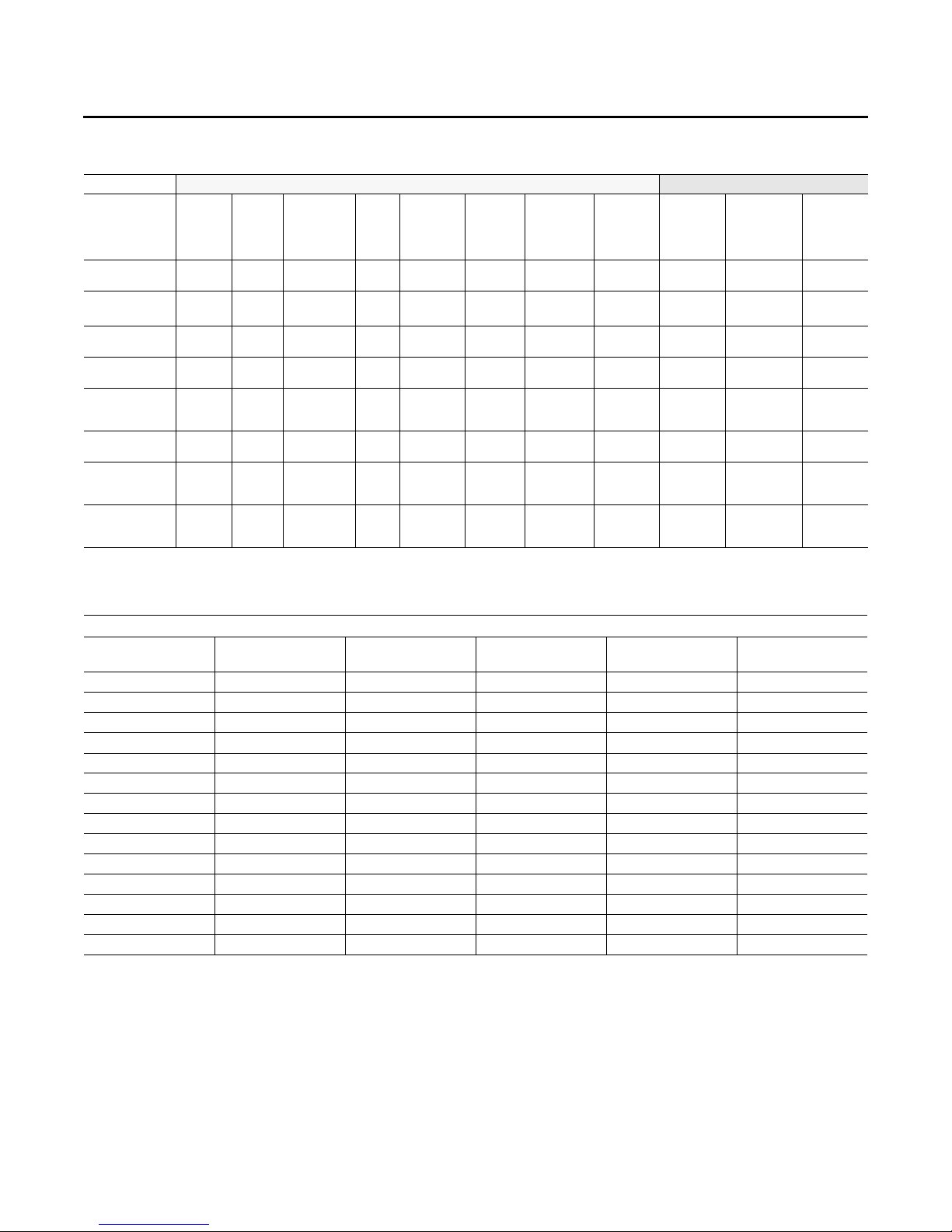
Troubleshooting
Table 21. Fault detection and diagnostic codes
Primary Fault Codes Information Code
Mixed Air
Failures
Damper stuck
at Minimum
Damper Stuck
Open
Mixed Sensor
Failure
Supply Air
Sensor Failure
Outdoor Air
Temperature
Fail
Power loss to
RTEM
Failed or Power
Loss to
Actuator
Mechanical
Failure of
Actuator
(a) If goes out of range.
Sensor
Temp
Fail
Outdoor
Sensor
Temp
Fail
Economizer
Actuator
Fault
RTEM
Comm
Fail
XX
XX(a) X(a) X(a) XX
X X
X X
X
X X
Pressure
Dead band
Fail
(If Used)
(a)
Temp
Sensor
Fail
(If Used)
Airflow
Sensor Fail
(If Used)
Space
Press Dead
band Fail
(If Used)
Unit Fails
to
Economize
Unit
Economizing
When It
Should Not
Damper
Position %
Indicated
X(a)*X(a) XX
XX
X
Table 22. Low leak economizer sensor values
Temp °F
40 26.097 54 17.847 68 12.435
41 25.383 55 17.382 69 12.126
42 24.690 56 16.930 70 11.827
43 24.018 57 16.491 71 11.535
44 23.367 58 16.066 72 11.252
45 22.736 59 15.654 73 10.977
46 22.132 60 15.253 74 10.709
47 21.530 61 14.864 75 10.448
48 20.953 62 14.486 76 10.194
49 20.396 63 14.119 77 9.949
50 19.854 64 13.762 78 9.710
51 19.330 65 13.416 79 9.477
52 18.821 66 13.078 80 9.250
53 18.327 67 12.752 81 9.030
Resistance
(K ohms) Temp °F
Sensor Values Data
Resistance
(K ohms) Temp °F
Resistance
(K ohms)
62 RT-SVX23M-EN
Page 63

Troubleshooting
Unit Economizer Control (ECA)
Troubleshooting ReliaTel Control
Verify Economizer Status by Economizer Actuator (ECA)
LED indicator:
OFF: No Power or Failure
ON: Normal, OK to Economize
Slow Flash: Normal, not OK to Economize
Fast Flash - 1/2 Second On / 2 Seconds Off:
Error Code:
Communications Failure
Pulse Flash: 2 Seconds On / 1/2 Second Off:
Error Code:
1 Flash: Actuator Fault
2 Flashes:CO2 Sensor
3 Flashes: RA Humidity Sensor
4 Flashes: RA Temp Sensor
5 Flashes: OA Quality Sensor
6 Flashes: OA Humidity Sensor
7 Flashes: OA Temp Sensor
8 Flashes: MA Temp Sensor
9 Flashes: RAM Fault
10 Flashes: ROM Fault
11 Flashes: EEPROM F
Refer to RT-SVB90*-EN for a comprehensive
troubleshooting guide.
Mixed Air Temperature Low Limit
Diagnostic
In all conditions on all ReliaTel™ controlled units, if the
mixed air temperature falls below 45F, the mixed air
temperature low limit diagnostic is active and the
economizer actuator will close to the active minimum
position. On Title 24 compliant units, ReliaTel™ will set an
auto-reset diagnostic to be used by BAS and TD-5 when
the mixed air temperature low limit is active.
The RTEM will revert to normal operation when the mixed
air temperature rises above 48F. The diagnostic will be
reset when the mixed air temperature low limit is inactive.
Troubleshooting Procedures for
Direct Drive Plenum Fan
Prior to troubleshooting, verify all wiring and wiring
connections. The motor has internal protections that will
shut down the motor before damage occurs. A power
cycle is required to reset some of the internal protections.
Before proceeding, power down unit for 1 minute and then
power on.
Please follow steps sequentially unless directed differently
in solution.
RT-SVX23M-EN 63
Page 64
Wiring Diagrams
Note: Wiring diagrams can be accessed using e-Library
by entering the diagram number in the literature
order number search field or by contacting
technical support.
Table 23. Unit wiring diagram numbers
Schematic
Type Voltage Drawing Number Description
Control
Control
Control
Control
Control
Control 230,460,575
Control 230,460,575
Control 230,460,575
Control 230,460,575
Control 230,460,575
Control 230,460,575
Power and
Control
Power 230V
Power 230V
Power 460-575V
Power 460-575V
Power
Power 230,460,575
Power
Power
Connection
Connection
Connection
Connection
Connection
Connection
Connection Electric Heat
Connection Electric Heat
Connection Electric Heat
Connection Electric Heat
Connection Electric Heat
208-230,
460, 575
208-230,
460, 575
208-230,
460, 575
208-230,
460, 575
208-230,
460, 575
230-460
575
208-230,
460, 575
230,460,575
230,460,575
208-230,
460, 575
208-230,
460, 575
208-230,
460, 575
208-230,
460, 575
208-230,
460, 575
208-230,
460, 575
208-240V
208-240V
208-240V
208-240V
208-240V
4366-1007 6 to 7.5 Ton Heat Pump
4366-1043 10 Ton Heat Pump
1213-2085 3 to 5 Ton Standard Efficiency Heat Pump/Direct Drive Motor
1213-2086 3 to 5 Ton High Efficiency Duel Fuel/Direct Drive Motor
1213-2087 3 to 5 Ton High Efficiency Heat Pump/Direct Drive Motor
1213-2519 WSC072H
1213-2520 WSC(090-120)H
1213-2521 WHC(074-120)H
1213-2523 DHC(074-102)H
1213-2524 DHC120H
1213-2707 WHC120H
4366-7427 230-460v/60Hz/3Ph - 10 Ton Heat Pump
4366-7428 575v/60Hz/3Ph - 10 Ton Heat Pump
4366-1014 230v/60hz/3ph 6 to 7.5 Ton Heat Pump / Belt Drive Motor
4366-1036 230v/60hz/3ph 10 Ton Heat Pump / Belt Drive Motor
4366-1010 460-575v/60hz/3ph 2 to 7.5 Ton Heat Pump / Belt Drive Motor
4366-1035 460-575v/60hz/3ph 10 Ton Heat Pump / Belt Drive Motor
1213-2083 3 - 5 Ton Heat Pump/Direct Drive Motor
1213-2515 WSC(072-102)H CONSTANT VOLUME IDM
1213-2516
1213-2517
4366-1542 208-230,460,575v/60hz/3ph 6 - 7.5 Ton Heat Pump / Belt Drive
4366-1535 208-230,460,575v/60hz/3ph 10 Ton Heat Pump / Belt Drive
4366-7446 230-460v/60Hz/3Ph - 10 Ton Heat Pump
4366-7447 575v/60Hz/3Ph - 10 Ton Heat Pump
4366-1031 Through The Base Utilities Schematic
4366-1048 CO2/Ventilation Override Schematics
4366-1084 9.0 & 18.0 KW - 208-240v/60hz/3ph BAYHTRS309*, BAYHTRS318*
4366-1094 12.0 & 17.4 KW - 208-240v/60hz/3ph BAYHTRR312*, BAYHTRR318*
4366-1095 23.0 KW - 208-240v/60hz/3ph BAYHTRR323*
4366-1089 27.0 & 36.0 KW - 208-240v/60hz/3ph BAYHTRS327*, BAYHTRS336*
4366-1086 54.0 KW - 208-240v/60hz/3ph BAYHTRT354*
WSC(090-120)H, WHC(074-102)H, DHC(074-102)H, Multi-Speed IDM, SZVAV, MZVAV
IDM
DHC120H & WHC120H
64 RT-SVX23M-EN
Page 65
Table 23. Unit wiring diagram numbers (continued)
Schematic
Type Voltage Drawing Number Description
Connection Electric Heat
Connection Electric Heat
Connection Electric Heat
Connection Electric Heat
Connection Electric Heat
208-600V
208-600V
208-600V
208-600V
208-600V
Component
Location
208-600V
Diagram
Component
Location
208-600V
Diagram
Options 230,460,575
Options 230,460,575
Device
Location 230,460,575
Device
Location 230,460,575
Device
Location 230,460,575
Device
Location 230,460,575
4366-1096 6.0 KW - 208-600v/60hz/3ph BAYHTRR306*, BAYHTRR406*, BAYHTRRW06*
4366-1097
4366-1087
4366-1089
4366-1090 54.0 KW - 480-600v/60hz/3ph BAYHTRT454*, BAYHTRTW54*
1213-2090 F - Cabinet Heat Pump/Dual Fuel
1213-2091 C - Cabinet Heat Pump/Dual Fuel
1213-2667 Option - RTVM, D/E Cabinet
1213-2668 Option - MULTI-ZONE VAV, D/E Cabinet
1213-2698 WSC(072-102)H Reliatel, Belt Drive Indoor Fan, Heat Pump, C/D Cab, Device Location
1213-2699 WSC(090-120)H Reliatel, EBM Indoor Fan, Heat Pump,, C/D Cab Device Location
1213-2789
1213-2790
9.0 & 18 KW - 480-600v/60hz/3ph BAYHTRS409*, BAYHTRSW09*, BAYHTRS418*,
BAYHTRT418*, BAYHTRSW18*, BAYHTRTW18*
12.0, 17.4 & 23.0 KW - 480-600v/60hz/3ph BAYHTRR412*, BAYHTRR418*,
BAYHTRR423*, BAYHTRRW12*, BAYHTRRW18*, BAYHTRRW23*
27.0 & 36.0 KW - 480-600v/60hz/3ph BAYHTRS427*, BAYHTRT427*, BAYHTRSW27*,
BAYHTRTW27*, BAYHTRS436*, BAYHTRT436*, BAYHTRSW36*, BAYHTRTW36*
WHC(074-102) H Reliatel, EBM Indoor Fan, High Efficiency Heat Pump D Cab Device
Location
WHC120H & DHC120H Reliatel, EBM Indoor Fan, High Efficiency Heat Pump E Cab
Device Location
Wiring Diagrams
RT-SVX23M-EN 65
Page 66

Limited Warranty
Heat Pump WCD, WCH, WSC, WHC and
DHC (Parts Only)
Models Less Than 20 Tons for Commercial
Use*
This warranty is extended by Trane to the original
purchaser and to any succeeding owner of the real
property to which the Heat Pump is originally affixed, and
applies to products purchased and retained for use within
the U.S.A. and Canada. There is no warranty against
corrosion, erosion or deterioration.
If any part of your Heat Pump fails because of a
manufacturing defect within one year from the date of the
original purchase, Warrantor will furnish without charge
the required replacement part.
In addition, if the sealed motor-compressor fails because
of a manufacturing defect within the second through fifth
year from the date of original purchase, Warrantor will
furnish without charge the required replacement
compressor.
Warrantor’s obligations and liabilities under this warranty
are limited to furnishing F.O.B. Warrantor factory or
warehouse at Warrantor designated shipping point,
freight allowed to Buyer’s city, replacement parts for
Warrantor’s products covered under this warranty.
Warrantor shall not be obligated to pay for the cost of lost
refrigerant. No liability shall attach to Warrantor until
products have been paid for and then liability shall be
limited solely to the purchase price of the equipment
under warranty shown to be defective.
THE WARRANTY AND LIABILITY SET FORTH HEREIN ARE
IN LIEU OF ALL OTHER WARRANTIES AND LIABILITIES,
WHETHER IN CONTRACT OR IN NEGLIGENCE, EXPRESS
OR IMPLIED, IN LAW OR IN FACT, INCLUDING IMPLIED
WARRANTIES OF MERCHANTABILITY AND FITNESS FOR
PARTICULAR USE, AND IN NO EVENT SHALL
WARRANTOR BE LIABLE FOR ANY INCIDENTAL OR
CONSEQUENTIAL DAMAGES.
Some states do not allow limitations on how long an
implied warranty lasts or do not allow the exclusion or
limitation of incidental or consequential damages, so the
above limitation or exclusion may not apply to you. This
warranty gives you specific legal rights, and you may also
have other rights which vary from state to state.
Tra ne
2701 Wilma Rudolph Blvd.
Clarksville, TN 37040-1008
Attention: Manager, Product Service
GW-604-4800
* This warranty is for commercial usage of said equipment
and not applicable when the equipment is used for a
residential application. Commercial use is any application
where the end purchaser uses the product for other than
personal, family or household purposes.
**A 5 year limited warranty is provided for the optional
"Low Leak" economizer when combined with the
additional FDD (Fault Detection & Diagnostics) option.
66 RT-SVX23M-EN
Page 67

Page 68
Ingersoll Rand (NYSE:IR) advances the quality of life by creating comfortable, sustainable and efficient
ingersollrand.com
environments. Our people and our family of brands—including Club Car®, Ingersoll Rand®, Thermo King® and
Trane®—work together to enhance the quality and comfort of air in homes and buildings; transport and protect
food and perishables; and increase industrial productivity and efficiency. We are a global business committed to a
world of sustainable progress and enduring results.
Ingersoll Rand has a policy of continuous product and product data improvement and reserves the right to change design and specifications
without notice.
We are committed to using environmentally conscious print practices.
RT-SVX23M-EN 04 Apr 2018
Supersedes RT-SVX23L-EN (May 2017)
©2018 Ingersoll Rand
 Loading...