

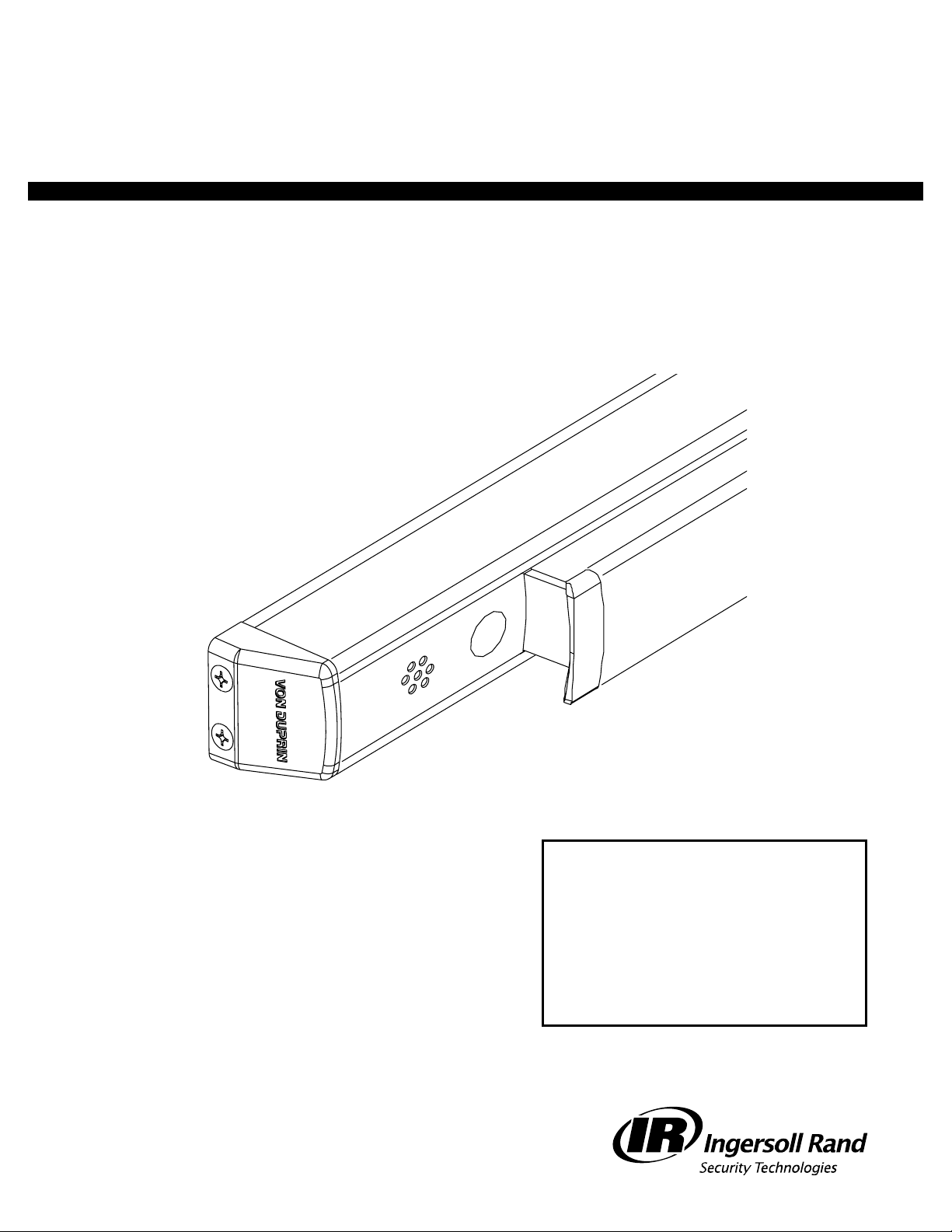
Ingersoll-Rand VON DUPRIN 33 Series, VON DUPRIN 98 Series, VON DUPRIN 35 Series, VON DUPRIN 99 Series Installation Instructions Manual
Page 1
VON DUPRIN
®
Installation Instructions
33/35 and 98/99 Series
ALK Alarm Kit
941042_00(4)
Index:
• General Information ...................... 2
• Parts List ............................................ 2
• Installation ....................................... 3
• Operating Instructions .................. 6
• Changing the Battery..................... 7
• EI (External Inhibit) Wiring ........... 8
© 2006 Ingersoll-Rand Company Limited
Page 2
GENERAL INFORMATION
These instructions are presented in step-by-step sequence.
Review this page carefully. It will help identify the hardware and define the terminology used throughout.
PARTS LIST
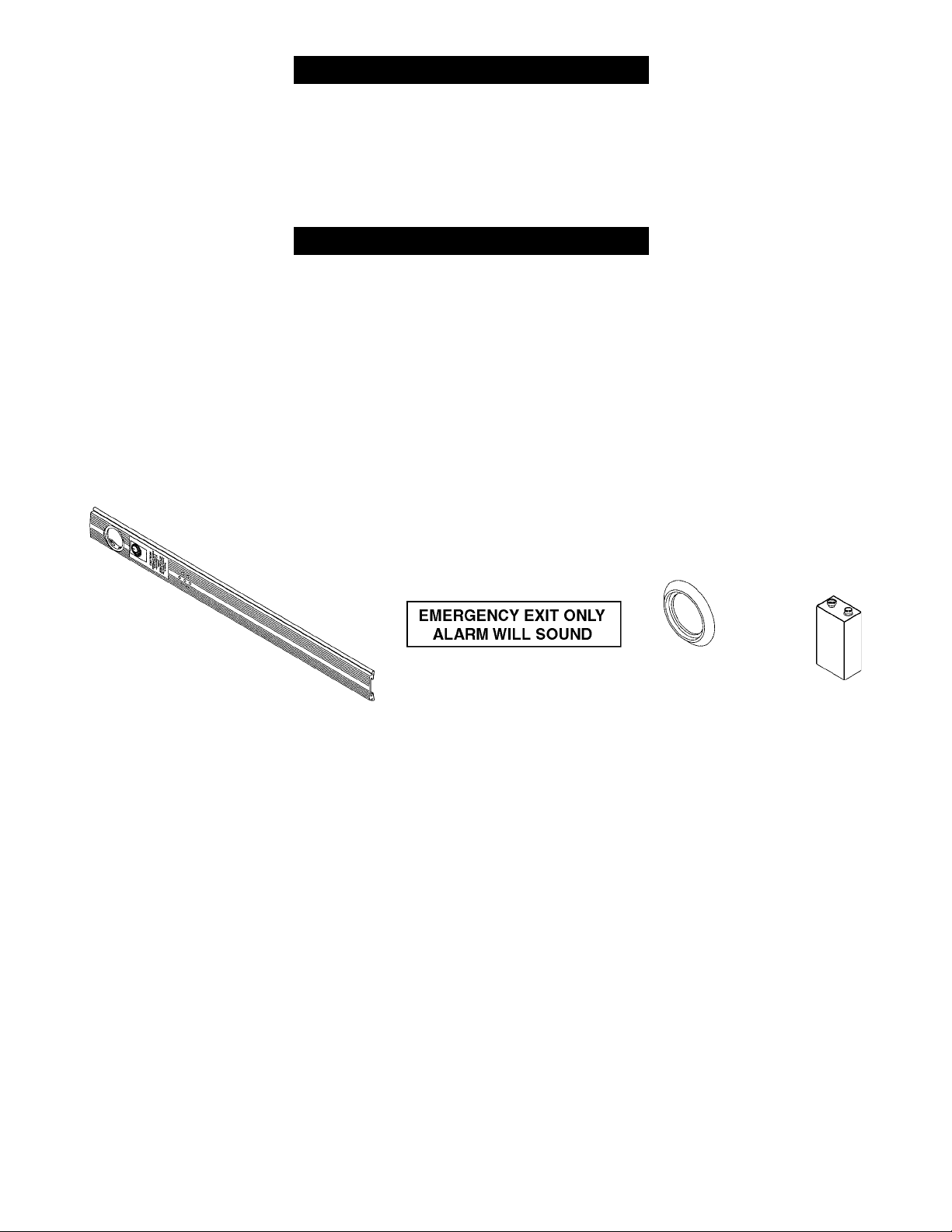
Note: The ALK Alarm Kit requires an RX or LX switch mounted in the exit device.
This kit includes the following parts (shown below):
• •
ALK Unit
•
• •
• •
• Emergency Exit Sign
• •
• •
• Cylinder Collar
• •
• •
• 9 Volt Battery
• •
Page 2 of 8Page 2 of 8
Page 2 of 8
Page 2 of 8Page 2 of 8
ALK Unit
(faceplate shown)
Emergency Exit Sign
(packed in cardboard tube)
Cylinder
Collar
9 Volt
Battery
941042_00(4)941042_00(4)
941042_00(4)
941042_00(4)941042_00(4)
Page 3
INSTALLATION
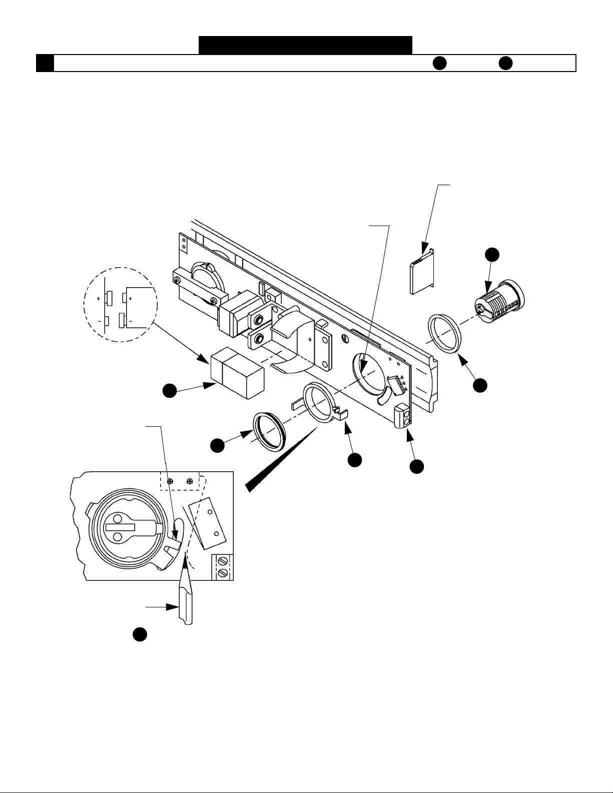
Assemble the ALK unit with the parts in order as shown below, through .
1
Make sure
polarity
is correct
Do not allow
pieces to slip out
A
Remove
and
discard
F
A Lock cylinder
9 volt battery F
Cam should be in
OFF position before
battery is installed
Push leaf spring
in this direction
to install item D
B Cylinder collar
E
D
C
941042_00(4)941042_00(4)
941042_00(4)
941042_00(4)941042_00(4)
Page 3 of 8Page 3 of 8
Page 3 of 8
Page 3 of 8Page 3 of 8
Page 4
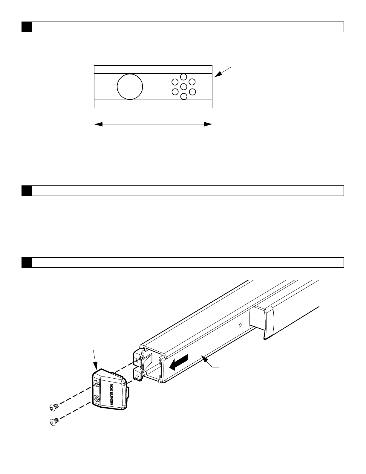
Cut the device and/or cover plate (end opposite cylinder hole) to proper length.
2
Note: See device installation instructions for additional information.
Cut this end
Minimum cover plate
length is 8-7/8”
If exit device does not have LX or RX switch in it, install switch before proceeding.
3
Note: Refer to the appropriate RX or LX installation instructions.
Remove the exit device end cap and dogging cover.
4
End cap
Dogging cover
Page 4 of 8Page 4 of 8
Page 4 of 8
Page 4 of 8Page 4 of 8
941042_00(4)941042_00(4)
941042_00(4)
941042_00(4)941042_00(4)
Page 5
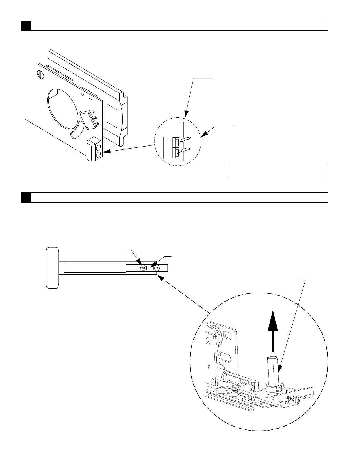
Attach switch wires to terminal block on ALK board as shown.
5
LX SWITCH WIRES
Use white and gray wires;
insulate violet wire
RX SWITCH WIRES
Use red and blue wires;
insulate yellow wire
Side view of board
Remove dogging shaft if present and slide ALK unit into device.
6
Note: Make sure that the wires do not tangle with moving parts by carefully pulling them toward the
dogging end of the device while sliding in the ALK unit.
ALK assembly
Remove label
Note: Wires are not polarized.
Remove dogging
shaft if present
941042_00(4)941042_00(4)
941042_00(4)
941042_00(4)941042_00(4)
Page 5 of 8Page 5 of 8
Page 5 of 8
Page 5 of 8Page 5 of 8
Page 6
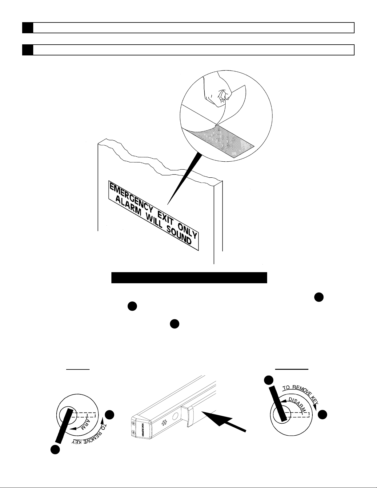
Install device to door.
7
Mount sign by peeling off protective backing and sticking sign into place.
8
OPERATING INSTRUCTIONS
1. Insert the key into the cylinder and arm the unit by turning the key clockwise to position B until it
stops. Return key to position A to remove. The unit will arm in 15 to 20 seconds.
2. Depress the pushbar after 20 seconds; the alarm should sound immediately.
3. Turn the key counterclockwise to position C to disarm.
Note: After the ALK alarm is on for approximately 6 minutes, it will begin to turn itself off and on every
10 seconds to conserve battery life.
TO ARM
RHR Shown
(LHR opposite)
A
Push to test
B
TO DISARM
C
A
RHR Shown
(LHR opposite)
Page 6 of 8Page 6 of 8
Page 6 of 8
Page 6 of 8Page 6 of 8
941042_00(4)941042_00(4)
941042_00(4)
941042_00(4)941042_00(4)
Page 7
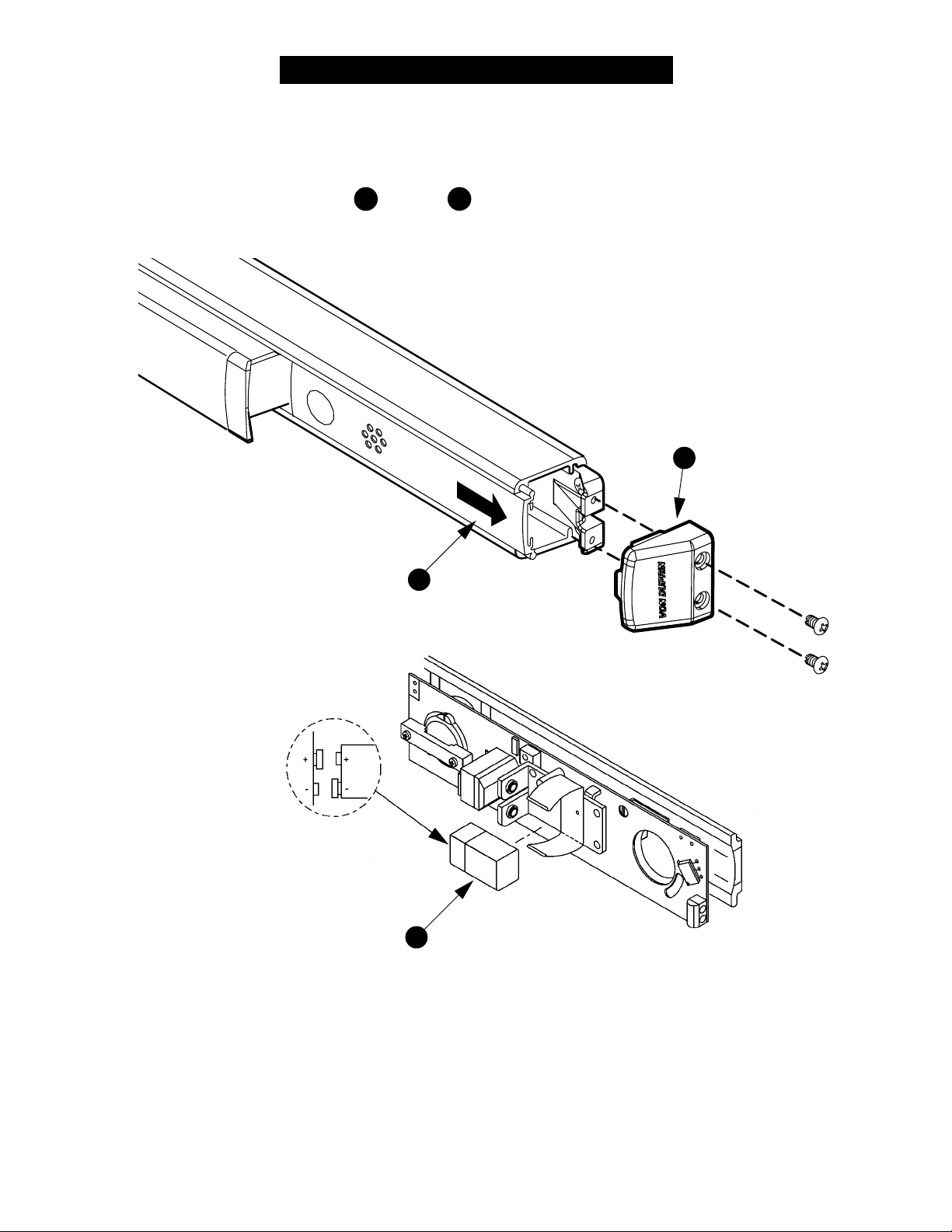
CHANGING THE BATTERY
If the battery is low, a beep will sound every 35 to 40 seconds until the battery is changed. This beeping
cannot be stopped by disarming the unit.
To change the battery, follow steps
Slide out ALK assembly B
A through C below, then reassemble.
A Remove end cap
941042_00(4)941042_00(4)
941042_00(4)
941042_00(4)941042_00(4)
Make sure
polarity
is correct
Change battery C
Page 7 of 8Page 7 of 8
Page 7 of 8
Page 7 of 8Page 7 of 8
Page 8
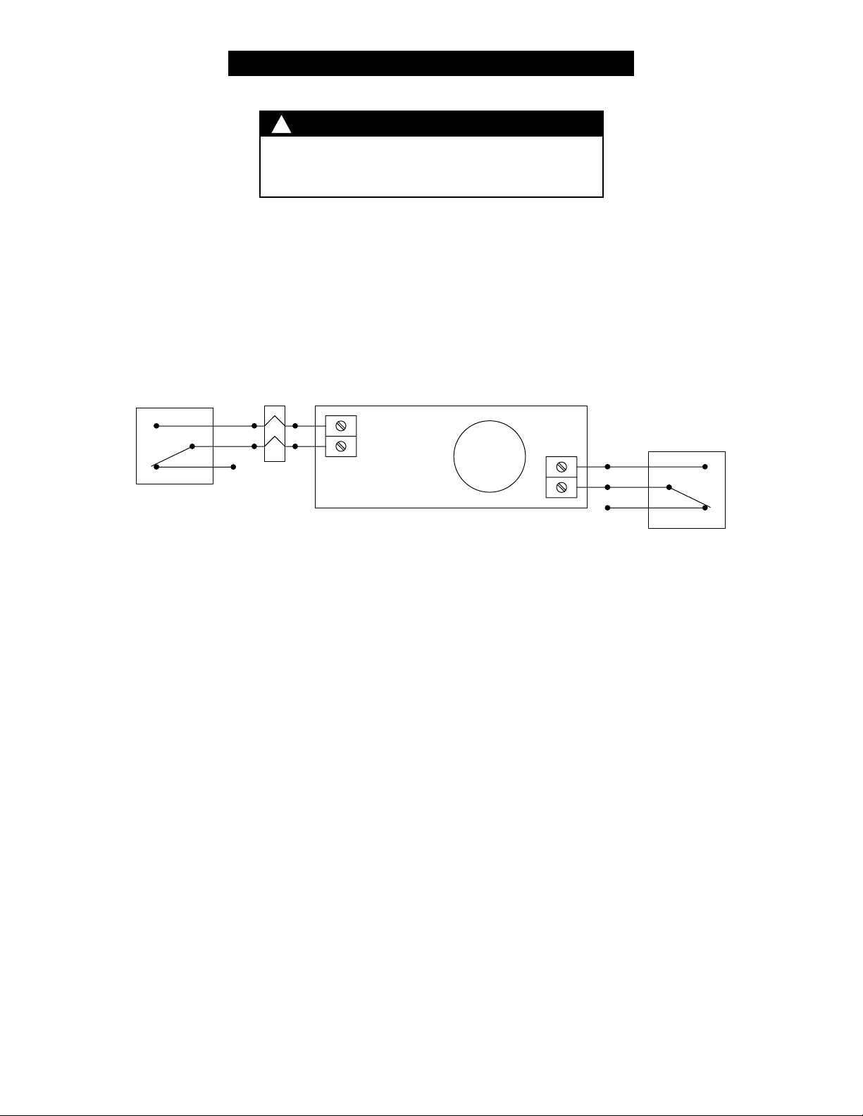
EI (EXTERNAL INHIBIT) WIRING
!
NOTE
The EI feature is optional and will not function
unless the ALK was ordered with this option.
The EI (external inhibit) option uses NO (normally open) dry access control contacts to inhibit the ALK.
Closing the access control contacts inhibits the ALK. When the access control contacts are re-opened,
the ALK re-arms after its 20-second rearm delay.
NO access
control
contacts
EPT2/10
TB2
ALK
TB1
RX Switch
Blu
Red
Yel
Page 8 of 8Page 8 of 8
Page 8 of 8
Page 8 of 8Page 8 of 8
941042_00(4)941042_00(4)
941042_00(4)
941042_00(4)941042_00(4)
 Loading...