

Page 1

Ingersoll Rand
System Automation
VX Accessory Box
Installation Manual
Before installing or starting this unit for the rst
time, this manual should be studied carefully to
obtain a working knowledge of the unit and or the
duties to be performed while operating and
maintaining the unit.
RETAIN THIS MANUAL WITH UNIT. This Technical
manual contains IMPORTANT SAFETY DATA and
should be kept with the unit at all times.
More Than Air. Answers.
Online answers: http://air.ingersollrand.com
C.C.N. : 80445083
REV. : B
DATE : JANUARY
2010
Page 2

SECTION 1 TABLE OF CONTENTS
Section 1 - table of contentS .............................2
Section 2 - intRoDUction ...................................... 3
Section 3 - Safety pRecaUtionS .........................3
INSTALLATION .............................................................................3
OPERATION ...................................................................................3
SERVICE MAINTENANCE AND REPAIR
...............................4
Section 4 - inStallation .........................................5
UNIT LOCATION ..........................................................................5
POWER SUPPLY
RS485 CONNECTION MODBUS
RS485 CONNECTION IR485
ETHERNET CONNECTION........................................................6
USB CONNECTION
SD CARD ACCESS
...........................................................................5
........................................6
.............................................. 6
.....................................................................7
....................................................................... 7
Section 5 - paRtS liSt ................................................9
Section 6 - tecHnical Data ....................................9
Section 7 - ScHeMatic ............................................10
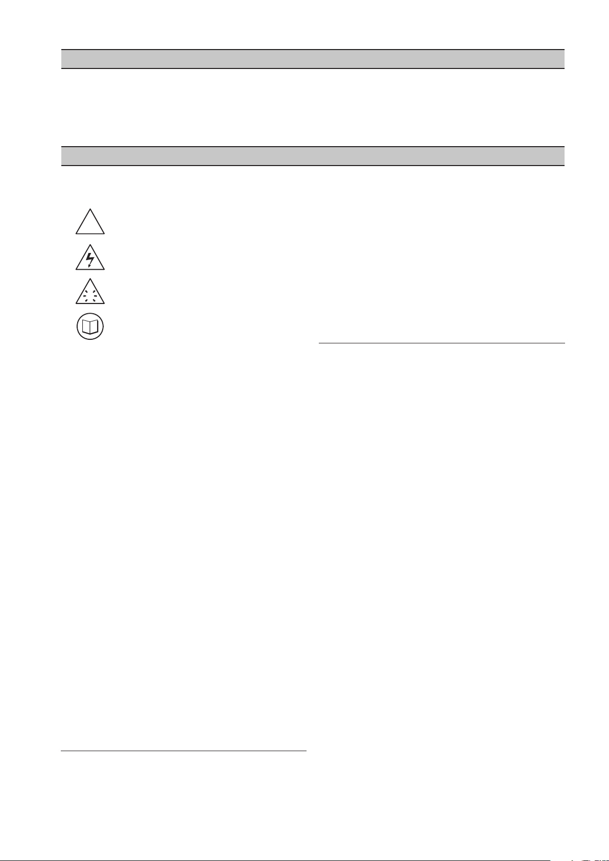
REFER TO SECTION INDICATED
NOTE
IMPORTANT OR CAUTION, SAFETY
BATTERY
LED INDICATORS
PUSH SWITCHES
......................................................................................... 8
........................................................................8
......................................................................... 8
2
Page 3
SECTION 2 INTRODUCTION
!
!
The VX box is an embedded controller that hosts a
web based visualization interface for the X8I and X12I
system controller family. The VX box is connected to
a local area network (LAN) and to the X8I/X12I’s serial
network and provides a simple web based interface that
SECTION 3 SAFETY PRECAUTIONS
ALWAYS EMPLOY SAFE WORKING PRACTICE AND
PROCEDURES
WARNING : Risk of Danger
WARNING : Risk of Electric Shock
WARNING : Risk of High Pressure
WARNING : Consult Manual
•
Before installing or operating the product, take time
to carefully read all the instructions contained in this
manual, all compressor manuals, and all manuals of
any other peripheral devices that may be installed or
connected to the unit.
•
When installing, commissioning, operating or
carrying out service or maintenance on a product,
personnel must use safe working practice and
observe all relevant local health and safety
requirements and regulations.
•
Electricity and compressed air have the potential to
cause severe personal injury or property damage.
•
Lethal voltages are used within the product. Use
extreme caution when carrying out electrical
checks. Isolate the power supply before starting any
maintenance work.
•
Maintenance must be performed by adequately
qualied personnel that are equipped with the
proper tools. If the user employs an operating
procedure, an item of equipment, or a method of
working which is not specically recommended, the
user must ensure the product will not be damaged
or made unsafe and that there is no risk to persons or
property.
•
It is not possible to anticipate every circumstance
that might represent a potential hazard. Failure
to observe safety precautions or implement safe
working practices may be considered dangerous
practice or misuse of the product.
INSTALLATION
Installation work must only be carried out by a
•
competent person under qualied supervision.
can be accessed by any computer on the LAN. The VX
box is not a server and will not initiate any trac on the
network except for optional email notications.
A fused isolation switch must be tted between the
•
main power supply and the product.
The product should be mounted in such a location
•
as to allow operational and maintenance access
without obstruction or hazard and to allow clear
visibility of indicators at all times.
If raised platforms are required to provide access
•
to the product they must not interfere with normal
operation or obstruct access. Platforms and stairs
should be of grid or plate construction with safety
rails on all open sides.
OPERATION
The product must only be operated by competent
•
personnel under qualied supervision.
Never remove or tamper with safety devices, guards
•
or insulation materials tted to the unit.
The product must only be operated at the supply
•
voltage and frequency for which it is designed.
When main power is switched on, lethal voltages are
•
present in the electrical circuits and extreme caution
must be exercised whenever it is necessary to carry
out any work on the unit.
Do not open access panels or touch electrical
•
components while voltage is applied unless it is
necessary for measurements, tests or adjustments.
Such work should be carried out only by a qualied
electrician equipped with the correct tools and
wearing appropriate protection against electrical
hazards.
All air compressors and/or other equipment
•
connected too, and controlled by, the product
should have a warning sign attached stating “THIS
UNIT MAY START WITHOUT WARNING” next to the
display panel. Please see your
provider to obtain these warning signs. Warning
signs must be placed on the control panel of the
compressor.
If an air compressor and/or other equipment
•
connected too, and controlled by, the product is to
be started remotely, attach two warning signs to
the equipment stating “THIS UNIT CAN BE STARTED
REMOTELY”. Attach one sign in a prominent location
on the outside of the equipment, and the other sign
inside the equipment control compartment.
Ingersoll Rand service
3
Page 4

4
SERVICE MAINTENANCE AND REPAIR
•
Service, maintenance, repairs or modications
must only be carried out by competent personnel
under qualied supervision.
•
If replacement parts are required, use only genuine
parts from the original equipment manufacturer, or
an alternative approved source.
•
Carry out the following operations before opening
or removing any access panels or carrying out any
work on the product:-
Isolate from the main electrical power supply.
i.
Lock th e isolator in the “OFF” position and
remove the fuses.
Attach label to the isolator switch and to the unit
ii.
stating “WORK IN PROGRESS - DO NOT APPLY
VOLTAGE”. Do not switch on electrical power or
attempt to start the unit if such a warning label is
attached.
Ensure that all instructions concerning operation
•
and maintenance are strictly followed and that
the complete unit, with all accessories and safety
devices, is kept in good working order.
The accuracy of sensor devices must be checked
•
on a regular basis. They must be calibrated when
acceptable tolerances are exceeded. Always ensure
any pressure within the compressed air system is
safely vented to atmosphere before attempting to
remove or install a sensor device.
The product must only be cleaned with a damp
•
cloth, using mild detergents if necessary. Avoid the
use of any substances containing corrosive acids or
alkalis.
Do not paint the control faceplate or obscure any
•
indicators, controls, instructions or warnings.
Page 5

SECTION 4 INSTALLATION
1
2
3
4
X01
L
N
X01
E
L
N
100-240Vac
(+-6%)
60VA, 50/60Hz
It is recommended that installation and
commissioning be carried out by an authorized and
trained product supplier.
UNIT LOCATION
The VX Box can be mounted on a wall using conventional
bolts. The VXI can be located remotely from the X8I/X12I
as long as it is within 4000 feet (1219 meters) of RS-485
cable length.
The VX box is only listed for use in a NEMA 12
environment only with cable grommets that maintain the
NEMA 12 rating of the enclosure.
POWER SUPPLY
A fused switching isolator rated at 250 VAC and 15A
maximum must be installed to the main incoming power
supply, external to the VX Box. The isolator must be tted
with a fuse of the correct rating to provide adequate
protection to the power supply cable used (in accordance
with local electrical and safety regulations). The branch
circuit fused isolator must be tted with two UL listed
2.0 A rated fuses, one on the live and one on the neutral
supply circuits. The fuses must comply with UL 248-4,
Class CC, Guide JDDZ and be contained by Class CC fuse
holders.
Apply a voltage of 100-240 Vac (+/- 6%), 60 VA, 50/ 60 Hz
to connector X01 as shown above.
A permanent earth connection to the unit’s earth
stud, as illustrated, must be implemented.
5
Page 6

6
RS485 CONNECTION MODBUS
X04
3
2
1
L2L1+
X05
3
2
1
LED6
L2L1+
RS485
MODBUS
X05
X03
3
2
1
L2L1+
X02
3
2
1
LED1
L2L1+
RS485
X02
LED X8A
CAT5e
RJ45
LED X8B
To connect to a remote modbus device the remote device
must be congured to connect at 9600 baud, 8 data bits,
no parity, and 1 stop bit. The communication cable must
be connected to terminal X04 or X05 as shown in the
gure above using Belden 9841 (or equivalent) shielded
communication cable. It should be run in grounded
conduit and should not be greater than 4000 feet (1219
meters) in length.
LED6 will ash when there is communication trac on
the Modbus port.
After powering up the VX box please allow 10 seconds
before making any Modbus requests.
the path of a power supply cable(s), always cross at
a right angle.
b)
If it is necessary to follow the route of power
supply cables for a short distance (for example:
from a compressor X12I to a wall along a
suspended cable tray) attach the RS485 or signal
cable on the outside of an earthed cable tray such
that the cable tray forms an earthed electrical
interference shield.
c)
Where possible, never route an RS485 or signal
cable near to equipment or devices that may be
a source of electrical interference (for example:
3-phase power supply transformer, high voltage
switchgear unit, frequency inverter drive module,
radio communications antenna).
RS485 CONNECTION IR485
To connect to the X8I/X12I’s ir-485 network, connect
communication cable to terminal X02 or X03 as shown
in the gure above using Belden 9841 (or equivalent)
shielded communication cable. It should be run in
grounded conduit and not be greater than 4000 feet
(1219 meters) in length.
LED1 will ash when there is communication trac on
the ir-485 port.
voltage signals can be subject to electrical interference.
This potential can result in intermittent malfunction
or anomaly that is dicult to diagnose. To avoid this
possibility always use earth shielded cables, securely
bonded to a known good earth at one end. In addition,
give careful consideration to cable routing during
installation.
RS485 data communications and other low
Never route an RS485 data communications or low
a)
voltage signal cable alongside a high voltage or 3phase power supply cable. If it is necessary to cross
ETHERNET CONNECTION
To connect the VX box to the LAN, plug a cat 5e cable
with an RJ-45 plug into the network port on the VX box.
The VX box runs at 10/100 Mbps.
LED X8A will ash to indicate that there is trac present
on the network port.
LED X8B will be o if a valid 10 Mbps link is found, or if
no link is found. LED X8B will be solid if a 100 Mbps link is
found.
Page 7

USB CONNECTION
USB-B
LED5
LED4
21
3
6 5 4
micro
micro
1
micro
micro
2
micro
micro
3
micro
micro
3
micro
micro
2
micro
micro
1
To connect a USB cable from a PC to the VX box, simply
connect a USB cable with a USB type B connector to the
USB port on the VX box.
LED4 will light if a link is established.
LED6 will ash to indicate there is communication trac.
SD CARD ACCESS
The VX box is equipped with a 1 GB micro SD card and
can use a micro SD card with a maximum of 2 GB capacity.
The VX box is NOT SDHC compatible,
To access the SD card:
1)
Before handling any electronic components touch
an exposed earthed surface to discharge any body
static.
2)
Always store electronic components in an antistatic container or package; never place on a non
anti-static surface.
3)
Handle the device by the edges; never touch the
electronic components on the device.
To insert the SD card:
Place the card in the holder on the circuit board and push
gently until it is locked in place.
Remove the cover by unscrewing the six screws shown in
the gure above to expose the circuit board.
Antistatic Precaution
The VX Box contains electronic components; take all
necessary antistatic precautions including:
To remove the SD card:
Push gently on the back of the card and let it slide back.
Remove the card from the holder, holding the card by the
edges.
7
Page 8

8
BATTERY
CR2032
3V
LED2
LED3
CPU
LED9
LED10
LED11
LED12
A
B
C
D
LED13
+VDC
The VX box uses a 3 VDC CR2032 type battery to maintain
clock settings and other system data. Under normal use
this battery should be replaced at approximately 24
month intervals.
Simply power down the VX box and replace the battery
with a new one as shown in the gure above.
LED9 will ash green if there is SD card activity detected
or red if there is no SD card activity.
LED10 will ash green if there is ir-485 connectivity, red if
there is invalid communications, or will remain o if there
is no communications detected.
LED11 and LED12 will continuously cycle red and green
to indicate proper VX box operation.
LED13 will be illuminated if the DC power supply is ok.
LED1b on the power supply and LED6b on the circuit
board also indicate correct DC power. All three must be
continuously illuminated.
PUSH SWITCHES
The VX box is equipped with two push switches on the
circuit board.
LED INDICATORS
The VX box is equipped with LED indicators to assist in
troubleshooting and verifying proper communications.
Please refer to the circuit board diagram on page 8 to see
exact location of the LEDs described below.
LED2 will illuminate if the VX box is reporting a general
fault.
LED3 will ash periodically if there is CPU activity on the
VX box.
SW1 is unused
Press and hold SW2 for two seconds to reset the VX box.
This is equivalent to cycling power on the VX box.
LEDs 9, 10, 11, and 12 indicate the current operational
state of the VX box and its communication trac.
Page 9

SECTION 5 PARTS LIST
24mm
238mm
24mm
188mm
8mm Ø
236mm
286mm
Ingersoll Rand System Automation VX Box
Item Part No. Description
- 23358047 VX Accessory Box
- 80444086 Manual, User CD
SECTION 6 TECHNICAL DATA
Dimensions 11.45” x 9.45” x 6.0”
291mm x 241mm x 152mm
Weight 14Ib (6.5kg)
Mounting wall, 4 x screw xings
Enclosure IP54, NEMA 12
Supply 100-240Vac +/- 6%
Power 60VA
Temperature 0°C to 46°C (32°F to 115°F)
Humidity 95% RH non-condensing
INSTALLATION AND MOUNTING DIMENSIONS:
9
Page 10

SECTION 7 SCHEMATIC
FH1
T
1
.
6
A
FH2
1
2
3
4
X01
L
N
T
1
.
6
A
X01
PSU
N
L
E
0VDC
+VDC
E
L
N
100-240Vac
(+-6%)
60VA
50/60Hz
CR2032
3V
IEC
20 x 5mm
RJ45 - CAT5e
Ethernet
10/100 BaseT
USB-B
RJ11
56k Modem
Analogue
X03
3
2
1
L2L1+
X02
3
2
1
X04
3
2
1
X05
3
2
1
LED1
LED6
LED7
LED5
LED4
LED6b
SW1
SW2 X09
LED2
LED9
LED10
LED 11
LED12
LED1b
LED13
LED3
LED X8B
LED X8A
CR2032
micro
LED8
L2L1+
L2L1+
L2L1+
Modbus
micro
D
C
B
A
up to 2GB
Air
4 85 TM
10
Page 11

Page 12

LOOK WHAT INGERSOLL RAND CAN DO FOR YOU!
Ecient Field Service
We maintain a highly trained sta of technicians
to service your equipment for preventive
maintenance, or to assist you should emergencies
ever occur.
Complete Repair Service
Our trained technicians will repair or overhaul
your equipment to factory specications,
using only genuine Ingersoll Rand parts.
Special Engineering Service
We can help you identify and solve your problems
by evaluating your needs and recommending
theproper equipment to give your maximum
eciency.
Spare Parts
By stocking genuine Ingersoll Rand spare
parts, we can help you avoid costly delays
or substituting inferior parts. Using genuine
Ingersoll Rand parts on you Ingersoll
Rand equipment will help to keep even
older equipment running in good-as-new
Complete Stock of Equipment
We carry a complete line of Ingersoll Rand
equipment and accessories designed to meet
any compressed air application. We are backed
by Ingersoll Rand’s prompt factory shipment to
ensure you on-time delivery.
condition.
A SUBSTITUTE IS NOT A REPLACEMENT!
Ensure you get peak performance and longevity out of your Ingersoll Rand product by insisting on genuine Ingersoll
Rand replacement parts and maintenance kits. Not only are the replacement parts made to precise dimensions and OEM-
specied metallurgy, but each part is backed by the Ingersoll Rand warranty. Your local Customer Center, Distributor, or
direct Ingersoll Rand salesperson will work with your to ensure you get the parts you need to do the job right. Equip your
machines with only the best Ingersoll Rand genuine parts.
NOTE: THE USE OF REPAIR PARTS OTHER THAN THOSE INCLUDED WITHIN THE INGERSOLL RAND COMPANY
APPROVED PARTS LIST MAY CREATE UNSAFE CONDITIONS OR MECHANICAL FAILURES OVER WHICH INGERSOLL
RAND COMPANY HAS NO CONTROL. INGERSOLL RAND COMPANY SHALL BEAR NO RESPONSIBILITY FOR
EQUIPMENT ON WHICH NON-APPROVED REPAIR PARTS ARE INSTALLED.
The manufacturer reserves the right to make changes or add improvements without notice and without incurring any
obligation to make such changes to products previously sold.
 Loading...