

Page 1

Before installing or starting this unit for the first time, this
manual should be studied carefully to obtain a working
knowledge of the unit and/or the duties to be performed while
operating and maintaining the unit.
RETAIN THIS MANUAL WITH UNIT. This Technical
manual contains IMPORTANT SAFETY DATA and should
be kept with the unit at all times.
More Than Air Answers.
Online answers: http://www.air.irco.com
Ingersoll Rand
System Automation
IO Box MODBUS RTU
User’s Manual
C.C.N. : 80445018
REV. B
DATE: JUNE 2009
Page 2

SECTION 1 – TABLE OF CONTENTS
SECTION 1 – TABLE OF CONTENTS .................................................................................................................... 2
SECTION 2 - INTRODUCTION ................................................................................................................................ 3
SECTION 3 - SAFETY PRECAUTIONS .................................................................................................................. 3
SECTION 4 - MODBUS RTU ................................................................................................................................... 5
MODBUS TABLE(S) ............................................................................................................................................. 5
MODBUS RTU ...................................................................................................................................................... 5 U
COMMUNICATION LINK ...................................................................................................................................... 5
RS485 SERIAL DATA FORMAT ........................................................................................................................... 5
MESSAGE DATA FORMAT ................................................................................................................................. 5
SLAVE RESPONSE TIMEOUT ............................................................................................................................ 7
MESSAGE ANSWER FROM SLAVE TO MASTER .............................................................................................. 7
EXCEPTION RESPONSE .................................................................................................................................... 8
TROUBLESHOOTING ......................................................................................................................................... 8
SECTION 5 - MODBUS TABLE DESCRIPTION ..................................................................................................... 9
TABLE ITEM FORMAT ......................................................................................................................................... 9
NAME AND FUNCTION ....................................................................................................................................... 9
CODING ............................................................................................................................................................... 9
MENU REFERENCE .......................................................................................................................................... 10
‘ADV’ ADVISE FUNCTION ................................................................................................................................. 10
‘ADV’ ADVISE FUNCTION – SINGLE ITEM FORMAT OPTION ........................................................................ 10
‘CMD’ COMMAND FUNCTION ........................................................................................................................... 12
‘GET’ FUNCTION ............................................................................................................................................... 13
‘SET’ FUNCTION ................................................................................................................................................ 13
DATA CODING DEFINITIONS: .......................................................................................................................... 14
DATA TYPES ...................................................................................................................................................... 14
DATA UNITS ....................................................................................................................................................... 15
SECTION 6 - X-SERIES AIR SYSTEM .................................................................................................................. 17
SMG BOX ........................................................................................................................................................... 18
GENERAL X-SERIES SYSTEM COMPONENTS .............................................................................................. 18
X-SERIES NETWORK ADDRESSES................................................................................................................. 19
COMMUNICATION LINK .................................................................................................................................... 19
MODBUS TIMING............................................................................................................................................... 19
RS485 MODBUS SERIAL DATA FORMAT ........................................................................................................ 19
SECTION 7 – IO BOX MODBUS RTU DEFINITIONS ........................................................................................... 20
2
Page 3
SECTION 2 - INTRODUCTION
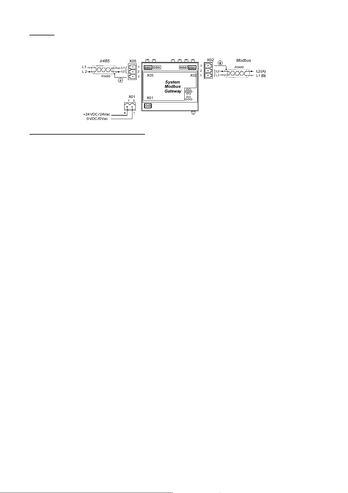
System MODBUS Gateway (SMG Box) communication is RS485, RTU, Master-Slave configuration. The SMG Box acts as
a transparent interface to enable a remote ‘master’ device to be able to communicate with the X-Series Units and th e
Intellisys Controllers via the ir485 network ‘slave’ device(s). The MODBUS RTU data construction and formatting for a
‘master’ device is the subject of this document. This information is intended for a systems integrator to facilitate set-up of a
‘master’ device in order to communicate successfully with the X-Series Units and the Intellisys Controllers through a SMG
Box.
SECTION 3 - SAFETY PRECAUTIONS
WARNING :
!
WARNING :
WARNING :
!
WARNING :
• Before installing or operating the
SYSTEM MODBUS GATEWAY (SMG)
BOX, take time to carefully read all the
instructions contained in this manual, all
compressor manuals, and all manuals
of any other peripheral devices that may
be installed or connected to the unit.
• Electricity and compressed air have the
potential to cause severe personal injury
or property damage.
• The operator should use common sense
and good working practices while
operating and maintaining this system.
All applicable codes should be strictly
adhered to.
• Maintenance must be performed by
adequately qualified personnel that are
equipped with the proper tools.
INSTALLATION
• Installation work must only be carried
out by a competent person under
qualified supervision.
• A fused isolation switch must be fitted
between the main power supply and the
SYSTEM MODBUS GATEWAY (SMG)
BOX.
• The SYSTEM MODBUS GATEWAY
(SMG) BOX should be mounted in such
a location as to allow operational and
maintenance access without obstruction
or hazard and to allow clear visibility of
indicators at all times.
• If raised platforms are required to
provide access to the SYSTEM
MODBUS GATEWAY (SMG) BOX,
they must not interfere with normal
operation or obstruct access. Platforms
and stairs should be of grid or plate
construction with safety rails on all open
sides.
Risk of Danger
Risk of Electric Shock
Risk of High Pressure
Consult Manual
OPERATION
• The SYSTEM MODBUS GATEWAY
(SMG) BOX must only be operated by
competent personnel under qualified
supervision.
• Never remove or tamper with safety
devices, guards or insulation materials
fitted to the SYSTEM MODBUS
GATEWAY (SMG) BOX.
• The SYSTEM MODBUS GATEWAY
(SMG) BOX must only be operated at
the supply voltage and frequency for
which it is designed.
• When main power is switched on,
lethal voltages are present in the
electrical circuits and extreme caution
must be exercised whenever it is
necessary to carry out any work on
the unit.
• Do not open access panels or touch
electrical components while voltage is
applied unless it is necessary for
measurements, tests or adjustments.
Such work should be carried out only
by a qualified electrician equipped
with the correct tools and wearing
appropriate protection against
electrical hazards.
• All air compressors and/or other
equipment connected to the unit
should have a warning sign attached
stating “THIS UNIT MAY START
WITHOUT WARNING” next to the
display panel.
• If an air compressor and/or other
equipment connected to the unit is to
be started remotely, attach two
warning signs to the equipment
stating “THIS UNIT CAN BE
STARTED REMOTELY”. Attach one
sign in a prominent location on the
outside of the equipment, and the
other sign inside the equipment
control compartment.
3
Page 4

MAINTENANCE AND REPAIR
• Maintenance, repairs or modifications
must only be carried out by competent
personnel under qualified supervision.
• If replacement parts are required, use
only genuine parts from the original
equipment manufacturer, or an
alternative approved source.
• Carry out the following operations
before opening or removing any access
panels or carrying out any work on the
SYSTEM MODBUS GATEWAY (SMG)
BOX:
i. Isolate the SYSTEM MODBUS
GATEWAY (SMG) BOX from
the main electrical power
supply. Lock the isolator in the
“OFF” position and remove the
fuses.
ii. Attach labels to the isolator
switch and to the unit stating
“WORK IN PROGRESS - DO
NOT APPLY VOLTAGE”. Do
not switch on electrical power
or attempt to start the SYSTEM
MODBUS GATEWAY (SMG)
BOX if such a warning label is
attached.
• Make sure that all instructions
concerning operation and maintenance
are strictly followed and that the
complete unit, with all accessories and
safety devices, is kept in good working
order.
• The accuracy of sensor devices must be
checked on a regular basis. They must
be calibrated when acceptable
tolerances are exceeded. Always
ensure any pressure within the
compressed air system is safely vented
to atmosphere before attempting to
remove or install a sensor device.
• The SYSTEM MODBUS GATEWAY
(SMG) BOX must only be cleaned with
a damp cloth, using mild detergents if
necessary. Avoid the use of any
substances containing corrosive acids
or alkalis.
• Do not paint the control faceplate or
obscure any indicators, controls,
instructions or warnings
4
Page 5
SECTION 4 - MODBUS RTU
MODBUS TABLE(S)
This document discusses generic MODBUS communications and how to implement the software specific ‘MODBUS Table’
information. MODBUS communication formatting may differ from controller to controller and you may require more than one
‘MODBUS Table’.
Always check the software variant identification and version number for a controller or unit with the variant and version of
the ‘MODBUS Table’ supplied. In some instances the information contained in a ‘MODBUS Table’ may not be ap plicable to
a controller or unit installed with the same software variant but a different version number.
MODBUS RTU
MODBUS RTU (Remote Terminal Unit) is a master-slave type protocol. An X-Series Automation System Controller or
Intellisys Controller functions as the slave device. Information requests or commands are communicated from master to
slave only through a System Modbus Gateway Box (SMG). The SMG Box will always respond to communications from a
remote master device in accordance with the MODBUS RTU protocol standard.
The MODBUS protocol is used to communicate with personal computers (PC), Programmable Logic Controllers
(PLC’s), or Distributed Control Systems (DCS) over the Network port. The SMG Box only responds to three MODBUS
commands, Read Holding Register 03 (03 Hex), Preset Single Register 06 (06 Hex), and Preset Multip le Registers
command 16 (10 Hex) (See Modicon MODBUS Protocol Reference Guide, PI-MBUS-300 Rev. J, for more details on
MODBUS).
COMMUNICATION LINK
MODBUS is implemented using a two-wire RS485 industry standard communications link operating in master-slave mode.
Polarity of the two RS485 wires (L1+ and L2-) is important; reversal will disrupt communications.
RS485 SERIAL DATA FORMAT
The RS485 MODBUS port is a 2-wire operating with an asynchronous serial data format:
8 data bits / no parity / 1 stop - (8,N, 1) - transmitted at 9600 baud.
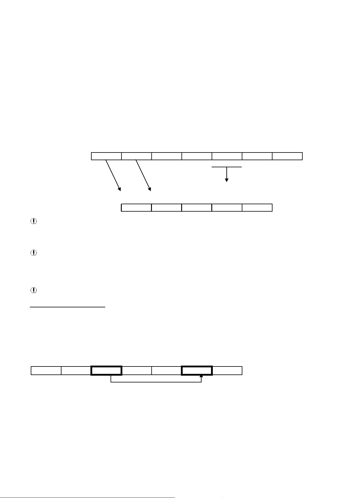
MESSAGE DATA FORMAT
The bytes of the MODBUS RTU message must be sent in one message package. The RTU protocol allows for a maximum
pause of 1.5 byte-times between 2 consecutive bytes of a message.
A pause longer than 1.5 byte-times will render the message invalid and it will be ignored.
Message data format is dependant on function and will consist of a combination of the following elements:
1) Destination address (slave network address)
2) Function Code
3) Data start address (slave register start address)
4) Number of registers, number of bytes of data
5) Message data
6) CRC checksum
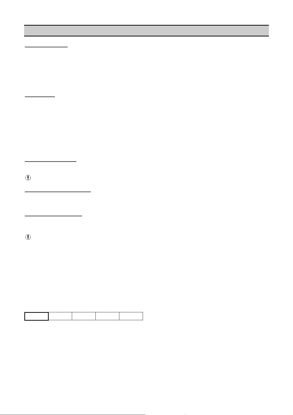
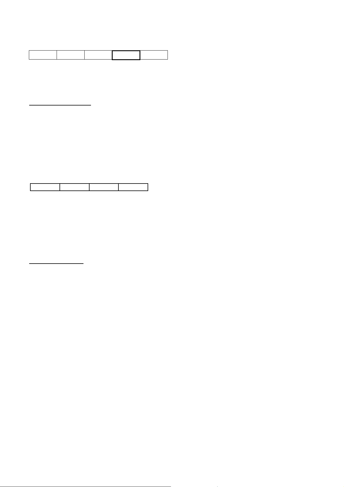
Message Destination Address
Slave
Address
Function
Code
Start
Address
Number of
Registers
CRC Check
Sum
01 03 40 06 00 02 30 CA
The ‘destination address’ must be correct for the ‘slave’ controller device for which the message is inten ded. An address can
be from 01Hex to EFHex. The SMG Box is transparent and addresses must be for the destination ‘slave’ controller or unit.
Each controller or unit must be set with a unique address.
5
Page 6
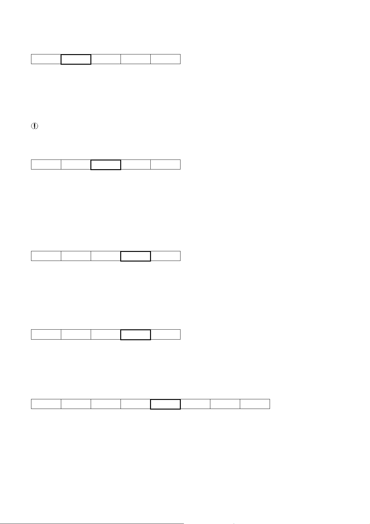
Message Function Codes
Slave
Address
Function
Code
Start
Address
Number of
Registers
CRC Check
Sum
01 03 40 06 00 02 30 CA
The message function code defines the required data processing operation of the slave controller. Although several types of
message function codes are defined by the MODBUS standard, only the message function code types working directl y with
registers are implemented on controller units:
03H Read Holding Register(s) – Get (Get Data) or Adv (Advise Data) (X-Series) and Read (Intellisys)
06H Preset Single Register - Write (Intellisys Only)
10H Preset Multiple Registers – Set (Set Data) or Cmd (Command Instruction) (X-Series only)
Any other message function code type will result in an EXCEPTION response.
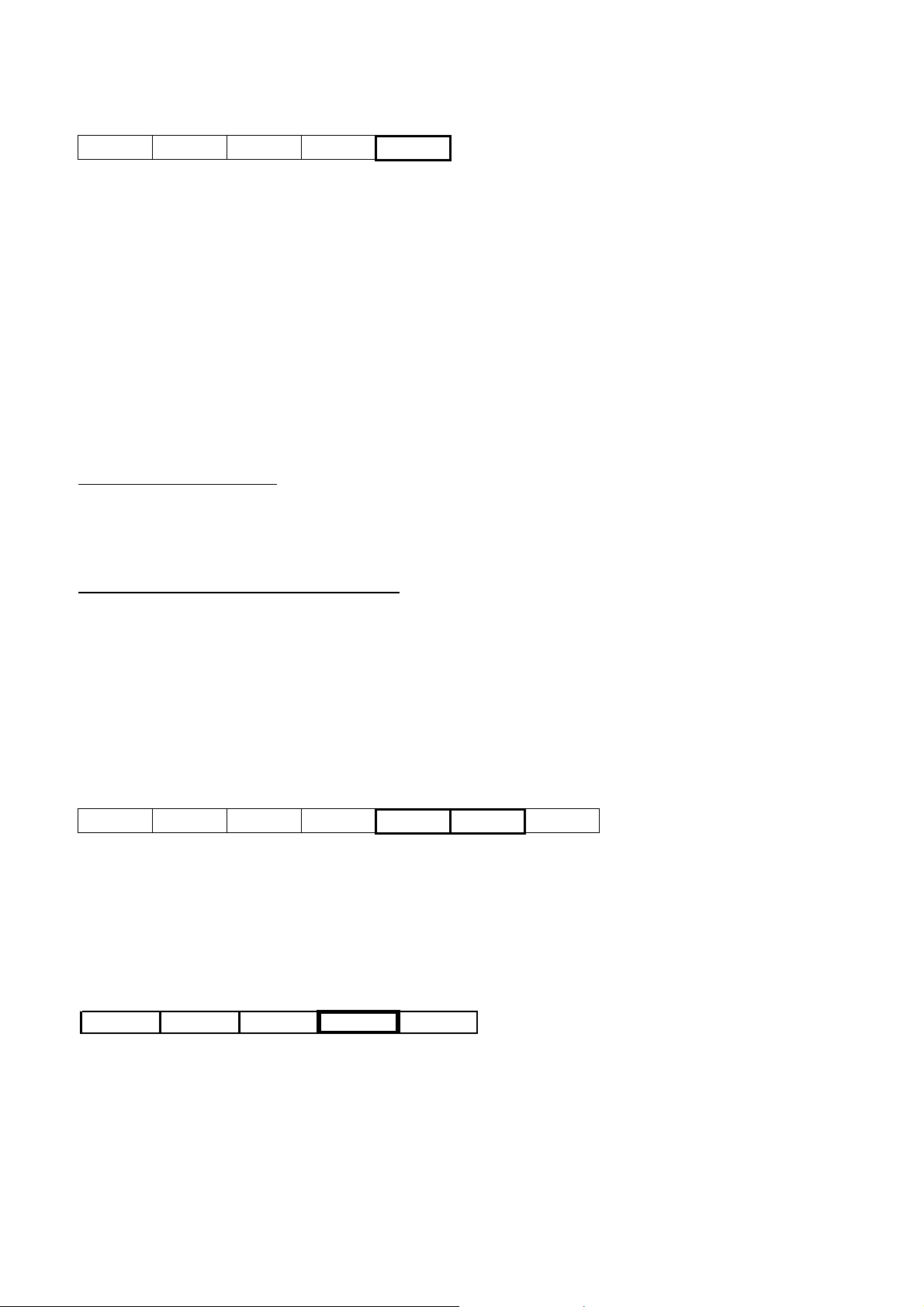
Message Data Start Address
Slave
Address
Function
Code
Start
Address
Number of
Registers
CRC Check
Sum
01 03 40 06 00 02 30 CA
The message data start address (16bit word) designates the initial register address location in the contr oller from which the
data is processed. Start address information is contained in the ‘MODBUS Table’.
Note: high-byte transmitted first followed by low-byte.
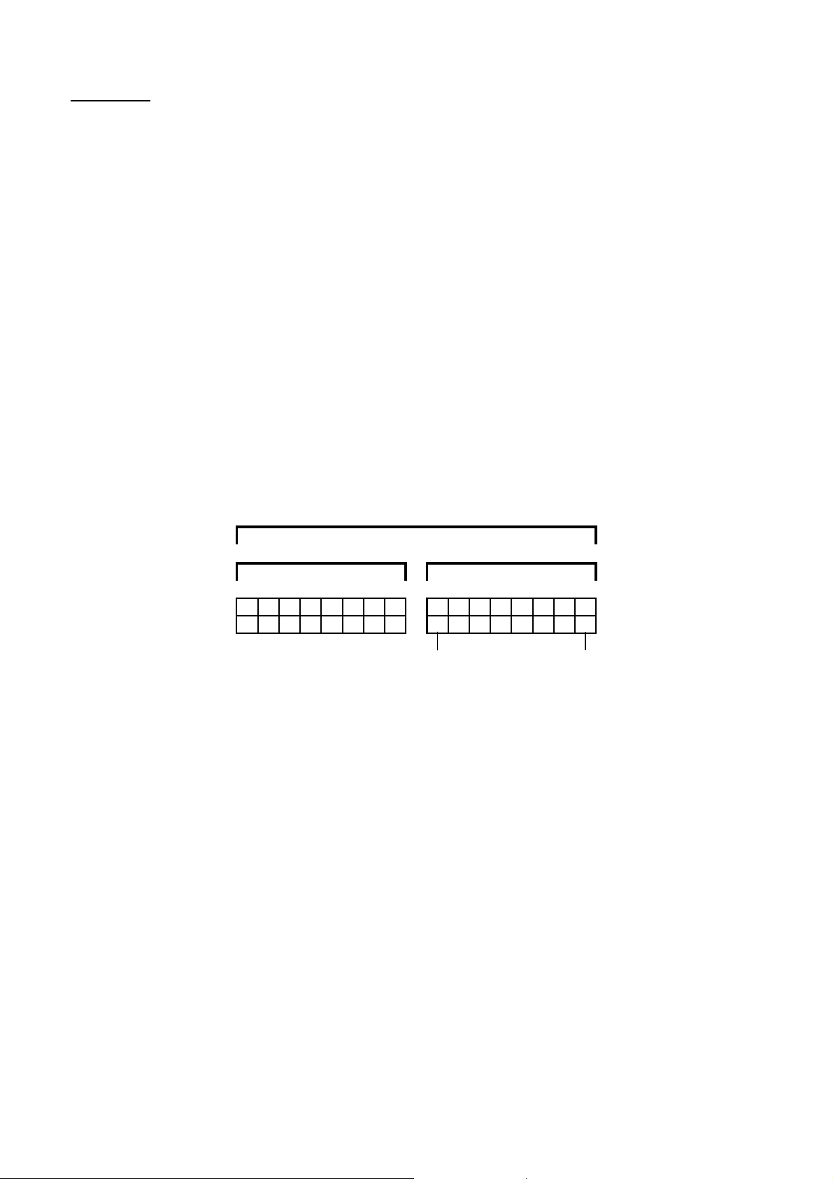
Message Data
The message data content depends on the message function code type.
03H Read Holding Register(s) – Get (Get Data), Adv (Advise Data) (X-Series) or Read (Intellisys)
Slave
Address
Function
Code
Start
Address
Number of
Registers
CRC Check
Sum
01 03 40 06 00 02 30 CA
Slave address + function code ’03 Hex’ + start address of registers in slave memory + 16bit integer value that determines
the size (in 16bit ‘word’ registers) of the message data being requested (00 02 = 2 registers of data). This is the number of
16bit registers to read. A maximum of 32 registers can be read at one time. This information is contained in the ‘MODBUS
Table’.
06H Preset Single Register - Write (Intellisys Only)
Slave
Address
Function
Code
Start
Address
DATA
byte 0 byte 1
CRC Check
Sum
01 06 00 6F 00 5F FE BC
Slave address + function code ’06 Hex’ + start address of register(s) in slave memory to be set then the ‘data’ itself. This
information is contained in the ‘MODBUS Table’.
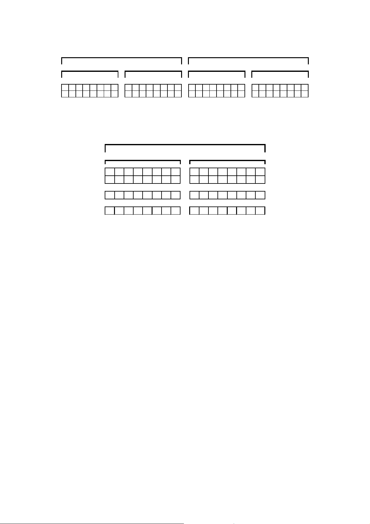
10H Preset Multiple Registers – Set (Set Data) or Cmd (Command Instruction) (X-Series only)
Slave
Address
Function
Code
Start
Address
Number of
Registers To
Be Set
Number of
Bytes of
Data
DATA
1st Register
byte 0 byte 1
DATA
2nd Register
byte 2 byte 3
CRC Check
Sum
01 10 40 18 00 02 04 00 00 1B 5F 88 0E
Slave address + function code ’10 Hex’ + start address of register(s) in slave memory to be set + 16bit (integer valve of the
number of registers to be set) + 8bit ‘byte’ (integer value for the number of following data bytes) then the ‘data’ itself. This
information is contained in the ‘MODBUS Table’.
Note: A function ’10 Hex’ Set message also requires an additional byte defining the number of ‘data’ bytes in the data
message. This will always be the number of ‘registers’ multiplied by 2 as each ‘data’ register consists of 2 bytes (if number
of ‘data’ registers = 2 then number of ‘data’ bytes = 4).
6
Page 7
Message CRC Checksum
Slave
Address
Function
Code
Start
Address
Number of
Registers
CRC Check
Sum
01 03 40 06 00 02 30 CA
The CRC (Cyclical Redundancy Check) is a check-sum generated by means of ‘A001H polynomial’.
The CRC is two bytes containing a 16-bit binary value (word). The CRC value is calculated by the transmitting device that
appends the CRC to the end of the message. The receiving device recalculates the CRC value prior to processing of a
received message and compares the result to the actual CRC value appended to the message. If the two values do n ot
match the message is regarded as invalid. The CRC is initiated by first preloading a 16bit register to all 1's (FFFF Hex).
Then a process begins of applying each consecutive 8bit byte of the message to the register contents us ing an exclusive
‘OR’ calculation. The result is shifted one bit in the direction of the least significant bit (LSB), with the most significant bit
(MSB) set at ‘0’. The LSB is then examined; if ‘1’ the register content is applied to the polynomial value ‘A001’ Hex (101 0
0000 0000 0001) using an exclusive ‘OR’ calculation - if ‘0’ no exclusive OR takes place. This process is repeated until eight
‘bit’ shifts have been performed. After the eighth bit shift, the next 8bit message byte is applied to the register contents using
an exclusive ‘OR’ calculation. The bit shift and re-calculation process is then repeated again. When all message bytes have
been processed the final content of the 16bit register is the message CRC value.
Only the 8bits of ‘data’ in each message character is used for generating the CRC; start, stop and parity bits are ignored.
Note: When the 16bit CRC value is appended to a message, the low order byte must be transmitted first followed by the
high order byte. An incorrect or byte reversed check sum will render the message invalid and it will be ignored.
SLAVE RESPONSE TIMEOUT
A slave controller may not answer immediately. Ensure the ‘slave timeout’ setting of the ‘master’ device is set to a value no
less than 500ms. If the ‘slave’ device fails to receive a valid message due to a communication disruption, parity error, CRC
error or other reasons, no response is given and the master must process a timeout condition in this instance. If the ‘slave’
receives a valid message that cannot be processed an exception response will be returned.
MESSAGE ANSWER FROM SLAVE TO MASTER
The format of the ‘slave’ controller answer is similar to the original master request format; the message data content
depends on the message function code type.
The ‘address’ and ‘code’ of the slave answer is identical to the original request message; the address is the ‘slave’ device
address and the ‘code’ is a repeat of received function code type from the master. The remainder of the message is
dependant on the requested function code type. The CRC checksum is re-calculated for the answer message character s
using the specified CRC process.
03Hex – Get: read from register (or ‘Adv’ Advise)
Slave
Address
Function
Code
Start
Address
Number of
Bytes of
Data
DATA
1st Register
byte 0 byte 1
DATA
2nd Register
byte 2 byte 3
CRC Check
Sum
01 03 40 18 04 00 00 1B 5F BE 61
1) slave address 1byte
2) function code 1byte
3) bytes of data 1byte (number of bytes in ‘data’ answer)
4) data (high byte of each register transmitted first)
5) CRC checksum 2bytes (low byte first followed by high byte)
06Hex - Preset Single Register: write to single register
Slave Address Function Code Start Address
DATA
byte 0 byte 1
CRC Check Sum
01 06 00 6F 00 5F FE BC
1) slave address 1byte
2) function code 1byte
3) bytes of data 1byte (number of bytes in ‘data’ answer)
4) data (high byte of each register transmitted first)
5) CRC checksum 2bytes (low byte first followed by high byte)
7
Page 8
10H Preset Multiple Registers – Set (Set Data) or Cmd (Command Instruction) (X-Series only)
Slave
Address
Function
Code
Start
Address
Number of
Registers
CRC Check
Sum
01 10 40 18 00 02 D4 0F
1) slave address 1byte
2) function code 1byte
3) number of registers set 2 bytes
4) CRC checksum 2 Bytes (low byte first followed by high byte)
EXCEPTION RESPONSE
If the ‘slave’ device receives a request that cannot be processed an ‘exception response’ is given. An exception response
message consists of the following elements:
1) Slave Network Address (1 byte): Slave address identification
2) Function Code (1 byte): In a normal response, the slave repeats the function code of the original master request. All
function codes have an MSB (most significant bit) of 0 (values are all below 80 hexadecimal). In an exception response,
the slave sets the MSB of the function ‘code’ to 1. This makes the ‘code’ value 80 Hex greater than the received ‘code’
value from the master.
3) Data (1 byte): The ‘data’ response will contain a ‘1 byte’ value exception code.
4) CRC Checksum (2 byte).
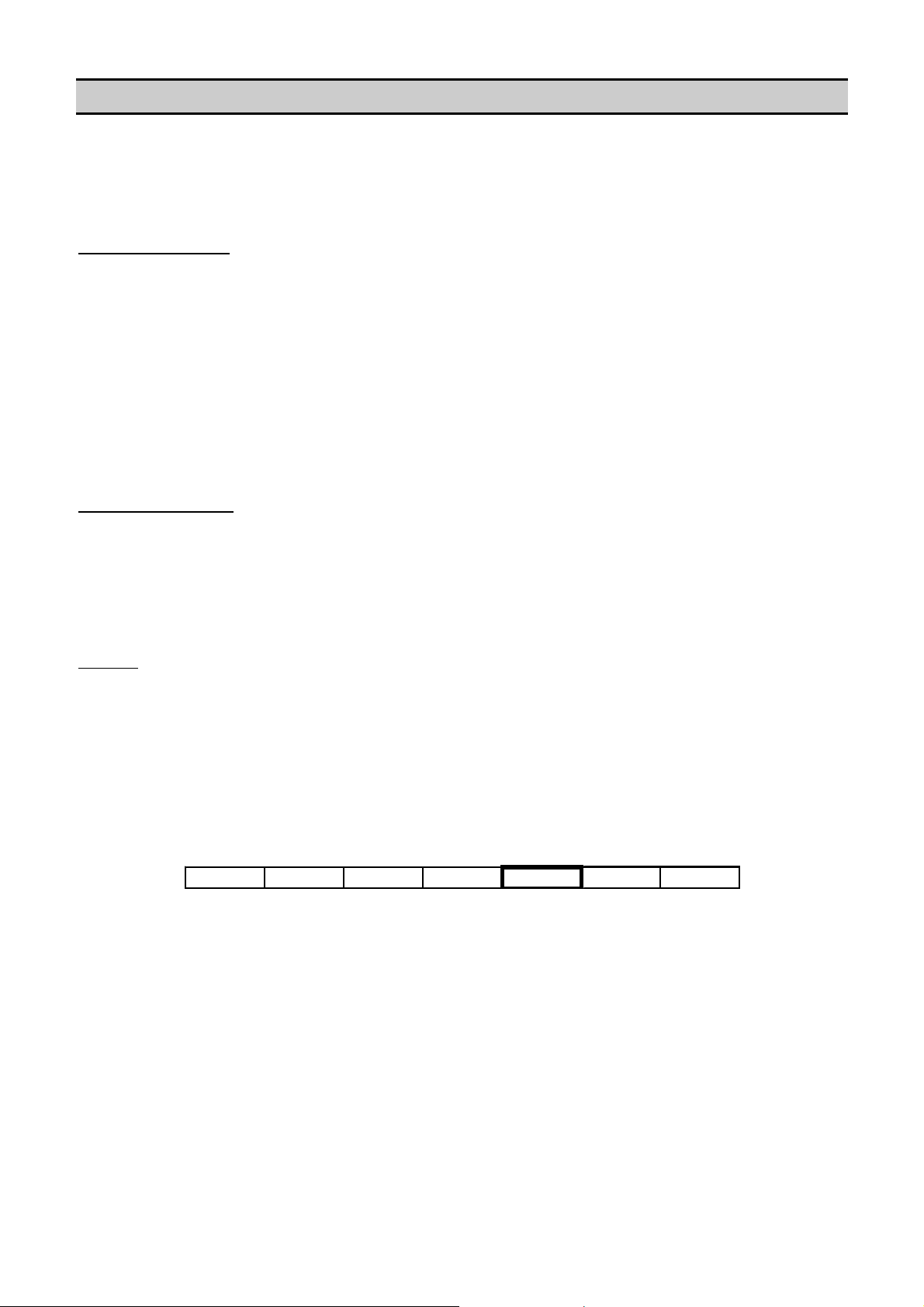
CRC Check SumSlave Address Function Code Error Code
01 90 04 4D C3
Exception Codes:
01H Illegal Function Code
The requested ‘code’ function is not supported.
02H Illegal Data Address
The requested ‘data start address’ is not supported.
03H Illegal Data Value
The requested ‘data’ value is not supported.
04H Function Error
The slave cannot execute the request or the request type is inhibited.
TROUBLESHOOTING
Problem: No ‘slave’ response or corrupt MODBUS message
Solution: Check that the ‘slave’ controller is set for the anticipated slave address
Check that all ‘slave’ controllers are set with a unique system address
Check that the controller is set for MODBUS RTU mode (if applicable)
Check that the ‘master’ is operating in MODBUS RTU mode
Check that the ‘master’ baud rate, parity bit and number of s t op bits are correct
Check that the ‘master ‘response timeout is set for a minimum of 500ms
Check that the ‘master’ is implementing the specified CRC check sum process
Check RS485 wiring polarity and security of connections
Problem: Last character of MODBUS message is corrupted
Solution: Add a delay of 2ms after last character received before releasing RTS signal
Problem: The MODBUS master message is reflected in the slave answer
Solution: Inhibit RX/TX echo on ‘master’ device communications port
8
Page 9
SECTION 5 - MODBUS TABLE DESCRIPTION
A ‘MODBUS table’ describes the “items” used to access information in the memory registers of different types of controller,
or similar controllers using different application software variants or versions. The MODBUS Table will contain the valid
message items (“Name”) together with the Function Code (Function), Register Start Address (“Register Address”), Register
Size (“Register Length”) and a definition for coding and decoding the item data (“Coding”). A ‘MODBUS Table’ order form,
detailing the required order information, can be found on the last page of this document.
TABLE ITEM FORMAT
Each ‘item’ of a ‘MODBUS Table’ will define the massage format to read or set the information contained in the slave
controller register(s):-
Name
Descriptive ‘name’ or ‘item tag’ for the data item. The ‘Name’ is not used in code or message
formatting and serves only as a reference for the defined item.
Function
The Hex code required that instructs the slave (Intellisys controller) to perform a GET, ADV
(Advise), CMD (command) or SET function.
Register Address
Register Length
Coding
Menu
The slave controller register start address for the defined processing function.
The number of registers to be processed.
How to construct or interpret the data elements of a message.
Controller menu item reference.
Note: see “MODBUS RTU” for a detailed description of ‘Function’, ‘Register Address’ and ‘Register Length’ formats.
NAME AND FUNCTION
The ‘name’ for each table item will always start with 3 characters that describe the function type:
Adv Advise Function (03Hex) – same format as a Get function, see ‘Advise Function’.
Get Read from register (03Hex)
Set Write to registe r (10Hex)
Cmd Command (10Hex) – same format as a Set function; will instruct the slave to perform a defined action or
process
CODING
Item coding definitions specify the ‘number of data bytes’ and the ‘data conversion type’. In some instances a data message
may contain multiple sets of data items; an ‘Advise’ message for example. In this instance the ‘start location of data’ within
the message is also specified to enable extraction of the required data item from the entire message data.
Number of data bytes:
This specifies the length of the item data in bytes (6 = 6 bytes (3 registers) of data)
Start location of data bytes:
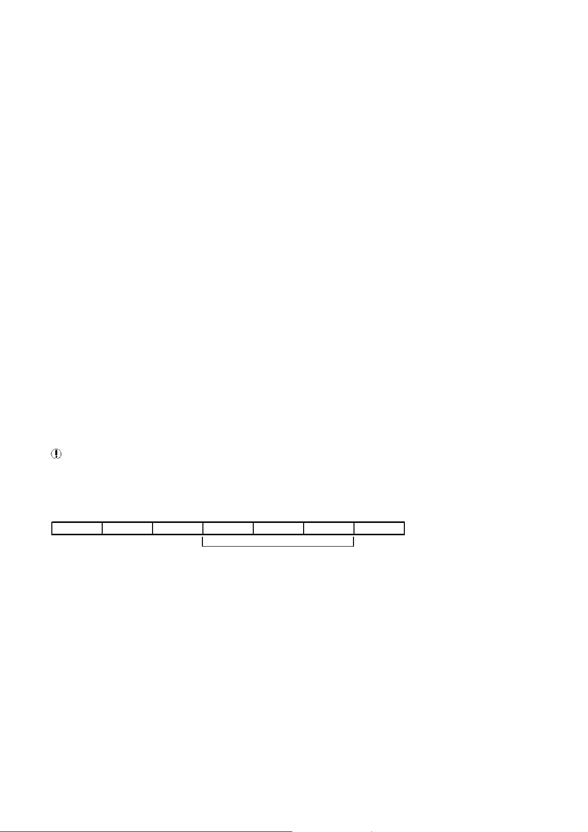
Number of Data
Bytes to Follow
DATA
1st Register byte
0 byte 1
DATA
2nd Register
byte 2 byte 3
DATA
3rd Register byte
4 byte 5
CRC Check SumSlave Address Function Code
01 03 06 09 00 00 65 00 A8 30 4D
If a data message consists of more than one set of data items (multiple item data message) the ‘start location’ specifies
where the first byte of the data associated with in item begins. If, for example, a 6 byte (3 register) answer is returned that
consists of three different ‘2 byte’ item data values, a ‘start location of data bytes’ = ‘2’ indicates that the item data starts with
the 3rd byte (byte 2) of the data message. The 1st byte of a data message is regarded as byte 0(zero). In this instance the
‘number of data bytes’ will be ‘2’ indicating that the data associated with the item is 2 bytes of data in length. A ‘start
location’ of byte ‘2’ and register length of ‘1’ (register = 2 bytes) means the data is contained in the 3rd and 4th bytes of the
data message. If no ‘start location’ is specified then data associated with the item will start with the first byte (byte 0) of the
message data.
Data Conversion Type:
This specifies how to interpret the data; refer to the ‘Data Conversion Type’ list in the Modbus Table.
For example: If the ‘Data Conversion Type’ = CODED, STATUS then the decimal integer value of the data has a defined
meaning; refer to the ‘STATUS’ Coded data list in the ‘MODBUS Table’ for definitions. If the ‘Data Conversion Type’ = PSI
then the decimal integer value of the data is ‘pressure’ in ‘psi’ units.
9
Page 10
MENU REFERENCE
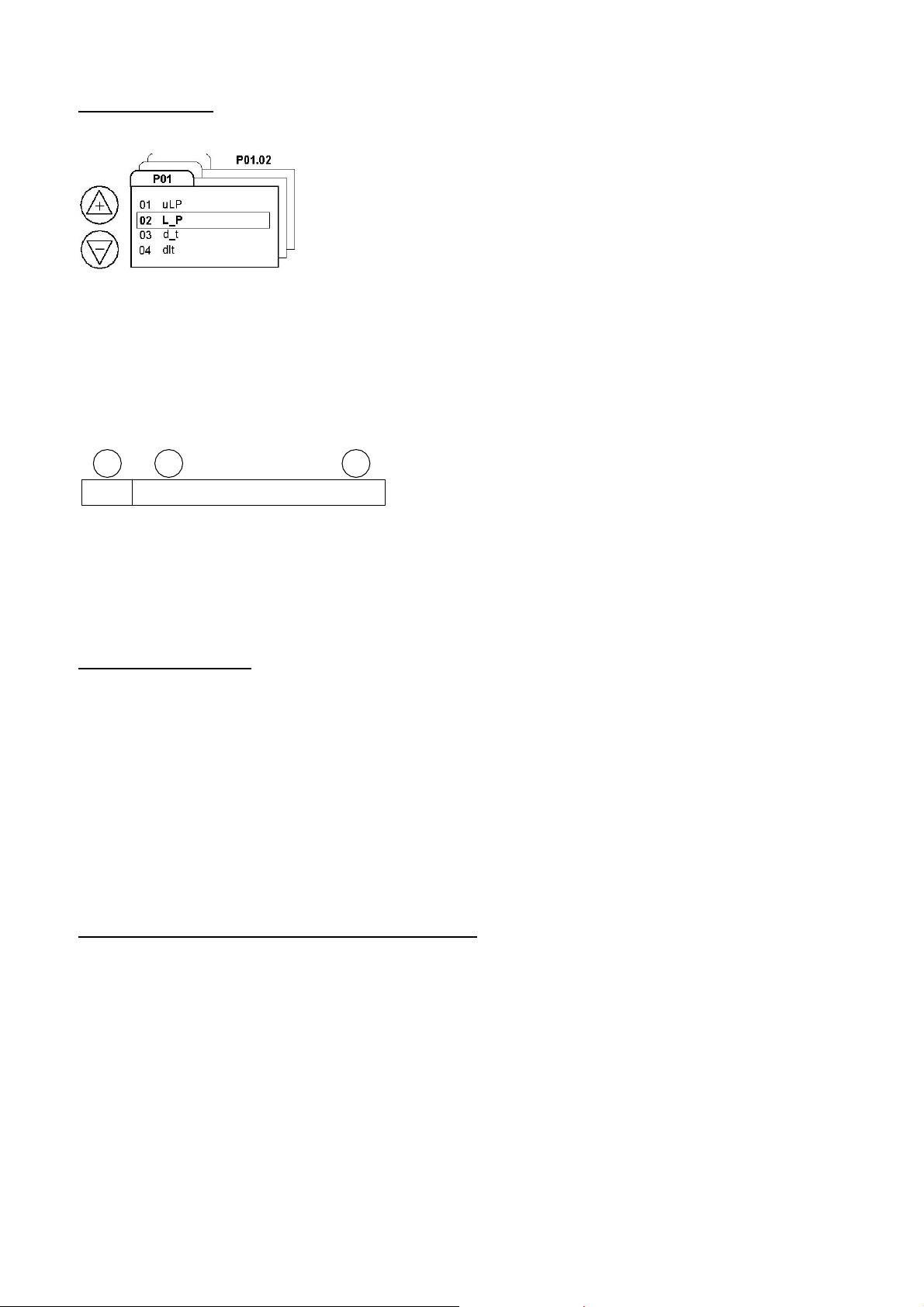
The menu structure of a controller has menu pages that contain a number of menu page ‘items’.
example menu and items
For example: menu pages P00, P01, P02 > P’n’.
Menu page P00 is the normal running list of display items that can be accessed and viewed on the controller displ ay without
access code. These items are ‘read only’ and consist of status, hours run and other general control or monitoring value (s).
Menu pages other than P00 are setup and configuration items that require an ‘access code’ when accessing the items on
the controller display.
Each menu page has a list of items that are referenced ‘1, 2, 3 > ‘n’.
a b c
P01
For example, a menu reference of P01.02 “AB” refers to menu item ‘2’ of menu page P01.
Each menu page item reference also has a two or three alphanumeric character item identification that is displayed by the
controller. With a menu reference the controller manual can be examined to determine the exact function, definition, scope
and limits for the specified item value.
Items that do not have a ‘Menu’ reference are general controller status or menu page P00 items.
‘ADV’ ADVISE FUNCTION
The ‘Advise’ function is a special type of ‘Get’ function. Each ‘Advise’ function item has an equivale nt ‘Get’ function; both
functions will provide a similar result.
Controllers on a Multi485 network will routinely broadcast key value and status specific data to all other controllers on the
network. This information is used, for example, by a system management unit for systems monitoring and control functions.
A SMG Box will automatically capture, store and continuously update these information items for each controller on the
network. Adv are Routine network broadcasts that occur every 2 seconds. Th transmission of this data consumes no
network bandwidth. (The maximum recommended request rate is 1 request every 2 seconds.)
This facility provides a method of retrieving ‘Adv’ data items directly from the SMG Box resulting in a faster response time
for information requests from a master. The method also has the advantage of reducing the amount of data traffic on the
Multi485 network enabling system management controllers to perform there functions without potential communication
delays. For this reason MODBUS ‘Adv’ functions are preferable to ‘Get’ functions when implemented on a Multi485 network
that consists of a system management controller with multiple machine controllers.
‘ADV’ ADVISE FUNCTION – SINGLE ITEM FORMAT OPTION
Controllers or units on a Multi485 network routinely broadcast general status and key per formance information. The SMG
Box will capture and store each ‘Broadcast’ detected. The Gateway ‘Broadcast’ registers will always contain the latest
‘broadcast’ information for each controller or unit on the Multi485 network. When a Modbus ‘Adv’ request is made the SMG
Box will respond immediately with information from it’s own ‘Broadcast’ registers for the unit addr ess specified. This function
reduces network activity and enables a faster Modbus response to commonly requested data.
A standard ‘Advise’ function defined in the ‘MODBUS Table’ will show the entire ‘broadcast’ being returned as a response.
The table will define for each ‘name’ item where in the returned data message the actual requ ested data can be found. The
‘master’ must then extract the required data from the returned data message. This method is very efficient as the master
can extract all ‘broadcast’ data from the single returned data message without the need to perform multiple requests for
each individual data item contained in a single slave controller ‘broadcast’ message.
01.02 AB
10
Page 11
Some ‘master’ devices may not be equipped with the necessary data message memory to handle a large message of many
bytes or have the ability to extract multiple data items from a single data message item. In this instance an alternativ e
‘Advise’ function request method can be implemented.If the ‘Advise’ items of a ‘MODBUS Table’ are examined it will be
seen that the ‘Register Address’ for each individual ‘Advise’ item contained in a single slave controller ‘broadcast’ message
will have the same start address (Register Address). If the entire ‘broadcast’ data message is 7 registers (14 bytes) in length
and only the 2nd register (2 bytes) of item data is required, it is possible to specify a ‘Register Address’ that is 2 bytes higher
(skip the first 2 bytes of the broadcast data message) with a ‘Register Length’ that is consistent with the required item data
length. This will instruct the MODBUS Gateway to extract the 2 bytes of required item data from the entire broadcast data
message and only return the required 2 bytes of data as a response. Using this method an ‘Advise’ fu nction can be handled
by a ‘master’ in exactly the same way as a ‘Get’ function.
For Example: (AdvDeliveryPressure):
The ‘broadcast’ of an example slave controller may be 6 bytes of data (3 registers) in length starting at register address
location ‘F000’ Hex. The 1st byte (byte 0) is 8bits coded status, the 2nd byte (byte 1) is 8bits status flags which together
form a single 16bit status register (1st register). The 3rd and 4th bytes (byte 2 and byte 3) are a single16bit register (2nd
register) containing a ‘delivery pressure’ value. The 5th and 6th b ytes (byte 4 and byte 5) are a single 16bit register (3rd
register) containing a ‘delivery temperature’ value. From an example ‘MODBUS Table’ it may be seen that the ‘Register
Address’ for all four of these separate ‘Adv’ items is ‘F000 Hex’ (the start address of the entire ‘Broadcast’ message that
contains the data specified).
An entire ‘Broadcast’ message may, for example, contain 3 registers (6 bytes) of data. For a particular item the ‘Modbus
Table’ may show the ‘start address’ for the entire broadcast to be ‘F000’ with a length of 3 registers (6 bytes). The Modbus
Table will indicate that the required data is 2 bytes long (number of data bytes) starting at the 2nd byte of data in the entire
broadcast (start location of data bytes).
Name AdvDeliveryPressure
Modbus Function 03
Modbus Register Address F000 (start address of entire Broadcast message)
Modbus Register Length 0003 (length of entire Broadcast message)
Coding Number of data bytes = 2 (length of AdvDeliveryPressure data)
Start location of data bytes = 2 (the 2 data bytes of the AdvDeliveryPressure data item
start at byte 2 in the Broadcast message = bytes 2 and 3 of the message)
Data Conversion Type = PSI
Master Request Message “01 03 F000 00 03 36CB” (36CB = CRC check sum)
Slave Answer Message “01 03 06 09 00 00 65 00 A8 304D” (304D = CRC)
Coding = PSI ‘00 65’Hex = 101 decimal = 101 psi
Register addresses shown are examples only
Status Register
Delivery
Pressure
Delivery
Temperature
Slave Address Function Code
Number of Data
Bytes to Follow
DATA
1st Register byte
0 byte 1
DATA
2nd Register
byte 2 byte 3
DATA
3rd Register byte
4 byte 5
CRC Check Sum
01 03 06 09 00 00 65 00 A8 30 4D
F000 F001 F002
Message Data
11
Page 12
If only the ‘delivery pressure’ (AdvDeliveryPressure) data value is required a new ‘Advise’ req uest message format can be
constructed from the Modbus Table definition:
Name AdvDeliveryPressure
Modbus Function 03
Modbus Register Address F001 (start at the second regi ster, byte 2, of the Broadcast)
Modbus Register Length 0001 (only return one register, 2 bytes, of data)
Using the new ‘Advise’ message format the SMG Box will return only the 2nd Broadcast message register (2 bytes)
containing the ‘delivery pressure’ data value.
Master Request Message “01 03 F001 0001 E6CA” (E6CA = CRC check sum)
Slave Answer Message “01 03 02 00 65 786F” (786F = CRC check sum)
Coding = PSI ’00 6 5’Hex = 101 decimal = 101 psi
Status Register
Delivery
Pressure
Delivery
Temperature
Modbus Register Address F000
Modbus Register Length 0003
Slave Address Function Code
Number of Data
Bytes to Follow
DATA
1st Register byte
0 byte 1
01 03 06 09 00 00 65 00 A8 30 4D
DATA
2nd Register
byte 2 byte 3
DATA
3rd Register byte
4 byte 5
CRC Check Sum
F000 F001 F002
Number of Data
Bytes to Follow
Modbus Register Address F001
Modbus Register Length 0001
Slave Address Function Code
01 03 02 00 65 78 6F
It is only possible to manipulate a Modbus message format using ‘registers’ (1 register = 2 bytes = 1 word = 16bits); it is
not possible to manipulate addresses or register lengths to a single byte of data. At least one register (2 bytes) of data must
be specified even if only one byte of information is required. The ‘master’ must extract the required byte of data from the
returned message.
The data type (the definition of the returned data) may be different when using an ‘Advise’ function than it is when using
a ‘Get’ function for the same information. The ‘delivery pressure’ returned by an ‘Advise’ function will be 2 bytes in length
and will represent pressure as an integer value in ‘psi’ units (PSI). The ‘delivery pressure’ returned by a ‘Get’ function may,
for example, be 4 bytes (2 registers) in length and represent a 32bit signed integer value in miliBar units (mBAR). Always
check the item ‘Coding’ definition to establish the data definition type.
Register addresses shown are examples only
‘CMD’ COMMAND FUNCTION
A ‘Command’ function will instruct the ‘slave’ controller or unit to execute a pre-defined action or process. With a command
type message the content of the ‘message data’ from the ‘master’ must always be the same value as the ‘lower byte’ of the
command register address. For example: if the command item ‘Register Address’ = 3302 then the ‘data’ value must be ’00
02’ Hex.
Slave Address Function Code Start Address
Number of
Registers To Be
Set
Number of Bytes
of Data
DATA
DATA
2nd Register
byte 2 byte 3
CRC Check Sum
CRC Check Sum
01 10 33 02 00 01 02 00 02 25 70
It is the act of setting the specified register in the ‘slave’ controller with the defined ‘data’ value that initiates the action or
process. An incorrect ‘data’ value will result in an exception response. If the ‘command’ is accepted the ‘slave’ will answer
with a normal ‘Set’ register response. If the slave is unable to execute the command it will give a code ‘04’ exception
response.
12
Page 13

Example:
Using a command function item to set the specified item register to the correct value, the ‘slave’ controller is instructed to
perform the defined action or process. In the case of a ‘CmdStart’ item, for example, the ‘slave’ controller is instructed to
start the machine. The implementation of a ‘Cmd’ function message by the ‘master’ is identical to a ‘Set’ function message;
both operations use function code ‘10 Hex’ to write data to a slave controller register.
Name CmdStart
Modbus Function 10
Modbus Register Address 3300
Modbus Register Length 0001
Coding Number of data bytes = 1
CmdStart (to slave at address ‘01’ Hex)
Master Command Message “01 10 3300 0001 02 0000 A553” (A553 = CRC check sum)
Slave Answer Message “01 10 3300 0001 0E8D” if start command executed or “01 90 04 4D C3” exception
response if not executed, ‘90’ = repeat of ‘10’ function code with MSB set to ‘1’ and ‘04’
= exception error code.
Register addresses shown are examples only
Names that begin with CMD are Non-routine. This data must be written to the device. (The maximum recommended
request rate is 2 requests per second up to 32 words per request.)
‘GET’ FUNCTION
Using the MODBUS Table a read data (Get) function message can be constructed:
Name GetDeliveryPressure Modbus
Function 03
Modbus Register Address 4006
Modbus Register Length 0002
Coding Number of data bytes = 4
Data Conversion Type = mBAR
GetDeliveryPressure (request to slave at address ‘01’ Hex)
Master Request Message “01 03 400 6 0002 31CA” (31CA = CRC check sum)
Slave Answer Message “01 03 04 00 00 1B 58 F139” (F139 = CRC check sum)
Coding = mBAR 1B 58Hex = 7000 decimal = 7000 miliBar (7.0 bar)
Register addresses shown are examples only
Note: Names that begin with Get are Non-routine. This data must be requested from the device. (The maximum
recommended request rate is 2 requests per second up to 32 words per request.)
‘SET’ FUNCTION
Using the MODBUS Table a write data (Set) function message can be constructed:
Name SetLoadPressure Modbus
Function 10
Modbus Register Address 4018
Modbus Register Length 0002
Coding Number of data bytes = 4
SetLoadPressure (to slave at address ‘01’ Hex)
Master Write Message “01 10 4018 0002 04 0000 1B58 C9CC” (C9CC = CRC)
Slave Answer Message “01 10 4018 0002 D40F” (D40F = CRC check sum)
Coding = mBAR 0000 1B58Hex = 7000 decimal = 7000 miliBar (7.0 bar)
Register addresses shown are examples only
Names that begin with Set are Non-routine. This data must be written to the device. (The maximum recommended
request rate is 2 requests per second up to 32 words per request.)
Data Conversion Type = mBAR
13
Page 14

DATA CODING DEFINITIONS:
Definitions for ‘data units’ and ‘data conversion types’ are listed for each ‘item’ in the “MODBUS Table” document.
All ‘data’ values are ‘whole’ numbers (integers); decimal places are not permitted in MODBUS data messages.
All ‘data’ values are unsigned (always positive) unless otherwise stated. Values specified as ‘SIGNED’ in the MODBUS
Table can be negative in accordance to the standard data conventio n for ‘sign ed’ number values.
DATA TYPES
Each standard definition will start with a “key” word that defines the data type:-
The following are selected examples; data types not included below are detaile d in individual ‘Modbus Tables’
Type Description
Coded a decimal value that has a defined definition; see the ‘Coded’ lists in
the ‘MODBUS Table’ for value definitions
Value a ‘whole’ number or value in the specified units
Pressure a ‘whole’ number defining a pressure in the specified units
Temperature a ‘whole’ number defining a temperature in the specified units
Time a ‘whole’ number defining a time period in the specified units
Electrical a ‘whole’ number defining a volt, amp, power, or speed value in the
specified units
Clock Clock values are relevant to real time clock functions; for example
pressure schedules. These ‘whole number’ unsigned values are
‘packaged’ multiple values and must be interpreted as follows.
Clock Data Type Coding
HH_MM 1) Divide the value by 60 = Hours (0 to 23)
2) The remainder (modulus) = Minutes (0 to 59)
Example for a value of ‘1050’
Hours = 1050 / 60 = 17.5 = 17 Hours
Minutes = remainder = 30 = 30 Minutes
Time = 17:30 (5:30pm)
D_HH_MM 1) Divide the value by 10000 = Day (1 = Monday, 7 = Sunday)
2) Divide the remainder (modulus) by 60 = Hours (0 to 23)
3) The remainder (modulus) = Minutes
Example for a value of ‘31050’
Day = 31050 / 10000 = 3.105 = 3 = Wednesday
Hours = = remainder / 60 = 17.5 = 17 Hours
Minutes = remainder = 30 = 30 Minutes
Day/Time = Wednesday 17:30 (5:30pm)
YYYY_DD_MO 1) Divide the value by 10000 = Year
2) Divide the remainder (modulus) by 100 = Day (1 to 31)
3) The remainder (modulus) = Month (1 to 12)
Example for a value of ‘20051605’
Year = 20051605 / 10000 = 2005.1605 = Year 2005
Day = remainder / 100 = 16.05 = Day 16
Month = remainder = 5 = Month 5
Date = 16th May 2005
14
Page 15
DATA UNITS
The ‘MODBUS Table’ will define the ‘data units’ for each item. Data unit definitions are specified in the ‘M ODBUS Table’ as
a separate list; for example:
The following are selected examples; data types not included below are detailed in the ‘Modbus Tables’
Value
The engineering units will differ dependant on unit set-up or item definition.
PSI
BAR
FAH
CEL
HRS
%
BOOLEAN
BINARY
The value must be interpreted in terms of each ‘bit’ as a set of sixteen Boolean (0 or 1) flags. These values
are compressor related or I/O Box Input related. For compressor related items the least significant bit (Bit 0)
represents compressor 1. For unit inputs the least significant bit (Bit 0) generally represents input 1.
The number is the value in the specified engineering units
Pressure in ‘psi’
Pressure in ‘Bar’
Temperature in oF
Temperature in oC
Hours
Percentage 0 to 100
The number will be 0 or greater than 0, (Boolean: 0 = False, 1 = True)
The number represents a 16bit (two byte) binary value of 16bit flags.
16 bit Register
1st Byte (byte 0) 2nd Byte (byte 1)
15141312111098 76543210
Bit
MSB
The example illustrates the bit pattern for a value of ’00 81 Hex’. This value is interpr eted as a ‘true’ condition with respect to
the item definition for compressors 1 and 8. If the ‘item’ definition is ‘Compressors Running’ then com pressors 1 and 8 are in
a ‘running’ condition.
00000000 10000001
Compressor 8 Compressor 1
LSB
15
Page 16
The example illustrates the bit pattern for a value of "1A 04 C2 01" Hex. A reference to ‘Bit 18’ equates to bit ‘2’ of byte ‘1’ in
the answer data message. If the ‘bit’ is ‘1’ then the condition is ‘TRUE’.
2nd Register1st Register
1st Byte (byte 0) 2nd Byte (byte 1) 3rd Byte (byte 2) 4th Byte (byte 3)
3130292827262524 2322212019181716 15141312111098 76543210
Bit
00011010 00000100 11000010 00000000
MSB
BIT ‘n’
Note: The LSB (least significant bit) of a register or byte is regarded as Bit 0(zero)
A Boolean (true/false) can be established from examining the specified ‘bit’ of the
16bit register. If the item specifies ‘Bit 4’ then the 4th bit should be examined:
LSB
16 bit Register
1st Byte (byte 0) 2nd Byte (by te 1)
15141312111098 76543210
Bit
MSB
00011010 10010001
LSB
AND
00000000 00010000
EQUALS
00000000 00010000
= 16 Decimal (Condition is TRUE)
The 4th bit of a register can be extracted by ‘masking’ the register content with “10 Hex”; if the resulting value is greater than
0(zero) then the condition is ‘True’, if the result is 0(zero) then the condition is ‘False’.
Decimal Places:
Numbers with decimal places (eg 20.55) are not permissible in MODBUS data transfer – all numbers must be integer
‘whole’ numbers. To provide ‘decimal place’ accuracy some data values are multiplied by 10, 100 or 1000 and transmitted
as a ‘whole’ number (integer). In this instance the ‘Data Units’ will specify that the number represe nts a value to one or more
decimal places.
For example: PERCENT_DP2 = Percent to 2 decimal places
“2055” divided by 100 = 20.55%
If the ‘Data Units’ specifies “to 1 decimal place”, divide the number by 10 to convert to the correct engineering units. If the
‘Data Units’ specifies “to 2 decimal places”, divide the number by 100; if 3 decimal places divide by 1000.
16
Page 17
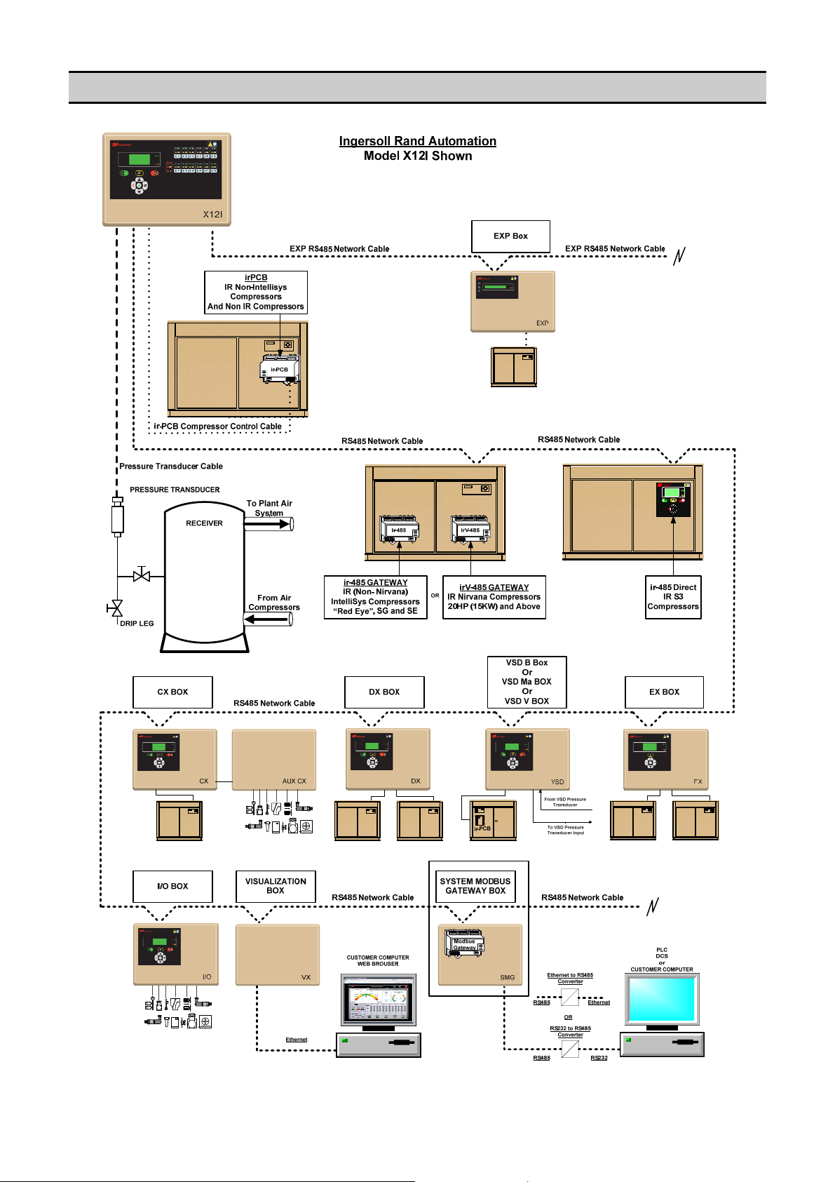
SECTION 6 - X-SERIES AIR SYSTEM
Note: example only; systems will differ from installation to installation
17
Page 18
SMG BOX
For Remote Monitoring/Control of X-Series Units and Boxes. The SMG Box provides a RS485 Modbus connection to the
X8I Automation System. A system will only contain one SMG Box.
GENERAL X-SERIES SYSTEM COMPONENTS
The following Components can be monitored by the SMG Box.
X8I Series Controller or X12I Series Controller: Automation System Unit
Monitors and controls the air compressors, all general system and air compressor related information is governed and
available from this unit. A system will only contain one X-Series Automation System controller.
EX Box: Extension to the X-Series Unit
For connection to remote compressor(s) or other specialized compressor integration. All common air compressor status
information is sent to, and available from, the X-Series system management unit. A system may contain multiple EX Boxes.
I/O Box: Monitoring/Control of Auxiliary Equipment and/or Sensors
For monitoring and/or control of auxiliary compressed air equipment (for exam ple: dryer, auto drain, filtration differential,
isolation valves, cooling water towers/pumps, ventilation) or sensors (for example: pressure, pressure differential, dewpoint,
air flow, temperature). A system may contain multiple IO Boxes.
VSD Box: Extension to the X-Series Unit
For connection to variable speed compressor(s) or other specialized compressor integration. All common air compressor
status information is sent to, and available from, the X-Series system management unit. A system may contain multiple VSD
Boxes.
CX Box: Extension to the X-Series Unit
For connection to non-Ingersoll Rand air compressors that are not equipped with any accessible means of remote
connectivity. All common air compressor status information is sent to, and available from, the X-Series system management
unit. A system may contain multiple CX Boxes.
DX Box: Extension to the X-Series Unit
For connection to two fixed speed online/offline air compressors to be seen as one compressor by the X8I or X12I. All
common air compressor status information is sent to, and available from, the X-Series system management unit. A system
may contain multiple DX Boxes.
ir-485 Gateway / irV-485 Gateway
For connection to all Ingersoll Rand Intellisys based compressors. All common air compressor status information is sent to,
and available from, the X-Series system management unit. A system may contain multiple Gateways.
ir-485 Direct
For connection to all Ingersoll Rand R Series (S3) based compressors. All common air compressor status information is
sent to, and available from, the X-Series system management unit. A system may contain multiple R series compressors.
18
Page 19

X-SERIES NETWORK ADDRESSES
UNIT
X8I or X12I
EX, VSD B / mA / V, CX, DX, ir485 / irV485, S3
(As It Relates To The Compressor Number Assigned)
Compressor 1 1 (01)
Compressor 2 2 (02)
Compressor 3 3 (03)
Compressor 4 4 (04)
Compressor 5 5 (05)
Compressor 6 6 (06)
Compressor 7 7 (07)
Compressor 8 8 (08)
Compressor 9 9 (09) X12I ONLY
Compressor 10 10 (0A) X12I ONLY
Compressor 11 11 (0B) X12I ONLY
Compressor 12 12 (0C) X12I ONLY
I/O
I/O Box 1 105(69)
I/O Box 2 112(70)
I/O Box 3 106(6A) X12I ONLY
I/O Box 4 107(6B) X12I ONLY
I/O Box 5 108(6C) X12I ONLY
I/O Box 6 109(6D) X12I ONLY
I/O Box 7 110(6E) X12I ONLY
I/O Box 8 111(6F) X12I ONLY
I/O Box 9 113(71) X12I ONLY
I/O Box 10 114(72) X12I ONLY
I/O Box 11 115(73) X12I ONLY
I/O Box 12 116(74) X12I ONLY
Note: I/O Unit 2 address (70Hex) is intentionally out of sequence; this is not a print error.
DECIMAL (HEX) ADDRESS NOTES
101(65)
COMMUNICATION LINK
To Interface with a X-Series product that is equipped with a Multi485 enabled network port, or to interface with multiple XSeries products operating on a single Multi485 system network, a SMG Box unit is required. The SMG Box forms the
interface between the Multi485 protocol and MODBUS RTU master/slave communications link.
SMG Box connectivity is implemented using a two-wire RS485 industry standard commun ications link operating in point-topoint, master-slave mode. In use the SMG Box is transparent and each X-Series system unit is accessible using individual
system device addresses.
Polarity of the two MODBUS RS485 wires (L1+ or ‘A’ and L2- or ‘B’) is important; reversal will inhibit communications
and result in error.
MODBUS TIMING
The SMG will handle ONE (1) MODBUS request at a time from the customer’s port. The maximum recommended request
rate is 2 requests per second. When a MODBUS request is received for any device connected to the XI Automation System,
that request will be forwarded to the device between sequencer broadcasts and the response from the device will then be
relayed back to the customer’s port. If a second MODBUS command is sent before the first command has been responded
to, the second command will be ignored.
RS485 MODBUS SERIAL DATA FORMAT
The SMG supports only the RTU transmission mode. The user must configure their serial port communication parameters
(baud rate, parity mode, etc.) during configuration to match those of the SMG Box. The SMG Box port operates with an
asynchronous serial data format:
SMG Communication Parameters:
Data Bits: 8
Parity: None
Stop Bit: 1
Baud Rate: 9600
8-N-1-9600
19
Page 20

SECTION 7 – IO BOX MODBUS RTU DEFINITIONS
Name : AdvAnaIn0Value
Modbus Function : 03
Modbus Register Address : F400
Modbus Register Length : 0009
Coding : Number of data bytes = 2
: Start location of data bytes = 0
Data Conversion Type = SIGNED,NUMERIC
Name : AdvAnaIn1Value
Modbus Function : 03
Modbus Register Address : F400
Modbus Register Length : 0009
Coding : Number of data bytes = 2
: Start location of data bytes = 2
Data Conversion Type = SIGNED,NUMERIC
Name : AdvAnaIn2Value
Modbus Function : 03
Modbus Register Address : F400
Modbus Register Length : 0009
Coding : Number of data bytes = 2
: Start location of data bytes = 4
Data Conversion Type = SIGNED,NUMERIC
Name : AdvAnaIn3Value
Modbus Function : 03
Modbus Register Address : F400
Modbus Register Length : 0009
Coding : Number of data bytes = 2
: Start location of data bytes = 6
Data Conversion Type = SIGNED,NUMERIC
Name : AdvDigInReading
Modbus Function : 03
Modbus Register Address : F400
Modbus Register Length : 0009
Coding : Number of data bytes = 2
: Start location of data bytes = 16
Name : AdvAnaInStateAlm
Modbus Function : 03
Modbus Register Address : F420
Modbus Register Length : 0007
Coding : Number of data bytes = 1
: Start location of data bytes = 0
Name : AdvAnaInStateErr
Modbus Function : 03
Modbus Register Address : F420
Modbus Register Length : 0007
Coding : Number of data bytes = 1
: Start location of data bytes = 1
20
Page 21

Name : AdvAnaInStateSrel
Modbus Function : 03
Modbus Register Address : F420
Modbus Register Length : 0007
Coding : Number of data bytes = 1
: Start location of data bytes = 2
Name : AdvDigInStateAlm
Modbus Function : 03
Modbus Register Address : F420
Modbus Register Length : 0007
Coding : Number of data bytes = 2
: Start location of data bytes = 3
Name : AdvDigInStateErr
Modbus Function : 03
Modbus Register Address : F420
Modbus Register Length : 0007
Coding : Number of data bytes = 2
: Start location of data bytes = 5
Name : AdvDigInStateSrel
Modbus Function : 03
Modbus Register Address : F420
Modbus Register Length : 0007
Coding : Number of data bytes = 2
: Start location of data bytes = 7
Name : AdvDigOut
Modbus Function : 03
Modbus Register Address : F420
Modbus Register Length : 0007
Coding : Number of data bytes = 2
: Start location of data bytes = 9
Name : AdvAnaInS1Ai1
Modbus Function : 03
Modbus Register Address : F420
Modbus Register Length : 0007
Coding : Number of data bytes = 2
: Start location of data bytes = 11
21
Page 22

Name : GetSoftwareVersionIdString
Modbus Function : 03
Modbus Register Address : 3400
Modbus Register Length : 0003
Coding : Number of data bytes = 6
Data Conversion Type = STRING
Name : GetSoftwareVersionRevString
Modbus Function : 03
Modbus Register Address : 3403
Modbus Register Length : 0003
Coding : Number of data bytes = 6
Data Conversion Type = STRING
Name : CmdResetCom
Modbus Function : 10
Modbus Register Address : 3306
Modbus Register Length : 0001
Coding : Number of data bytes = 1
Name : CmdResetModule
Modbus Function : 10
Modbus Register Address : 3308
Modbus Register Length : 0001
Coding : Number of data bytes = 1
Name : CmdResetCounters
Modbus Function : 10
Modbus Register Address : 3309
Modbus Register Length : 0001
Coding : Number of data bytes = 1
Name : GetAnalogInput1
Modbus Function : 03
Modbus Register Address : 3100
Modbus Register Length : 0001
Coding : Number of data bytes = 2
Data Units = ADSTEPS
Name : GetAnalogInput2
Modbus Function : 03
Modbus Register Address : 3101
Modbus Register Length : 0001
Coding : Number of data bytes = 2
Data Units = ADSTEPS
Name : GetAnalogInput3
Modbus Function : 03
Modbus Register Address : 3102
Modbus Register Length : 0001
Coding : Number of data bytes = 2
Data Units = ADSTEPS
Name : GetAnalogOutput1
Modbus Function : 03
Modbus Register Address : 310C
Modbus Register Length : 0001
Coding : Number of data bytes = 2
Data Units = ADSTEPS
22
Page 23

Name : GetDigitalInputs
Modbus Function : 03
Modbus Register Address : 310E
Modbus Register Length : 0001
Coding : Number of data bytes = 2
Data Units = BINARY
bitvalue = 0 = digital input INACTIVE
bitvalue = 1 = digital input ACTIVE
bit = Name (Config, Delay in ms)
0 = EMERGENCY_STOP (None, 0)
1 = (undefined)
2 = (undefined)
3 = (undefined)
4 = (undefined)
5 = (undefined)
6 = (undefined)
7 = (undefined)
Name : GetDigitalInputsConfiguration
Modbus Function : 03
Modbus Register Address : 310F
Modbus Register Length : 0001
Coding : Number of data bytes = 2
Data Units = BINARY
bitvalue = 0 = digital input NO
bitvalue = 1 = digital input NC
bit = Name
0 = EMERGENCY_STOP
1 =
2 =
3 =
4 =
5 =
6 =
7 =
Name : GetDigitalInput1PulseCounts
Modbus Function : 03
Modbus Register Address : 3110
Modbus Register Length : 0001
Coding : Number of data bytes = 2
Data Units = ULONG_VAL
Name : GetDigitalInput2PulseCounts
Modbus Function : 03
Modbus Register Address : 3111
Modbus Register Length : 0001
Coding : Number of data bytes = 2
Data Units = ULONG_VAL
Name : GetDigitalInput3PulseCounts
Modbus Function : 03
Modbus Register Address : 3112
Modbus Register Length : 0001
Coding : Number of data bytes = 2
Data Units = ULONG_VAL
Name : GetDigitalInput4PulseCounts
Modbus Function : 03
Modbus Register Address : 3113
Modbus Register Length : 0001
Coding : Number of data bytes = 2
Data Units = ULONG_VAL
23
Page 24

Name : GetDigitalInput5PulseCounts
Modbus Function : 03
Modbus Register Address : 3114
Modbus Register Length : 0001
Coding : Number of data bytes = 2
Data Units = ULONG_VAL
Name : GetDigitalInput6PulseCounts
Modbus Function : 03
Modbus Register Address : 3115
Modbus Register Length : 0001
Coding : Number of data bytes = 2
Data Units = ULONG_VAL
Name : GetDigitalInput7PulseCounts
Modbus Function : 03
Modbus Register Address : 3116
Modbus Register Length : 0001
Coding : Number of data bytes = 2
Data Units = ULONG_VAL
Name : GetDigitalInput8PulseCounts
Modbus Function : 03
Modbus Register Address : 3117
Modbus Register Length : 0001
Coding : Number of data bytes = 2
Data Units = ULONG_VAL
Name : GetDigitalOutputs
Modbus Function : 03
Modbus Register Address : 3118
Modbus Register Length : 0001
Coding : Number of data bytes = 2
Data Units = BINARY
bitvalue = 0 = digital output OFF
bitvalue = 1 = digital output ON
bit = Name
0 = RELAY_1
1 = RELAY_2
2 = RELAY_3
3 = RELAY_4
4 = RELAY_5
5 = RELAY_6
Name : GetAnaIn0AvgValue
Modbus Function : 03
Modbus Register Address : 4004
Modbus Register Length : 0002
Coding : Number of data bytes = 4
Data Units = RT_UPDATED
Name : GetAnaIn1AvgValue
Modbus Function : 03
Modbus Register Address : 4006
Modbus Register Length : 0002
Coding : Number of data bytes = 4
Data Units = RT_UPDATED
Name : GetAnaIn2AvgValue
Modbus Function : 03
Modbus Register Address : 4008
Modbus Register Length : 0002
Coding : Number of data bytes = 4
Data Units = RT_UPDATED
24
Page 25

Name : GetAnaIn3AvgValue
Modbus Function : 03
Modbus Register Address : 400A
Modbus Register Length : 0002
Coding : Number of data bytes = 4
Data Units = RT_UPDATED
Name : GetDigIn0Value
Modbus Function : 03
Modbus Register Address : 400C
Modbus Register Length : 0002
Coding : Number of data bytes = 4
Data Units = ON_OFF
Name : GetDigIn1Value
Modbus Function : 03
Modbus Register Address : 400E
Modbus Register Length : 0002
Coding : Number of data bytes = 4
Data Units = ON_OFF
Name : GetDigIn2Value
Modbus Function : 03
Modbus Register Address : 4010
Modbus Register Length : 0002
Coding : Number of data bytes = 4
Data Units = ON_OFF
Name : GetDigIn3Value
Modbus Function : 03
Modbus Register Address : 4012
Modbus Register Length : 0002
Coding : Number of data bytes = 4
Data Units = ON_OFF
Name : GetDigIn4Value
Modbus Function : 03
Modbus Register Address : 4014
Modbus Register Length : 0002
Coding : Number of data bytes = 4
Data Units = ON_OFF
Name : GetDigIn5Value
Modbus Function : 03
Modbus Register Address : 4016
Modbus Register Length : 0002
Coding : Number of data bytes = 4
Data Units = ON_OFF
Name : GetDigIn6Value
Modbus Function : 03
Modbus Register Address : 4018
Modbus Register Length : 0002
Coding : Number of data bytes = 4
Data Units = ON_OFF
Name : GetDigIn7Value
Modbus Function : 03
Modbus Register Address : 401A
Modbus Register Length : 0002
Coding : Number of data bytes = 4
Data Units = ON_OFF
25
Page 26

Name : GetDigOut0State
Modbus Function : 03
Modbus Register Address : 401C
Modbus Register Length : 0002
Coding : Number of data bytes = 4
Data Units = ON_OFF
Name : GetDigOut1State
Modbus Function : 03
Modbus Register Address : 401E
Modbus Register Length : 0002
Coding : Number of data bytes = 4
Data Units = ON_OFF
Name : GetDigOut2State
Modbus Function : 03
Modbus Register Address : 4020
Modbus Register Length : 0002
Coding : Number of data bytes = 4
Data Units = ON_OFF
Name : GetDigOut3State
Modbus Function : 03
Modbus Register Address : 4022
Modbus Register Length : 0002
Coding : Number of data bytes = 4
Data Units = ON_OFF
Name : GetDigOut4State
Modbus Function : 03
Modbus Register Address : 4024
Modbus Register Length : 0002
Coding : Number of data bytes = 4
Data Units = ON_OFF
Name : GetDigOut5State
Modbus Function : 03
Modbus Register Address : 4026
Modbus Register Length : 0002
Coding : Number of data bytes = 4
Data Units = ON_OFF
Name : GetPressureS1Ai1Detect
Modbus Function : 03
Modbus Register Address : 402C
Modbus Register Length : 0002
Coding : Number of data bytes = 4
Data Units = UCHAR_VAL
Menu = S01.02 'PD'
Name : SetPressureS1Ai1Detect
Modbus Function : 10
Modbus Register Address : 402C
Modbus Register Length : 0002
Coding : Number of data bytes = 4
Data Units = UCHAR_VAL
Menu = S01.02 'PD'
26
Page 27

Name : GetPressureS1Ai1Offset
Modbus Function : 03
Modbus Register Address : 402E
Modbus Register Length : 0002
Coding : Number of data bytes = 4
Data Conversion Type = SIGNED,NUMERIC
Data Units = mBAR
Menu = S01.03 'Po'
Name : SetPressureS1Ai1Offset
Modbus Function : 10
Modbus Register Address : 402E
Modbus Register Length : 0002
Coding : Number of data bytes = 4
Data Conversion Type = SIGNED,NUMERIC
Data Units = mBAR
Menu = S01.03 'Po'
Name : GetPressureS1Ai1Range
Modbus Function : 03
Modbus Register Address : 4030
Modbus Register Length : 0002
Coding : Number of data bytes = 4
Data Units = mBAR
Menu = S01.04 'Pr'
Name : SetPressureS1Ai1Range
Modbus Function : 10
Modbus Register Address : 4030
Modbus Register Length : 0002
Coding : Number of data bytes = 4
Data Units = mBAR
Menu = S01.04 'Pr'
Name : GetPressureS1Ai1Unit
Modbus Function : 03
Modbus Register Address : 4032
Modbus Register Length : 0002
Coding : Number of data bytes = 4
Data Conversion Type = CODED,P_UNIT
Conversion table for CODED,P_UNIT can be found at the end of this
document
Data Units = LONG_VAL
Menu = S01.05 'P>'
Name : SetPressureS1Ai1Unit
Modbus Function : 10
Modbus Register Address : 4032
Modbus Register Length : 0002
Coding : Number of data bytes = 4
Data Conversion Type = CODED,P_UNIT
Conversion table for CODED,P_UNIT can be found at the end of this
document
Data Units = LONG_VAL
Menu = S01.05 'P>'
Name : GetP00DefaultItem
Modbus Function : 03
Modbus Register Address : 4034
Modbus Register Length : 0002
Coding : Number of data bytes = 4
Data Units = P00_ITEM
Menu = S01.06 'ID'
27
Page 28

Name : SetP00DefaultItem
Modbus Function : 10
Modbus Register Address : 4034
Modbus Register Length : 0002
Coding : Number of data bytes = 4
Data Units = P00_ITEM
Menu = S01.06 'ID'
Name : GetResetPulseCountersEnable
Modbus Function : 03
Modbus Register Address : 4036
Modbus Register Length : 0002
Coding : Number of data bytes = 4
Data Units = UCHAR_VAL
Menu = S01.07 'RP'
Name : SetResetPulseCountersEnable
Modbus Function : 10
Modbus Register Address : 4036
Modbus Register Length : 0002
Coding : Number of data bytes = 4
Data Units = UCHAR_VAL
Menu = S01.07 'RP'
Name : SetDigInConfig1Type
Modbus Function : 10
Modbus Register Address : 4038
Modbus Register Length : 0002
Coding : Number of data bytes = 4
Data Units = DI_TYPE
Name : SetDigInConfig1FaultFunc
Modbus Function : 10
Modbus Register Address : 403A
Modbus Register Length : 0002
Coding : Number of data bytes = 4
Data Units = FAULT_FUNC
Name : SetDigInConfig1Delay
Modbus Function : 10
Modbus Register Address : 403C
Modbus Register Length : 0002
Coding : Number of data bytes = 4
Data Units = mSEC
Name : SetDigInConfig1Reset
Modbus Function : 10
Modbus Register Address : 403E
Modbus Register Length : 0002
Coding : Number of data bytes = 4
Data Units = ULONG_VAL
Name : GetDigInConfig1Type
Modbus Function : 03
Modbus Register Address : 4038
Modbus Register Length : 0002
Coding : Number of data bytes = 4
Data Conversion Type = CODED,DI_TYPE
Conversion table for CODED,DI_TYPE can be found at the end of this
document
Data Units = ULONG_VAL
28
Page 29

Name : GetDigInConfig1FaultFunc
Modbus Function : 03
Modbus Register Address : 403A
Modbus Register Length : 0002
Coding : Number of data bytes = 4
Data Conversion Type = CODED,FAULT_FUNC
Conversion table for CODED,FAULT_FUNC can be found at the end of this
document
Data Units = ULONG_VAL
Name : GetDigInConfig1Delay
Modbus Function : 03
Modbus Register Address : 403C
Modbus Register Length : 0002
Coding : Number of data bytes = 4
Data Units = mSEC
Name : GetDigInConfig1Reset
Modbus Function : 03
Modbus Register Address : 403E
Modbus Register Length : 0002
Coding : Number of data bytes = 4
Data Units = ULONG_VAL
Name : SetDigInConfig2Type
Modbus Function : 10
Modbus Register Address : 4040
Modbus Register Length : 0002
Coding : Number of data bytes = 4
Data Units = DI_TYPE
Name : SetDigInConfig2FaultFunc
Modbus Function : 10
Modbus Register Address : 4042
Modbus Register Length : 0002
Coding : Number of data bytes = 4
Data Units = FAULT_FUNC
Name : SetDigInConfig2Delay
Modbus Function : 10
Modbus Register Address : 4044
Modbus Register Length : 0002
Coding : Number of data bytes = 4
Data Units = mSEC
Name : SetDigInConfig2Reset
Modbus Function : 10
Modbus Register Address : 4046
Modbus Register Length : 0002
Coding : Number of data bytes = 4
Data Units = ULONG_VAL
Name : GetDigInConfig2Type
Modbus Function : 03
Modbus Register Address : 4040
Modbus Register Length : 0002
Coding : Number of data bytes = 4
Data Conversion Type = CODED,DI_TYPE
Conversion table for CODED,DI_TYPE can be found at the end of this
document
Data Units = ULONG_VAL
29
Page 30

Name : GetDigInConfig2FaultFunc
Modbus Function : 03
Modbus Register Address : 4042
Modbus Register Length : 0002
Coding : Number of data bytes = 4
Data Conversion Type = CODED,FAULT_FUNC
Conversion table for CODED,FAULT_FUNC can be found at the end of this
document
Data Units = ULONG_VAL
Name : GetDigInConfig2Delay
Modbus Function : 03
Modbus Register Address : 4044
Modbus Register Length : 0002
Coding : Number of data bytes = 4
Data Units = mSEC
Name : GetDigInConfig2Reset
Modbus Function : 03
Modbus Register Address : 4046
Modbus Register Length : 0002
Coding : Number of data bytes = 4
Data Units = ULONG_VAL
Name : SetDigInConfig3Type
Modbus Function : 10
Modbus Register Address : 4048
Modbus Register Length : 0002
Coding : Number of data bytes = 4
Data Units = DI_TYPE
Name : SetDigInConfig3FaultFunc
Modbus Function : 10
Modbus Register Address : 404A
Modbus Register Length : 0002
Coding : Number of data bytes = 4
Data Units = FAULT_FUNC
Name : SetDigInConfig3Delay
Modbus Function : 10
Modbus Register Address : 404C
Modbus Register Length : 0002
Coding : Number of data bytes = 4
Data Units = mSEC
Name : SetDigInConfig3Reset
Modbus Function : 10
Modbus Register Address : 404E
Modbus Register Length : 0002
Coding : Number of data bytes = 4
Data Units = ULONG_VAL
Name : GetDigInConfig3Type
Modbus Function : 03
Modbus Register Address : 4048
Modbus Register Length : 0002
Coding : Number of data bytes = 4
Data Conversion Type = CODED,DI_TYPE
Conversion table for CODED,DI_TYPE can be found at the end of this
document
Data Units = ULONG_VAL
30
Page 31

Name : GetDigInConfig3FaultFunc
Modbus Function : 03
Modbus Register Address : 404A
Modbus Register Length : 0002
Coding : Number of data bytes = 4
Data Conversion Type = CODED,FAULT_FUNC
Conversion table for CODED,FAULT_FUNC can be found at the end of this
document
Data Units = ULONG_VAL
Name : GetDigInConfig3Delay
Modbus Function : 03
Modbus Register Address : 404C
Modbus Register Length : 0002
Coding : Number of data bytes = 4
Data Units = mSEC
Name : GetDigInConfig3Reset
Modbus Function : 03
Modbus Register Address : 404E
Modbus Register Length : 0002
Coding : Number of data bytes = 4
Data Units = ULONG_VAL
Name : SetDigInConfig4Type
Modbus Function : 10
Modbus Register Address : 4050
Modbus Register Length : 0002
Coding : Number of data bytes = 4
Data Units = DI_TYPE
Name : SetDigInConfig4FaultFunc
Modbus Function : 10
Modbus Register Address : 4052
Modbus Register Length : 0002
Coding : Number of data bytes = 4
Data Units = FAULT_FUNC
Name : SetDigInConfig4Delay
Modbus Function : 10
Modbus Register Address : 4054
Modbus Register Length : 0002
Coding : Number of data bytes = 4
Data Units = mSEC
Name : SetDigInConfig4Reset
Modbus Function : 10
Modbus Register Address : 4056
Modbus Register Length : 0002
Coding : Number of data bytes = 4
Data Units = ULONG_VAL
Name : GetDigInConfig4Type
Modbus Function : 03
Modbus Register Address : 4050
Modbus Register Length : 0002
Coding : Number of data bytes = 4
Data Conversion Type = CODED,DI_TYPE
Conversion table for CODED,DI_TYPE can be found at the end of this
document
Data Units = ULONG_VAL
31
Page 32

Name : GetDigInConfig4FaultFunc
Modbus Function : 03
Modbus Register Address : 4052
Modbus Register Length : 0002
Coding : Number of data bytes = 4
Data Conversion Type = CODED,FAULT_FUNC
Conversion table for CODED,FAULT_FUNC can be found at the end of this
document
Data Units = ULONG_VAL
Name : GetDigInConfig4Delay
Modbus Function : 03
Modbus Register Address : 4054
Modbus Register Length : 0002
Coding : Number of data bytes = 4
Data Units = mSEC
Name : GetDigInConfig4Reset
Modbus Function : 03
Modbus Register Address : 4056
Modbus Register Length : 0002
Coding : Number of data bytes = 4
Data Units = ULONG_VAL
Name : SetDigInConfig5Type
Modbus Function : 10
Modbus Register Address : 4058
Modbus Register Length : 0002
Coding : Number of data bytes = 4
Data Units = DI_TYPE
Name : SetDigInConfig5FaultFunc
Modbus Function : 10
Modbus Register Address : 405A
Modbus Register Length : 0002
Coding : Number of data bytes = 4
Data Units = FAULT_FUNC
Name : SetDigInConfig5Delay
Modbus Function : 10
Modbus Register Address : 405C
Modbus Register Length : 0002
Coding : Number of data bytes = 4
Data Units = mSEC
Name : SetDigInConfig5Reset
Modbus Function : 10
Modbus Register Address : 405E
Modbus Register Length : 0002
Coding : Number of data bytes = 4
Data Units = ULONG_VAL
Name : GetDigInConfig5Type
Modbus Function : 03
Modbus Register Address : 4058
Modbus Register Length : 0002
Coding : Number of data bytes = 4
Data Conversion Type = CODED,DI_TYPE
Conversion table for CODED,DI_TYPE can be found at the end of this
document
Data Units = ULONG_VAL
32
Page 33

Name : GetDigInConfig5FaultFunc
Modbus Function : 03
Modbus Register Address : 405A
Modbus Register Length : 0002
Coding : Number of data bytes = 4
Data Conversion Type = CODED,FAULT_FUNC
Conversion table for CODED,FAULT_FUNC can be found at the end of this
document
Data Units = ULONG_VAL
Name : GetDigInConfig5Delay
Modbus Function : 03
Modbus Register Address : 405C
Modbus Register Length : 0002
Coding : Number of data bytes = 4
Data Units = mSEC
Name : GetDigInConfig5Reset
Modbus Function : 03
Modbus Register Address : 405E
Modbus Register Length : 0002
Coding : Number of data bytes = 4
Data Units = ULONG_VAL
Name : SetDigInConfig6Type
Modbus Function : 10
Modbus Register Address : 4060
Modbus Register Length : 0002
Coding : Number of data bytes = 4
Data Units = DI_TYPE
Name : SetDigInConfig6FaultFunc
Modbus Function : 10
Modbus Register Address : 4062
Modbus Register Length : 0002
Coding : Number of data bytes = 4
Data Units = FAULT_FUNC
Name : SetDigInConfig6Delay
Modbus Function : 10
Modbus Register Address : 4064
Modbus Register Length : 0002
Coding : Number of data bytes = 4
Data Units = mSEC
Name : SetDigInConfig6Reset
Modbus Function : 10
Modbus Register Address : 4066
Modbus Register Length : 0002
Coding : Number of data bytes = 4
Data Units = ULONG_VAL
Name : GetDigInConfig6Type
Modbus Function : 03
Modbus Register Address : 4060
Modbus Register Length : 0002
Coding : Number of data bytes = 4
Data Conversion Type = CODED,DI_TYPE
Conversion table for CODED,DI_TYPE can be found at the end of this
document
Data Units = ULONG_VAL
33
Page 34

Name : GetDigInConfig6FaultFunc
Modbus Function : 03
Modbus Register Address : 4062
Modbus Register Length : 0002
Coding : Number of data bytes = 4
Data Conversion Type = CODED,FAULT_FUNC
Conversion table for CODED,FAULT_FUNC can be found at the end of this
document
Data Units = ULONG_VAL
Name : GetDigInConfig6Delay
Modbus Function : 03
Modbus Register Address : 4064
Modbus Register Length : 0002
Coding : Number of data bytes = 4
Data Units = mSEC
Name : GetDigInConfig6Reset
Modbus Function : 03
Modbus Register Address : 4066
Modbus Register Length : 0002
Coding : Number of data bytes = 4
Data Units = ULONG_VAL
Name : SetDigInConfig7Type
Modbus Function : 10
Modbus Register Address : 4068
Modbus Register Length : 0002
Coding : Number of data bytes = 4
Data Units = DI_TYPE
Name : SetDigInConfig7FaultFunc
Modbus Function : 10
Modbus Register Address : 406A
Modbus Register Length : 0002
Coding : Number of data bytes = 4
Data Units = FAULT_FUNC
Name : SetDigInConfig7Delay
Modbus Function : 10
Modbus Register Address : 406C
Modbus Register Length : 0002
Coding : Number of data bytes = 4
Data Units = mSEC
Name : SetDigInConfig7Reset
Modbus Function : 10
Modbus Register Address : 406E
Modbus Register Length : 0002
Coding : Number of data bytes = 4
Data Units = ULONG_VAL
Name : GetDigInConfig7Type
Modbus Function : 03
Modbus Register Address : 4068
Modbus Register Length : 0002
Coding : Number of data bytes = 4
Data Conversion Type = CODED,DI_TYPE
Conversion table for CODED,DI_TYPE can be found at the end of this
document
Data Units = ULONG_VAL
34
Page 35

Name : GetDigInConfig7FaultFunc
Modbus Function : 03
Modbus Register Address : 406A
Modbus Register Length : 0002
Coding : Number of data bytes = 4
Data Conversion Type = CODED,FAULT_FUNC
Conversion table for CODED,FAULT_FUNC can be found at the end of this
document
Data Units = ULONG_VAL
Name : GetDigInConfig7Delay
Modbus Function : 03
Modbus Register Address : 406C
Modbus Register Length : 0002
Coding : Number of data bytes = 4
Data Units = mSEC
Name : GetDigInConfig7Reset
Modbus Function : 03
Modbus Register Address : 406E
Modbus Register Length : 0002
Coding : Number of data bytes = 4
Data Units = ULONG_VAL
Name : SetDigInConfig8Type
Modbus Function : 10
Modbus Register Address : 4070
Modbus Register Length : 0002
Coding : Number of data bytes = 4
Data Units = DI_TYPE
Name : SetDigInConfig8FaultFunc
Modbus Function : 10
Modbus Register Address : 4072
Modbus Register Length : 0002
Coding : Number of data bytes = 4
Data Units = FAULT_FUNC
Name : SetDigInConfig8Delay
Modbus Function : 10
Modbus Register Address : 4074
Modbus Register Length : 0002
Coding : Number of data bytes = 4
Data Units = mSEC
Name : SetDigInConfig8Reset
Modbus Function : 10
Modbus Register Address : 4076
Modbus Register Length : 0002
Coding : Number of data bytes = 4
Data Units = ULONG_VAL
Name : GetDigInConfig8Type
Modbus Function : 03
Modbus Register Address : 4070
Modbus Register Length : 0002
Coding : Number of data bytes = 4
Data Conversion Type = CODED,DI_TYPE
Conversion table for CODED,DI_TYPE can be found at the end of this
document
Data Units = ULONG_VAL
35
Page 36

Name : GetDigInConfig8FaultFunc
Modbus Function : 03
Modbus Register Address : 4072
Modbus Register Length : 0002
Coding : Number of data bytes = 4
Data Conversion Type = CODED,FAULT_FUNC
Conversion table for CODED,FAULT_FUNC can be found at the end of this
document
Data Units = ULONG_VAL
Name : GetDigInConfig8Delay
Modbus Function : 03
Modbus Register Address : 4074
Modbus Register Length : 0002
Coding : Number of data bytes = 4
Data Units = mSEC
Name : GetDigInConfig8Reset
Modbus Function : 03
Modbus Register Address : 4076
Modbus Register Length : 0002
Coding : Number of data bytes = 4
Data Units = ULONG_VAL
Name : SetAnaInConfig1Type
Modbus Function : 10
Modbus Register Address : 4080
Modbus Register Length : 0002
Coding : Number of data bytes = 4
Data Units = ACM_TYPE
Name : SetAnaInConfig1Unit
Modbus Function : 10
Modbus Register Address : 4082
Modbus Register Length : 0002
Coding : Number of data bytes = 4
Data Units = AI_UNIT
Name : SetAnaInConfig1ValueOffset
Modbus Function : 10
Modbus Register Address : 4084
Modbus Register Length : 0002
Coding : Number of data bytes = 4
Data Units = ULONG_VAL
Name : SetAnaInConfig1ValueRange
Modbus Function : 10
Modbus Register Address : 4086
Modbus Register Length : 0002
Coding : Number of data bytes = 4
Data Units = ULONG_VAL
Name : SetAnaInConfig1DisplFunc
Modbus Function : 10
Modbus Register Address : 4088
Modbus Register Length : 0002
Coding : Number of data bytes = 4
Data Units = DISPL_FUNC
36
Page 37

Name : SetAnaInConfig1FaultFuncH
Modbus Function : 10
Modbus Register Address : 408A
Modbus Register Length : 0002
Coding : Number of data bytes = 4
Data Units = ULONG_VAL
Name : SetAnaInConfig1FaultFuncL
Modbus Function : 10
Modbus Register Address : 408C
Modbus Register Length : 0002
Coding : Number of data bytes = 4
Data Units = ULONG_VAL
Name : SetAnaInConfig1FaultFunc
Modbus Function : 10
Modbus Register Address : 408E
Modbus Register Length : 0002
Coding : Number of data bytes = 4
Data Units = FAULT_FUNC
Name : SetAnaInConfig1FaultInhibit
Modbus Function : 10
Modbus Register Address : 4090
Modbus Register Length : 0002
Coding : Number of data bytes = 4
Data Units = ULONG_VAL
Name : SetAnaInConfig1Delay
Modbus Function : 10
Modbus Register Address : 4092
Modbus Register Length : 0002
Coding : Number of data bytes = 4
Data Units = mSEC
Name : SetAnaInConfig1Reset
Modbus Function : 10
Modbus Register Address : 4094
Modbus Register Length : 0002
Coding : Number of data bytes = 4
Data Units = ULONG_VAL
Name : GetAnaInConfig1Type
Modbus Function : 03
Modbus Register Address : 4080
Modbus Register Length : 0002
Coding : Number of data bytes = 4
Data Conversion Type = CODED,ACM_TYPE
Conversion table for CODED,ACM_TYPE can be found at the end of this
document
Data Units = ULONG_VAL
Name : GetAnaInConfig1Unit
Modbus Function : 03
Modbus Register Address : 4082
Modbus Register Length : 0002
Coding : Number of data bytes = 4
Data Conversion Type = CODED,AI_UNIT
Conversion table for CODED,AI_UNIT can be found at the end of this
document
Data Units = ULONG_VAL
37
Page 38

Name : GetAnaInConfig1ValueOffset
Modbus Function : 03
Modbus Register Address : 4084
Modbus Register Length : 0002
Coding : Number of data bytes = 4
Data Units = ULONG_VAL
Name : GetAnaInConfig1ValueRange
Modbus Function : 03
Modbus Register Address : 4086
Modbus Register Length : 0002
Coding : Number of data bytes = 4
Data Units = ULONG_VAL
Name : GetAnaInConfig1DisplFunc
Modbus Function : 03
Modbus Register Address : 4088
Modbus Register Length : 0002
Coding : Number of data bytes = 4
Data Conversion Type = CODED,DISPL_FUNC
Conversion table for CODED,DISPL_FUNC can be found at the end of this
document
Data Units = ULONG_VAL
Name : GetAnaInConfig1FaultFuncH
Modbus Function : 03
Modbus Register Address : 408A
Modbus Register Length : 0002
Coding : Number of data bytes = 4
Data Units = ULONG_VAL
Name : GetAnaInConfig1FaultFuncL
Modbus Function : 03
Modbus Register Address : 408C
Modbus Register Length : 0002
Coding : Number of data bytes = 4
Data Units = ULONG_VAL
Name : GetAnaInConfig1FaultFunc
Modbus Function : 03
Modbus Register Address : 408E
Modbus Register Length : 0002
Coding : Number of data bytes = 4
Data Conversion Type = CODED,FAULT_FUNC
Conversion table for CODED,FAULT_FUNC can be found at the end of this
document
Data Units = ULONG_VAL
Name : GetAnaInConfig1FaultInhibit
Modbus Function : 03
Modbus Register Address : 4090
Modbus Register Length : 0002
Coding : Number of data bytes = 4
Data Units = ULONG_VAL
Name : GetAnaInConfig1Delay
Modbus Function : 03
Modbus Register Address : 4092
Modbus Register Length : 0002
Coding : Number of data bytes = 4
Data Units = mSEC
38
Page 39

Name : GetAnaInConfig1Reset
Modbus Function : 03
Modbus Register Address : 4094
Modbus Register Length : 0002
Coding : Number of data bytes = 4
Data Units = ULONG_VAL
Name : SetAnaInConfig2Type
Modbus Function : 10
Modbus Register Address : 4096
Modbus Register Length : 0002
Coding : Number of data bytes = 4
Data Units = ACM_TYPE
Name : SetAnaInConfig2Unit
Modbus Function : 10
Modbus Register Address : 4098
Modbus Register Length : 0002
Coding : Number of data bytes = 4
Data Units = AI_UNIT
Name : SetAnaInConfig2ValueOffset
Modbus Function : 10
Modbus Register Address : 409A
Modbus Register Length : 0002
Coding : Number of data bytes = 4
Data Units = ULONG_VAL
Name : SetAnaInConfig2ValueRange
Modbus Function : 10
Modbus Register Address : 409C
Modbus Register Length : 0002
Coding : Number of data bytes = 4
Data Units = ULONG_VAL
Name : SetAnaInConfig2DisplFunc
Modbus Function : 10
Modbus Register Address : 409E
Modbus Register Length : 0002
Coding : Number of data bytes = 4
Data Units = DISPL_FUNC
Name : SetAnaInConfig2FaultFuncH
Modbus Function : 10
Modbus Register Address : 40A0
Modbus Register Length : 0002
Coding : Number of data bytes = 4
Data Units = ULONG_VAL
Name : SetAnaInConfig2FaultFuncL
Modbus Function : 10
Modbus Register Address : 40A2
Modbus Register Length : 0002
Coding : Number of data bytes = 4
Data Units = ULONG_VAL
Name : SetAnaInConfig2FaultFunc
Modbus Function : 10
Modbus Register Address : 40A4
Modbus Register Length : 0002
Coding : Number of data bytes = 4
Data Units = FAULT_FUNC
39
Page 40

Name : SetAnaInConfig2FaultInhibit
Modbus Function : 10
Modbus Register Address : 40A6
Modbus Register Length : 0002
Coding : Number of data bytes = 4
Data Units = ULONG_VAL
Name : SetAnaInConfig2Delay
Modbus Function : 10
Modbus Register Address : 40A8
Modbus Register Length : 0002
Coding : Number of data bytes = 4
Data Units = mSEC
Name : SetAnaInConfig2Reset
Modbus Function : 10
Modbus Register Address : 40AA
Modbus Register Length : 0002
Coding : Number of data bytes = 4
Data Units = ULONG_VAL
Name : GetAnaInConfig2Type
Modbus Function : 03
Modbus Register Address : 4096
Modbus Register Length : 0002
Coding : Number of data bytes = 4
Data Conversion Type = CODED,ACM_TYPE
Conversion table for CODED,ACM_TYPE can be found at the end of this
document
Data Units = ULONG_VAL
Name : GetAnaInConfig2Unit
Modbus Function : 03
Modbus Register Address : 4098
Modbus Register Length : 0002
Coding : Number of data bytes = 4
Data Conversion Type = CODED,AI_UNIT
Conversion table for CODED,AI_UNIT can be found at the end of this
document
Data Units = ULONG_VAL
Name : GetAnaInConfig2ValueOffset
Modbus Function : 03
Modbus Register Address : 409A
Modbus Register Length : 0002
Coding : Number of data bytes = 4
Data Units = ULONG_VAL
Name : GetAnaInConfig2ValueRange
Modbus Function : 03
Modbus Register Address : 409C
Modbus Register Length : 0002
Coding : Number of data bytes = 4
Data Units = ULONG_VAL
Name : GetAnaInConfig2DisplFunc
Modbus Function : 03
Modbus Register Address : 409E
Modbus Register Length : 0002
Coding : Number of data bytes = 4
Data Conversion Type = CODED,DISPL_FUNC
Conversion table for CODED,DISPL_FUNC can be found at the end of this
document
Data Units = ULONG_VAL
40
Page 41

Name : GetAnaInConfig2FaultFuncH
Modbus Function : 03
Modbus Register Address : 40A0
Modbus Register Length : 0002
Coding : Number of data bytes = 4
Data Units = ULONG_VAL
Name : GetAnaInConfig2FaultFuncL
Modbus Function : 03
Modbus Register Address : 40A2
Modbus Register Length : 0002
Coding : Number of data bytes = 4
Data Units = ULONG_VAL
Name : GetAnaInConfig2FaultFunc
Modbus Function : 03
Modbus Register Address : 40A4
Modbus Register Length : 0002
Coding : Number of data bytes = 4
Data Conversion Type = CODED,FAULT_FUNC
Conversion table for CODED,FAULT_FUNC can be found at the end of this
document
Data Units = ULONG_VAL
Name : GetAnaInConfig2FaultInhibit
Modbus Function : 03
Modbus Register Address : 40A6
Modbus Register Length : 0002
Coding : Number of data bytes = 4
Data Units = ULONG_VAL
Name : GetAnaInConfig2Delay
Modbus Function : 03
Modbus Register Address : 40A8
Modbus Register Length : 0002
Coding : Number of data bytes = 4
Data Units = mSEC
Name : GetAnaInConfig2Reset
Modbus Function : 03
Modbus Register Address : 40AA
Modbus Register Length : 0002
Coding : Number of data bytes = 4
Data Units = ULONG_VAL
Name : SetAnaInConfig3Type
Modbus Function : 10
Modbus Register Address : 40AC
Modbus Register Length : 0002
Coding : Number of data bytes = 4
Data Units = ACM_TYPE
Name : SetAnaInConfig3Unit
Modbus Function : 10
Modbus Register Address : 40AE
Modbus Register Length : 0002
Coding : Number of data bytes = 4
Data Units = AI_UNIT
41
Page 42

Name : SetAnaInConfig3ValueOffset
Modbus Function : 10
Modbus Register Address : 40B0
Modbus Register Length : 0002
Coding : Number of data bytes = 4
Data Units = ULONG_VAL
Name : SetAnaInConfig3ValueRange
Modbus Function : 10
Modbus Register Address : 40B2
Modbus Register Length : 0002
Coding : Number of data bytes = 4
Data Units = ULONG_VAL
Name : SetAnaInConfig3DisplFunc
Modbus Function : 10
Modbus Register Address : 40B4
Modbus Register Length : 0002
Coding : Number of data bytes = 4
Data Units = DISPL_FUNC
Name : SetAnaInConfig3FaultFuncH
Modbus Function : 10
Modbus Register Address : 40B6
Modbus Register Length : 0002
Coding : Number of data bytes = 4
Data Units = ULONG_VAL
Name : SetAnaInConfig3FaultFuncL
Modbus Function : 10
Modbus Register Address : 40B8
Modbus Register Length : 0002
Coding : Number of data bytes = 4
Data Units = ULONG_VAL
Name : SetAnaInConfig3FaultFunc
Modbus Function : 10
Modbus Register Address : 40BA
Modbus Register Length : 0002
Coding : Number of data bytes = 4
Data Units = FAULT_FUNC
Name : SetAnaInConfig3FaultInhibit
Modbus Function : 10
Modbus Register Address : 40BC
Modbus Register Length : 0002
Coding : Number of data bytes = 4
Data Units = ULONG_VAL
Name : SetAnaInConfig3Delay
Modbus Function : 10
Modbus Register Address : 40BE
Modbus Register Length : 0002
Coding : Number of data bytes = 4
Data Units = mSEC
Name : SetAnaInConfig3Reset
Modbus Function : 10
Modbus Register Address : 40C0
Modbus Register Length : 0002
Coding : Number of data bytes = 4
Data Units = ULONG_VAL
42
Page 43

Name : GetAnaInConfig3Type
Modbus Function : 03
Modbus Register Address : 40AC
Modbus Register Length : 0002
Coding : Number of data bytes = 4
Data Conversion Type = CODED,ACM_TYPE
Conversion table for CODED,ACM_TYPE can be found at the end of this
document
Data Units = ULONG_VAL
Name : GetAnaInConfig3Unit
Modbus Function : 03
Modbus Register Address : 40AE
Modbus Register Length : 0002
Coding : Number of data bytes = 4
Data Conversion Type = CODED,AI_UNIT
Conversion table for CODED,AI_UNIT can be found at the end of this
document
Data Units = ULONG_VAL
Name : GetAnaInConfig3ValueOffset
Modbus Function : 03
Modbus Register Address : 40B0
Modbus Register Length : 0002
Coding : Number of data bytes = 4
Data Units = ULONG_VAL
Name : GetAnaInConfig3ValueRange
Modbus Function : 03
Modbus Register Address : 40B2
Modbus Register Length : 0002
Coding : Number of data bytes = 4
Data Units = ULONG_VAL
Name : GetAnaInConfig3DisplFunc
Modbus Function : 03
Modbus Register Address : 40B4
Modbus Register Length : 0002
Coding : Number of data bytes = 4
Data Conversion Type = CODED,DISPL_FUNC
Conversion table for CODED,DISPL_FUNC can be found at the end of this
document
Data Units = ULONG_VAL
Name : GetAnaInConfig3FaultFuncH
Modbus Function : 03
Modbus Register Address : 40B6
Modbus Register Length : 0002
Coding : Number of data bytes = 4
Data Units = ULONG_VAL
Name : GetAnaInConfig3FaultFuncL
Modbus Function : 03
Modbus Register Address : 40B8
Modbus Register Length : 0002
Coding : Number of data bytes = 4
Data Units = ULONG_VAL
43
Page 44

Name : GetAnaInConfig3FaultFunc
Modbus Function : 03
Modbus Register Address : 40BA
Modbus Register Length : 0002
Coding : Number of data bytes = 4
Data Conversion Type = CODED,FAULT_FUNC
Conversion table for CODED,FAULT_FUNC can be found at the end of this
document
Data Units = ULONG_VAL
Name : GetAnaInConfig3FaultInhibit
Modbus Function : 03
Modbus Register Address : 40BC
Modbus Register Length : 0002
Coding : Number of data bytes = 4
Data Units = ULONG_VAL
Name : GetAnaInConfig3Delay
Modbus Function : 03
Modbus Register Address : 40BE
Modbus Register Length : 0002
Coding : Number of data bytes = 4
Data Units = mSEC
Name : GetAnaInConfig3Reset
Modbus Function : 03
Modbus Register Address : 40C0
Modbus Register Length : 0002
Coding : Number of data bytes = 4
Data Units = ULONG_VAL
Name : SetAnaInConfig4Type
Modbus Function : 10
Modbus Register Address : 40C2
Modbus Register Length : 0002
Coding : Number of data bytes = 4
Data Units = ACM_TYPE
Name : SetAnaInConfig4Unit
Modbus Function : 10
Modbus Register Address : 40C4
Modbus Register Length : 0002
Coding : Number of data bytes = 4
Data Units = AI_UNIT
Name : SetAnaInConfig4ValueOffset
Modbus Function : 10
Modbus Register Address : 40C6
Modbus Register Length : 0002
Coding : Number of data bytes = 4
Data Units = ULONG_VAL
Name : SetAnaInConfig4ValueRange
Modbus Function : 10
Modbus Register Address : 40C8
Modbus Register Length : 0002
Coding : Number of data bytes = 4
Data Units = ULONG_VAL
44
Page 45

Name : SetAnaInConfig4DisplFunc
Modbus Function : 10
Modbus Register Address : 40CA
Modbus Register Length : 0002
Coding : Number of data bytes = 4
Data Units = DISPL_FUNC
Name : SetAnaInConfig4FaultFuncH
Modbus Function : 10
Modbus Register Address : 40CC
Modbus Register Length : 0002
Coding : Number of data bytes = 4
Data Units = ULONG_VAL
Name : SetAnaInConfig4FaultFuncL
Modbus Function : 10
Modbus Register Address : 40CE
Modbus Register Length : 0002
Coding : Number of data bytes = 4
Data Units = ULONG_VAL
Name : SetAnaInConfig4FaultFunc
Modbus Function : 10
Modbus Register Address : 40D0
Modbus Register Length : 0002
Coding : Number of data bytes = 4
Data Units = FAULT_FUNC
Name : SetAnaInConfig4FaultInhibit
Modbus Function : 10
Modbus Register Address : 40D2
Modbus Register Length : 0002
Coding : Number of data bytes = 4
Data Units = ULONG_VAL
Name : SetAnaInConfig4Delay
Modbus Function : 10
Modbus Register Address : 40D4
Modbus Register Length : 0002
Coding : Number of data bytes = 4
Data Units = mSEC
Name : SetAnaInConfig4Reset
Modbus Function : 10
Modbus Register Address : 40D6
Modbus Register Length : 0002
Coding : Number of data bytes = 4
Data Units = ULONG_VAL
Name : GetAnaInConfig4Type
Modbus Function : 03
Modbus Register Address : 40C2
Modbus Register Length : 0002
Coding : Number of data bytes = 4
Data Conversion Type = CODED,ACM_TYPE
Conversion table for CODED,ACM_TYPE can be found at the end of this
document
Data Units = ULONG_VAL
45
Page 46

Name : GetAnaInConfig4Unit
Modbus Function : 03
Modbus Register Address : 40C4
Modbus Register Length : 0002
Coding : Number of data bytes = 4
Data Conversion Type = CODED,AI_UNIT
Conversion table for CODED,AI_UNIT can be found at the end of this
document
Data Units = ULONG_VAL
Name : GetAnaInConfig4ValueOffset
Modbus Function : 03
Modbus Register Address : 40C6
Modbus Register Length : 0002
Coding : Number of data bytes = 4
Data Units = ULONG_VAL
Name : GetAnaInConfig4ValueRange
Modbus Function : 03
Modbus Register Address : 40C8
Modbus Register Length : 0002
Coding : Number of data bytes = 4
Data Units = ULONG_VAL
Name : GetAnaInConfig4DisplFunc
Modbus Function : 03
Modbus Register Address : 40CA
Modbus Register Length : 0002
Coding : Number of data bytes = 4
Data Conversion Type = CODED,DISPL_FUNC
Conversion table for CODED,DISPL_FUNC can be found at the end of this
document
Data Units = ULONG_VAL
Name : GetAnaInConfig4FaultFuncH
Modbus Function : 03
Modbus Register Address : 40CC
Modbus Register Length : 0002
Coding : Number of data bytes = 4
Data Units = ULONG_VAL
Name : GetAnaInConfig4FaultFuncL
Modbus Function : 03
Modbus Register Address : 40CE
Modbus Register Length : 0002
Coding : Number of data bytes = 4
Data Units = ULONG_VAL
Name : GetAnaInConfig4FaultFunc
Modbus Function : 03
Modbus Register Address : 40D0
Modbus Register Length : 0002
Coding : Number of data bytes = 4
Data Conversion Type = CODED,FAULT_FUNC
Conversion table for CODED,FAULT_FUNC can be found at the end of this
document
Data Units = ULONG_VAL
Name : GetAnaInConfig4FaultInhibit
Modbus Function : 03
Modbus Register Address : 40D2
Modbus Register Length : 0002
Coding : Number of data bytes = 4
Data Units = ULONG_VAL
46
Page 47

Name : GetAnaInConfig4Delay
Modbus Function : 03
Modbus Register Address : 40D4
Modbus Register Length : 0002
Coding : Number of data bytes = 4
Data Units = mSEC
Name : GetAnaInConfig4Reset
Modbus Function : 03
Modbus Register Address : 40D6
Modbus Register Length : 0002
Coding : Number of data bytes = 4
Data Units = ULONG_VAL
Name : SetRelayConfig1Func1
Modbus Function : 10
Modbus Register Address : 40EE
Modbus Register Length : 0002
Coding : Number of data bytes = 4
Data Units = REL_FUNC
Name : SetRelayConfig1Func2
Modbus Function : 10
Modbus Register Address : 40F0
Modbus Register Length : 0002
Coding : Number of data bytes = 4
Data Units = REL_FUNC
Name : SetRelayConfig1FuncComb
Modbus Function : 10
Modbus Register Address : 40F2
Modbus Register Length : 0002
Coding : Number of data bytes = 4
Data Units = REL_FUNC_COMB
Name : SetRelayConfig1OnDelay
Modbus Function : 10
Modbus Register Address : 40F4
Modbus Register Length : 0002
Coding : Number of data bytes = 4
Data Units = mSEC
Name : SetRelayConfig1OffDelay
Modbus Function : 10
Modbus Register Address : 40F6
Modbus Register Length : 0002
Coding : Number of data bytes = 4
Data Units = mSEC
Name : SetRelayConfig1NormalState
Modbus Function : 10
Modbus Register Address : 40F8
Modbus Register Length : 0002
Coding : Number of data bytes = 4
Data Units = ON_OFF
Name : SetRelayConfig1FuncNcomState
Modbus Function : 10
Modbus Register Address : 40FA
Modbus Register Length : 0002
Coding : Number of data bytes = 4
Data Units = ON_OFF
47
Page 48

Name : GetRelayConfig1Func1
Modbus Function : 03
Modbus Register Address : 40EE
Modbus Register Length : 0002
Coding : Number of data bytes = 4
Data Units = ULONG_VAL
Name : GetRelayConfig1Func1Unit
Modbus Function : 03
Modbus Register Address : 40EF
Modbus Register Length : 0001
Coding : Number of data bytes = 1
: Start location of data byte = 1
Data Conversion Type = CODED,REL_FUNC_UNIT
Conversion table for CODED,REL_FUNC_UNIT can be found at the end of
this document
Data Units = UCHAR_VAL
Name : GetRelayConfig1Func1Source
Modbus Function : 03
Modbus Register Address : 40EF
Modbus Register Length : 0001
Coding : Number of data bytes = 1
: Start location of data byte = 0
Data Conversion Type = CODED,REL_FUNC_SOURCE
Conversion table for CODED,REL_FUNC_SOURCE can be found at the end
of this document
Data Units = UCHAR_VAL
Name : GetRelayConfig1Func1Id
Modbus Function : 03
Modbus Register Address : 40EE
Modbus Register Length : 0001
Coding : Number of data bytes = 1
: Start location of data byte = 1
Data Conversion Type = CODED,REL_FUNC_ID
Conversion table for CODED,REL_FUNC_ID can be found at the end of this
document
Data Units = UCHAR_VAL
Name : GetRelayConfig1Func1Remote
Modbus Function : 03
Modbus Register Address : 40EE
Modbus Register Length : 0001
Coding : Number of data bytes = 1
: Start location of data byte = 0
Data Units = ON_OFF
Name : GetRelayConfig1Func2
Modbus Function : 03
Modbus Register Address : 40F0
Modbus Register Length : 0002
Coding : Number of data bytes = 4
Data Units = ULONG_VAL
48
Page 49

Name : GetRelayConfig1Func2Unit
Modbus Function : 03
Modbus Register Address : 40F1
Modbus Register Length : 0001
Coding : Number of data bytes = 1
: Start location of data byte = 1
Data Conversion Type = CODED,REL_FUNC_UNIT
Conversion table for CODED,REL_FUNC_UNIT can be found at the end of
this document
Data Units = UCHAR_VAL
Name : GetRelayConfig1Func2Source
Modbus Function : 03
Modbus Register Address : 40F1
Modbus Register Length : 0001
Coding : Number of data bytes = 1
: Start location of data byte = 0
Data Conversion Type = CODED,REL_FUNC_SOURCE
Conversion table for CODED,REL_FUNC_SOURCE can be found at the end
of this document
Data Units = UCHAR_VAL
Name : GetRelayConfig1Func2Id
Modbus Function : 03
Modbus Register Address : 40F0
Modbus Register Length : 0001
Coding : Number of data bytes = 1
: Start location of data byte = 1
Data Conversion Type = CODED,REL_FUNC_ID
Conversion table for CODED,REL_FUNC_ID can be found at the end of this
document
Data Units = UCHAR_VAL
Name : GetRelayConfig1Func2Remote
Modbus Function : 03
Modbus Register Address : 40F0
Modbus Register Length : 0001
Coding : Number of data bytes = 1
: Start location of data byte = 0
Data Units = ON_OFF
Name : GetRelayConfig1FuncComb
Modbus Function : 03
Modbus Register Address : 40F2
Modbus Register Length : 0002
Coding : Number of data bytes = 4
Data Conversion Type = CODED,REL_FUNC_COMB
Conversion table for CODED,REL_FUNC_COMB can be found at the end of
this document
Data Units = ULONG_VAL
Name : GetRelayConfig1OnDelay
Modbus Function : 03
Modbus Register Address : 40F4
Modbus Register Length : 0002
Coding : Number of data bytes = 4
Data Units = mSEC
Name : GetRelayConfig1OffDelay
Modbus Function : 03
Modbus Register Address : 40F6
Modbus Register Length : 0002
Coding : Number of data bytes = 4
Data Units = mSEC
49
Page 50

Name : GetRelayConfig1NormalState
Modbus Function : 03
Modbus Register Address : 40F8
Modbus Register Length : 0002
Coding : Number of data bytes = 4
Data Units = ON_OFF
Name : GetRelayConfig1FuncNcomState
Modbus Function : 03
Modbus Register Address : 40FA
Modbus Register Length : 0002
Coding : Number of data bytes = 4
Data Units = ON_OFF
Name : SetRelayConfig2Func1
Modbus Function : 10
Modbus Register Address : 40FC
Modbus Register Length : 0002
Coding : Number of data bytes = 4
Data Units = REL_FUNC
Name : SetRelayConfig2Func2
Modbus Function : 10
Modbus Register Address : 40FE
Modbus Register Length : 0002
Coding : Number of data bytes = 4
Data Units = REL_FUNC
Name : SetRelayConfig2FuncComb
Modbus Function : 10
Modbus Register Address : 4100
Modbus Register Length : 0002
Coding : Number of data bytes = 4
Data Units = REL_FUNC_COMB
Name : SetRelayConfig2OnDelay
Modbus Function : 10
Modbus Register Address : 4102
Modbus Register Length : 0002
Coding : Number of data bytes = 4
Data Units = mSEC
Name : SetRelayConfig2OffDelay
Modbus Function : 10
Modbus Register Address : 4104
Modbus Register Length : 0002
Coding : Number of data bytes = 4
Data Units = mSEC
Name : SetRelayConfig2NormalState
Modbus Function : 10
Modbus Register Address : 4106
Modbus Register Length : 0002
Coding : Number of data bytes = 4
Data Units = ON_OFF
Name : SetRelayConfig2FuncNcomState
Modbus Function : 10
Modbus Register Address : 4108
Modbus Register Length : 0002
Coding : Number of data bytes = 4
Data Units = ON_OFF
50
Page 51

Name : GetRelayConfig2Func1
Modbus Function : 03
Modbus Register Address : 40FC
Modbus Register Length : 0002
Coding : Number of data bytes = 4
Data Units = ULONG_VAL
Name : GetRelayConfig2Func1Unit
Modbus Function : 03
Modbus Register Address : 40FD
Modbus Register Length : 0001
Coding : Number of data bytes = 1
: Start location of data byte = 1
Data Conversion Type = CODED,REL_FUNC_UNIT
Conversion table for CODED,REL_FUNC_UNIT can be found at the end of
this document
Data Units = UCHAR_VAL
Name : GetRelayConfig2Func1Source
Modbus Function : 03
Modbus Register Address : 40FD
Modbus Register Length : 0001
Coding : Number of data bytes = 1
: Start location of data byte = 0
Data Conversion Type = CODED,REL_FUNC_SOURCE
Conversion table for CODED,REL_FUNC_SOURCE can be found at the end
of this document
Data Units = UCHAR_VAL
Name : GetRelayConfig2Func1Id
Modbus Function : 03
Modbus Register Address : 40FC
Modbus Register Length : 0001
Coding : Number of data bytes = 1
: Start location of data byte = 1
Data Conversion Type = CODED,REL_FUNC_ID
Conversion table for CODED,REL_FUNC_ID can be found at the end of this
document
Data Units = UCHAR_VAL
Name : GetRelayConfig2Func1Remote
Modbus Function : 03
Modbus Register Address : 40FC
Modbus Register Length : 0001
Coding : Number of data bytes = 1
: Start location of data byte = 0
Data Units = ON_OFF
Name : GetRelayConfig2Func2
Modbus Function : 03
Modbus Register Address : 40FE
Modbus Register Length : 0002
Coding : Number of data bytes = 4
Data Units = ULONG_VAL
51
Page 52

Name : GetRelayConfig2Func2Unit
Modbus Function : 03
Modbus Register Address : 40FF
Modbus Register Length : 0001
Coding : Number of data bytes = 1
: Start location of data byte = 1
Data Conversion Type = CODED,REL_FUNC_UNIT
Conversion table for CODED,REL_FUNC_UNIT can be found at the end of
this document
Data Units = UCHAR_VAL
Name : GetRelayConfig2Func2Source
Modbus Function : 03
Modbus Register Address : 40FF
Modbus Register Length : 0001
Coding : Number of data bytes = 1
: Start location of data byte = 0
Data Conversion Type = CODED,REL_FUNC_SOURCE
Conversion table for CODED,REL_FUNC_SOURCE can be found at the end
of this document
Data Units = UCHAR_VAL
Name : GetRelayConfig2Func2Id
Modbus Function : 03
Modbus Register Address : 40FE
Modbus Register Length : 0001
Coding : Number of data bytes = 1
: Start location of data byte = 1
Data Conversion Type = CODED,REL_FUNC_ID
Conversion table for CODED,REL_FUNC_ID can be found at the end of this
document
Data Units = UCHAR_VAL
Name : GetRelayConfig2Func2Remote
Modbus Function : 03
Modbus Register Address : 40FE
Modbus Register Length : 0001
Coding : Number of data bytes = 1
: Start location of data byte = 0
Data Units = ON_OFF
Name : GetRelayConfig2FuncComb
Modbus Function : 03
Modbus Register Address : 4100
Modbus Register Length : 0002
Coding : Number of data bytes = 4
Data Conversion Type = CODED,REL_FUNC_COMB
Conversion table for CODED,REL_FUNC_COMB can be found at the end of
this document
Data Units = ULONG_VAL
Name : GetRelayConfig2OnDelay
Modbus Function : 03
Modbus Register Address : 4102
Modbus Register Length : 0002
Coding : Number of data bytes = 4
Data Units = mSEC
Name : GetRelayConfig2OffDelay
Modbus Function : 03
Modbus Register Address : 4104
Modbus Register Length : 0002
Coding : Number of data bytes = 4
Data Units = mSEC
52
Page 53

Name : GetRelayConfig2NormalState
Modbus Function : 03
Modbus Register Address : 4106
Modbus Register Length : 0002
Coding : Number of data bytes = 4
Data Units = ON_OFF
Name : GetRelayConfig2FuncNcomState
Modbus Function : 03
Modbus Register Address : 4108
Modbus Register Length : 0002
Coding : Number of data bytes = 4
Data Units = ON_OFF
Name : SetRelayConfig3Func1
Modbus Function : 10
Modbus Register Address : 410A
Modbus Register Length : 0002
Coding : Number of data bytes = 4
Data Units = REL_FUNC
Name : SetRelayConfig3Func2
Modbus Function : 10
Modbus Register Address : 410C
Modbus Register Length : 0002
Coding : Number of data bytes = 4
Data Units = REL_FUNC
Name : SetRelayConfig3FuncComb
Modbus Function : 10
Modbus Register Address : 410E
Modbus Register Length : 0002
Coding : Number of data bytes = 4
Data Units = REL_FUNC_COMB
Name : SetRelayConfig3OnDelay
Modbus Function : 10
Modbus Register Address : 4110
Modbus Register Length : 0002
Coding : Number of data bytes = 4
Data Units = mSEC
Name : SetRelayConfig3OffDelay
Modbus Function : 10
Modbus Register Address : 4112
Modbus Register Length : 0002
Coding : Number of data bytes = 4
Data Units = mSEC
Name : SetRelayConfig3NormalState
Modbus Function : 10
Modbus Register Address : 4114
Modbus Register Length : 0002
Coding : Number of data bytes = 4
Data Units = ON_OFF
Name : SetRelayConfig3FuncNcomState
Modbus Function : 10
Modbus Register Address : 4116
Modbus Register Length : 0002
Coding : Number of data bytes = 4
Data Units = ON_OFF
53
Page 54

Name : GetRelayConfig3Func1
Modbus Function : 03
Modbus Register Address : 410A
Modbus Register Length : 0002
Coding : Number of data bytes = 4
Data Units = ULONG_VAL
Name : GetRelayConfig3Func1Unit
Modbus Function : 03
Modbus Register Address : 410B
Modbus Register Length : 0001
Coding : Number of data bytes = 1
: Start location of data byte = 1
Data Conversion Type = CODED,REL_FUNC_UNIT
Conversion table for CODED,REL_FUNC_UNIT can be found at the end of
this document
Data Units = UCHAR_VAL
Name : GetRelayConfig3Func1Source
Modbus Function : 03
Modbus Register Address : 410B
Modbus Register Length : 0001
Coding : Number of data bytes = 1
: Start location of data byte = 0
Data Conversion Type = CODED,REL_FUNC_SOURCE
Conversion table for CODED,REL_FUNC_SOURCE can be found at the end
of this document
Data Units = UCHAR_VAL
Name : GetRelayConfig3Func1Id
Modbus Function : 03
Modbus Register Address : 410A
Modbus Register Length : 0001
Coding : Number of data bytes = 1
: Start location of data byte = 1
Data Conversion Type = CODED,REL_FUNC_ID
Conversion table for CODED,REL_FUNC_ID can be found at the end of this
document
Data Units = UCHAR_VAL
Name : GetRelayConfig3Func1Remote
Modbus Function : 03
Modbus Register Address : 410A
Modbus Register Length : 0001
Coding : Number of data bytes = 1
: Start location of data byte = 0
Data Units = ON_OFF
Name : GetRelayConfig3Func2
Modbus Function : 03
Modbus Register Address : 410C
Modbus Register Length : 0002
Coding : Number of data bytes = 4
Data Units = ULONG_VAL
54
Page 55

Name : GetRelayConfig3Func2Unit
Modbus Function : 03
Modbus Register Address : 410D
Modbus Register Length : 0001
Coding : Number of data bytes = 1
: Start location of data byte = 1
Data Conversion Type = CODED,REL_FUNC_UNIT
Conversion table for CODED,REL_FUNC_UNIT can be found at the end of
this document
Data Units = UCHAR_VAL
Name : GetRelayConfig3Func2Source
Modbus Function : 03
Modbus Register Address : 410D
Modbus Register Length : 0001
Coding : Number of data bytes = 1
: Start location of data byte = 0
Data Conversion Type = CODED,REL_FUNC_SOURCE
Conversion table for CODED,REL_FUNC_SOURCE can be found at the end
of this document
Data Units = UCHAR_VAL
Name : GetRelayConfig3Func2Id
Modbus Function : 03
Modbus Register Address : 410C
Modbus Register Length : 0001
Coding : Number of data bytes = 1
: Start location of data byte = 1
Data Conversion Type = CODED,REL_FUNC_ID
Conversion table for CODED,REL_FUNC_ID can be found at the end of this
document
Data Units = UCHAR_VAL
Name : GetRelayConfig3Func2Remote
Modbus Function : 03
Modbus Register Address : 410C
Modbus Register Length : 0001
Coding : Number of data bytes = 1
: Start location of data byte = 0
Data Units = ON_OFF
Name : GetRelayConfig3FuncComb
Modbus Function : 03
Modbus Register Address : 410E
Modbus Register Length : 0002
Coding : Number of data bytes = 4
Data Conversion Type = CODED,REL_FUNC_COMB
Conversion table for CODED,REL_FUNC_COMB can be found at the end of
this document
Data Units = ULONG_VAL
Name : GetRelayConfig3OnDelay
Modbus Function : 03
Modbus Register Address : 4110
Modbus Register Length : 0002
Coding : Number of data bytes = 4
Data Units = mSEC
Name : GetRelayConfig3OffDelay
Modbus Function : 03
Modbus Register Address : 4112
Modbus Register Length : 0002
Coding : Number of data bytes = 4
Data Units = mSEC
55
Page 56

Name : GetRelayConfig3NormalState
Modbus Function : 03
Modbus Register Address : 4114
Modbus Register Length : 0002
Coding : Number of data bytes = 4
Data Units = ON_OFF
Name : GetRelayConfig3FuncNcomState
Modbus Function : 03
Modbus Register Address : 4116
Modbus Register Length : 0002
Coding : Number of data bytes = 4
Data Units = ON_OFF
Name : SetRelayConfig4Func1
Modbus Function : 10
Modbus Register Address : 4118
Modbus Register Length : 0002
Coding : Number of data bytes = 4
Data Units = REL_FUNC
Name : SetRelayConfig4Func2
Modbus Function : 10
Modbus Register Address : 411A
Modbus Register Length : 0002
Coding : Number of data bytes = 4
Data Units = REL_FUNC
Name : SetRelayConfig4FuncComb
Modbus Function : 10
Modbus Register Address : 411C
Modbus Register Length : 0002
Coding : Number of data bytes = 4
Data Units = REL_FUNC_COMB
Name : SetRelayConfig4OnDelay
Modbus Function : 10
Modbus Register Address : 411E
Modbus Register Length : 0002
Coding : Number of data bytes = 4
Data Units = mSEC
Name : SetRelayConfig4OffDelay
Modbus Function : 10
Modbus Register Address : 4120
Modbus Register Length : 0002
Coding : Number of data bytes = 4
Data Units = mSEC
Name : SetRelayConfig4NormalState
Modbus Function : 10
Modbus Register Address : 4122
Modbus Register Length : 0002
Coding : Number of data bytes = 4
Data Units = ON_OFF
Name : SetRelayConfig4FuncNcomState
Modbus Function : 10
Modbus Register Address : 4124
Modbus Register Length : 0002
Coding : Number of data bytes = 4
Data Units = ON_OFF
56
Page 57

Name : GetRelayConfig4Func1
Modbus Function : 03
Modbus Register Address : 4118
Modbus Register Length : 0002
Coding : Number of data bytes = 4
Data Units = ULONG_VAL
Name : GetRelayConfig4Func1Unit
Modbus Function : 03
Modbus Register Address : 4119
Modbus Register Length : 0001
Coding : Number of data bytes = 1
: Start location of data byte = 1
Data Conversion Type = CODED,REL_FUNC_UNIT
Conversion table for CODED,REL_FUNC_UNIT can be found at the end of
this document
Data Units = UCHAR_VAL
Name : GetRelayConfig4Func1Source
Modbus Function : 03
Modbus Register Address : 4119
Modbus Register Length : 0001
Coding : Number of data bytes = 1
: Start location of data byte = 0
Data Conversion Type = CODED,REL_FUNC_SOURCE
Conversion table for CODED,REL_FUNC_SOURCE can be found at the end
of this document
Data Units = UCHAR_VAL
Name : GetRelayConfig4Func1Id
Modbus Function : 03
Modbus Register Address : 4118
Modbus Register Length : 0001
Coding : Number of data bytes = 1
: Start location of data byte = 1
Data Conversion Type = CODED,REL_FUNC_ID
Conversion table for CODED,REL_FUNC_ID can be found at the end of this
document
Data Units = UCHAR_VAL
Name : GetRelayConfig4Func1Remote
Modbus Function : 03
Modbus Register Address : 4118
Modbus Register Length : 0001
Coding : Number of data bytes = 1
: Start location of data byte = 0
Data Units = ON_OFF
Name : GetRelayConfig4Func2
Modbus Function : 03
Modbus Register Address : 411A
Modbus Register Length : 0002
Coding : Number of data bytes = 4
Data Units = ULONG_VAL
57
Page 58

Name : GetRelayConfig4Func2Unit
Modbus Function : 03
Modbus Register Address : 411B
Modbus Register Length : 0001
Coding : Number of data bytes = 1
: Start location of data byte = 1
Data Conversion Type = CODED,REL_FUNC_UNIT
Conversion table for CODED,REL_FUNC_UNIT can be found at the end of
this document
Data Units = UCHAR_VAL
Name : GetRelayConfig4Func2Source
Modbus Function : 03
Modbus Register Address : 411B
Modbus Register Length : 0001
Coding : Number of data bytes = 1
: Start location of data byte = 0
Data Conversion Type = CODED,REL_FUNC_SOURCE
Conversion table for CODED,REL_FUNC_SOURCE can be found at the end
of this document
Data Units = UCHAR_VAL
Name : GetRelayConfig4Func2Id
Modbus Function : 03
Modbus Register Address : 411A
Modbus Register Length : 0001
Coding : Number of data bytes = 1
: Start location of data byte = 1
Data Conversion Type = CODED,REL_FUNC_ID
Conversion table for CODED,REL_FUNC_ID can be found at the end of this
document
Data Units = UCHAR_VAL
Name : GetRelayConfig4Func2Remote
Modbus Function : 03
Modbus Register Address : 411A
Modbus Register Length : 0001
Coding : Number of data bytes = 1
: Start location of data byte = 0
Data Units = ON_OFF
Name : GetRelayConfig4FuncComb
Modbus Function : 03
Modbus Register Address : 411C
Modbus Register Length : 0002
Coding : Number of data bytes = 4
Data Conversion Type = CODED,REL_FUNC_COMB
Conversion table for CODED,REL_FUNC_COMB can be found at the end of
this document
Data Units = ULONG_VAL
Name : GetRelayConfig4OnDelay
Modbus Function : 03
Modbus Register Address : 411E
Modbus Register Length : 0002
Coding : Number of data bytes = 4
Data Units = mSEC
Name : GetRelayConfig4OffDelay
Modbus Function : 03
Modbus Register Address : 4120
Modbus Register Length : 0002
Coding : Number of data bytes = 4
Data Units = mSEC
58
Page 59

Name : GetRelayConfig4NormalState
Modbus Function : 03
Modbus Register Address : 4122
Modbus Register Length : 0002
Coding : Number of data bytes = 4
Data Units = ON_OFF
Name : GetRelayConfig4FuncNcomState
Modbus Function : 03
Modbus Register Address : 4124
Modbus Register Length : 0002
Coding : Number of data bytes = 4
Data Units = ON_OFF
Name : SetRelayConfig5Func1
Modbus Function : 10
Modbus Register Address : 4126
Modbus Register Length : 0002
Coding : Number of data bytes = 4
Data Units = REL_FUNC
Name : SetRelayConfig5Func2
Modbus Function : 10
Modbus Register Address : 4128
Modbus Register Length : 0002
Coding : Number of data bytes = 4
Data Units = REL_FUNC
Name : SetRelayConfig5FuncComb
Modbus Function : 10
Modbus Register Address : 412A
Modbus Register Length : 0002
Coding : Number of data bytes = 4
Data Units = REL_FUNC_COMB
Name : SetRelayConfig5OnDelay
Modbus Function : 10
Modbus Register Address : 412C
Modbus Register Length : 0002
Coding : Number of data bytes = 4
Data Units = mSEC
Name : SetRelayConfig5OffDelay
Modbus Function : 10
Modbus Register Address : 412E
Modbus Register Length : 0002
Coding : Number of data bytes = 4
Data Units = mSEC
Name : SetRelayConfig5NormalState
Modbus Function : 10
Modbus Register Address : 4130
Modbus Register Length : 0002
Coding : Number of data bytes = 4
Data Units = ON_OFF
Name : SetRelayConfig5FuncNcomState
Modbus Function : 10
Modbus Register Address : 4132
Modbus Register Length : 0002
Coding : Number of data bytes = 4
Data Units = ON_OFF
59
Page 60

Name : GetRelayConfig5Func1
Modbus Function : 03
Modbus Register Address : 4126
Modbus Register Length : 0002
Coding : Number of data bytes = 4
Data Units = ULONG_VAL
Name : GetRelayConfig5Func1Unit
Modbus Function : 03
Modbus Register Address : 4127
Modbus Register Length : 0001
Coding : Number of data bytes = 1
: Start location of data byte = 1
Data Conversion Type = CODED,REL_FUNC_UNIT
Conversion table for CODED,REL_FUNC_UNIT can be found at the end of
this document
Data Units = UCHAR_VAL
Name : GetRelayConfig5Func1Source
Modbus Function : 03
Modbus Register Address : 4127
Modbus Register Length : 0001
Coding : Number of data bytes = 1
: Start location of data byte = 0
Data Conversion Type = CODED,REL_FUNC_SOURCE
Conversion table for CODED,REL_FUNC_SOURCE can be found at the end
of this document
Data Units = UCHAR_VAL
Name : GetRelayConfig5Func1Id
Modbus Function : 03
Modbus Register Address : 4126
Modbus Register Length : 0001
Coding : Number of data bytes = 1
: Start location of data byte = 1
Data Conversion Type = CODED,REL_FUNC_ID
Conversion table for CODED,REL_FUNC_ID can be found at the end of this
document
Data Units = UCHAR_VAL
Name : GetRelayConfig5Func1Remote
Modbus Function : 03
Modbus Register Address : 4126
Modbus Register Length : 0001
Coding : Number of data bytes = 1
: Start location of data byte = 0
Data Units = ON_OFF
Name : GetRelayConfig5Func2
Modbus Function : 03
Modbus Register Address : 4128
Modbus Register Length : 0002
Coding : Number of data bytes = 4
Data Units = ULONG_VAL
60
Page 61

Name : GetRelayConfig5Func2Unit
Modbus Function : 03
Modbus Register Address : 4129
Modbus Register Length : 0001
Coding : Number of data bytes = 1
: Start location of data byte = 1
Data Conversion Type = CODED,REL_FUNC_UNIT
Conversion table for CODED,REL_FUNC_UNIT can be found at the end of
this document
Data Units = UCHAR_VAL
Name : GetRelayConfig5Func2Source
Modbus Function : 03
Modbus Register Address : 4129
Modbus Register Length : 0001
Coding : Number of data bytes = 1
: Start location of data byte = 0
Data Conversion Type = CODED,REL_FUNC_SOURCE
Conversion table for CODED,REL_FUNC_SOURCE can be found at the end
of this document
Data Units = UCHAR_VAL
Name : GetRelayConfig5Func2Id
Modbus Function : 03
Modbus Register Address : 4128
Modbus Register Length : 0001
Coding : Number of data bytes = 1
: Start location of data byte = 1
Data Conversion Type = CODED,REL_FUNC_ID
Conversion table for CODED,REL_FUNC_ID can be found at the end of this
document
Data Units = UCHAR_VAL
Name : GetRelayConfig5Func2Remote
Modbus Function : 03
Modbus Register Address : 4128
Modbus Register Length : 0001
Coding : Number of data bytes = 1
: Start location of data byte = 0
Data Units = ON_OFF
Name : GetRelayConfig5FuncComb
Modbus Function : 03
Modbus Register Address : 412A
Modbus Register Length : 0002
Coding : Number of data bytes = 4
Data Conversion Type = CODED,REL_FUNC_COMB
Conversion table for CODED,REL_FUNC_COMB can be found at the end of
this document
Data Units = ULONG_VAL
Name : GetRelayConfig5OnDelay
Modbus Function : 03
Modbus Register Address : 412C
Modbus Register Length : 0002
Coding : Number of data bytes = 4
Data Units = mSEC
Name : GetRelayConfig5OffDelay
Modbus Function : 03
Modbus Register Address : 412E
Modbus Register Length : 0002
Coding : Number of data bytes = 4
Data Units = mSEC
61
Page 62

Name : GetRelayConfig5NormalState
Modbus Function : 03
Modbus Register Address : 4130
Modbus Register Length : 0002
Coding : Number of data bytes = 4
Data Units = ON_OFF
Name : GetRelayConfig5FuncNcomState
Modbus Function : 03
Modbus Register Address : 4132
Modbus Register Length : 0002
Coding : Number of data bytes = 4
Data Units = ON_OFF
Name : SetRelayConfig6Func1
Modbus Function : 10
Modbus Register Address : 4134
Modbus Register Length : 0002
Coding : Number of data bytes = 4
Data Units = REL_FUNC
Name : SetRelayConfig6Func2
Modbus Function : 10
Modbus Register Address : 4136
Modbus Register Length : 0002
Coding : Number of data bytes = 4
Data Units = REL_FUNC
Name : SetRelayConfig6FuncComb
Modbus Function : 10
Modbus Register Address : 4138
Modbus Register Length : 0002
Coding : Number of data bytes = 4
Data Units = REL_FUNC_COMB
Name : SetRelayConfig6OnDelay
Modbus Function : 10
Modbus Register Address : 413A
Modbus Register Length : 0002
Coding : Number of data bytes = 4
Data Units = mSEC
Name : SetRelayConfig6OffDelay
Modbus Function : 10
Modbus Register Address : 413C
Modbus Register Length : 0002
Coding : Number of data bytes = 4
Data Units = mSEC
Name : SetRelayConfig6NormalState
Modbus Function : 10
Modbus Register Address : 413E
Modbus Register Length : 0002
Coding : Number of data bytes = 4
Data Units = ON_OFF
Name : SetRelayConfig6FuncNcomState
Modbus Function : 10
Modbus Register Address : 4140
Modbus Register Length : 0002
Coding : Number of data bytes = 4
Data Units = ON_OFF
62
Page 63

Name : GetRelayConfig6Func1
Modbus Function : 03
Modbus Register Address : 4134
Modbus Register Length : 0002
Coding : Number of data bytes = 4
Data Units = ULONG_VAL
Name : GetRelayConfig6Func1Unit
Modbus Function : 03
Modbus Register Address : 4135
Modbus Register Length : 0001
Coding : Number of data bytes = 1
: Start location of data byte = 1
Data Conversion Type = CODED,REL_FUNC_UNIT
Conversion table for CODED,REL_FUNC_UNIT can be found at the end of
this document
Data Units = UCHAR_VAL
Name : GetRelayConfig6Func1Source
Modbus Function : 03
Modbus Register Address : 4135
Modbus Register Length : 0001
Coding : Number of data bytes = 1
: Start location of data byte = 0
Data Conversion Type = CODED,REL_FUNC_SOURCE
Conversion table for CODED,REL_FUNC_SOURCE can be found at the end
of this document
Data Units = UCHAR_VAL
Name : GetRelayConfig6Func1Id
Modbus Function : 03
Modbus Register Address : 4134
Modbus Register Length : 0001
Coding : Number of data bytes = 1
: Start location of data byte = 1
Data Conversion Type = CODED,REL_FUNC_ID
Conversion table for CODED,REL_FUNC_ID can be found at the end of this
document
Data Units = UCHAR_VAL
Name : GetRelayConfig6Func1Remote
Modbus Function : 03
Modbus Register Address : 4134
Modbus Register Length : 0001
Coding : Number of data bytes = 1
: Start location of data byte = 0
Data Units = ON_OFF
Name : GetRelayConfig6Func2
Modbus Function : 03
Modbus Register Address : 4136
Modbus Register Length : 0002
Coding : Number of data bytes = 4
Data Units = ULONG_VAL
63
Page 64

Name : GetRelayConfig6Func2Unit
Modbus Function : 03
Modbus Register Address : 4137
Modbus Register Length : 0001
Coding : Number of data bytes = 1
: Start location of data byte = 1
Data Conversion Type = CODED,REL_FUNC_UNIT
Conversion table for CODED,REL_FUNC_UNIT can be found at the end of
this document
Data Units = UCHAR_VAL
Name : GetRelayConfig6Func2Source
Modbus Function : 03
Modbus Register Address : 4137
Modbus Register Length : 0001
Coding : Number of data bytes = 1
: Start location of data byte = 0
Data Conversion Type = CODED,REL_FUNC_SOURCE
Conversion table for CODED,REL_FUNC_SOURCE can be found at the end
of this document
Data Units = UCHAR_VAL
Name : GetRelayConfig6Func2Id
Modbus Function : 03
Modbus Register Address : 4136
Modbus Register Length : 0001
Coding : Number of data bytes = 1
: Start location of data byte = 1
Data Conversion Type = CODED,REL_FUNC_ID
Conversion table for CODED,REL_FUNC_ID can be found at the end of this
document
Data Units = UCHAR_VAL
Name : GetRelayConfig6Func2Remote
Modbus Function : 03
Modbus Register Address : 4136
Modbus Register Length : 0001
Coding : Number of data bytes = 1
: Start location of data byte = 0
Data Units = ON_OFF
Name : GetRelayConfig6FuncComb
Modbus Function : 03
Modbus Register Address : 4138
Modbus Register Length : 0002
Coding : Number of data bytes = 4
Data Conversion Type = CODED,REL_FUNC_COMB
Conversion table for CODED,REL_FUNC_COMB can be found at the end of
this document
Data Units = ULONG_VAL
Name : GetRelayConfig6OnDelay
Modbus Function : 03
Modbus Register Address : 413A
Modbus Register Length : 0002
Coding : Number of data bytes = 4
Data Units = mSEC
Name : GetRelayConfig6OffDelay
Modbus Function : 03
Modbus Register Address : 413C
Modbus Register Length : 0002
Coding : Number of data bytes = 4
Data Units = mSEC
64
Page 65

Name : GetRelayConfig6NormalState
Modbus Function : 03
Modbus Register Address : 413E
Modbus Register Length : 0002
Coding : Number of data bytes = 4
Data Units = ON_OFF
Name : GetRelayConfig6FuncNcomState
Modbus Function : 03
Modbus Register Address : 4140
Modbus Register Length : 0002
Coding : Number of data bytes = 4
Data Units = ON_OFF
Name : SetVirtualRelayConfig1Func1
Modbus Function : 10
Modbus Register Address : 4142
Modbus Register Length : 0002
Coding : Number of data bytes = 4
Data Units = REL_FUNC
Name : SetVirtualRelayConfig1Func2
Modbus Function : 10
Modbus Register Address : 4144
Modbus Register Length : 0002
Coding : Number of data bytes = 4
Data Units = REL_FUNC
Name : SetVirtualRelayConfig1FuncComb
Modbus Function : 10
Modbus Register Address : 4146
Modbus Register Length : 0002
Coding : Number of data bytes = 4
Data Units = REL_FUNC_COMB
Name : SetVirtualRelayConfig1OnDelay
Modbus Function : 10
Modbus Register Address : 4148
Modbus Register Length : 0002
Coding : Number of data bytes = 4
Data Units = mSEC
Name : SetVirtualRelayConfig1OffDelay
Modbus Function : 10
Modbus Register Address : 414A
Modbus Register Length : 0002
Coding : Number of data bytes = 4
Data Units = mSEC
Name : SetVirtualRelayConfig1NormalState
Modbus Function : 10
Modbus Register Address : 414C
Modbus Register Length : 0002
Coding : Number of data bytes = 4
Data Units = ON_OFF
Name : SetVirtualRelayConfig1FuncNcomState
Modbus Function : 10
Modbus Register Address : 414E
Modbus Register Length : 0002
Coding : Number of data bytes = 4
Data Units = ON_OFF
65
Page 66

Name : GetVirtualRelayConfig1Func1
Modbus Function : 03
Modbus Register Address : 4142
Modbus Register Length : 0002
Coding : Number of data bytes = 4
Data Units = ULONG_VAL
Name : GetVirtualRelayConfig1Func1Unit
Modbus Function : 03
Modbus Register Address : 4143
Modbus Register Length : 0001
Coding : Number of data bytes = 1
: Start location of data byte = 1
Data Conversion Type = CODED,REL_FUNC_UNIT
Conversion table for CODED,REL_FUNC_UNIT can be found at the end of
this document
Data Units = UCHAR_VAL
Name : GetVirtualRelayConfig1Func1Source
Modbus Function : 03
Modbus Register Address : 4143
Modbus Register Length : 0001
Coding : Number of data bytes = 1
: Start location of data byte = 0
Data Conversion Type = CODED,REL_FUNC_SOURCE
Conversion table for CODED,REL_FUNC_SOURCE can be found at the end
of this document
Data Units = UCHAR_VAL
Name : GetVirtualRelayConfig1Func1Id
Modbus Function : 03
Modbus Register Address : 4142
Modbus Register Length : 0001
Coding : Number of data bytes = 1
: Start location of data byte = 1
Data Conversion Type = CODED,REL_FUNC_ID
Conversion table for CODED,REL_FUNC_ID can be found at the end of this
document
Data Units = UCHAR_VAL
Name : GetVirtualRelayConfig1Func1Remote
Modbus Function : 03
Modbus Register Address : 4142
Modbus Register Length : 0001
Coding : Number of data bytes = 1
: Start location of data byte = 0
Data Units = ON_OFF
Name : GetVirtualRelayConfig1Func2
Modbus Function : 03
Modbus Register Address : 4144
Modbus Register Length : 0002
Coding : Number of data bytes = 4
Data Units = ULONG_VAL
66
Page 67

Name : GetVirtualRelayConfig1Func2Unit
Modbus Function : 03
Modbus Register Address : 4145
Modbus Register Length : 0001
Coding : Number of data bytes = 1
: Start location of data byte = 1
Data Conversion Type = CODED,REL_FUNC_UNIT
Conversion table for CODED,REL_FUNC_UNIT can be found at the end of
this document
Data Units = UCHAR_VAL
Name : GetVirtualRelayConfig1Func2Source
Modbus Function : 03
Modbus Register Address : 4145
Modbus Register Length : 0001
Coding : Number of data bytes = 1
: Start location of data byte = 0
Data Conversion Type = CODED,REL_FUNC_SOURCE
Conversion table for CODED,REL_FUNC_SOURCE can be found at the end
of this document
Data Units = UCHAR_VAL
Name : GetVirtualRelayConfig1Func2Id
Modbus Function : 03
Modbus Register Address : 4144
Modbus Register Length : 0001
Coding : Number of data bytes = 1
: Start location of data byte = 1
Data Conversion Type = CODED,REL_FUNC_ID
Conversion table for CODED,REL_FUNC_ID can be found at the end of this
document
Data Units = UCHAR_VAL
Name : GetVirtualRelayConfig1Func2Remote
Modbus Function : 03
Modbus Register Address : 4144
Modbus Register Length : 0001
Coding : Number of data bytes = 1
: Start location of data byte = 0
Data Units = ON_OFF
Name : GetVirtualRelayConfig1FuncComb
Modbus Function : 03
Modbus Register Address : 4146
Modbus Register Length : 0002
Coding : Number of data bytes = 4
Data Conversion Type = CODED,REL_FUNC_COMB
Conversion table for CODED,REL_FUNC_COMB can be found at the end of
this document
Data Units = ULONG_VAL
Name : GetVirtualRelayConfig1OnDelay
Modbus Function : 03
Modbus Register Address : 4148
Modbus Register Length : 0002
Coding : Number of data bytes = 4
Data Units = mSEC
Name : GetVirtualRelayConfig1OffDelay
Modbus Function : 03
Modbus Register Address : 414A
Modbus Register Length : 0002
Coding : Number of data bytes = 4
Data Units = mSEC
67
Page 68

Name : GetVirtualRelayConfig1NormalState
Modbus Function : 03
Modbus Register Address : 414C
Modbus Register Length : 0002
Coding : Number of data bytes = 4
Data Units = ON_OFF
Name : GetVirtualRelayConfig1FuncNcomState
Modbus Function : 03
Modbus Register Address : 414E
Modbus Register Length : 0002
Coding : Number of data bytes = 4
Data Units = ON_OFF
Name : SetVirtualRelayConfig2Func1
Modbus Function : 10
Modbus Register Address : 4150
Modbus Register Length : 0002
Coding : Number of data bytes = 4
Data Units = REL_FUNC
Name : SetVirtualRelayConfig2Func2
Modbus Function : 10
Modbus Register Address : 4152
Modbus Register Length : 0002
Coding : Number of data bytes = 4
Data Units = REL_FUNC
Name : SetVirtualRelayConfig2FuncComb
Modbus Function : 10
Modbus Register Address : 4154
Modbus Register Length : 0002
Coding : Number of data bytes = 4
Data Units = REL_FUNC_COMB
Name : SetVirtualRelayConfig2OnDelay
Modbus Function : 10
Modbus Register Address : 4156
Modbus Register Length : 0002
Coding : Number of data bytes = 4
Data Units = mSEC
Name : SetVirtualRelayConfig2OffDelay
Modbus Function : 10
Modbus Register Address : 4158
Modbus Register Length : 0002
Coding : Number of data bytes = 4
Data Units = mSEC
Name : SetVirtualRelayConfig2NormalState
Modbus Function : 10
Modbus Register Address : 415A
Modbus Register Length : 0002
Coding : Number of data bytes = 4
Data Units = ON_OFF
Name : SetVirtualRelayConfig2FuncNcomState
Modbus Function : 10
Modbus Register Address : 415C
Modbus Register Length : 0002
Coding : Number of data bytes = 4
Data Units = ON_OFF
68
Page 69

Name : GetVirtualRelayConfig2Func1
Modbus Function : 03
Modbus Register Address : 4150
Modbus Register Length : 0002
Coding : Number of data bytes = 4
Data Units = ULONG_VAL
Name : GetVirtualRelayConfig2Func1Unit
Modbus Function : 03
Modbus Register Address : 4151
Modbus Register Length : 0001
Coding : Number of data bytes = 1
: Start location of data byte = 1
Data Conversion Type = CODED,REL_FUNC_UNIT
Conversion table for CODED,REL_FUNC_UNIT can be found at the end of
this document
Data Units = UCHAR_VAL
Name : GetVirtualRelayConfig2Func1Source
Modbus Function : 03
Modbus Register Address : 4151
Modbus Register Length : 0001
Coding : Number of data bytes = 1
: Start location of data byte = 0
Data Conversion Type = CODED,REL_FUNC_SOURCE
Conversion table for CODED,REL_FUNC_SOURCE can be found at the end
of this document
Data Units = UCHAR_VAL
Name : GetVirtualRelayConfig2Func1Id
Modbus Function : 03
Modbus Register Address : 4150
Modbus Register Length : 0001
Coding : Number of data bytes = 1
: Start location of data byte = 1
Data Conversion Type = CODED,REL_FUNC_ID
Conversion table for CODED,REL_FUNC_ID can be found at the end of this
document
Data Units = UCHAR_VAL
Name : GetVirtualRelayConfig2Func1Remote
Modbus Function : 03
Modbus Register Address : 4150
Modbus Register Length : 0001
Coding : Number of data bytes = 1
: Start location of data byte = 0
Data Units = ON_OFF
Name : GetVirtualRelayConfig2Func2
Modbus Function : 03
Modbus Register Address : 4152
Modbus Register Length : 0002
Coding : Number of data bytes = 4
Data Units = ULONG_VAL
69
Page 70

Name : GetVirtualRelayConfig2Func2Unit
Modbus Function : 03
Modbus Register Address : 4153
Modbus Register Length : 0001
Coding : Number of data bytes = 1
: Start location of data byte = 1
Data Conversion Type = CODED,REL_FUNC_UNIT
Conversion table for CODED,REL_FUNC_UNIT can be found at the end of
this document
Data Units = UCHAR_VAL
Name : GetVirtualRelayConfig2Func2Source
Modbus Function : 03
Modbus Register Address : 4153
Modbus Register Length : 0001
Coding : Number of data bytes = 1
: Start location of data byte = 0
Data Conversion Type = CODED,REL_FUNC_SOURCE
Conversion table for CODED,REL_FUNC_SOURCE can be found at the end
of this document
Data Units = UCHAR_VAL
Name : GetVirtualRelayConfig2Func2Id
Modbus Function : 03
Modbus Register Address : 4152
Modbus Register Length : 0001
Coding : Number of data bytes = 1
: Start location of data byte = 1
Data Conversion Type = CODED,REL_FUNC_ID
Conversion table for CODED,REL_FUNC_ID can be found at the end of this
document
Data Units = UCHAR_VAL
Name : GetVirtualRelayConfig2Func2Remote
Modbus Function : 03
Modbus Register Address : 4152
Modbus Register Length : 0001
Coding : Number of data bytes = 1
: Start location of data byte = 0
Data Units = ON_OFF
Name : GetVirtualRelayConfig2FuncComb
Modbus Function : 03
Modbus Register Address : 4154
Modbus Register Length : 0002
Coding : Number of data bytes = 4
Data Conversion Type = CODED,REL_FUNC_COMB
Conversion table for CODED,REL_FUNC_COMB can be found at the end of
this document
Data Units = ULONG_VAL
Name : GetVirtualRelayConfig2OnDelay
Modbus Function : 03
Modbus Register Address : 4156
Modbus Register Length : 0002
Coding : Number of data bytes = 4
Data Units = mSEC
Name : GetVirtualRelayConfig2OffDelay
Modbus Function : 03
Modbus Register Address : 4158
Modbus Register Length : 0002
Coding : Number of data bytes = 4
Data Units = mSEC
70
Page 71

Name : GetVirtualRelayConfig2NormalState
Modbus Function : 03
Modbus Register Address : 415A
Modbus Register Length : 0002
Coding : Number of data bytes = 4
Data Units = ON_OFF
Name : GetVirtualRelayConfig2FuncNcomState
Modbus Function : 03
Modbus Register Address : 415C
Modbus Register Length : 0002
Coding : Number of data bytes = 4
Data Units = ON_OFF
Name : SetVirtualRelayConfig3Func1
Modbus Function : 10
Modbus Register Address : 415E
Modbus Register Length : 0002
Coding : Number of data bytes = 4
Data Units = REL_FUNC
Name : SetVirtualRelayConfig3Func2
Modbus Function : 10
Modbus Register Address : 4160
Modbus Register Length : 0002
Coding : Number of data bytes = 4
Data Units = REL_FUNC
Name : SetVirtualRelayConfig3FuncComb
Modbus Function : 10
Modbus Register Address : 4162
Modbus Register Length : 0002
Coding : Number of data bytes = 4
Data Units = REL_FUNC_COMB
Name : SetVirtualRelayConfig3OnDelay
Modbus Function : 10
Modbus Register Address : 4164
Modbus Register Length : 0002
Coding : Number of data bytes = 4
Data Units = mSEC
Name : SetVirtualRelayConfig3OffDelay
Modbus Function : 10
Modbus Register Address : 4166
Modbus Register Length : 0002
Coding : Number of data bytes = 4
Data Units = mSEC
Name : SetVirtualRelayConfig3NormalState
Modbus Function : 10
Modbus Register Address : 4168
Modbus Register Length : 0002
Coding : Number of data bytes = 4
Data Units = ON_OFF
Name : SetVirtualRelayConfig3FuncNcomState
Modbus Function : 10
Modbus Register Address : 416A
Modbus Register Length : 0002
Coding : Number of data bytes = 4
Data Units = ON_OFF
71
Page 72

Name : GetVirtualRelayConfig3Func1
Modbus Function : 03
Modbus Register Address : 415E
Modbus Register Length : 0002
Coding : Number of data bytes = 4
Data Units = ULONG_VAL
Name : GetVirtualRelayConfig3Func1Unit
Modbus Function : 03
Modbus Register Address : 415F
Modbus Register Length : 0001
Coding : Number of data bytes = 1
: Start location of data byte = 1
Data Conversion Type = CODED,REL_FUNC_UNIT
Conversion table for CODED,REL_FUNC_UNIT can be found at the end of
this document
Data Units = UCHAR_VAL
Name : GetVirtualRelayConfig3Func1Source
Modbus Function : 03
Modbus Register Address : 415F
Modbus Register Length : 0001
Coding : Number of data bytes = 1
: Start location of data byte = 0
Data Conversion Type = CODED,REL_FUNC_SOURCE
Conversion table for CODED,REL_FUNC_SOURCE can be found at the end
of this document
Data Units = UCHAR_VAL
Name : GetVirtualRelayConfig3Func1Id
Modbus Function : 03
Modbus Register Address : 415E
Modbus Register Length : 0001
Coding : Number of data bytes = 1
: Start location of data byte = 1
Data Conversion Type = CODED,REL_FUNC_ID
Conversion table for CODED,REL_FUNC_ID can be found at the end of this
document
Data Units = UCHAR_VAL
Name : GetVirtualRelayConfig3Func1Remote
Modbus Function : 03
Modbus Register Address : 415E
Modbus Register Length : 0001
Coding : Number of data bytes = 1
: Start location of data byte = 0
Data Units = ON_OFF
Name : GetVirtualRelayConfig3Func2
Modbus Function : 03
Modbus Register Address : 4160
Modbus Register Length : 0002
Coding : Number of data bytes = 4
Data Units = ULONG_VAL
72
Page 73

Name : GetVirtualRelayConfig3Func2Unit
Modbus Function : 03
Modbus Register Address : 4161
Modbus Register Length : 0001
Coding : Number of data bytes = 1
: Start location of data byte = 1
Data Conversion Type = CODED,REL_FUNC_UNIT
Conversion table for CODED,REL_FUNC_UNIT can be found at the end of
this document
Data Units = UCHAR_VAL
Name : GetVirtualRelayConfig3Func2Source
Modbus Function : 03
Modbus Register Address : 4161
Modbus Register Length : 0001
Coding : Number of data bytes = 1
: Start location of data byte = 0
Data Conversion Type = CODED,REL_FUNC_SOURCE
Conversion table for CODED,REL_FUNC_SOURCE can be found at the end
of this document
Data Units = UCHAR_VAL
Name : GetVirtualRelayConfig3Func2Id
Modbus Function : 03
Modbus Register Address : 4160
Modbus Register Length : 0001
Coding : Number of data bytes = 1
: Start location of data byte = 1
Data Conversion Type = CODED,REL_FUNC_ID
Conversion table for CODED,REL_FUNC_ID can be found at the end of this
document
Data Units = UCHAR_VAL
Name : GetVirtualRelayConfig3Func2Remote
Modbus Function : 03
Modbus Register Address : 4160
Modbus Register Length : 0001
Coding : Number of data bytes = 1
: Start location of data byte = 0
Data Units = ON_OFF
Name : GetVirtualRelayConfig3FuncComb
Modbus Function : 03
Modbus Register Address : 4162
Modbus Register Length : 0002
Coding : Number of data bytes = 4
Data Conversion Type = CODED,REL_FUNC_COMB
Conversion table for CODED,REL_FUNC_COMB can be found at the end of
this document
Data Units = ULONG_VAL
Name : GetVirtualRelayConfig3OnDelay
Modbus Function : 03
Modbus Register Address : 4164
Modbus Register Length : 0002
Coding : Number of data bytes = 4
Data Units = mSEC
Name : GetVirtualRelayConfig3OffDelay
Modbus Function : 03
Modbus Register Address : 4166
Modbus Register Length : 0002
Coding : Number of data bytes = 4
Data Units = mSEC
73
Page 74

Name : GetVirtualRelayConfig3NormalState
Modbus Function : 03
Modbus Register Address : 4168
Modbus Register Length : 0002
Coding : Number of data bytes = 4
Data Units = ON_OFF
Name : GetVirtualRelayConfig3FuncNcomState
Modbus Function : 03
Modbus Register Address : 416A
Modbus Register Length : 0002
Coding : Number of data bytes = 4
Data Units = ON_OFF
Name : SetVirtualRelayConfig4Func1
Modbus Function : 10
Modbus Register Address : 416C
Modbus Register Length : 0002
Coding : Number of data bytes = 4
Data Units = REL_FUNC
Name : SetVirtualRelayConfig4Func2
Modbus Function : 10
Modbus Register Address : 416E
Modbus Register Length : 0002
Coding : Number of data bytes = 4
Data Units = REL_FUNC
Name : SetVirtualRelayConfig4FuncComb
Modbus Function : 10
Modbus Register Address : 4170
Modbus Register Length : 0002
Coding : Number of data bytes = 4
Data Units = REL_FUNC_COMB
Name : SetVirtualRelayConfig4OnDelay
Modbus Function : 10
Modbus Register Address : 4172
Modbus Register Length : 0002
Coding : Number of data bytes = 4
Data Units = mSEC
Name : SetVirtualRelayConfig4OffDelay
Modbus Function : 10
Modbus Register Address : 4174
Modbus Register Length : 0002
Coding : Number of data bytes = 4
Data Units = mSEC
Name : SetVirtualRelayConfig4NormalState
Modbus Function : 10
Modbus Register Address : 4176
Modbus Register Length : 0002
Coding : Number of data bytes = 4
Data Units = ON_OFF
Name : SetVirtualRelayConfig4FuncNcomState
Modbus Function : 10
Modbus Register Address : 4178
Modbus Register Length : 0002
Coding : Number of data bytes = 4
Data Units = ON_OFF
74
Page 75

Name : GetVirtualRelayConfig4Func1
Modbus Function : 03
Modbus Register Address : 416C
Modbus Register Length : 0002
Coding : Number of data bytes = 4
Data Units = ULONG_VAL
Name : GetVirtualRelayConfig4Func1Unit
Modbus Function : 03
Modbus Register Address : 416D
Modbus Register Length : 0001
Coding : Number of data bytes = 1
: Start location of data byte = 1
Data Conversion Type = CODED,REL_FUNC_UNIT
Conversion table for CODED,REL_FUNC_UNIT can be found at the end of
this document
Data Units = UCHAR_VAL
Name : GetVirtualRelayConfig4Func1Source
Modbus Function : 03
Modbus Register Address : 416D
Modbus Register Length : 0001
Coding : Number of data bytes = 1
: Start location of data byte = 0
Data Conversion Type = CODED,REL_FUNC_SOURCE
Conversion table for CODED,REL_FUNC_SOURCE can be found at the end
of this document
Data Units = UCHAR_VAL
Name : GetVirtualRelayConfig4Func1Id
Modbus Function : 03
Modbus Register Address : 416C
Modbus Register Length : 0001
Coding : Number of data bytes = 1
: Start location of data byte = 1
Data Conversion Type = CODED,REL_FUNC_ID
Conversion table for CODED,REL_FUNC_ID can be found at the end of this
document
Data Units = UCHAR_VAL
Name : GetVirtualRelayConfig4Func1Remote
Modbus Function : 03
Modbus Register Address : 416C
Modbus Register Length : 0001
Coding : Number of data bytes = 1
: Start location of data byte = 0
Data Units = ON_OFF
Name : GetVirtualRelayConfig4Func2
Modbus Function : 03
Modbus Register Address : 416E
Modbus Register Length : 0002
Coding : Number of data bytes = 4
Data Units = ULONG_VAL
75
Page 76

Name : GetVirtualRelayConfig4Func2Unit
Modbus Function : 03
Modbus Register Address : 416F
Modbus Register Length : 0001
Coding : Number of data bytes = 1
: Start location of data byte = 1
Data Conversion Type = CODED,REL_FUNC_UNIT
Conversion table for CODED,REL_FUNC_UNIT can be found at the end of
this document
Data Units = UCHAR_VAL
Name : GetVirtualRelayConfig4Func2Source
Modbus Function : 03
Modbus Register Address : 416F
Modbus Register Length : 0001
Coding : Number of data bytes = 1
: Start location of data byte = 0
Data Conversion Type = CODED,REL_FUNC_SOURCE
Conversion table for CODED,REL_FUNC_SOURCE can be found at the end
of this document
Data Units = UCHAR_VAL
Name : GetVirtualRelayConfig4Func2Id
Modbus Function : 03
Modbus Register Address : 416E
Modbus Register Length : 0001
Coding : Number of data bytes = 1
: Start location of data byte = 1
Data Conversion Type = CODED,REL_FUNC_ID
Conversion table for CODED,REL_FUNC_ID can be found at the end of this
document
Data Units = UCHAR_VAL
Name : GetVirtualRelayConfig4Func2Remote
Modbus Function : 03
Modbus Register Address : 416E
Modbus Register Length : 0001
Coding : Number of data bytes = 1
: Start location of data byte = 0
Data Units = ON_OFF
Name : GetVirtualRelayConfig4FuncComb
Modbus Function : 03
Modbus Register Address : 4170
Modbus Register Length : 0002
Coding : Number of data bytes = 4
Data Conversion Type = CODED,REL_FUNC_COMB
Conversion table for CODED,REL_FUNC_COMB can be found at the end of
this document
Data Units = ULONG_VAL
Name : GetVirtualRelayConfig4OnDelay
Modbus Function : 03
Modbus Register Address : 4172
Modbus Register Length : 0002
Coding : Number of data bytes = 4
Data Units = mSEC
Name : GetVirtualRelayConfig4OffDelay
Modbus Function : 03
Modbus Register Address : 4174
Modbus Register Length : 0002
Coding : Number of data bytes = 4
Data Units = mSEC
76
Page 77

Name : GetVirtualRelayConfig4NormalState
Modbus Function : 03
Modbus Register Address : 4176
Modbus Register Length : 0002
Coding : Number of data bytes = 4
Data Units = ON_OFF
Name : GetVirtualRelayConfig4FuncNcomState
Modbus Function : 03
Modbus Register Address : 4178
Modbus Register Length : 0002
Coding : Number of data bytes = 4
Data Units = ON_OFF
Name : SetVirtualRelayConfig5Func1
Modbus Function : 10
Modbus Register Address : 417A
Modbus Register Length : 0002
Coding : Number of data bytes = 4
Data Units = REL_FUNC
Name : SetVirtualRelayConfig5Func2
Modbus Function : 10
Modbus Register Address : 417C
Modbus Register Length : 0002
Coding : Number of data bytes = 4
Data Units = REL_FUNC
Name : SetVirtualRelayConfig5FuncComb
Modbus Function : 10
Modbus Register Address : 417E
Modbus Register Length : 0002
Coding : Number of data bytes = 4
Data Units = REL_FUNC_COMB
Name : SetVirtualRelayConfig5OnDelay
Modbus Function : 10
Modbus Register Address : 4180
Modbus Register Length : 0002
Coding : Number of data bytes = 4
Data Units = mSEC
Name : SetVirtualRelayConfig5OffDelay
Modbus Function : 10
Modbus Register Address : 4182
Modbus Register Length : 0002
Coding : Number of data bytes = 4
Data Units = mSEC
Name : SetVirtualRelayConfig5NormalState
Modbus Function : 10
Modbus Register Address : 4184
Modbus Register Length : 0002
Coding : Number of data bytes = 4
Data Units = ON_OFF
Name : SetVirtualRelayConfig5FuncNcomState
Modbus Function : 10
Modbus Register Address : 4186
Modbus Register Length : 0002
Coding : Number of data bytes = 4
Data Units = ON_OFF
77
Page 78

Name : GetVirtualRelayConfig5Func1
Modbus Function : 03
Modbus Register Address : 417A
Modbus Register Length : 0002
Coding : Number of data bytes = 4
Data Units = ULONG_VAL
Name : GetVirtualRelayConfig5Func1Unit
Modbus Function : 03
Modbus Register Address : 417B
Modbus Register Length : 0001
Coding : Number of data bytes = 1
: Start location of data byte = 1
Data Conversion Type = CODED,REL_FUNC_UNIT
Conversion table for CODED,REL_FUNC_UNIT can be found at the end of
this document
Data Units = UCHAR_VAL
Name : GetVirtualRelayConfig5Func1Source
Modbus Function : 03
Modbus Register Address : 417B
Modbus Register Length : 0001
Coding : Number of data bytes = 1
: Start location of data byte = 0
Data Conversion Type = CODED,REL_FUNC_SOURCE
Conversion table for CODED,REL_FUNC_SOURCE can be found at the end
of this document
Data Units = UCHAR_VAL
Name : GetVirtualRelayConfig5Func1Id
Modbus Function : 03
Modbus Register Address : 417A
Modbus Register Length : 0001
Coding : Number of data bytes = 1
: Start location of data byte = 1
Data Conversion Type = CODED,REL_FUNC_ID
Conversion table for CODED,REL_FUNC_ID can be found at the end of this
document
Data Units = UCHAR_VAL
Name : GetVirtualRelayConfig5Func1Remote
Modbus Function : 03
Modbus Register Address : 417A
Modbus Register Length : 0001
Coding : Number of data bytes = 1
: Start location of data byte = 0
Data Units = ON_OFF
Name : GetVirtualRelayConfig5Func2
Modbus Function : 03
Modbus Register Address : 417C
Modbus Register Length : 0002
Coding : Number of data bytes = 4
Data Units = ULONG_VAL
78
Page 79

Name : GetVirtualRelayConfig5Func2Unit
Modbus Function : 03
Modbus Register Address : 417D
Modbus Register Length : 0001
Coding : Number of data bytes = 1
: Start location of data byte = 1
Data Conversion Type = CODED,REL_FUNC_UNIT
Conversion table for CODED,REL_FUNC_UNIT can be found at the end of
this document
Data Units = UCHAR_VAL
Name : GetVirtualRelayConfig5Func2Source
Modbus Function : 03
Modbus Register Address : 417D
Modbus Register Length : 0001
Coding : Number of data bytes = 1
: Start location of data byte = 0
Data Conversion Type = CODED,REL_FUNC_SOURCE
Conversion table for CODED,REL_FUNC_SOURCE can be found at the end
of this document
Data Units = UCHAR_VAL
Name : GetVirtualRelayConfig5Func2Id
Modbus Function : 03
Modbus Register Address : 417C
Modbus Register Length : 0001
Coding : Number of data bytes = 1
: Start location of data byte = 1
Data Conversion Type = CODED,REL_FUNC_ID
Conversion table for CODED,REL_FUNC_ID can be found at the end of this
document
Data Units = UCHAR_VAL
Name : GetVirtualRelayConfig5Func2Remote
Modbus Function : 03
Modbus Register Address : 417C
Modbus Register Length : 0001
Coding : Number of data bytes = 1
: Start location of data byte = 0
Data Units = ON_OFF
Name : GetVirtualRelayConfig5FuncComb
Modbus Function : 03
Modbus Register Address : 417E
Modbus Register Length : 0002
Coding : Number of data bytes = 4
Data Conversion Type = CODED,REL_FUNC_COMB
Conversion table for CODED,REL_FUNC_COMB can be found at the end of
this document
Data Units = ULONG_VAL
Name : GetVirtualRelayConfig5OnDelay
Modbus Function : 03
Modbus Register Address : 4180
Modbus Register Length : 0002
Coding : Number of data bytes = 4
Data Units = mSEC
Name : GetVirtualRelayConfig5OffDelay
Modbus Function : 03
Modbus Register Address : 4182
Modbus Register Length : 0002
Coding : Number of data bytes = 4
Data Units = mSEC
79
Page 80

Name : GetVirtualRelayConfig5NormalState
Modbus Function : 03
Modbus Register Address : 4184
Modbus Register Length : 0002
Coding : Number of data bytes = 4
Data Units = ON_OFF
Name : GetVirtualRelayConfig5FuncNcomState
Modbus Function : 03
Modbus Register Address : 4186
Modbus Register Length : 0002
Coding : Number of data bytes = 4
Data Units = ON_OFF
Name : SetVirtualRelayConfig6Func1
Modbus Function : 10
Modbus Register Address : 4188
Modbus Register Length : 0002
Coding : Number of data bytes = 4
Data Units = REL_FUNC
Name : SetVirtualRelayConfig6Func2
Modbus Function : 10
Modbus Register Address : 418A
Modbus Register Length : 0002
Coding : Number of data bytes = 4
Data Units = REL_FUNC
Name : SetVirtualRelayConfig6FuncComb
Modbus Function : 10
Modbus Register Address : 418C
Modbus Register Length : 0002
Coding : Number of data bytes = 4
Data Units = REL_FUNC_COMB
Name : SetVirtualRelayConfig6OnDelay
Modbus Function : 10
Modbus Register Address : 418E
Modbus Register Length : 0002
Coding : Number of data bytes = 4
Data Units = mSEC
Name : SetVirtualRelayConfig6OffDelay
Modbus Function : 10
Modbus Register Address : 4190
Modbus Register Length : 0002
Coding : Number of data bytes = 4
Data Units = mSEC
Name : SetVirtualRelayConfig6NormalState
Modbus Function : 10
Modbus Register Address : 4192
Modbus Register Length : 0002
Coding : Number of data bytes = 4
Data Units = ON_OFF
Name : SetVirtualRelayConfig6FuncNcomState
Modbus Function : 10
Modbus Register Address : 4194
Modbus Register Length : 0002
Coding : Number of data bytes = 4
Data Units = ON_OFF
80
Page 81

Name : GetVirtualRelayConfig6Func1
Modbus Function : 03
Modbus Register Address : 4188
Modbus Register Length : 0002
Coding : Number of data bytes = 4
Data Units = ULONG_VAL
Name : GetVirtualRelayConfig6Func1Unit
Modbus Function : 03
Modbus Register Address : 4189
Modbus Register Length : 0001
Coding : Number of data bytes = 1
: Start location of data byte = 1
Data Conversion Type = CODED,REL_FUNC_UNIT
Conversion table for CODED,REL_FUNC_UNIT can be found at the end of
this document
Data Units = UCHAR_VAL
Name : GetVirtualRelayConfig6Func1Source
Modbus Function : 03
Modbus Register Address : 4189
Modbus Register Length : 0001
Coding : Number of data bytes = 1
: Start location of data byte = 0
Data Conversion Type = CODED,REL_FUNC_SOURCE
Conversion table for CODED,REL_FUNC_SOURCE can be found at the end
of this document
Data Units = UCHAR_VAL
Name : GetVirtualRelayConfig6Func1Id
Modbus Function : 03
Modbus Register Address : 4188
Modbus Register Length : 0001
Coding : Number of data bytes = 1
: Start location of data byte = 1
Data Conversion Type = CODED,REL_FUNC_ID
Conversion table for CODED,REL_FUNC_ID can be found at the end of this
document
Data Units = UCHAR_VAL
Name : GetVirtualRelayConfig6Func1Remote
Modbus Function : 03
Modbus Register Address : 4188
Modbus Register Length : 0001
Coding : Number of data bytes = 1
: Start location of data byte = 0
Data Units = ON_OFF
Name : GetVirtualRelayConfig6Func2
Modbus Function : 03
Modbus Register Address : 418A
Modbus Register Length : 0002
Coding : Number of data bytes = 4
Data Units = ULONG_VAL
81
Page 82

Name : GetVirtualRelayConfig6Func2Unit
Modbus Function : 03
Modbus Register Address : 418B
Modbus Register Length : 0001
Coding : Number of data bytes = 1
: Start location of data byte = 1
Data Conversion Type = CODED,REL_FUNC_UNIT
Conversion table for CODED,REL_FUNC_UNIT can be found at the end of
this document
Data Units = UCHAR_VAL
Name : GetVirtualRelayConfig6Func2Source
Modbus Function : 03
Modbus Register Address : 418B
Modbus Register Length : 0001
Coding : Number of data bytes = 1
: Start location of data byte = 0
Data Conversion Type = CODED,REL_FUNC_SOURCE
Conversion table for CODED,REL_FUNC_SOURCE can be found at the end
of this document
Data Units = UCHAR_VAL
Name : GetVirtualRelayConfig6Func2Id
Modbus Function : 03
Modbus Register Address : 418A
Modbus Register Length : 0001
Coding : Number of data bytes = 1
: Start location of data byte = 1
Data Conversion Type = CODED,REL_FUNC_ID
Conversion table for CODED,REL_FUNC_ID can be found at the end of this
document
Data Units = UCHAR_VAL
Name : GetVirtualRelayConfig6Func2Remote
Modbus Function : 03
Modbus Register Address : 418A
Modbus Register Length : 0001
Coding : Number of data bytes = 1
: Start location of data byte = 0
Data Units = ON_OFF
Name : GetVirtualRelayConfig6FuncComb
Modbus Function : 03
Modbus Register Address : 418C
Modbus Register Length : 0002
Coding : Number of data bytes = 4
Data Conversion Type = CODED,REL_FUNC_COMB
Conversion table for CODED,REL_FUNC_COMB can be found at the end of
this document
Data Units = ULONG_VAL
Name : GetVirtualRelayConfig6OnDelay
Modbus Function : 03
Modbus Register Address : 418E
Modbus Register Length : 0002
Coding : Number of data bytes = 4
Data Units = mSEC
Name : GetVirtualRelayConfig6OffDelay
Modbus Function : 03
Modbus Register Address : 4190
Modbus Register Length : 0002
Coding : Number of data bytes = 4
Data Units = mSEC
82
Page 83

Name : GetVirtualRelayConfig6NormalState
Modbus Function : 03
Modbus Register Address : 4192
Modbus Register Length : 0002
Coding : Number of data bytes = 4
Data Units = ON_OFF
Name : GetVirtualRelayConfig6FuncNcomState
Modbus Function : 03
Modbus Register Address : 4194
Modbus Register Length : 0002
Coding : Number of data bytes = 4
Data Units = ON_OFF
Name : SetVirtualRelayConfig7Func1
Modbus Function : 10
Modbus Register Address : 4196
Modbus Register Length : 0002
Coding : Number of data bytes = 4
Data Units = REL_FUNC
Name : SetVirtualRelayConfig7Func2
Modbus Function : 10
Modbus Register Address : 4198
Modbus Register Length : 0002
Coding : Number of data bytes = 4
Data Units = REL_FUNC
Name : SetVirtualRelayConfig7FuncComb
Modbus Function : 10
Modbus Register Address : 419A
Modbus Register Length : 0002
Coding : Number of data bytes = 4
Data Units = REL_FUNC_COMB
Name : SetVirtualRelayConfig7OnDelay
Modbus Function : 10
Modbus Register Address : 419C
Modbus Register Length : 0002
Coding : Number of data bytes = 4
Data Units = mSEC
Name : SetVirtualRelayConfig7OffDelay
Modbus Function : 10
Modbus Register Address : 419E
Modbus Register Length : 0002
Coding : Number of data bytes = 4
Data Units = mSEC
Name : SetVirtualRelayConfig7NormalState
Modbus Function : 10
Modbus Register Address : 41A0
Modbus Register Length : 0002
Coding : Number of data bytes = 4
Data Units = ON_OFF
Name : SetVirtualRelayConfig7FuncNcomState
Modbus Function : 10
Modbus Register Address : 41A2
Modbus Register Length : 0002
Coding : Number of data bytes = 4
Data Units = ON_OFF
83
Page 84

Name : GetVirtualRelayConfig7Func1
Modbus Function : 03
Modbus Register Address : 4196
Modbus Register Length : 0002
Coding : Number of data bytes = 4
Data Units = ULONG_VAL
Name : GetVirtualRelayConfig7Func1Unit
Modbus Function : 03
Modbus Register Address : 4197
Modbus Register Length : 0001
Coding : Number of data bytes = 1
: Start location of data byte = 1
Data Conversion Type = CODED,REL_FUNC_UNIT
Conversion table for CODED,REL_FUNC_UNIT can be found at the end of
this document
Data Units = UCHAR_VAL
Name : GetVirtualRelayConfig7Func1Source
Modbus Function : 03
Modbus Register Address : 4197
Modbus Register Length : 0001
Coding : Number of data bytes = 1
: Start location of data byte = 0
Data Conversion Type = CODED,REL_FUNC_SOURCE
Conversion table for CODED,REL_FUNC_SOURCE can be found at the end
of this document
Data Units = UCHAR_VAL
Name : GetVirtualRelayConfig7Func1Id
Modbus Function : 03
Modbus Register Address : 4196
Modbus Register Length : 0001
Coding : Number of data bytes = 1
: Start location of data byte = 1
Data Conversion Type = CODED,REL_FUNC_ID
Conversion table for CODED,REL_FUNC_ID can be found at the end of this
document
Data Units = UCHAR_VAL
Name : GetVirtualRelayConfig7Func1Remote
Modbus Function : 03
Modbus Register Address : 4196
Modbus Register Length : 0001
Coding : Number of data bytes = 1
: Start location of data byte = 0
Data Units = ON_OFF
Name : GetVirtualRelayConfig7Func2
Modbus Function : 03
Modbus Register Address : 4198
Modbus Register Length : 0002
Coding : Number of data bytes = 4
Data Units = ULONG_VAL
84
Page 85

Name : GetVirtualRelayConfig7Func2Unit
Modbus Function : 03
Modbus Register Address : 4199
Modbus Register Length : 0001
Coding : Number of data bytes = 1
: Start location of data byte = 1
Data Conversion Type = CODED,REL_FUNC_UNIT
Conversion table for CODED,REL_FUNC_UNIT can be found at the end of
this document
Data Units = UCHAR_VAL
Name : GetVirtualRelayConfig7Func2Source
Modbus Function : 03
Modbus Register Address : 4199
Modbus Register Length : 0001
Coding : Number of data bytes = 1
: Start location of data byte = 0
Data Conversion Type = CODED,REL_FUNC_SOURCE
Conversion table for CODED,REL_FUNC_SOURCE can be found at the end
of this document
Data Units = UCHAR_VAL
Name : GetVirtualRelayConfig7Func2Id
Modbus Function : 03
Modbus Register Address : 4198
Modbus Register Length : 0001
Coding : Number of data bytes = 1
: Start location of data byte = 1
Data Conversion Type = CODED,REL_FUNC_ID
Conversion table for CODED,REL_FUNC_ID can be found at the end of this
document
Data Units = UCHAR_VAL
Name : GetVirtualRelayConfig7Func2Remote
Modbus Function : 03
Modbus Register Address : 4198
Modbus Register Length : 0001
Coding : Number of data bytes = 1
: Start location of data byte = 0
Data Units = ON_OFF
Name : GetVirtualRelayConfig7FuncComb
Modbus Function : 03
Modbus Register Address : 419A
Modbus Register Length : 0002
Coding : Number of data bytes = 4
Data Conversion Type = CODED,REL_FUNC_COMB
Conversion table for CODED,REL_FUNC_COMB can be found at the end of
this document
Data Units = ULONG_VAL
Name : GetVirtualRelayConfig7OnDelay
Modbus Function : 03
Modbus Register Address : 419C
Modbus Register Length : 0002
Coding : Number of data bytes = 4
Data Units = mSEC
Name : GetVirtualRelayConfig7OffDelay
Modbus Function : 03
Modbus Register Address : 419E
Modbus Register Length : 0002
Coding : Number of data bytes = 4
Data Units = mSEC
85
Page 86

Name : GetVirtualRelayConfig7NormalState
Modbus Function : 03
Modbus Register Address : 41A0
Modbus Register Length : 0002
Coding : Number of data bytes = 4
Data Units = ON_OFF
Name : GetVirtualRelayConfig7FuncNcomState
Modbus Function : 03
Modbus Register Address : 41A2
Modbus Register Length : 0002
Coding : Number of data bytes = 4
Data Units = ON_OFF
Name : SetVirtualRelayConfig8Func1
Modbus Function : 10
Modbus Register Address : 41A4
Modbus Register Length : 0002
Coding : Number of data bytes = 4
Data Units = REL_FUNC
Name : SetVirtualRelayConfig8Func2
Modbus Function : 10
Modbus Register Address : 41A6
Modbus Register Length : 0002
Coding : Number of data bytes = 4
Data Units = REL_FUNC
Name : SetVirtualRelayConfig8FuncComb
Modbus Function : 10
Modbus Register Address : 41A8
Modbus Register Length : 0002
Coding : Number of data bytes = 4
Data Units = REL_FUNC_COMB
Name : SetVirtualRelayConfig8OnDelay
Modbus Function : 10
Modbus Register Address : 41AA
Modbus Register Length : 0002
Coding : Number of data bytes = 4
Data Units = mSEC
Name : SetVirtualRelayConfig8OffDelay
Modbus Function : 10
Modbus Register Address : 41AC
Modbus Register Length : 0002
Coding : Number of data bytes = 4
Data Units = mSEC
Name : SetVirtualRelayConfig8NormalState
Modbus Function : 10
Modbus Register Address : 41AE
Modbus Register Length : 0002
Coding : Number of data bytes = 4
Data Units = ON_OFF
Name : SetVirtualRelayConfig8FuncNcomState
Modbus Function : 10
Modbus Register Address : 41B0
Modbus Register Length : 0002
Coding : Number of data bytes = 4
Data Units = ON_OFF
86
Page 87

Name : GetVirtualRelayConfig8Func1
Modbus Function : 03
Modbus Register Address : 41A4
Modbus Register Length : 0002
Coding : Number of data bytes = 4
Data Units = ULONG_VAL
Name : GetVirtualRelayConfig8Func1Unit
Modbus Function : 03
Modbus Register Address : 41A5
Modbus Register Length : 0001
Coding : Number of data bytes = 1
: Start location of data byte = 1
Data Conversion Type = CODED,REL_FUNC_UNIT
Conversion table for CODED,REL_FUNC_UNIT can be found at the end of
this document
Data Units = UCHAR_VAL
Name : GetVirtualRelayConfig8Func1Source
Modbus Function : 03
Modbus Register Address : 41A5
Modbus Register Length : 0001
Coding : Number of data bytes = 1
: Start location of data byte = 0
Data Conversion Type = CODED,REL_FUNC_SOURCE
Conversion table for CODED,REL_FUNC_SOURCE can be found at the end
of this document
Data Units = UCHAR_VAL
Name : GetVirtualRelayConfig8Func1Id
Modbus Function : 03
Modbus Register Address : 41A4
Modbus Register Length : 0001
Coding : Number of data bytes = 1
: Start location of data byte = 1
Data Conversion Type = CODED,REL_FUNC_ID
Conversion table for CODED,REL_FUNC_ID can be found at the end of this
document
Data Units = UCHAR_VAL
Name : GetVirtualRelayConfig8Func1Remote
Modbus Function : 03
Modbus Register Address : 41A4
Modbus Register Length : 0001
Coding : Number of data bytes = 1
: Start location of data byte = 0
Data Units = ON_OFF
Name : GetVirtualRelayConfig8Func2
Modbus Function : 03
Modbus Register Address : 41A6
Modbus Register Length : 0002
Coding : Number of data bytes = 4
Data Units = ULONG_VAL
87
Page 88

Name : GetVirtualRelayConfig8Func2Unit
Modbus Function : 03
Modbus Register Address : 41A7
Modbus Register Length : 0001
Coding : Number of data bytes = 1
: Start location of data byte = 1
Data Conversion Type = CODED,REL_FUNC_UNIT
Conversion table for CODED,REL_FUNC_UNIT can be found at the end of
this document
Data Units = UCHAR_VAL
Name : GetVirtualRelayConfig8Func2Source
Modbus Function : 03
Modbus Register Address : 41A7
Modbus Register Length : 0001
Coding : Number of data bytes = 1
: Start location of data byte = 0
Data Conversion Type = CODED,REL_FUNC_SOURCE
Conversion table for CODED,REL_FUNC_SOURCE can be found at the end
of this document
Data Units = UCHAR_VAL
Name : GetVirtualRelayConfig8Func2Id
Modbus Function : 03
Modbus Register Address : 41A6
Modbus Register Length : 0001
Coding : Number of data bytes = 1
: Start location of data byte = 1
Data Conversion Type = CODED,REL_FUNC_ID
Conversion table for CODED,REL_FUNC_ID can be found at the end of this
document
Data Units = UCHAR_VAL
Name : GetVirtualRelayConfig8Func2Remote
Modbus Function : 03
Modbus Register Address : 41A6
Modbus Register Length : 0001
Coding : Number of data bytes = 1
: Start location of data byte = 0
Data Units = ON_OFF
Name : GetVirtualRelayConfig8FuncComb
Modbus Function : 03
Modbus Register Address : 41A8
Modbus Register Length : 0002
Coding : Number of data bytes = 4
Data Conversion Type = CODED,REL_FUNC_COMB
Conversion table for CODED,REL_FUNC_COMB can be found at the end of
this document
Data Units = ULONG_VAL
Name : GetVirtualRelayConfig8OnDelay
Modbus Function : 03
Modbus Register Address : 41AA
Modbus Register Length : 0002
Coding : Number of data bytes = 4
Data Units = mSEC
Name : GetVirtualRelayConfig8OffDelay
Modbus Function : 03
Modbus Register Address : 41AC
Modbus Register Length : 0002
Coding : Number of data bytes = 4
Data Units = mSEC
88
Page 89

Name : GetVirtualRelayConfig8NormalState
Modbus Function : 03
Modbus Register Address : 41AE
Modbus Register Length : 0002
Coding : Number of data bytes = 4
Data Units = ON_OFF
Name : GetVirtualRelayConfig8FuncNcomState
Modbus Function : 03
Modbus Register Address : 41B0
Modbus Register Length : 0002
Coding : Number of data bytes = 4
Data Units = ON_OFF
Name : SetVirtualRelayConfig9Func1
Modbus Function : 10
Modbus Register Address : 41B2
Modbus Register Length : 0002
Coding : Number of data bytes = 4
Data Units = REL_FUNC
Name : SetVirtualRelayConfig9Func2
Modbus Function : 10
Modbus Register Address : 41B4
Modbus Register Length : 0002
Coding : Number of data bytes = 4
Data Units = REL_FUNC
Name : SetVirtualRelayConfig9FuncComb
Modbus Function : 10
Modbus Register Address : 41B6
Modbus Register Length : 0002
Coding : Number of data bytes = 4
Data Units = REL_FUNC_COMB
Name : SetVirtualRelayConfig9OnDelay
Modbus Function : 10
Modbus Register Address : 41B8
Modbus Register Length : 0002
Coding : Number of data bytes = 4
Data Units = mSEC
Name : SetVirtualRelayConfig9OffDelay
Modbus Function : 10
Modbus Register Address : 41BA
Modbus Register Length : 0002
Coding : Number of data bytes = 4
Data Units = mSEC
Name : SetVirtualRelayConfig9NormalState
Modbus Function : 10
Modbus Register Address : 41BC
Modbus Register Length : 0002
Coding : Number of data bytes = 4
Data Units = ON_OFF
Name : SetVirtualRelayConfig9FuncNcomState
Modbus Function : 10
Modbus Register Address : 41BE
Modbus Register Length : 0002
Coding : Number of data bytes = 4
Data Units = ON_OFF
89
Page 90

Name : GetVirtualRelayConfig9Func1
Modbus Function : 03
Modbus Register Address : 41B2
Modbus Register Length : 0002
Coding : Number of data bytes = 4
Data Units = ULONG_VAL
Name : GetVirtualRelayConfig9Func1Unit
Modbus Function : 03
Modbus Register Address : 41B3
Modbus Register Length : 0001
Coding : Number of data bytes = 1
: Start location of data byte = 1
Data Conversion Type = CODED,REL_FUNC_UNIT
Conversion table for CODED,REL_FUNC_UNIT can be found at the end of
this document
Data Units = UCHAR_VAL
Name : GetVirtualRelayConfig9Func1Source
Modbus Function : 03
Modbus Register Address : 41B3
Modbus Register Length : 0001
Coding : Number of data bytes = 1
: Start location of data byte = 0
Data Conversion Type = CODED,REL_FUNC_SOURCE
Conversion table for CODED,REL_FUNC_SOURCE can be found at the end
of this document
Data Units = UCHAR_VAL
Name : GetVirtualRelayConfig9Func1Id
Modbus Function : 03
Modbus Register Address : 41B2
Modbus Register Length : 0001
Coding : Number of data bytes = 1
: Start location of data byte = 1
Data Conversion Type = CODED,REL_FUNC_ID
Conversion table for CODED,REL_FUNC_ID can be found at the end of this
document
Data Units = UCHAR_VAL
Name : GetVirtualRelayConfig9Func1Remote
Modbus Function : 03
Modbus Register Address : 41B2
Modbus Register Length : 0001
Coding : Number of data bytes = 1
: Start location of data byte = 0
Data Units = ON_OFF
Name : GetVirtualRelayConfig9Func2
Modbus Function : 03
Modbus Register Address : 41B4
Modbus Register Length : 0002
Coding : Number of data bytes = 4
Data Units = ULONG_VAL
90
Page 91

Name : GetVirtualRelayConfig9Func2Unit
Modbus Function : 03
Modbus Register Address : 41B5
Modbus Register Length : 0001
Coding : Number of data bytes = 1
: Start location of data byte = 1
Data Conversion Type = CODED,REL_FUNC_UNIT
Conversion table for CODED,REL_FUNC_UNIT can be found at the end of
this document
Data Units = UCHAR_VAL
Name : GetVirtualRelayConfig9Func2Source
Modbus Function : 03
Modbus Register Address : 41B5
Modbus Register Length : 0001
Coding : Number of data bytes = 1
: Start location of data byte = 0
Data Conversion Type = CODED,REL_FUNC_SOURCE
Conversion table for CODED,REL_FUNC_SOURCE can be found at the end
of this document
Data Units = UCHAR_VAL
Name : GetVirtualRelayConfig9Func2Id
Modbus Function : 03
Modbus Register Address : 41B4
Modbus Register Length : 0001
Coding : Number of data bytes = 1
: Start location of data byte = 1
Data Conversion Type = CODED,REL_FUNC_ID
Conversion table for CODED,REL_FUNC_ID can be found at the end of this
document
Data Units = UCHAR_VAL
Name : GetVirtualRelayConfig9Func2Remote
Modbus Function : 03
Modbus Register Address : 41B4
Modbus Register Length : 0001
Coding : Number of data bytes = 1
: Start location of data byte = 0
Data Units = ON_OFF
Name : GetVirtualRelayConfig9FuncComb
Modbus Function : 03
Modbus Register Address : 41B6
Modbus Register Length : 0002
Coding : Number of data bytes = 4
Data Conversion Type = CODED,REL_FUNC_COMB
Conversion table for CODED,REL_FUNC_COMB can be found at the end of
this document
Data Units = ULONG_VAL
Name : GetVirtualRelayConfig9OnDelay
Modbus Function : 03
Modbus Register Address : 41B8
Modbus Register Length : 0002
Coding : Number of data bytes = 4
Data Units = mSEC
Name : GetVirtualRelayConfig9OffDelay
Modbus Function : 03
Modbus Register Address : 41BA
Modbus Register Length : 0002
Coding : Number of data bytes = 4
Data Units = mSEC
91
Page 92

Name : GetVirtualRelayConfig9NormalState
Modbus Function : 03
Modbus Register Address : 41BC
Modbus Register Length : 0002
Coding : Number of data bytes = 4
Data Units = ON_OFF
Name : GetVirtualRelayConfig9FuncNcomState
Modbus Function : 03
Modbus Register Address : 41BE
Modbus Register Length : 0002
Coding : Number of data bytes = 4
Data Units = ON_OFF
Name : SetVirtualRelayConfig10Func1
Modbus Function : 10
Modbus Register Address : 41C0
Modbus Register Length : 0002
Coding : Number of data bytes = 4
Data Units = REL_FUNC
Name : SetVirtualRelayConfig10Func2
Modbus Function : 10
Modbus Register Address : 41C2
Modbus Register Length : 0002
Coding : Number of data bytes = 4
Data Units = REL_FUNC
Name : SetVirtualRelayConfig10FuncComb
Modbus Function : 10
Modbus Register Address : 41C4
Modbus Register Length : 0002
Coding : Number of data bytes = 4
Data Units = REL_FUNC_COMB
Name : SetVirtualRelayConfig10OnDelay
Modbus Function : 10
Modbus Register Address : 41C6
Modbus Register Length : 0002
Coding : Number of data bytes = 4
Data Units = mSEC
Name : SetVirtualRelayConfig10OffDelay
Modbus Function : 10
Modbus Register Address : 41C8
Modbus Register Length : 0002
Coding : Number of data bytes = 4
Data Units = mSEC
Name : SetVirtualRelayConfig10NormalState
Modbus Function : 10
Modbus Register Address : 41CA
Modbus Register Length : 0002
Coding : Number of data bytes = 4
Data Units = ON_OFF
Name : SetVirtualRelayConfig10FuncNcomState
Modbus Function : 10
Modbus Register Address : 41CC
Modbus Register Length : 0002
Coding : Number of data bytes = 4
Data Units = ON_OFF
92
Page 93

Name : GetVirtualRelayConfig10Func1
Modbus Function : 03
Modbus Register Address : 41C0
Modbus Register Length : 0002
Coding : Number of data bytes = 4
Data Units = ULONG_VAL
Name : GetVirtualRelayConfig10Func1Unit
Modbus Function : 03
Modbus Register Address : 41C1
Modbus Register Length : 0001
Coding : Number of data bytes = 1
: Start location of data byte = 1
Data Conversion Type = CODED,REL_FUNC_UNIT
Conversion table for CODED,REL_FUNC_UNIT can be found at the end of
this document
Data Units = UCHAR_VAL
Name : GetVirtualRelayConfig10Func1Source
Modbus Function : 03
Modbus Register Address : 41C1
Modbus Register Length : 0001
Coding : Number of data bytes = 1
: Start location of data byte = 0
Data Conversion Type = CODED,REL_FUNC_SOURCE
Conversion table for CODED,REL_FUNC_SOURCE can be found at the end
of this document
Data Units = UCHAR_VAL
Name : GetVirtualRelayConfig10Func1Id
Modbus Function : 03
Modbus Register Address : 41C0
Modbus Register Length : 0001
Coding : Number of data bytes = 1
: Start location of data byte = 1
Data Conversion Type = CODED,REL_FUNC_ID
Conversion table for CODED,REL_FUNC_ID can be found at the end of this
document
Data Units = UCHAR_VAL
Name : GetVirtualRelayConfig10Func1Remote
Modbus Function : 03
Modbus Register Address : 41C0
Modbus Register Length : 0001
Coding : Number of data bytes = 1
: Start location of data byte = 0
Data Units = ON_OFF
Name : GetVirtualRelayConfig10Func2
Modbus Function : 03
Modbus Register Address : 41C2
Modbus Register Length : 0002
Coding : Number of data bytes = 4
Data Units = ULONG_VAL
93
Page 94

Name : GetVirtualRelayConfig10Func2Unit
Modbus Function : 03
Modbus Register Address : 41C3
Modbus Register Length : 0001
Coding : Number of data bytes = 1
: Start location of data byte = 1
Data Conversion Type = CODED,REL_FUNC_UNIT
Conversion table for CODED,REL_FUNC_UNIT can be found at the end of
this document
Data Units = UCHAR_VAL
Name : GetVirtualRelayConfig10Func2Source
Modbus Function : 03
Modbus Register Address : 41C3
Modbus Register Length : 0001
Coding : Number of data bytes = 1
: Start location of data byte = 0
Data Conversion Type = CODED,REL_FUNC_SOURCE
Conversion table for CODED,REL_FUNC_SOURCE can be found at the end
of this document
Data Units = UCHAR_VAL
Name : GetVirtualRelayConfig10Func2Id
Modbus Function : 03
Modbus Register Address : 41C2
Modbus Register Length : 0001
Coding : Number of data bytes = 1
: Start location of data byte = 1
Data Conversion Type = CODED,REL_FUNC_ID
Conversion table for CODED,REL_FUNC_ID can be found at the end of this
document
Data Units = UCHAR_VAL
Name : GetVirtualRelayConfig10Func2Remote
Modbus Function : 03
Modbus Register Address : 41C2
Modbus Register Length : 0001
Coding : Number of data bytes = 1
: Start location of data byte = 0
Data Units = ON_OFF
Name : GetVirtualRelayConfig10FuncComb
Modbus Function : 03
Modbus Register Address : 41C4
Modbus Register Length : 0002
Coding : Number of data bytes = 4
Data Conversion Type = CODED,REL_FUNC_COMB
Conversion table for CODED,REL_FUNC_COMB can be found at the end of
this document
Data Units = ULONG_VAL
Name : GetVirtualRelayConfig10OnDelay
Modbus Function : 03
Modbus Register Address : 41C6
Modbus Register Length : 0002
Coding : Number of data bytes = 4
Data Units = mSEC
Name : GetVirtualRelayConfig10OffDelay
Modbus Function : 03
Modbus Register Address : 41C8
Modbus Register Length : 0002
Coding : Number of data bytes = 4
Data Units = mSEC
94
Page 95

Name : GetVirtualRelayConfig10NormalState
Modbus Function : 03
Modbus Register Address : 41CA
Modbus Register Length : 0002
Coding : Number of data bytes = 4
Data Units = ON_OFF
Name : GetVirtualRelayConfig10FuncNcomState
Modbus Function : 03
Modbus Register Address : 41CC
Modbus Register Length : 0002
Coding : Number of data bytes = 4
Data Units = ON_OFF
Name : SetTimerRelayConfig1Type
Modbus Function : 10
Modbus Register Address : 41DC
Modbus Register Length : 0002
Coding : Number of data bytes = 4
Data Units = ULONG_VAL
Name : SetTimerRelayConfig1Func1
Modbus Function : 10
Modbus Register Address : 41DE
Modbus Register Length : 0002
Coding : Number of data bytes = 4
Data Units = REL_FUNC
Name : SetTimerRelayConfig1Func2
Modbus Function : 10
Modbus Register Address : 41E0
Modbus Register Length : 0002
Coding : Number of data bytes = 4
Data Units = REL_FUNC
Name : SetTimerRelayConfig1FuncComb
Modbus Function : 10
Modbus Register Address : 41E2
Modbus Register Length : 0002
Coding : Number of data bytes = 4
Data Units = REL_FUNC_COMB
Name : SetTimerRelayConfig1OnTime
Modbus Function : 10
Modbus Register Address : 41E4
Modbus Register Length : 0002
Coding : Number of data bytes = 4
Data Units = mSEC
Name : SetTimerRelayConfig1OffTime
Modbus Function : 10
Modbus Register Address : 41E6
Modbus Register Length : 0002
Coding : Number of data bytes = 4
Data Units = mSEC
Name : SetTimerRelayConfig1StartState
Modbus Function : 10
Modbus Register Address : 41E8
Modbus Register Length : 0002
Coding : Number of data bytes = 4
Data Units = ON_OFF
95
Page 96

Name : SetTimerRelayConfig1FuncNcomState
Modbus Function : 10
Modbus Register Address : 41EA
Modbus Register Length : 0002
Coding : Number of data bytes = 4
Data Units = ON_OFF
Name : GetTimerRelayConfig1Type
Modbus Function : 03
Modbus Register Address : 41DC
Modbus Register Length : 0002
Coding : Number of data bytes = 4
Data Units = ULONG_VAL
Name : GetTimerRelayConfig1Func1
Modbus Function : 03
Modbus Register Address : 41DE
Modbus Register Length : 0002
Coding : Number of data bytes = 4
Data Units = ULONG_VAL
Name : GetTimerRelayConfig1Func1Unit
Modbus Function : 03
Modbus Register Address : 41DF
Modbus Register Length : 0001
Coding : Number of data bytes = 1
: Start location of data byte = 1
Data Conversion Type = CODED,REL_FUNC_UNIT
Conversion table for CODED,REL_FUNC_UNIT can be found at the end of
this document
Data Units = UCHAR_VAL
Name : GetTimerRelayConfig1Func1Source
Modbus Function : 03
Modbus Register Address : 41DF
Modbus Register Length : 0001
Coding : Number of data bytes = 1
: Start location of data byte = 0
Data Conversion Type = CODED,REL_FUNC_SOURCE
Conversion table for CODED,REL_FUNC_SOURCE can be found at the end
of this document
Data Units = UCHAR_VAL
Name : GetTimerRelayConfig1Func1Id
Modbus Function : 03
Modbus Register Address : 41DE
Modbus Register Length : 0001
Coding : Number of data bytes = 1
: Start location of data byte = 1
Data Conversion Type = CODED,REL_FUNC_ID
Conversion table for CODED,REL_FUNC_ID can be found at the end of this
document
Data Units = UCHAR_VAL
Name : GetTimerRelayConfig1Func1Remote
Modbus Function : 03
Modbus Register Address : 41DE
Modbus Register Length : 0001
Coding : Number of data bytes = 1
: Start location of data byte = 0
Data Units = ON_OFF
96
Page 97

Name : GetTimerRelayConfig1Func2
Modbus Function : 03
Modbus Register Address : 41E0
Modbus Register Length : 0002
Coding : Number of data bytes = 4
Data Units = ULONG_VAL
Name : GetTimerRelayConfig1Func2Unit
Modbus Function : 03
Modbus Register Address : 41E1
Modbus Register Length : 0001
Coding : Number of data bytes = 1
: Start location of data byte = 1
Data Conversion Type = CODED,REL_FUNC_UNIT
Conversion table for CODED,REL_FUNC_UNIT can be found at the end of
this document
Data Units = UCHAR_VAL
Name : GetTimerRelayConfig1Func2Source
Modbus Function : 03
Modbus Register Address : 41E1
Modbus Register Length : 0001
Coding : Number of data bytes = 1
: Start location of data byte = 0
Data Conversion Type = CODED,REL_FUNC_SOURCE
Conversion table for CODED,REL_FUNC_SOURCE can be found at the end
of this document
Data Units = UCHAR_VAL
Name : GetTimerRelayConfig1Func2Id
Modbus Function : 03
Modbus Register Address : 41E0
Modbus Register Length : 0001
Coding : Number of data bytes = 1
: Start location of data byte = 1
Data Conversion Type = CODED,REL_FUNC_ID
Conversion table for CODED,REL_FUNC_ID can be found at the end of this
document
Data Units = UCHAR_VAL
Name : GetTimerRelayConfig1Func2Remote
Modbus Function : 03
Modbus Register Address : 41E0
Modbus Register Length : 0001
Coding : Number of data bytes = 1
: Start location of data byte = 0
Data Units = ON_OFF
Name : GetTimerRelayConfig1FuncComb
Modbus Function : 03
Modbus Register Address : 41E2
Modbus Register Length : 0002
Coding : Number of data bytes = 4
Data Conversion Type = CODED,REL_FUNC_COMB
Conversion table for CODED,REL_FUNC_COMB can be found at the end of
this document
Data Units = ULONG_VAL
Name : GetTimerRelayConfig1OnTime
Modbus Function : 03
Modbus Register Address : 41E4
Modbus Register Length : 0002
Coding : Number of data bytes = 4
Data Units = mSEC
97
Page 98

Name : GetTimerRelayConfig1OffTime
Modbus Function : 03
Modbus Register Address : 41E6
Modbus Register Length : 0002
Coding : Number of data bytes = 4
Data Units = mSEC
Name : GetTimerRelayConfig1StartState
Modbus Function : 03
Modbus Register Address : 41E8
Modbus Register Length : 0002
Coding : Number of data bytes = 4
Data Units = ON_OFF
Name : GetTimerRelayConfig1FuncNcomState
Modbus Function : 03
Modbus Register Address : 41EA
Modbus Register Length : 0002
Coding : Number of data bytes = 4
Data Units = ON_OFF
Name : SetTimerRelayConfig2Type
Modbus Function : 10
Modbus Register Address : 41EC
Modbus Register Length : 0002
Coding : Number of data bytes = 4
Data Units = ULONG_VAL
Name : SetTimerRelayConfig2Func1
Modbus Function : 10
Modbus Register Address : 41EE
Modbus Register Length : 0002
Coding : Number of data bytes = 4
Data Units = REL_FUNC
Name : SetTimerRelayConfig2Func2
Modbus Function : 10
Modbus Register Address : 41F0
Modbus Register Length : 0002
Coding : Number of data bytes = 4
Data Units = REL_FUNC
Name : SetTimerRelayConfig2FuncComb
Modbus Function : 10
Modbus Register Address : 41F2
Modbus Register Length : 0002
Coding : Number of data bytes = 4
Data Units = REL_FUNC_COMB
Name : SetTimerRelayConfig2OnTime
Modbus Function : 10
Modbus Register Address : 41F4
Modbus Register Length : 0002
Coding : Number of data bytes = 4
Data Units = mSEC
Name : SetTimerRelayConfig2OffTime
Modbus Function : 10
Modbus Register Address : 41F6
Modbus Register Length : 0002
Coding : Number of data bytes = 4
Data Units = mSEC
98
Page 99

Name : SetTimerRelayConfig2StartState
Modbus Function : 10
Modbus Register Address : 41F8
Modbus Register Length : 0002
Coding : Number of data bytes = 4
Data Units = ON_OFF
Name : SetTimerRelayConfig2FuncNcomState
Modbus Function : 10
Modbus Register Address : 41FA
Modbus Register Length : 0002
Coding : Number of data bytes = 4
Data Units = ON_OFF
Name : GetTimerRelayConfig2Type
Modbus Function : 03
Modbus Register Address : 41EC
Modbus Register Length : 0002
Coding : Number of data bytes = 4
Data Units = ULONG_VAL
Name : GetTimerRelayConfig2Func1
Modbus Function : 03
Modbus Register Address : 41EE
Modbus Register Length : 0002
Coding : Number of data bytes = 4
Data Units = ULONG_VAL
Name : GetTimerRelayConfig2Func1Unit
Modbus Function : 03
Modbus Register Address : 41EF
Modbus Register Length : 0001
Coding : Number of data bytes = 1
: Start location of data byte = 1
Data Conversion Type = CODED,REL_FUNC_UNIT
Conversion table for CODED,REL_FUNC_UNIT can be found at the end of
this document
Data Units = UCHAR_VAL
Name : GetTimerRelayConfig2Func1Source
Modbus Function : 03
Modbus Register Address : 41EF
Modbus Register Length : 0001
Coding : Number of data bytes = 1
: Start location of data byte = 0
Data Conversion Type = CODED,REL_FUNC_SOURCE
Conversion table for CODED,REL_FUNC_SOURCE can be found at the end
of this document
Data Units = UCHAR_VAL
Name : GetTimerRelayConfig2Func1Id
Modbus Function : 03
Modbus Register Address : 41EE
Modbus Register Length : 0001
Coding : Number of data bytes = 1
: Start location of data byte = 1
Data Conversion Type = CODED,REL_FUNC_ID
Conversion table for CODED,REL_FUNC_ID can be found at the end of this
document
Data Units = UCHAR_VAL
99
Page 100

Name : GetTimerRelayConfig2Func1Remote
Modbus Function : 03
Modbus Register Address : 41EE
Modbus Register Length : 0001
Coding : Number of data bytes = 1
: Start location of data byte = 0
Data Units = ON_OFF
Name : GetTimerRelayConfig2Func2
Modbus Function : 03
Modbus Register Address : 41F0
Modbus Register Length : 0002
Coding : Number of data bytes = 4
Data Units = ULONG_VAL
Name : GetTimerRelayConfig2Func2Unit
Modbus Function : 03
Modbus Register Address : 41F1
Modbus Register Length : 0001
Coding : Number of data bytes = 1
: Start location of data byte = 1
Data Conversion Type = CODED,REL_FUNC_UNIT
Conversion table for CODED,REL_FUNC_UNIT can be found at the end of
this document
Data Units = UCHAR_VAL
Name : GetTimerRelayConfig2Func2Source
Modbus Function : 03
Modbus Register Address : 41F1
Modbus Register Length : 0001
Coding : Number of data bytes = 1
: Start location of data byte = 0
Data Conversion Type = CODED,REL_FUNC_SOURCE
Conversion table for CODED,REL_FUNC_SOURCE can be found at the end
of this document
Data Units = UCHAR_VAL
Name : GetTimerRelayConfig2Func2Id
Modbus Function : 03
Modbus Register Address : 41F0
Modbus Register Length : 0001
Coding : Number of data bytes = 1
: Start location of data byte = 1
Data Conversion Type = CODED,REL_FUNC_ID
Conversion table for CODED,REL_FUNC_ID can be found at the end of this
document
Data Units = UCHAR_VAL
Name : GetTimerRelayConfig2Func2Remote
Modbus Function : 03
Modbus Register Address : 41F0
Modbus Register Length : 0001
Coding : Number of data bytes = 1
: Start location of data byte = 0
Data Units = ON_OFF
100
 Loading...