

Page 1

04662995
Edition 4
December 2006
Turbine Powered Starter
ST600 Series
Installation and
Maintenance Information
Save These Instructions
Page 2
WARNING
General Product Safety Information
• Read and understand this manual before operating this starter.
• It is your responsibility to make this safety information available to others that will operate this starter.
• Failure to observe the following warnings could result in injury.
WARNING
• For safety, maximum performance and maximum durability of parts, do not operate ST600 Starters at air pressures
over the pressure rating stamped on the nameplate. Use supply lines of adequate size as directed in the installation
instructions in this manual.
• Do not use damaged, frayed or deteriorated air hoses & fittings.
• Always turn off the air supply and disconnect the air supply hose before installing, removing or adjusting any
accessory on this starter, or before performing any maintenance on this starter.
• Operate Model ST600 Starters on compressed air only. They are not designed or sealed for operation on
compressed gas.
• Do not lubricate starters with flammable or volatile liquids such as kerosene or jet fuel.
• For personal protection, do not remove any labels. Replace any damaged labels.
• Use only recommended Ingersoll Rand accessories.
• Operate this starter only when properly installed on the engine.
• Always wear eye protection when operating or performing maintenance on this Starter.
• Always wear hearing protection when operating this Starter.
• This product is not designed for working in explosive environments, including those caused by fumes & dust, or
near flammable materials.
• This product is not insulated against electric shock.
• Keep hands, loose clothing, long hair and jewelry away from working end of product.
• Shaft and/or accessories may briefly continue their motion after throttle is released.
• Never use a damaged or malfunctioning product or accessory.
• Do not modify this product, safety devices, or accessories.
• Do not use this product for purposes other than those recommended.
NOTICE
• The use of other than genuine Ingersoll Rand Replacement parts may result in safety hazards, decreased starter
performance, increased maintenance, and may invalidate all warranties.
• Repairs should be made only by authorized trained personnel. Consult your nearest Ingersoll Rand Authorized
Service Center.
• Ingersoll Rand is not responsible for customer modifications of starters for applications on which Ingersoll Rand
was not consulted.
• It is the responsibility of the employer to place the information in this manual into the hands of the operator.
Safety Information - Explanation of Safety Signal Words
DANGER
WARNING
CAUTION
NOTICE
Indicates an imminently hazardous situation which, if not avoided, will result in death or
serious injury.
Indicates a potentially hazardous situation which, if not avoided, could result in death or
serious injury.
Indicates a potentially hazardous situation which, if not avoided, may result in minor or
moderate injury or property damage.
Indicates information or a company policy that relates directly or indirectly to the safety of
personnel or protection of property.
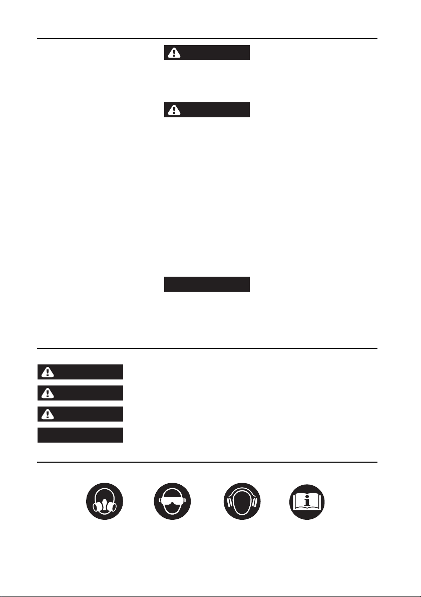
Safety Symbol Identification
Wear Respiratory
Protection
(Dwg. MHP2598)
2 04662995_ed4
Wear Eye
Protection
Wear Hearing
Protection
Read Manuals Before
Operating Product
Page 3
Placing Starter in Service
ST6 50 B P 03 R 31 045
HOW TO ORDER A STARTER
STARTER
ARC
HALF 50
FULL 99
GEAR
RATIO
P = PRE-ENGAGED
FLANGE
03 = SAE03
PINION
CODE
PINION ROTATION
R = RIGHT
L = LEFT
ORIENTATION
045
090
135
180
225
270
315
Pinion Data
Part
Number
ST600-13-31 12 12 6/8 2.000 50.80 20.0 R/L 2.250 57.15
ST600-13-51 15 15 6/8 2.500 63.50 20.0 R/L 2.750 69.85
ST600-13-83 12 12 3.5 Module 1.515 38.50 20.0 R/L 1.882 47.80
ST600-13-91 14 16 3.5 Module 1.929 49.00 20.0 R/L 2.441 62.00
ST600-13-942 14 15 3.5 Module 1.929 49.00 15.0 R/L 2.301 58.45
* Pinion Code must be specified when ordering.
Number
of Teeth
Blank DP/MOD
PD
inches mm inches mm
PA Ro tati on
OD
04662995_ed4 3
Page 4

Installation
NOTICE
For maximum performance, read this manual prior to
installation or operation of Series ST600 Starters.
General Information
1. This starter is designed for flange mounting at the inlet.
The Flange Mounting Kit is required for installation. All
Piping, hoses and valving must be clean prior to
installation. Make sure that the starter inlet is free of dirt
and foreign material during installation.
2. Engine design often requires mounting the starter
underneath in extremely close quarters, and even though
two of the mounting bolt holes are easy to reach, the third
one is less accessible. To install a starter, the following
tools are required: regular ratchet wrench, sockets,
universal joint, socket extension and single or double-end
box wrench.
3. Improper hook-up impairs the efficiency of a Starter.
Pressure Lines smaller than those recommended will
reduce the volume of air to the motor and the use of
reducers for piped-away applications in the exhaust port
will restrict the exhaust causing back pressure to the
motor resulting in reduced perfor mance. Keep the
number of tees and elbows, and the length of the supply
line upto a minimum. Use 1-1/2” hose or pipe for supply
lines up to 15 feet long: use 2” hose or pipe if the supply
line is over 15 feet long.
4. Install a 300 mesh strainer in the inlet line for each starter.
These 300 mesh strainers provide 50 micron filtration and
offer significant protection against supply line
contaminants which could damage the turbine
components. Ingersoll Rand offers 3 sizes:
ST900-267-24 for 1-1/2 inch lines, ST900-267-32 for 2
inch lines and ST900-267-64 for 4 inch lines.
Replacement elements are: ST900-266-24 for 1-1/2 inch,
ST900-266-32 for 2 inch and ST900-266-64 for 4 inch
lines.
5. Make your connections bubble tight to avoid unnecessary
costs and delays. On all threaded connections
throughout the system, use Ingersoll Rand No.SMB-441
Sealant, non-hardening No.2 Permatex or always run the
air supply line for the side or top of the receiver, never at
or near the bottom. Moisture in the air collects at the
bottom of the receiver resulting in damage which could
cause the valves to become inoperative. Periodically,
open the petcock at the bottom of the tank to drain the
water.
6. We recommend installation of a “glad hand” in vehicular
applications for emergency re-pressurizing of the system.
To keep the “glad hand” clean and free of dirt and to
protect it from damage, a second “glad hand” closed by a
pipe plug can be mated to it, or a “glad hand” protector
bracket can be used.
Orientation of the Starter
If the factory orientation will not fit your engine due to radial
location of the Drive Housing or location of the inlet and/or
exhaust ports, re-orient the starter as follows:
1. Refer to the dimension illustration and note that the drive
housing can be located in anyone of eight radial positions
relative to the air inlet (motor housing).
2. Study the engine mounting requirements, and determine
the required orientation of the Drive Housing relative to
the Gear Case. If the Drive Housing has to be reoriented,
remove the eight Drive Housing Cap Screws and rotate
the Drive Housing to its required positi on.
Mounting the Air Starter
1. Study the Piping diagram on Page 5.
2. The air receiver tank for a starter installation must meet
SAE J10B specifications. It must have a working
pressure capability equal to or grea ter than the maximum
pressure at which the starter will be operated.
3. When connecting the starter to a receiver tank that is
already in service, bleed off the air pressure by opening
the drain valve.
WARNING
Bleed off the air pressure through a valve or petcock. Do
not remove a plug from the tank while the tank is still
pressurized. Drain off any water that has accumulated in
the bottom of the tank.
4. Using a 1-1/2” short nipple, install the SRV150 Starter
Relay Valve on the end of the receiver tank as shown in
the piping diagram.
NOTICE
Make certain the connection is made to the inlet side of
the Relay valve indicated by the word “IN” cast on the
valve body.
5. Install the No.SMB-G618 Starter Control Valve on the
dash panel (for vehicular installations) or some other
appropriate panel (for stationary installations.)
6. Mount the No.150BMP-1064 Air Pressure Gauge on or
adjacent to the control panel. It should be located where it
is readily visible to the operator of the Control Valve.
7. Connect the Starter Control Valve to the Relay Valve with
1/4” hose. Install a Tee in this line with a short feeder
hose to the Pressure Gauge.
NOTICE
Make certain the hose is connected to the “SUPPLY”
side of the Starter Control Valve.
8. To determine the exact length of 1-1/2” air hose required,
run a piece of heavy-duty hose or some other flexible
tubing of the same diameter from the Relay Valve on the
receiver to the starter location on the engine.
9. Attach the 1-1/2” air hose to the outlet side of the Relay
Valve, and run the hose through the frame to its final
position at the starter location.
10. At this point, determine if it is feasible or practical to
attach the hose to the starter before or after the starter is
actually mounted. In many cases, it may be necessary to
attach the hose to the starter before mounting.
11. If possible, libe rally grease the teeth on t he ring gear with
a good, sticky gear grease or motorcycle chain lube. This
will help promote the life of the ring gear and the Starter
Pinion.
12. Place the starter into position, and mount it on the
flywheel bell housing. Tighten the mounting bolts to
100-ft-lb (136 Nm) of torque.
13. Pressurize the complete starting system and check every
connection with a soap bubble test. There must be no
leaks.
4 04662995_ed4
Page 5
Piping Diagram
PIPING DIAGRAM FOR A TYPICAL STATIONARY INSTALLATION: PRE-ENGAGED
SOLENOID VALVE - 120 VOLT
*150BMP-2450
(2) LEADS TO OPERATORS
STARTING SWITCH.
OPTIONAL CONTROL CIRCUIT UTILIZING
ELECTRIC SOLENOID CONTROL VALVE AND
PANEL MOUNTED SWITCH.
#4 HOSE (1/4)
STARTER CONTROL VALVE
* SMB-618 (BRASS / AIR)
INLET FLANGE KIT
*ST700-K166
(Dwg. TPE_1028_01)
AIR PRESSURE GAGE
* 150BMP-1064L
(AIR ONLY)
JIC 37° ADAPTOR 1/4 NPT
* SS350-MC4
#4 HOSE (1/4)
#4 HOSE (1/4)
1 1/2 HOSE
RELAY VALVE 1 1/2
*SRV150
JIC 37° ADAPTOR 1 1/2 NPT
INLET FLANGE KIT
*ST700-K166
EXHAUST
NOTE:
FOR ALL APPLICATIONS USE SEALANT * SMB-441 OR EQUIVALENT
ON ALL PIPE CONNECTIONS.
* INDICATES INGERSOLL RAND PART NUMBER
RELIEF VALVE SET AT 15 PSI
ABOVE REGULATOR SETTING.
STRAINER
* ST900-267-24
PRESSURE REGULATOR
(MAXIMUM SETTING NOT TO EXCEED
PRESSURE RATING SHOWN ON
STARTER NAMEPLATE)
PIPING DIAGRAM FOR A TYPICAL VEHICULAR INSTALLATION: PRE-ENGAGED
SOLENOID VALVE - 12 VOLT
STARTER CONTROL VALVE
*SMB-618 (BRASS/AIR)
#4 HOSE (1/4”)
1 1/2” HOSE
1 1/2” INLET SIZE
EXHAUST
# HOSE (1/4”)
JIC 37° ADAPTER
1 1/2” NPT
RELAY VALVE 1 1/4”
*SRV150
AIR PRESSURE GAGE
*150BMP-1064L
“OPTIONAL CONTROL CIRCUIT UTILIZING
ELECTRIC SOLENOID CONTROL VALVE AND
PANEL MOUNTED SWITCH.” (AIR ONLY)
1 1/2” PIPE ADAPTER
NOTE:
USE SEALANT ON ALL PIPE
CONNECTIONS. *SMB-441
* INDICATES INGERSOLL RAND PART NUMBER
*150BMP-1051B
JIC 37° ADAPTOR 1/4” NPT
*SS350-MC4
CHECK VALVE
*150BMP-1056
AIR RECEIVER TANK
(2) LEADS TO OPERATORS
STARTING SWITCH.
DRAIN VALVE 1/2” NPT
*150BMP-1067
HIGH PRESSURE
AIR SUPPLY.
AIR SUPPLY FROM
DRY AIR BRAKE TANK
04662995_ed4 5
Page 6

Mounting Dimensions
(0.50)
[(12.70)]
(0.50)
[(12.70)]
(1.75)
[(44.57)]
SECTION A-A
(2.00)
[(50.92)]
ø (3.62)
[(91.90)]
3X (120°)
ø (5.75)
[(146.05)]
PINION
PINION ROTATION
“R” = RIGHT
ARC
STARTER
ORIENTATION OPTIONS
“L” = LEFT
FLANGE
- AIR
STD 00
HALF 55
FULL 99
DUAL INCH
DIMENSIONS MM
8 @ 45°
DRIVE HOUSING
03 SAE 03
- STD
I INERTIA
P PRE-ENGAGED
RATIO
A
(.60)
[(15.24)]
ø (5.28)
[(134.24)]
NOTES:
1. Please read instructions before attempting to reorient.
2. Starter weight is 39 Lbs.
3. Not to be used with natural gas.
1/4” NPT
CONTROL PORT
OUTLET
(4.48)
[(113.74)]
(5.64)
[(143.31)]
1/4” NPT
CONTROL PORTINLET
ST600 PRE-ENGAGED MOUNTING DIMENSIONS
(12.023)
(1.41)
[(35.71)]
(2.75)
[(69.85)]
[(305.384)]
STANDARD INLET FLANGE KIT
ST700-K166
A
(INCLUDES MOUNTING HARDWARE
(4.23)
(3.49)
[(107.46)]
[(88.54)]
(4.96)
[(125.93)]
ø (6.25)
[(158.75)]
(Dwg. TPE_1027)
6 04662995_ed4
Page 7

ST600 Turbine Powered Starter - Section View
2
3
4
5
6
11
12
7
8
1
A
9
10
14
15
13
20
16
18
17
19
21
22
23
24
SECTION A-A
A
(Dwg.TPE_1029)
04662995_ed4 7
Page 8

ST600 Turbine Powered Starter - Exploded Diagram
(Dwg.TPE_1030)
8 04662995_ed4
Page 9

ST600 Turbine Powered Starter - Parts List
Item Description Part Number Item Description Part Number
1 Screw ST700-737 18 Spring ST600-700
2 Spring D10-275 19 Spring Seat SS350-191
3 Deflector ST700-735 20 Screw (8) Y99-52
4 Exhaust Cap ST600-562 21 Drive Housing Assembly ST600-K300
5 O-Ring ST700-67 22 Pinion Collar ST600-175
6 Motor Assembly 23 Drive Pinion
for LH rotation models ST650L-A53B for ST650BP03L31, ST699BP03L31,
for RH rotation models ST650R-A53B ST650BP03R31 and ST699BP03R31 ST600-13-31
7 Deflector ST600-111 for ST650BP03L51, ST699BP03L51,
8 O-Ring Y325-253 ST650BP03R51 and ST699BP03R51 ST600-13-51
9 Wave Spring ST600-244 for ST650BP03L83 and ST650BP03R83 ST600-13-83
10 Gear Package Assembly ST600C-APGR for ST650BP03L91, ST699BP03L91,
11 Flange Kit ST700-K166 ST650BP03R91 and ST699BP03R91 ST600-13-91
12 Motor Housing Assembly ST600-A40 for ST650BP03L942, ST699BP03L942,
13 O-Ring SS350-151 ST650BP03R942 and ST699BP03R942 ST600-13-942
14 O-Ring SS800-337 24 Screw
15 Piston ST600-703 for LH rotation models ST600L-394
16 Retaining Ring SS350-107 for RH rotation models ST600R-394
17 Drive Package Assembly
for LH rotation models ST600L-APDR
for RH rotation models ST600R-APDR
04662995_ed4 9
Page 10

Maintenance
WARNING
Always wear eye protection when operating or
performing any maintenance on this starter. Always turn
off the air supply and disconnect the air supply hose
before installing, removing or adjusting any accessory
on this starter or before performing any maintenance on
this starter.
Disassembly
General Information
1. Do not disassemble the Starter any further than
necessary to replace worn or damaged parts.
2. When grasping a part in a vise, always use leathercovered or copper-covered vise jaws to protect the
surface of the part and help prevent distortion. This is
particularly true of threaded members.
3. Do not remove any part which is a press fit in or on a
subassembly unless the removal of that part is necessary
for replacement or repairs.
4. Always have a complete set of seals and O-Rings on
hand before starting any overhaul of a Series ST600
Turbine Starter. Never reuse old seals or O-Rings.
5. Do not press any needle bearing from a part unless you
have a new needle bearing on hand for installation.
Needle bearings are always damaged during the removal
process.
Disassembly of the Starter
1. Place the Starter on a workbench with Exhaust end
down.
2. Remove the Drive Pinion Retainin g Screw (24).
NOTICE
Models ending in R31, R51, R83, R91 and R942 have a
left-hand thread. Models ending in L31, L51, L83, L91 and
L942 have a right-hand thread.
Assembly
General Instructions
1. Always press on the inner ring of a ball-type bearing
when installing the bearing on a shaft.
2. Always press on the outer ring of a ball-type bearing
when pressing the bearing into a bearing recess.
3. Whenever grasping a starter or part in a vise, always use
leather-covered or copper-covered vise jaws. Take extra
care with threaded parts or housings.
4. Except for bearings, always clean every part and wipe
every part with a thin film of oil or stated type of grease
before installation.
5. Check every bearing for ro ughness. If an open bearing
must be cleaned, wash it thoroughly in a suitable
cleaning solution and dry with a clean cloth. Sealed or
shielded bearings should neve r be cleaned. Work grease
thoroughly into every open bea ring before installation.
6. Apply a film of O-ring lubricant to all O-rings before final
Assembly.
7. Unless otherwise noted, alw ays press on the stamped
end of a needle bearing when installing the needle
bearing in a recess. Use a bearing inserting tool similar to
the one shown in Dwg.TPD786.
Lubrication
Each time a Series ST600 Starter is disassembled for
maintenance or repair, lubricate the starter as follows:
1. Lubricate the inside diameter of the Drive Shaft (17) with
Ingersoll Rand No.130 Grease.
2. Lubricate the Pinion end of the Drive Shaft with
Ingersoll Rand No.11 Grease.
3. Wipe a thin film of Ingersoll Rand No.130 Grease in the
bore of the Drive Housing (12).
4. Roll the Piston Return Spring (18) in Ingersoll Rand
No.130 Grease.
5. Coat the outside of the Piston (15) with Ingersoll Rand
No.130 Grease.
6. Lubricate all O-Rings with O-Ring lubricant.
3. Remove the Drive Pinion (23) with Pinion Collar attached
off the Drive Shaft.
4. Unscrew and remove the eight Drive Housing Cap
Screws (20).
5. Remove Drive Housing (21).
6. Remove Spring (18) and seat (19).
7. Slide the Drive Package Assembly (17) from the Drive
Housing.
8. Place Motor Housing (12) in a copper faced vise
clamping on the flats of the Exhaust Cap (4).
9. Insert a rod in the inlet and turn counterclockwise to
remove exhaust cover (4).
NOTICE
Transmission Fluid will drain and build-up on the
Exhaust Cover. Handle Exhaust Cover with care.
10. Remove Motor Housing from vise and place on
workbench with Exhaust end upward.
11. Grasp the rear of the Motor Assembly (6) and pull it from
the rear of the Motor Housing.
12. Place Motor Housing in drip pan with Exhaust end down
to allow transmission fluid to drain.
13. Press on clutch Shaft through the front end to release
Gear Package (10) and Front Deflector (7).
SHOULDER TO
REGULATE DEPTH
(Dwg.TPD786)
NEEDLE BEARING INSERTING TOOL
15°
PILOT TO FIT I.D. OF BEARING.
LENGTH OF PILOT TO BE
APPROXIMATELY 1/8” LESS THAN
LENGTH OF BEARING
10 04662995_ed4
Page 11

Assembly of the Starter
1. Place Motor Housing on a workbench, exhaust end up.
2. Grasp Gear Package Assembly (10) and insert into Motor
Housing. Rotate Gear Package to align Planet Gear
Teeth with Ring Gear Teeth.
3. Place Wave Spring (9) onto Front Deflector (7).
4. Insert Front Deflector (7) into Motor Housing applying
force until it seats against Ring Gear.
5. Add 275 ml of Dextron®** II Automatic Transmission fluid
through the hole in the Front Deflector.
6. Before installing the Motor Assembly, coat the O-Rings
on the Motor Assembly and the inside of the Cylinder wit h
O-Ring lubricant. Install the Motor Assembly through the
rear of the Motor Housing with geared end of the rotor
toward the front.
NOTICE
Be careful not to damage O-Rings during assembly. If
necessary a .010” thick sleeve may be inserted to cover
inlet hole. Remove once Motor Assembly has been
installed.
7. Coat the Exhaust O-Ring (5) with O-Ring lubricant and
install in the groove on the Exhaust Cap (4).
8. Align the Exhaust Cap in the rear of the Motor Housing
and rotate until it seats. Tighten the Exhaust Cap to a
final torque of 50 ft.-lb.
9. Install the Deflector (3), Spring (2) and Screw (1) in the
rear of the Housing Exhaust Cover.
NOTICE
Coat the threads of the Deflector Retaining Screw with
Ingersoll Rand SMB-441 Sealant.
10. Place Starter in vise with exhaust end down clamping on
flats of Exhaust Cap.
11. Grasp Drive Package Assembly and align the spline teeth
of Drive Package Assembly with spline teeth of the Gear
Package Assembly. Apply pressure until Piston is seated.
12. Install Spring (18) and Seat (19).
13. Carefully position the Drive Housing (12) onto the Motor
Housing.
14. Install the Drive Housing Cap Screws (20) and torque to
20-25 ft-lbs.
15. Refer to TPE_1027 for prope r orientation.
16. Install Pinion (23) with Collar (22) attached. Align the
notches of the Pinion with notche s in the Drive Shaft.
17. Install the Drive Pinion Retaining Screw (24) into the end
of the Drive Shaft and torque to 18 0-220 ft-lb.
NOTICE
Models ending in R31, R51, R83, R91 and R942 have a
left-hand thread. Models ending in L31, L51, L83, L91 and
L942 have a right-hand thread.
NOTICE
After assembling the exhaust cover to the starter, add
20 ml of Dextron® **II Automatic Transmission Fluid
through the screw hole in the Exhaust Cover.
** Registered Trademark of Exxon Corp.
Troubleshooting Guide
Trouble Probable Cause Solution
Motor will not run No air supply Check for blockage or damage to air supply lines or tank.
Damaged motor assembly Inspect Motor Assembly and power train and repair or
Foreign material in motor and/or piping Remove Motor Assembly and/or piping and remove
Blocked exhaust system Remove Housing Exhaust Cover (1) and check for
Defective Control Valve or Relay Valve Replace Control Valve or Relay Valve.
Low air pressure to Starter Check air supply.
Restricted air supply line. Check for blockage or damage to air lines.
Relay Valve malfunctioning Clean or replace lines or Relay Valve. Lube relay Valve.
Loss of Power Exhaust flow restricted Check for blocked or damaged piping. Clean or replace
Worn motor parts Remove the motor from the Motor Housing (17) and
Lack of air to starter Check for clogged or damaged air line between relay valve
replace if necessary.
blockage.
blockage.
piping. Check for dirt or foreign material and clean or
remove. Check for ice build-up. Melt ice and reduce
moisture build-up to Starter.
disassemble the motor. Examine all parts and replace any
that are worn or damaged.
and starter. Check relay valve to determine if it is
functioning properly. Check air tank.
04662995_ed4 11
Page 12

Parts and Maintenance
NOTICE
The use of other than genuine Ingersoll Rand replacement parts may result in safety hazards, decreased motor
performance, and increased maintenance, and may invalidate all warranties.
Ingersoll Rand is not responsible for customer modification of motors for applications on which Ingersoll Rand was not
consulted.
Repairs should be made only by authorized trained personnel. Consult your nearest Ingersoll Rand Authorized Service
center.
When the life of the motor has expired, it is recommended that the motor be disassembled, degreased and parts be separated by
material so that they can be recycled.
Manuals can be downloaded from www.irtools.com.
Refer all communications to the nearest Ingers oll Rand Office or Distributor.
12 04662995_ed4
Page 13

Notes
Page 14

Notes
Page 15

Notes
Page 16

www.irtools.com
© 2006 Ingersoll Rand Company
 Loading...