

Page 1
Form P7648
Edition 1
August 2004
CCN 04579728
Operation and Maintenance Manual
for
Series SRV125F
Starter Relay Valve
NOTICE
Series SRV125F Starter Relay valves are designed for controlling fluid flow in conjunction with Air Starting
Systems
.
WARNING
• IMPORTANT SAFETY INFORMATION ENCLOSED - SAVE THESE INSTRUCTIONS.
•
Read and understand this manual before operating Valve.
• Failure to observe the following warnings could result in injury.
PLACING THE VALVE IN SERVICE
• Always install, operate, inspect and maintain this product in accordance with all applicable standards and regulations (local, state, country, federal, etc.).
• Always use clean, dry air at a pressure which does not
exceed the pressure rating listed on the valve.
• Do not use damaged, frayed or deteriorated air hoses &
fittings.
• Always turn off the air and disconnect the air hose
before installing, removing or adjusting any accessory
on this valve, or before performing any maintenance on
this valve or accessory.
• Do not lubricate the valve with flammable or volatile
liquids such as kerosene, diesel or jet fuel, use only
recommended lubricants.
• Series SRV125F Valves are not designed for working
in explosive atmospheres.
• Do not remove any labels, replace any damaged labels.
• Operate this valve only when properly installed in the
Air Starting System.
• Always bleed off the air pressure before attempting to
remove the Starter Relay Valve from the Receiver or
before attempting to perform any maintenance on the
Starter Relay Valve.
• Never attempt to remove the Retaining Ring (12) from
the bottom side of the Starter Relay Valve until the air
pressure has bled off. If the Retaining Ring is removed
while there is pressure in the Receiver, internal parts of
the Starter Relay Valve will be blown out with considerable force.
• Use only recommended Ingersoll-Rand accessories.
Refer All Communications to the Nearest
Ingersoll-Rand Office or Distributor.
© Ingersoll-Rand Company 2004
P7630 Edition 1
Printed in U.S.A
1
Page 2
USING THE VALVE
• This product is not designed for working in explosive
environments, including those caused by fumes & dust,
or near flammable materials.
• This product is not insulated against electric shock.
• Never use a damaged or malfunctioning product or
• Do not use this product for purposes other than those
recommended.
• Operate this product only when properly installed in
the Air Starting System.
• Use only recommended Ingersoll-Rand accessories.
accessory.
• Do not modify this product, safety devices, or accessories.
NOTICE
• The use of other than genuine Ingersoll-Rand replacement parts may result in safety hazards, decreased starter performance, and increased maintenance, and may invalidate all warranties.
• Repairs should be made only by authorized trained personnel. Consult your nearest Ingersoll-Rand Authorized Service
Center.
• Ingersoll-Rand is not responsible for customer modification of starters for applications on which Ingersoll-Rand was not
consulted.
• It is the responsibility of the employer to place the information on this manual in to the hands of the operator.
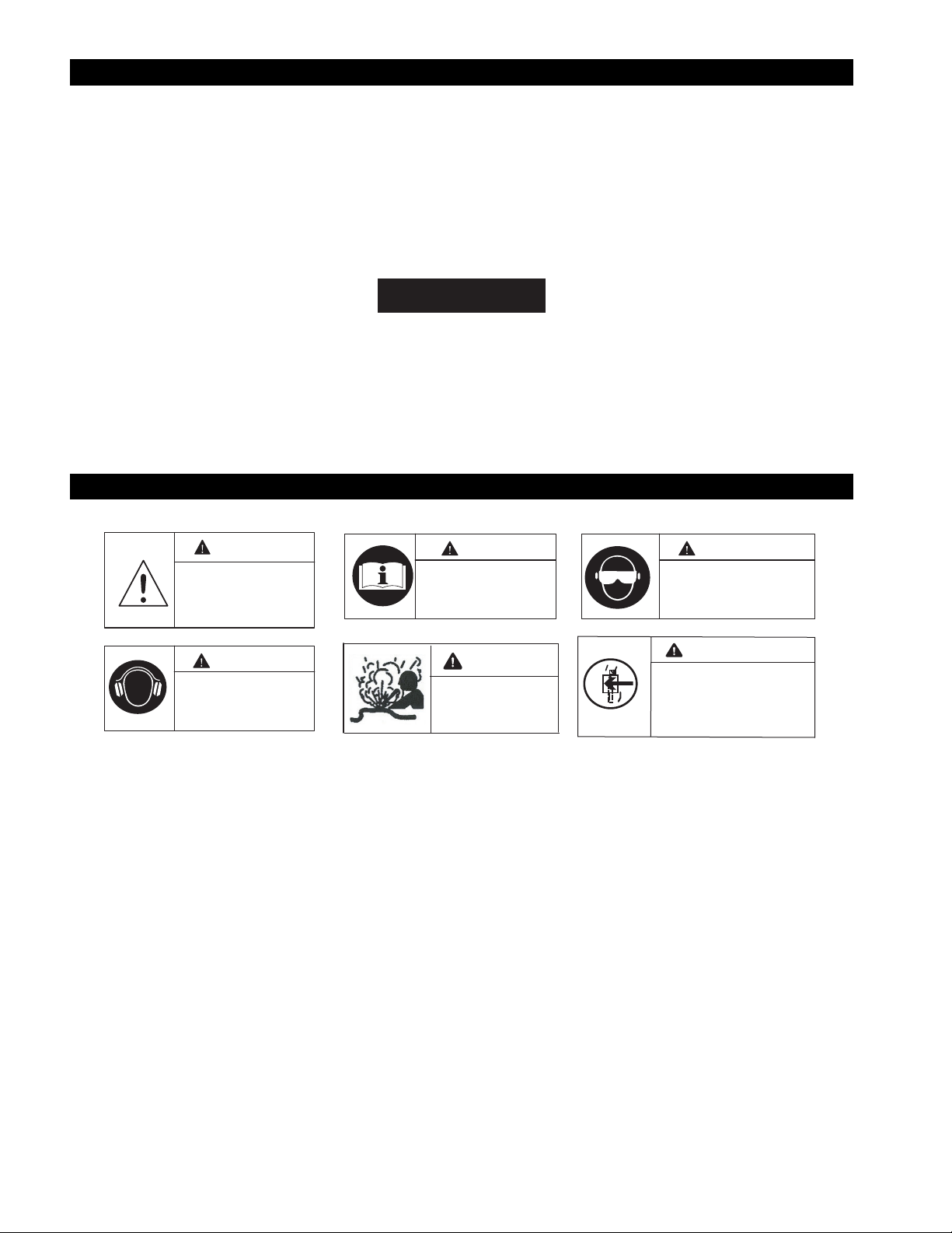
WARNING SYMBOL IDENTIFICATION
WARNING
This is the safety alert symbol.
It is used to alert you to potential
personal injury hazards. Obey all
safety messages that follow this
symbol to avoid possible injury
or death.
NGWARNI
Read this manual before
operating Starter.
Always wear eye protection when
operating or performing
maintenance on this Starter.
NGWARNI
WARNING
Always wear hearing
protection when operating
this Starter.
NGWARNI
Do not use damaged, frayed or
deteriorated air hoses & fittings
NGWARNI
Always turn off the air supply, bleed
OFF
the air pressure & disconnect the air
supply hose before installing,
removing or adjusting any
accessory on this product or before
performing any maintenance on this
product or any accessory.
2
P7648 Edition 1
Page 3
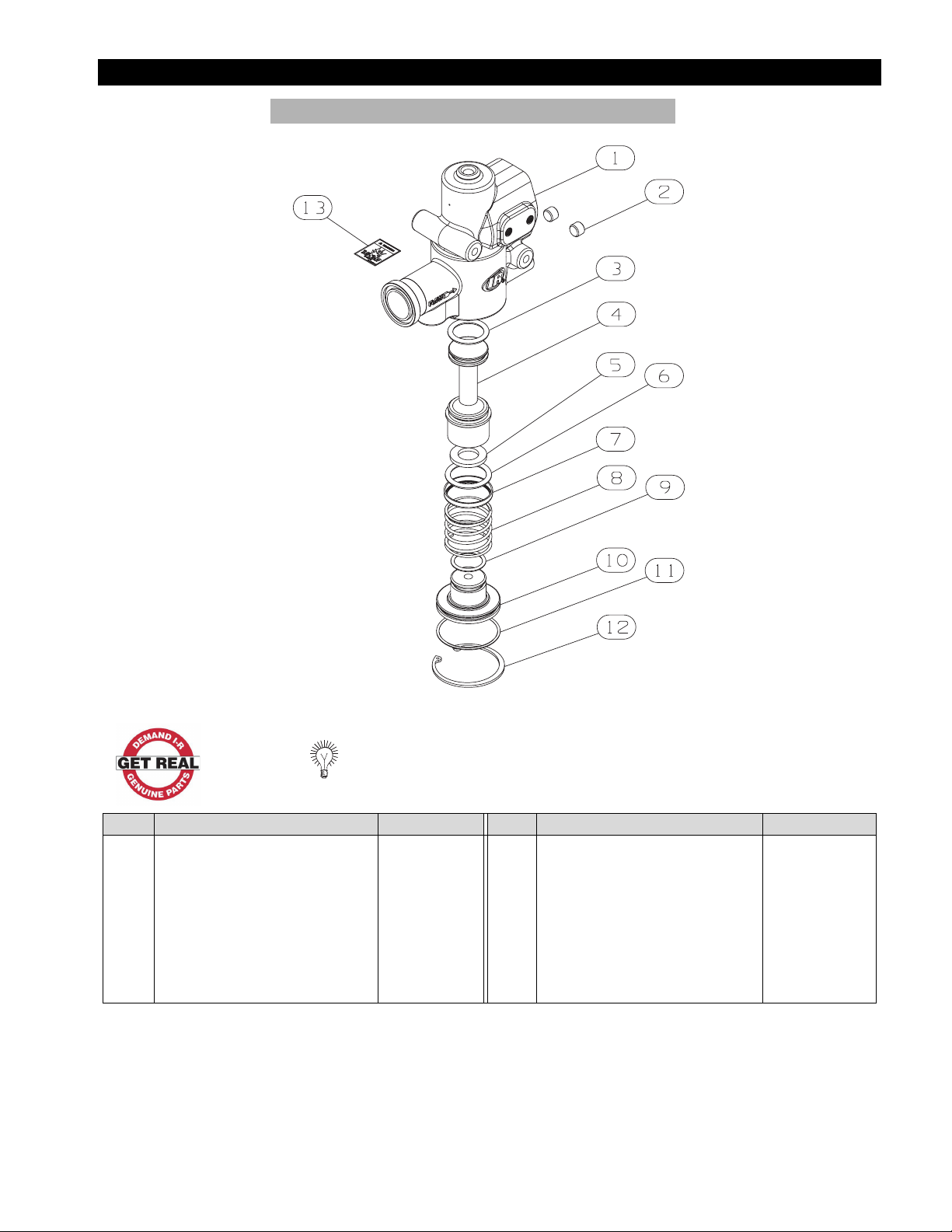
EXPLODED VIEW AND PARTS LIST
SERIES SRV125F STARTER RELAY VALVE
(Dwg. TP2184)
When ordering, use applicable part number
Item Part Description Part Number Item Part Description Part Number
1 Valve Housing . . . . . . . . . . . . . . . . . . . . SRV125F-40 10 End Plug . . . . . . . . . . . . . . . . . . . . . . . . . SRV150-338
2 Pipe Plug (2 required) . . . . . . . . . . . . . . HSPPS-2 11 End Plug Seal O-ring . . . . . . . . . . . . . . . Y327-143 *
3 Upper Piston O-Ring . . . . . . . . . . . . . . . SRV150-210 * 12 Retaining Ring . . . . . . . . . . . . . . . . . . . . SRV150-340 *
4 Piston . . . . . . . . . . . . . . . . . . . . . . . . . . . SRV150-246 13 Warning Label . . . . . . . . . . . . . . . . . . . . . 04333274
5 Bumper . . . . . . . . . . . . . . . . . . . . . . . . . . SRV150-339 *
6 Piston O-ring . . . . . . . . . . . . . . . . . . . . . SRV150-211 * + Tune Up Kit. . . . . . . . . . . . . . . . . . . . . . . SRV150-TK3
7 O-ring Retainer. . . . . . . . . . . . . . . . . . . . SRV150-33 * + Pipe Sealant. . . . . . . . . . . . . . . . . . . . . . . SMB-441
8 Spring . . . . . . . . . . . . . . . . . . . . . . . . . . . SRV150-250 + Grease . . . . . . . . . . . . . . . . . . . . . . . . . . . SRV-GR55 *
9 End Plug O-ring . . . . . . . . . . . . . . . . . . . SRV150-67 *
* Indicates parts available in Tune Up Kit
Items Not Shown
+
P7648 Edition 1
3
Page 4

OPTIONAL EQUIPMENT
(Dwg. TP2212)
When ordering, use applicable part number
Item Part Description Part Number Item Part Description Part Number
Solenoid and Mounting Hardware - Position 1 Pilot Port Hardware - Position 2
A Solenoid L 90° Elbow with Push to Lock . . . . . . . . . EL90-4M4DOT
12 Volt, Pioneer Connections . . . . . . . . 150BMP-A1051C M 90° Elbow with JIC 37° . . . . . . . . . . . . . EL90-4M437M
12 Volt, Wire Leads . . . . . . . . . . . . . . . 150BMP-1051B Left and Right Live Air Port hardware - Position 3 and 4
12 Volt, Wire Leads . . . . . . . . . . . . . . . 150BMP-2451B N 90° Elbow with Push to Lock . . . . . . . . . EL90-4M4DOT
B 90° Elbow with Push to Lock . . . . . . . . . . . EL90-4M4DOT O T Connection with Push to Lock . . . . . . 150TMP-MRT4M4
C Solenoid Mounting Bracket . . . . . . . . . . . . . 150TMP-2451 P Schrader Valve . . . . . . . . . . . . . . . . . . . . 04333654
D Solenoid Mounting Screw (2) . . . . . . . . . . . Y133-105C Q 1/4” Pipe Plug . . . . . . . . . . . . . . . . . . . . . HSPPS-2
E Solenoid Mounting Screw Washer (2). . . . . Y117-110 R T Fitting with 1/4” NPT . . . . . . . . . . . . . SRV125F-188
F Solenoid Mounting Bracket Screw (2) . . . . 150TMP-128 + Pressure Gauge . . . . . . . . . . . . . . . . . . . . SRV125F-1064
G Solenoid Mounting Bracket Washer (2) . . . Y14-516C Secondary Inlet Port Hardware - Position 5
H 90° Elbow with Push to Lock . . . . . . . . . . . EL90-4M4DOT S Check Valve . . . . . . . . . . . . . . . . . . . . . . ST400-1056
I Connection Hose . . . . . . . . . . . . . . . . . . . . . 150TMP-125 T Plug . . . . . . . . . . . . . . . . . . . . . . . . . . . . . SRV125F-34
J 90° Elbow with Push to Lock . . . . . . . . . . . EL90-4M4DOT U 1-1/4” Flange Kit . . . . . . . . . . . . . . . . . . ST500-K166
K Connection Hose . . . . . . . . . . . . . . . . . . . . . 150TMP-125
(+) Items Not Shown
For Position Coding information refer to Drawing 10554749
4
P7648 Edition 1
Page 5

PLACING THE STARTER RELAY VALVE IN SERVICE
WARNING
Always wear eye protection when performing any maintenance on this valve.
Pre-Installation
1. Clean the air line, o-ring groove and sealing surfaces to be
sure they are free of foreign material.
2. Ensure that enough space is left for removal and service of
this valve.
3. Ensure that the air line is suitably aligned and supported to
avoid strained joints.
4. Do not over tighten the air line connections.
5. All Starter Relay Valves are to be installed with the Valve in
the vertical position.
NOTICE
This Starter Relay Valve is specially designed and
manufactured by Ingersoll-Rand for use on Starter
Installations. Install it in accordance with the following
instructions.
Installation
1. Place the O-Ring supplied with the flange fitting into the
groove on the Starter Relay Valve.
2. Mount the Starter Relay Valve to the tank using ST500-K166
Flange Assembly. The air flow arrow must point toward the
starter.
3. Check the O-Ring to see that it properly seated in the groove
to prevent cutting.
4. Push the two clamp halves inward as far as they will go.
5. Tighten the four flange bolts in an alternating pattern to
35-45 ft-lbs (47-61Nm) torque.
6. Attach the air hose from the outlet side of a 3-way normally
vented Control Valve to the small tapped hole in the top of
the Starter Relay Valve. Use SMB-441 Ingersoll-Rand Sealant on the male thread.
P7648 Edition 1
5
Page 6

MAINTENANCE
WARNING
Always wear eye protection when lubricating or performing
maintenance on the Starter Relay Valve. Always bleed off the
air pressure before lubricating or performing any maintenance on the Starter Relay Valve.
Lubrication
Periodically lubricate the Starter Relay Valve as follows:
1. Bleed off the air pressure.
2. Disconnect the No. 4 Hose from the tank at the control air
supply port near the bottom of the Starter Relay Valve opposite the air inlet. In some installations, this ¼" N.P.T. will be
plugged.
3. Remove the plug. Squirt approximately 1 ounce (30 cc) of
10W oil into the Starter Relay Valve through the hose plug
opening.
4. Reconnect the hose or reinstall the plug.
Installation of the Tune Up Kit
Disassembly of the Starter Relay Valve
1. Bleed off the air pressure.
2. Clamp the Starter Relay Valve in a vise with the Retaining
Ring (12) facing up.
3. Carefully remove the Retaining Ring. The End Plug (10)
should spring out. If it does not, tap the Valve Housing (1)
lightly with a soft hammer until the End Plug springs out.
4. Remove the End Plug, Spring (8), and Piston Assembly (4).
5. Remove and discard all of the used O-Rings and the Bumper
(5).
6. Clean all other parts in a clean, suitable cleaning solution in a
well ventilated area.
Assembly of the Starter Relay Valve
1. Using O-Ring lubricant, lubricate and install the new Piston
O-Ring (6) and the new Upper Piston O-Ring (3) on the Piston (4).
NOTICE
NOTICE
No. SRV150-TK3 Tune Up Kit is available for maintaining the
Starter Relay Valve. This Tune Up Kit includes all O-Rings
(3,6,9,11), Bumper (5), O-Ring Retainer (7), End Plug
Retaining Ring (12) and Grease.
The Upper Piston O-Ring (3) is slightly larger in diameter
than the End Plug O-Ring (9).
2. Turn the Piston over and install the new Bumper (5).
3. Using O-Ring lubricant, lubricate and install the new End
Plug Seal O-Ring (11) and the new End Plug O-Ring (9) on
the End Plug (10).
4. Lubricate the lower small bore of the Valve Housing (1) with
O-ring lubricant.
5. Insert the Piston Assembly into the Valve Housing until the
Piston O-Ring (6) seats against the beveled face.
6. Install the O-Ring Retainer (7) with the large opening over
the Piston O-Ring.
7. Place the Piston Spring (8) on the Piston.
8. Place the End Plug Assembly on the Piston Spring.
9. Using a press to hold down the End Plug Assembly, install
the End Plug Retaining Ring (12).
6
P7648 Edition 1
Page 7

NOTES
P7648 Edition 1 7
Page 8

SERVICE CENTERS
Web: www.irtools.com/techdocuments
United States
IR ESS Customer Service /Distribution
Center
P.O. Box 618
510 Hester Drive
White House, TN 37188
United States
Phone: (888) START-AIR
Fax: (615) 672-0801
Canada
Marketing/Sales/Service Headquarters
Ingersoll-Rand Canada Inc.
51 Worcestor Road
Toronto, Ontario M9W 4K2
Phone: (416) 213-4500
Fax: (416) 213-4510
Europe/ Middle East/ Africa
Ingersoll-Rand Tool & Hoist Division
Zone du Chene Sorcier
BP 62
78346 Les Clayes sous Bois Cedex
France
Phone: +33-0130 07 6939
Fax: +33-0130 076980
Ingersoll-Rand Distribution Centre
Swan Lane
Hindley Green
Wigan
Lancashire WN2 4EZ
England
Phone: +44 (0) 1942 257131
Fax: +44 (0) 1942 526255
Latin America
Ingersoll-Rand – Latin America
Division
730 Northwest 107 Avenue
Street 300
Miami, FL 33172
Phone: (305) 559-0500
Fax: (305) 222-0864
Brasil
Ingersoll-Rand do Brasil Ltda.
Tool & Hoist Division
Av. Dr. Cardoso de Meio 1855
cj. 152-04548-005 Sao Paulo,. SP
Brasil
Phone: (55) 11 3049-8900
Fax: (55) 113846-4985
Chile
Ingersoll-Rand Chile
Nueva Tajamar 555, 15th fl.
Las Condes, Santiago
Chile
Phone: (56) 2 339-7939
Fax: (56) 2 339-7940
Mexico
INGERSOLL-RAND, S.A. de C.V.
Blvd. Centro Industrial # 11.
Col. Industrial Puente de Vigas. 54070
Tlanepantla, Edo. de Mexico
Mexico
Phone: (52) 8 503-6627
Fax: (52) 5 565-3072
Venezuela
Ingersoll-Rand Company
Centro Professional Eurobuilding
Piso 6 – Oficina 6-B
Chuao, Caracas
Phone: (58) 2 924-737
Fax: (58) 2 993-9276
Asia/Pacific
Australia
Ingersoll-Rand Australia. Ltd
1 Hartnett Drive
PMB 2, Carrum Downs BC, Vic.,
3201
Seaford, Victoria 3198
Australia
Phone: (61) 3 9554 1600
Fax: (61) 3 9554 1611
India
Ingersoll Rand Wadco Tools Ltd.
37-A, Site 4
Sahibabad Industrial Area
Ghaziabad 201 010 (U.P.)
India
Phone: (0120) 477-1001/2/3/4
Fax: (0120) 477-1005
Japan
Ingersoll-Rand Japan,Ltd.
LS Bldg. 2F
1-1-17 Kami-Ohsaki
Shinagawa-ku, Tokyo
141-0020
Japan
Phone: (81) 3-5420-3392
Fax: (81) 3-5420-9116
Korea
Ingersoll-Rand T&H
#395-43, Seogyo-Dong, Mapo-Ku
Seoul, Korea 121-210
Phone: (82) 2 330 8090/1
Fax: (82) 2 31415893
8 P7648 Edition 1
 Loading...