

Page 1

Form MHD56028
PARTS, OPERATION AND MAINTENANCE MANUAL
for
MANUAL CHAIN HOIST MODELS
MCH5-005 MCH5-010 MCH5-015
1/2 ton 1 ton 1-1/2 ton
MCH5-020 MCH5-030 MCH5-050
2 ton 3 ton 5 ton
Unless otherwise noted, tons in this manual are metric tons (2,200 lbs.)
READ THIS MANUAL BEFORE USING THESE PRODUCTS. This manual
contains important safety, installation, operation and maintenance
information. Make this manual available to all persons responsible for the
operation, installation and maintenance of these products.
WARNING
Do not use this hoist for lifting, supporting, or transporting people or lifting or supporting
loads over people.
Always operate, inspect and maintain this hoist in accordance with American National
Standards Institute Safety Code (ASME B30.16) and any other applicable safety codes and
regulations.
Refer all communications to the nearest Ingersoll-Rand Material Handling Office or
Distributor.
Form MHD56028
Edition 7
October 1996
71049530
©
1996 Ingersoll-Rand Company
Page 2

SAFETY INFORMATION
This manual provides important information for all personnel
involved with the safe installation, operation and proper
maintenance of this product. Even if you feel you are familiar
with this or similar equipment, you should read this manual
before operating the product.
Danger, Warning, Caution and Notice
Throughout this manual there are steps and procedures which, if
not followed, may result in a injury. The following signal words
are used to identify the level of potential hazard.
DANGER
WARNING
CAUTION
NOTICE
Danger is used to indicate the presence
of a hazard which will cause severe
injury, death, or substantial property
damage if the warning is ignored.
Warning is used to indicate the
presence of a hazard which can cause
severe injury, death, or substantial
property damage if the warning is
ignored.
Caution is used to indicate the presence
of a hazard which will or can cause
minor injury or property damage if the
warning is ignored.
Notice is used to notify people of
installation, operation, or maintenance
information which is important but not
hazard-related.
Safety Summary
WARNING
The National Safety Council, Accident Prevention Manual for
Industrial Operations, Eighth Edition and other recognized
safety sources make a common point: Employees who work
near cranes or assist in hooking on or arranging a load should be
instructed to keep out from under the load. From a safety
standpoint, one factor is paramount: conduct all lifting
operations in such a manner that if there were an equipment
failure, no personnel would be injured. This means keep out
from under a raised load and keep out of the line of force of any
load.
Ingersoll-Rand Material Handling hoists are manufactured in
accordance with the latest ASME B30.16 standards.
The Occupational Safety and Health Act of 1970, generally
places the burden of compliance with the user, not the
manufacturer. Many OSHA requirements are not concerned or
connected with the manufactured product but are, rather,
connected with the final installation. It is the owner’s and user’s
responsibility to determine the suitability of a product for any
particular use. It is recommended that all applicable industry,
trade association, federal, state and local regulations be checked.
Read all operating instructions and warnings before operation.
Rigging: It is the responsibility of the operator to exercise
caution, use common sense and be familiar with proper rigging
techniques. Refer to ASME B30.9 for rigging information,
American National Standards Institute, 1430 Broadway, New
York, NY 10018.
NOTICE
• Using other than genuine Ingersoll-Rand Material
Handling parts will void the warranty.
• Do not use this hoist for lifting, supporting, or transporting
people or lifting or supporting loads over people.
• Hoists are designed to provide a 4 to 1 safety factor. The
supporting structures and load-attaching devices used in
conjunction with this hoist must provide adequate support
to handle all hoist operations plus the weight of the hoist
and attached equipment. This is the customer’s
responsibility. If in doubt, consult a registered structural
engineer.
SAFE OPERATING INSTRUCTIONS
The following warnings and operating instructions have been
adapted in part from American National (Safety) Standard
ASME B30.16 (Overhead Hoists) and are intended to avoid
unsafe operating practices which might lead to injury or
property damage.
Ingersoll-Rand recognizes that most companies who use hoists
have a safety program in force in their plants. In the event you
are aware that some conflict exists between a rule set forth in
this publication and a similar rule already set by an individual
company, the more stringent of the two should take precedence.
Safe Operating Instructions are provided to make an operator
aware of dangerous practices to avoid and are not necessarily
limited to the following list. Refer to specific sections in the
manual for additional safety information.
1. Only allow personnel, trained in safety and operation of
this product, to operate the hoist.
2. Only operate a hoist if you are physically fit to do so.
3. When a “DO NOT OPERATE” sign is placed on the
hoist, do not operate the hoist until the sign has been
removed by designated personnel.
4. Before each shift, the operator should inspect the hoist for
wear or damage.
5. Never use a hoist which inspection indicates is worn or
damaged.
2
Page 3

6. Periodically, inspect the hoist thoroughly and replace worn
or damaged parts.
7. Lubricate the hoist regularly.
8. Do not use hoist if hook latch has been sprung or broken.
9. Check that the hook latches are engaged before using.
10. Never splice a hoist chain by inserting a bolt between links.
11. Only lift loads less than or equal to the rated capacity of the
hoist. Refer to “SPECIFICATION” section.
12. When using two hoists to suspend one load, select two
hoists each having a rated capacity equal to or more than
the load. This provides adequate safety in the event of a
sudden load shift.
13. Never place your hand inside the throat area of a hook.
14. Never use the hoist load chain as a sling.
15. Never operate a hoist when the load is not centered under
the hook. Do not “side pull” or “yard.”
16. Never operate a hoist with twisted, kinked, “capsized” or
damaged load chain.
17. Do not force a chain or hook into place by hammering.
18. Never insert the point of the hook into a chain link.
19. Be certain the load is properly seated in the saddle of the
hook and the hook latch is engaged.
SPECIFICATIONS
Model Code Explanation
Model Code Example MCH5 - 050 - 10 - 8
20. Do not support the load on the tip of the hook.
21. Never run the load chain over a sharp edge. Use a sheave.
22. Pay attention to the load at all times when operating the
hoist.
23. Always ensure that you, and all other people, are clear of
the path of the load. Do not lift a load over people.
24. Never use the hoist for lifting or lowering people, and
never allow anyone to stand on a suspended load.
25. Ease the slack out of the chain and sling when starting a
lift. Do not jerk the load.
26. Do not swing a suspended load.
27. Do not leave a load suspended when the hoist is unattended
or not in use.
28. Never weld or cut on a load suspended by the hoist.
29. Never use the hoist chain as a welding electrode.
30. Do not operate hoist if chain jumping, excessive noise,
jamming, overloading, or binding occurs.
31. Only operate the hoist with manual power.
32. After use, or when in a non-operational mode, the hoist
should be secured against unauthorized and unwarranted
use.
Series: MCH5
Hoist Capacity:
005 = 1/2 metric ton (1,100 lbs.)
010 = 1 metric ton (2,200 lbs.)
015 = 1-1/2 metric ton (3,300 lbs.)
020 = 2 metric ton (4,400 lbs.)
030 = 3 metric ton (6,600 lbs.)
050 = 5 metric ton (11,000 lbs.)
Lift (Hoist load chain/hook travel):
10 = 10 feet (3 m) (standard)
15 = 15 feet (5 m)
20 = 20 feet. (6 m)
XX = Specify length
F = Hoist without load chain
Hand Chain (Hand chain is 2 ft. less than lift):
8 = 8 ft. (10 foot lift minus 2 feet - standard)
13 = 10 ft. (15 foot lift minus 2 feet)
18 = 18 ft. (20 foot lift minus 2 feet)
XX = Specify length
3
Page 4
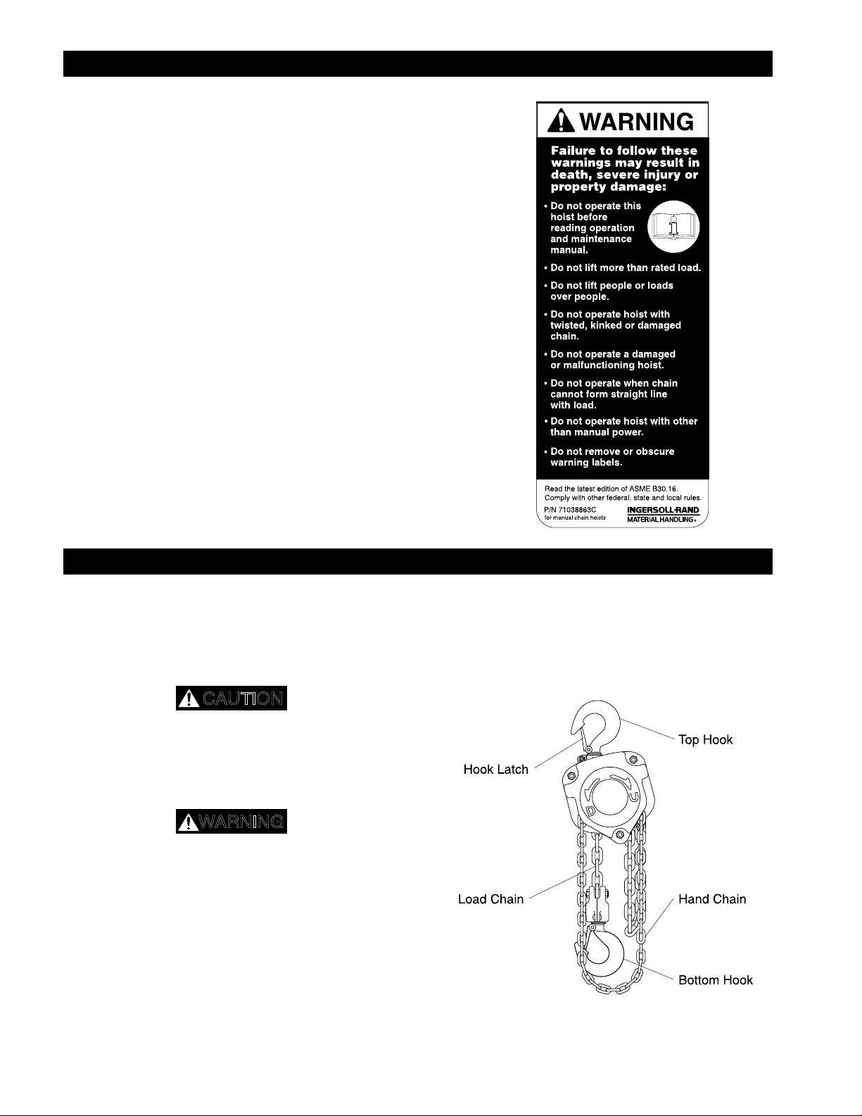
WARNING TAG
Each hoist is supplied from the factory with the safety tag
shown. If the tag is not attached to your unit, order a new tag
and install it. Refer to the parts list for the part number. Read
and obey all warnings and other safety information attached to
this hoist. Tag may be shown smaller than actual size.
INSTALLATION
Prior to installing the hoist, carefully inspect it for possible
shipping damage.
Hoists are supplied fully lubricated from the factory.
Lubrication of the load chain is recommended before initial
hoist operation.
CAUTION
• Owners and users are advised to examine specific, local or
other regulations, including American National Standards
Institute and/or OSHA Regulations which may apply to a
particular type of use of this product before installing or
putting hoist to use.
WARNING
• A falling load can cause injury or death. Before installing,
read “SAFETY INFORMATION”.
• Depending on the model selected, the hoist may weigh
more than 90 lbs. (41 kg). If parts of the hoist are dropped,
they can cause injury, death or property damage.
Adequately support the hoist during installation.
Hoists are designed to provide a 4 to 1 safety factor. The
supporting structures and load-attaching devices used in
conjunction with this hoist must provide adequate support to
handle all hoist operations plus the weight of the hoist and
attached equipment. This is the customer’s responsibility. If in
doubt, consult a registered structural engineer.
The MCH5 manual chain hoist must be used in a vertical
position to provide a straight line pull from top hook to bottom
hook. The hoist must be positioned so that it does not contact
the support members when in use. When operating in limited
areas suitable lifting attachments or slings must be used to
prevent the hoist body and hand chain from being obstructed.
(Dwg. MHP0442)
4
Page 5

Initial Operating Checks
Operate the hoist with a test load (10% of rated capacity) by
raising and lowering this load several times. Verify the brake
operation by lowering the same load to check load does not slip
when lowering stops.
NOTICE
• Each time a load is lifted, the operation of the brake should
be checked by raising the load slightly and stopping to
ensure the brake will hold the load before proceeding to lift
the load.
OPERATION
Familiarize operators and people responsible for hoist
installation and service with ASME B30.16 specifications prior
to placing the unit into service. All the requirements of this
specification, including testing should be met before approving
the hoist for operation.
The four most important aspects of hoist operation are:
1. Follow all safety instructions when operating the hoist.
2. Allow only people trained in safety and operation of this
hoist to operate the hoist.
3. Subject each hoist to a regular inspection and maintenance
procedure.
4. Be aware of the hoist capacity and weight of load at all
times.
WARNING
• Only allow personnel trained in safety and operation of
this hoist to operate the hoist.
• The hoist is not designed or suitable for lifting, lowering or
moving persons. Never lift loads over people.
INSPECTION
WARNING
• All new, altered or modified equipment should be
inspected and tested by personnel trained in safety,
operation and maintenance of this equipment to ensure safe
operation at rated specifications before placing equipment in
service.
Frequent and periodic inspections should be performed on
equipment in regular service. Frequent inspections are visual
examinations performed by operators or service personnel and
include observations made during routine equipment operation.
Periodic inspections are thorough inspections conducted by
personnel trained in the safety, operation and maintenance of
this equipment. ASME B30.16 states inspection intervals
depend upon the nature of the critical components of the
equipment and the severity of usage.
Careful inspection on a regular basis will reveal potentially
dangerous conditions while still in the early stages, allowing
corrective action to be taken before the condition becomes
dangerous.
Hoist Operation
When facing the hand chain side of the hoist:
Rotate hand chain clockwise to raise load.
Rotate hand chain counterclockwise to lower load.
NOTICE
• The clicking sound of the pawl on the ratchet gear is
normal when a load is being raised.
Storing the Hoist
1. Always store the hoist in a no load condition.
2. Wipe off all dirt and water.
3. Oil the chain, hook pins and hook latch pins.
4. Hang in a dry place.
5. Before returning hoist to service follow instructions for
Hoists not in Regular Service in the “INSPECTION”
section.
Deficiencies revealed through inspection, or noted during
operation, must be reported to designated personnel trained in
safety, operation and maintenance of this equipment. A
determination as to whether a condition constitutes a safety
hazard must be decided, and the correction of noted safety
hazards accomplished and documented by written report before
placing the equipment in service.
Records and Reports
Inspection records, listing all points requiring periodic
inspection should be maintained for all load bearing equipment.
Written reports, based on severity of service, should be made on
the condition of critical parts as a method of documenting
periodic inspections. These reports should be dated, signed by
the person who performed the inspection, and kept on file where
they are readily available for review.
NOTICE
• The external placement of coded marks on equipment
identifying completed inspections and operationally certified
equipment is an acceptable method of documenting periodic
inspections in place of written records.
5
Page 6

Load Chain Reports
CAUTION
Records should be maintained documenting the condition of
load chain removed from service as part of a long-range load
chain inspection program. Accurate records will establish a
relationship between visual observations noted during frequent
inspections and the actual condition of the load chain as
determined by periodic inspection methods.
Frequent Inspection
The Manual Chain Hoist should be inspected at the beginning of
each shift. Visual inspections should also be conducted during
regular service for any damage or evidence of malfunction
which appears between regular inspections.
1. OPERATION. Check for visual signs or abnormal noises
which could indicate a potential problem. Do not operate a
hoist unless the chain feeds through the hoist and hook
block smoothly. Listen for “clicking”, binding or
malfunctioning. The clicking sound of the pawl on the
ratchet gear is normal when a load is being raised. If chain
binds, jumps, or is excessively noisy, clean and lubricate
the chain. If problem persists, replace the chain. Do not
operate the hoist until all problems have been corrected.
Check that hand chain moves freely and without binding or
excessive drag. Hook should stop moving when hand chain
stops moving.
2. HOOKS. Check for wear or damage, increased throat
width, bent shank or twisting of hook. Replace hooks
which exceed the throat opening discard width (15%)
shown in Table 2 (refer to Dwg. MHP0040) or exceed a
°
twist (refer to Dwg. MHP0111). If the hook latch snaps
10
past the tip of the hook, the hook is sprung and must be
replaced. Check hook support bearings for lubrication and
damage. Make sure that they swivel easily and smoothly.
Repair or lubricate as necessary.
(Dwg. MHP0111)
3. HOOK LATCHES. Check operation of the hook latches.
Replace if broken or missing.
4. CHAIN. Refer to Dwg. MHP0102. Examine each of the
links for bending, cracks in weld areas or shoulders,
transverse nicks and gouges, weld splatter, corrosion pits,
striation (minute parallel lines) and chain wear, including
bearing surfaces between chain links. Replace a chain that
fails any of the inspections. Check lubrication and lubricate
if necessary. Refer to “Load Chain” under
“LUBRICATION.”
(Dwg. MHP0040)
(Dwg. MHP0102)
• The full extent of chain wear cannot be determined by
visual inspection. At any indication of chain wear inspect
chain and load sheave in accordance with instructions in
“Periodic Inspection.”
5. LOAD CHAIN REEVING. Make sure welds on standing
links are away from load sheave. Reinstall chain if
necessary. Make sure chain is not capsized, twisted or
kinked. Adjust as required.
Periodic Inspection
According to ASME B30.16, frequency of periodic inspection
depends on the severity of usage:
NORMAL HEAVY SEVERE
yearly semiannually quarterly
Disassembly may be required for HEAVY or SEVERE usage.
Keep accumulative written records of periodic inspections to
provide a basis for continuing evaluation. Inspect all items in
“Frequent Inspection.” Also inspect the following:
1. FASTENERS. Check rivets, capscrews, nuts, cotter pins
and other fasteners on hooks and hoist body. Replace if
missing and tighten or secure if loose.
6
Page 7

2. ALL COMPONENTS. Inspect for wear, damage,
WARNING
distortion, deformation and cleanliness. If external
evidence indicates the need, disassemble. Check gears,
shafts, bearings, sheaves, chain guides, springs and covers.
Replace worn or damaged parts. Clean, lubricate and
reassemble.
3. HOOKS. Inspect hooks for cracks. Use magnetic particle
or dye penetrant to check for cracks. Inspect hook retaining
parts. Tighten, repair or replace if necessary. Refer to the
latest edition of ASME B30.10 (Hooks) for additional hook
inspection information.
4. CHAIN SHEAVES. Check for damage or excessive wear.
Replace damaged parts.
5. BRAKE. Ensure proper operation. Brake should not slip
with test load ( rated capacity). If load test indicates the
need, disassemble. Brake discs must be free of excess oil,
any grease, unglazed, uniform in thickness and at least 5/64
in. (2 mm) thick. Check all other brake surfaces for wear,
deformation or foreign deposits. Inspect pawl brake. Teeth
of ratchet gear should be undamaged, and should stop gear
rotation in the counterclockwise direction. Check pawl
spring for damage. Clean and replace components as
necessary.
6. SUPPORTING STRUCTURE. If a permanent structure is
used inspect for continued ability to support load.
7. LABELS AND TAGS. Check for presence and legibility.
Replace if necessary.
8. END ANCHOR. Ensure end anchor on chain hoist is
engaged and unbent. Repair if damaged, replace if missing.
Refer to “Attaching End of Load Chain” in
“MAINTENANCE” section.
9. LOAD CHAIN. Measure the chain for stretching by
measuring across five link sections all along the chain
(refer to Dwg. MHP0041). When any five links in the
working length reach or exceed the discard length shown in
Table 3, replace the entire chain. Always use a genuine
Ingersoll-Rand Material Handling replacement chain.
NOTICE
• Zinc plated chain for the MCH5 is designated by “ZP” at
the end of the part number.
Hoists not in Regular Service
1. A hoist that has been idle for a period of one month or
more, but less than one year should be given an inspection
conforming with the requirements of “Frequent Inspection”
before being placed in service.
2. A hoist that has been idle for a period of more than one
year should be given a complete inspection conforming
with the requirements of “Periodic Inspection” before being
placed in service.
3. Standby hoists should be inspected at least semiannually in
accordance with the requirements of “Frequent Inspection”.
In abnormal operating conditions equipment should be
inspected at shorter intervals.
(Dwg. MHP0041)
General
Thread lubricant or an antiseize compound use is recommended
for threaded shafts, capscrews and nuts. Unless otherwise stated,
remove old lubricant, clean the part with an acid free solvent
and apply a new coating of lubricant to the part before assembly.
Gears (11 and 14)
Unscrew U-nuts (36), on the opposite side of the hoist as the
hand chain, and remove gear cover (17) and support plate (16).
Remove old grease and replace with new. For temperatures -20
to 50° F (-29° to 10° C) use EP 1 grease or equivalent. For
temperatures 30
equivalent.
°
to 120° F (-1° to 49° C) use EP 2 grease or
LUBRICATION
Load Chain
• Failure to maintain clean and well lubricated load chain
may result in chain failure causing injury, death or
substantial property damage.
°
1. Lubricate load chain weekly, or more frequently,
depending on severity of service.
2. In a corrosive environment, lubricate more frequently than
normal.
3. Lubricate each link of the chain and apply new lubricant
over existing layer.
4. Lubricate hook and hook latch pivot points.
5. Clean chain with acid free solvent to remove rust or
abrasive dust build-up and lubricate the chain.
6. Use Ingersoll-Rand LUBRI-LINK-GREEN or a SAE 50
to 90 EP oil.
7
Page 8

TROUBLESHOOTING
This section provides basic troubleshooting information. Specific causes to problems are best identified by thorough inspections
performed by personnel instructed in safety, operation and maintenance of this equipment. The chart below provides a brief guide to
common hoist symptoms, probable causes and remedies.
MAINTENANCE
WARNING
• Never perform maintenance on the hoist while it is
supporting a load.
• Before performing maintenance, tag hoist:
DANGER - DO NOT OPERATE -
EQUIPMENT BEING REPAIRED.
• Only allow personnel trained in operating and servicing
this product to perform maintenance.
• After performing maintenance on the hoist, test unit to
125% of its rated capacity before returning to service.
Testing to 150% of rated capacity might be required to
comply with standards and regulations set forth in areas
outside of the USA.
Installing New Load Chain
NOTICE
• Do not remove the old load chain from the hoist. The old
load chain can be used to install the new load chain.
WARNING
1. Remove end of load chain from end anchor (21 and 22).
a. 1/2, 1, 1-1/2 and 2 ton units are single fall hoists. The
load end of the load chain (43) is anchored to the
bottom hook assembly (38). To disconnect the load
chain from the bottom hook assembly (38) remove
chain bolt (39) and U-nut (40).
b. 3 and 5 ton units are double chain fall hoists. The load
end of the load chain (43) is anchored to the top hook
assembly (37). To disconnect the load chain from the
top hook assembly (37) remove chain bolt (39) and
U-nut (40).
2. Make a “C” link in new load chain by grinding through one
side of the end link (refer to Dwg. MHP0016). To avoid
twisting, the load chain on 3 and 5 ton units must have an
odd number of links, not counting the “C” link.
3. Using a “C” link, join the old load chain to the new load
chain. (If the old load chain was installed correctly, the “C”
link assures end link of new load chain will be correctly
reeved through the hoist.) Be sure welds of “standing”
links on the new load chain are facing away from the hoist
load sheave(s) (6). Refer to Dwg. MHP0042.
• To prevent a falling load which can cause death, injury or
property damage the hook (38) must be on left fall of load
chain (43) and right fall must be attached to hoist body with
end anchor (21 and 22). Right and left are designated when
viewed from the hand chain side of the hoist.
(Dwg. MHP0042)
8
Page 9

4. Run the new chain to its anchor point. On smaller units, use
20
21
22
19
the hand chain (42) to move the load chain. On larger units,
load chain (43) installation can be speeded up by
unscrewing U-nuts (36), removing gear cover (17), support
plate (16) and taking out 2nd gear set (14). With the 2nd
gear set (14) removed, the load chain (43) can be pulled by
hand through the hoist body and hook blocks. Reinstall 2nd
gear set, support plate (16), gear cover (17) and U-nuts
(36).
5. Remove “C” link and old chain.
6. On 1/2 to 2 ton hoists, anchor load chain (47) to bottom
hook block. On 3 and 5 ton units, anchor load chain to top
hook frame. To connect, install chain bolt (39) and U-nut
(40).
For information on connecting unloaded end of load chain refer
to “Attaching End of Load Chain” section.
7. Check for the following:
a. The load chain did not become twisted, when reeving
the load chain (43) between the idler sheave on the
bottom hook assembly and the hoist load sheave.
Refer to Dwg. MHP0020.
b. Make sure load chain (43) is reeved between load
sheave (6) and chain guides (7).
Attaching End of Load Chain
Refer to Dwg. MHP0410
1. Push end pin (20) “in”, towards end spring (19) and
remove end anchor A (21).
2. Slide end link of load chain (43) on end anchor A (21)
shaft.
3. Insert end anchor A (21) shaft into end anchor B (22) guide
hole.
4. Reinstall end anchor A (21) on end pin (20). Depress and
align end pin (20) in side plate 1 (1) hole. When released
end pin (20) should spring into position and slide into hole
in side plate 1 (1).
Ensure load chain (43) is not twisted, kinked or “capsized.”
Refer to Dwg. MHP0043.
(Dwg. MHP0020)
(Dwg. MHP0043)
(Dwg. MHP0410)
Brake Adjustment
1. Unscrew nuts (36) and remove wheel cover (35) so that
handwheel (31) is exposed.
2. Remove cotter pin (34) and tighten pinion nut (33)
(Clockwise). Hold load chain (47), if necessary, to keep
pinion shaft (13) from rotating.
3. Back off pinion nut (33) approximately 1/8th of a turn
(Counterclockwise) and reinsert cotter pin (34).
4. Remove all slack from the chain.
5. Pull on the hand chain to lift the load approximately 2 feet
(0.5 m) off the floor.
General Disassembly
The following instructions provide the necessary information to
disassemble, inspect, repair, and assemble the hoist. Parts
drawings of the hoist assembly are provided in the Parts Section.
If a hoist is being completely disassembled for any reason,
follow the order of the topics as they are presented.
It is recommended that all maintenance work on the hoist be
performed on a bench.
In the process of disassembling the hoist, observe the following:
1. Never disassemble the hoist any further than is necessary to
accomplish the needed repair. A good part can be damaged
during the course of disassembly.
2. Never use excessive force when removing parts. Tapping
gently around the perimeter of a cover or housing with a
soft hammer, for example, is sufficient to break the seal.
9
Page 10

3. Do not heat a part with a flame to free it for removal unless
NOTICE
the part being heated is already worn or damaged beyond
repair and no additional damage will occur to other parts.
In general, the hoist is designed to permit easy disassembly
and assembly. The use of heat or excessive force should
not be required.
4. Keep the work area as clean as practical, to prevent dirt and
other foreign matter from getting into bearings or other
moving parts.
5. When grasping a part in a vise, always use leather-covered
or copper-covered vise jaws to protect the surface of the
part and help prevent distortion. This is particularly true of
threaded members, machined surfaces and housings.
6. Do not remove any part which is press fit in or on a
subassembly unless the removal of that part is necessary for
repairs or replacement.
Disassembly
Brake Disc Replacement
1. Unscrew U-nuts (36). Remove wheel cover (35).
2. Remove hand chain (46) from hand wheel (31).
3. Remove cotter pin (34), unscrew pinion nut (33) and
remove washer (32).
4. Remove hand wheel (31) by holding the load chain (43)
and rotating hand wheel (31) counterclockwise until it can
be lifted off pinion shaft (13).
5. Remove brake cover (30) and brake disc A (27).
6. Remove ratchet gear (29) and brake disc B (28).
Cleaning, Inspection and Repair
Use the following procedures to clean and inspect the
components of the hoist.
Cleaning
Clean all hoist component parts in an acid free solvent (except
for the brake disc). The use of a stiff bristle brush will facilitate
the removal of accumulated dirt and sediments on the gears and
frames. Dry each part using low pressure, filtered compressed air.
Inspection
All disassembled parts should be inspected to determine their
fitness for continued use. Pay particular attention to the
following:
1. Inspect all gears for worn, cracked, or broken teeth.
2. Inspect shafts for ridges caused by wear. If ridges caused
by wear are apparent on shafts, replace the shaft.
3. Inspect all threaded items and replace those having
damaged threads.
4. Measure the thickness of the brake discs. If brake discs do
not have uniform thickness or are less than 5/64 in. (2 mm)
thick replace brake discs.
5. Polish the edges of all shaft shoulders to remove small
nicks which may have been caused during handling.
6. Remove all nicks and burrs caused by lockwashers.
Assembly
CAUTION
• The brake will not operate properly if there is too much oil
on the brake discs (27 and 28). Excessive oil or grease on
brake components could cause the load to slip.
1. Dip replacement brake discs (27 and 28) in ISO VG32
hydraulic oil or SAE 10 oil for two seconds. Wipe off
excess oil.
2. Place brake disc B (28) over hub (26). Brake disc B (28)
has a smaller outside diameter than brake disc A (27).
3. Install ratchet gear (29) on hub (26) so recessed face fits
over brake disc B. Teeth of ratchet gear (29) must engage
pawl (24). Ratchet gear (29) should not rotate
counterclockwise and should “click” when rotating
clockwise.
4. Place brake disc A (27) on ratchet gear (29).
5. Place brake cover (30) over stay bolts on side plate 1
assembly (1).
6. With brake surface of handwheel (31) towards the brake
disc A (27), place handwheel (31) on pinion shaft (13).
Rotate handwheel (31) clockwise until clicking occurs.
Hold load chain (43) if necessary.
7. Place washer (32) over pinion (13). Install pinion nut (33)
and cotter pin (34). Refer to “Brake Adjustment.”
8. Install hand chain (42) on handwheel (31). Make sure hand
chain (42) is seated properly.
9. Place wheel cover (35) over stay bolts. Install U-nuts (36).
Gears (14)
1/2, 1 and 2 ton units do not use gears with a circle.
On 1-1/2, 3 and 5 ton units, each hoist body must have one gear
without a “circle” and one gear with a “circle”. Refer to Dwg.
MHP0044.
(Dwg. MHP0044)
Repair
Actual repairs are limited to the removal of small burrs and
other minor surface imperfections from gears and shafts. Use a
fine stone or emery cloth for this work.
1. Worn or damaged parts must be replaced. Refer to the
applicable parts listing for specific replacement parts
information.
2. Inspect all remaining parts for evidence of damage.
Replace or repair any part which is in questionable
condition. The cost of the part is often minor in comparison
with the cost of redoing the job.
3. Smooth out all nicks, burrs, or galled spots on shafts,
bores, pins, and bushings.
4. Examine all gear teeth carefully, and remove nicks and
burrs.
• The 1/2 ton hoist has a center pinion gear with only 5 teeth.
10
Page 11

Hand Chain Adjustment or Replacement
CAUTION
• When cutting the weld side of a hand chain link, do not cut
or nick the opposite side. A damaged link must be replaced
to prevent premature failure. A falling hand chain could
cause injury.
2. If you are replacing the hand chain, disconnect it at the “C”
link and carefully remove the hand chain.
3. When replacing a hand chain, cut a length 2 times the
required hand chain drop plus about one foot (305 mm).
For adjustments, remove or add a length of chain twice the
difference in hand chain height. To prevent the hand chain
from twisting, maintain an even number of links, by
removing or adding an even number of links.
4. If you are replacing the hand chain, run the new hand chain
up through the left hand chain guide, around the handwheel,
making sure the hand chain is seated in the handwheel
pockets, and back down through the right hand chain guide.
5. Connect the hand chain ends with the “C” link(s), making
the total number of links even, and bend the “C” link(s)
shut.
6. Make sure the hand chain is not twisted. If twisted, untwist
or open a “C” link and remove one hand chain link if
necessary.
(Dwg. MHP0016)
1. To create a “C” link, cut the welded side of the link with a
hack saw. Clamp one side of the “C” link in a vise and
bend it open by using a pliers to grip the exposed part of
the link.
(Dwg. MHP0014)
Load Test
Prior to initial use, all new, extensively repaired, or altered
hoists shall be load tested by or under the direction of a person
trained in the operation and maintenance of this hoist, and a
written report furnished confirming the rating of the hoist. Test
hoist to 125% of its rated capacity. Testing to more than 125%
may be necessary to comply with standards and regulations set
forth in areas outside of the USA.
11
Page 12

HOIST ASSEMBLY PARTS DRAWING
(Dwg. MHP0439)
12
Page 13

HOIST ASSEMBLY PARTS LIST
13
Page 14

ACCESSORIES
PARTS ORDERING INFORMATION
The use of other than genuine Ingersoll-Rand Material
Handling replacement parts may adversely affect the safe
operation of this product.
When ordering replacement parts, please specify the following:
1. Complete model number as it appears on the nameplate:
MCH5 plus capacity.
2. Part number and part name as shown in manual.
3. Quantity required.
The hoist model label is located on the gear cover. Example
shown is for a 3 ton MCH5.
MCH5-030
3 ton
Manual Chain Hoist
®
For your convenience and future reference it is recommended
that the following information be recorded.
Hoist Model Number _________________________________
Hoist Serial Number _________________________________
Date Purchased______________________________________
Serial No.
Lot No.
Material Handling Division
Ingersoll-Rand Company
71087290
Return Goods Policy
Ingersoll-Rand will not accept any returned goods for warranty
or service work unless prior arrangements have been made and
written authorization has been provided from the location where
the goods were purchased.
Hoists returned with opened, bent or twisted hooks, or without
chain and hooks, will not be repaired or replaced under
warranty.
NOTICE
• Continuing improvement and advancement of design may
cause changes to this hoist which are not included in this
manual. Manuals are periodically revised to incorporate
changes. Always check the manual edition number on the
front cover for the latest issue.
• If your hoist has special finish requirements for painted
parts, please specify when ordering.
Disposal
When the life of the hoist has expired, it is recommended that
the hoist be disassembled, degreased and parts separated as to
materials so that they may be recycled.
For additional information contact:
Ingersoll-Rand Distribution Center
P. O. Box 618
510 Hester Drive
White House, TN 37188
Phone: (615) 672-0321
Fax: (615) 672-0801
or
Europe, Middle East and Africa
Ingersoll-Rand Company
Swan Lane,
Hindley Green,
Wigan
WN2 4EZ
U. K.
Phone: (44) 1942 257131
Fax: (44) 1942 255045
14
Page 15

WARRANTY
LIMITED WARRANTY
Ingersoll-Rand Company (I-R) warrants to the original user its
Hoists and Winches (Products) to be free of defects in material
and workmanship for a period of one year from the date of
purchase. I-R will repair, without cost, any Product found to be
defective, including parts and labor charges, or at its option, will
replace such Products or refund the purchase price less a
reasonable allowance for depreciation, in exchange for the
Product. Repairs or replacements are warranted for the
remainder of the original warranty period.
If any Product proves defective within its original one year
warranty period, it should be returned to any Authorized Hoist
and Winch Service Distributor, transportation prepaid with
proof of purchase or warranty card.
This warranty does not apply to Products which I-R has
determined to have been misused or abused, improperly
maintained by the user, or where the malfunction or defect can
be attributed to the use of non-genuine I-R parts.
I-R makes no other warranty, and all implied warranties
including any warranty of merchantability or fitness for a
particular purpose are limited to the duration of the
expressed warranty period as set forth above. I-R’s
maximum liability is limited to the purchase price of the
Product and in no event shall I-R be liable for any
consequential, indirect, incidental, or special damages of any
nature rising from the sale or use of the Product, whether
based on contract, tort, or otherwise.
Note: Some states do not allow limitations on incidental or
consequential damages or how long an implied warranty lasts so
that the above limitations may not apply to you.
IMPORTAND NOTICE
It is our policy to promote safe delivery of all orders.
This shipment has been thoroughly checked, packed and
inspected before leaving our plant and receipt for it in good
condition has been received from the carrier. Any loss or
damage which occurs to this shipment while enroute is not due
to any action or conduct of the manufacturer.
VISIBLE LOSS OR DAMAGE
If any of the goods called for on the bill of lading or express
receipt are damaged or the quantity is short, do not accept them
until the freight or express agent makes an appropriate notation
on your freight bill or express receipt.
CONCEALED LOSS OR DAMAGE
When a shipment has been delivered to you in apparent good
condition, but upon opening the crate or container, loss or
damage has taken place while in transit, notify the carrier’s
agent immediately.
DAMAGE CLAIMS
You must file claims for damage with the carrier. It is the
transportation company’s responsibility to reimburse you for
repair or replacement of goods damaged in shipment. Claims for
loss or damage in shipment must not be deducted from the
Ingersoll-Rand invoice, nor should payment of Ingersoll-Rand
invoice be withheld awaiting adjustment of such claims as the
carrier guarantees safe delivery.
You may return products damaged in shipment to us for repair,
which services will be for your account and form your basis for
claim against the carrier.
This warranty gives you specific legal rights and you may also
have other rights which may vary from state to state.
15
Page 16

 Loading...