

Page 1
Form P6877
Edition 5
October 2010
CCN: 03536968
MULTI–VANE® Air Motors
M007 Series
Operation and Maintenance
Information
EN
Operation and Maintenance Information
ZH
操作和维护信息
Save These Instructions
Page 2
EN
WARNING
General Product Safety Information
Read and understand this manual before operating this product.
■
It is your responsibility to make this safety information available to others that will operate this product.
■
Failure to observe the following warnings could result in injury.
■
WARNING
•
Always operate, inspect and maintain this motor in accordance with American National Standards Institute Safety Code for Portable Air Tools
(ANSI B186.1).
•
For safety, top performance and maximum durability of parts, operate this motor at 90 psig (6.2 bar/620 kPa) air pressure at the inlet with
5/16” (8 mm) air supply hose.
•
Always turn o the air supply and disconnect the air supply hose before installing, removing or adjusting any accessory on this motor or
before performing any maintenance on this motor.
•
Do not use damaged, frayed or deteriorated air hoses and ttings.
•
Keep hands, loose clothing and long hair away from rotating end of motor.
•
Anticipate and be alert for sudden changes in motion during start up and operation of any motor.
•
Motor shaft may continue to rotate brie y after throttle is released.
•
Do not lubricate motor with ammable or volatile liquids such as kerosene, diesel or jet fuel.
•
Do not remove any labels. Replace any damaged label.
•
Use accessories recommended by Ingersoll Rand.
•
This motor is not designed for working in explosive atmospheres.
•
This motor is not insulated against electric shock.
•
The use of other than genuine Ingersoll Rand replacement parts may result in safety hazards, decreased Motor performance and increased
maintenance, and may invalidate all warranties.
•
Ingersoll Rand is not responsible for customer modi cation of motors for applications on which Ingersoll Rand was not consulted.
•
Repairs should be made only by authorized, trained personnel. Consult your nearest Ingersoll Rand Authorized Servicenter.
•
It is the responsibility of the employer to place the information in this manual into the hands of the operator.
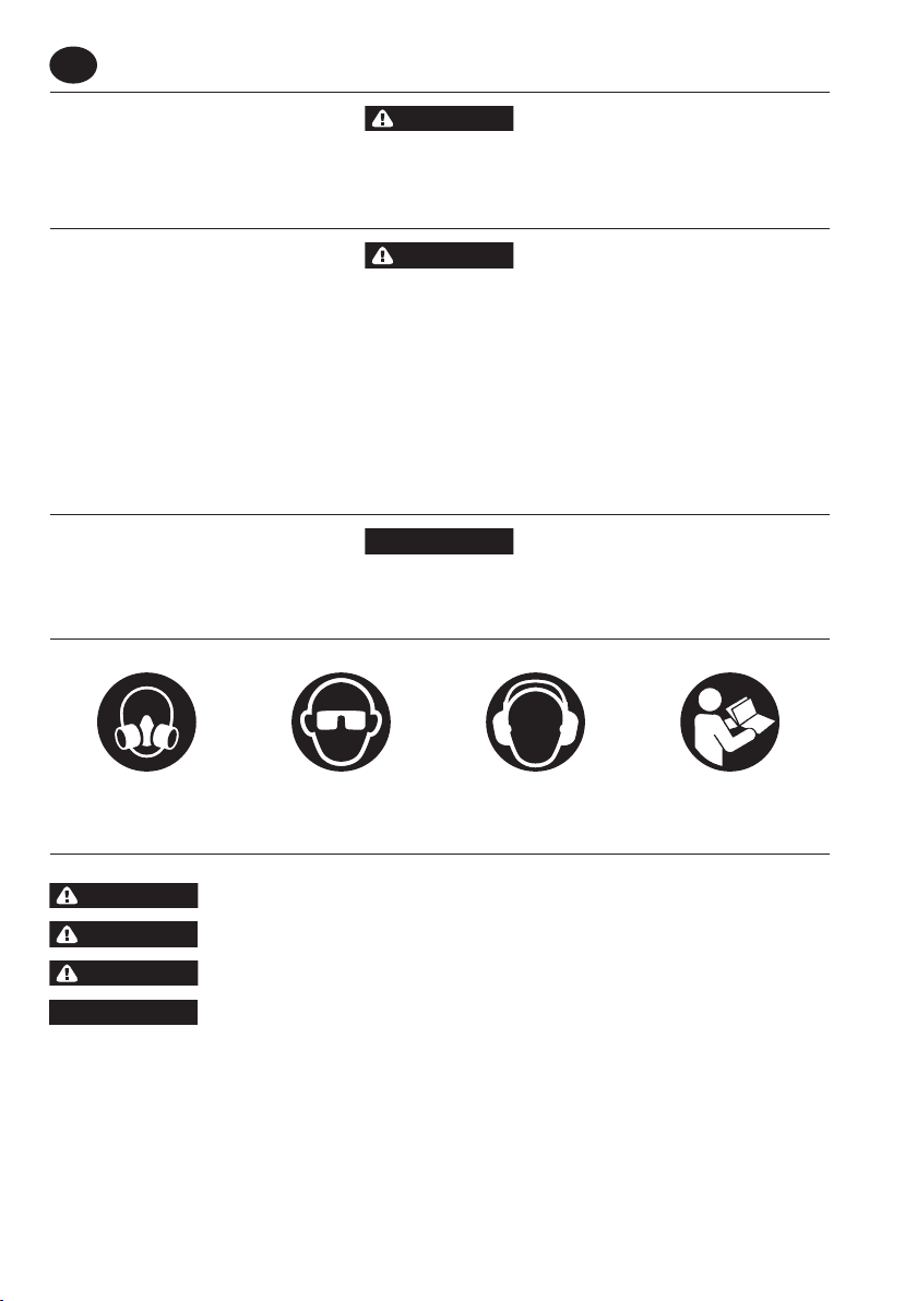
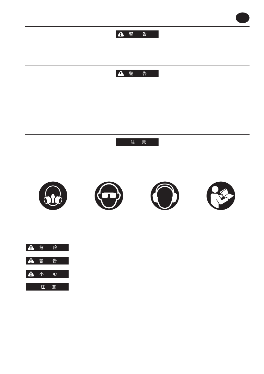
Safety Symbol Identi cation
NOTICE
Wear Respiratory
Protection
(Dwg. MHP2598)
Wear E ye
Protection
Wear Hearing
Protection
Read Manuals Before
Operating Product
Safety Information - Explanation of Safety Signal Words
DANGER
WARNING
CAUTION
NOTICE
Indicates an imminently hazardous situation which, if not avoided, will result in death or serious injury.
Indicates a potentially hazardous situation which, if not avoided, could result in death or serious injury.
Indicates a potentially hazardous situation which, if not avoided, may result in minor or moderate injury or
property damage.
Indicates information or a company policy that relates directly or indirectly to the safety of personnel or
protection of property.
2 03536968_ed5
Page 3
EN
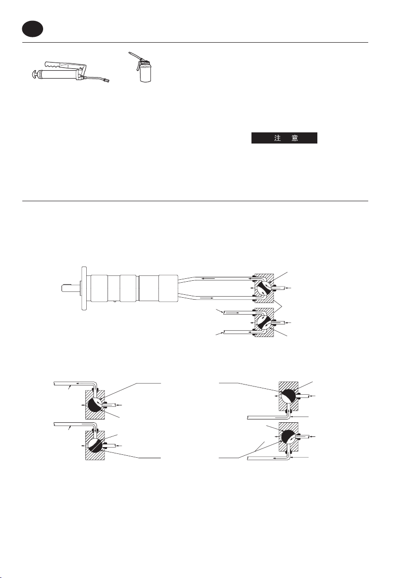
Lubrication
Ingersoll Rand No. 28 Ingersoll Rand No.10
Lubricant. Lubricant.
We recommend the use of an air line lubricator in the air supply line.
Attach the unit as close to the motor as practical. We recommend
using an Ingersoll Rand No. C28221-800 Filter-Regulator-Lubricator
Unit. After each forty hours of operation, or as experience indicates,
remove the Gear Case Grease Screw (23) and inject 1.5 cc of the
recommended grease into the opening. Do not grease excessively.
Too much grease in the Gear Case (16) will cause heating. Grease
leakage from the spindle end is also an indication that an excessive
amount of grease has accumulated within the Gear Case.
Whenever the gear end of the Motor is disassembled, lubricate the
gear train as follows:
For Gear ratio 000:1, work approximately 13 cc of the
recommended grease into and around the Spindle Bearing (26).
For gear ratios 004:1, 006:1 or 009:1, work approximately 26 cc of
the recommended grease into the gearing and around the Planet
Gear Bearings (20) and Spindle Bearings (26).
Operation
For optimum performance, the air source and supply lines must be
capable of maintaining 90 psig (6.2 bar/620 kPa) air pressure at the
Motor. 3/8” (9.5 mm) diameter or larger hose is necessary for ample
air ow to each Motor.
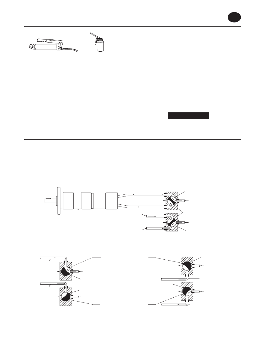
Reversible Motors require the use of a 4–way valve, or two 3–way
valves in the supply line because the reverse air inlet port becomes
an auxiliary port when the Motor operates in forward rotation. In
reverse, the forward inlet becomes the auxiliary exhaust port.
Air line to
forward inlet
Air line to
forward inlet
(Dwg. TPB854)
Reversible Motor
Single Four Way Valve for controlling Forward and Reverse operation of Motor
Relative positions of Valves for
Exhaust
Exhaust
Three-way Throttle Valve
in air line to
forward inlet
Two Three Way Valve for controlling Forward and Reverse operation of Motor
Live Air
Valve positioned for forward
operation of Motor
Valve positioned for reverse
operation of Motor
Live Air
Relative positions of Valves for
forward inlet
reverse inlet
forward operation of Motor
reverse operation of Motor
For gear ratios 012:1, 015:1, 021:1, 027:1, 037:1, 044:1, 063:1 and
086:1, work approximately 34 cc of the recommended grease into
the gearing and around the Planet Gear Bearings (20) and (49) and
Spindle Bearings (26).
For gear ratios 063:1, 086:1, 119:1, 151:1, 188:1, 275:1
and 374:1, work approximately 45 cc of the recommended grease
into the gearing and around the Planet Gear Bearings (20), (42) and
(38) and Spindle Bearings (26), (34) and (35).
For continuous operation:
Continuous operation of geared motors generates heat which
can cause grease to dry out and cake. The addition of fresh grease
temporarily recti es this problem. However, a small amount of oil
should be added to the grease to replace the oil which was lost
during continuous operation. The oil creates a slurry which makes
the grease less likely to dry out and cake. After each eight hours of
continuous operation or as experience indicates, add ten drops
of the recommended oil to the opening of each grease screw or
grease tting.
NOTICE
The use of other than genuine Ingersoll Rand replacement
parts may result in decreased tool performance and increased
maintenance, and may invalidate all warranties.
An example of each method is diagrammed in the following
illustration.
Valve positioned for
Forward Inlet
Exhaust
Reverse Inlet
Air line to
Air line to
Valve positioned for reverse
Exhaust
operation of Motor
Exhaust
Exhaust
Three-way Throttle Valve
forward operation
Live Air
Four- way
Throttle
Valve
Live Air
Valve positioned for
reverse operation
in air line to
reverse inlet
of Motor
of Motor
Valve positioned for
forward operation
of Motor
Live Air
Air line to
reverse inlet
Live Air
Air line to
reverse inlet
03536968_ed5 3
Page 4
EN
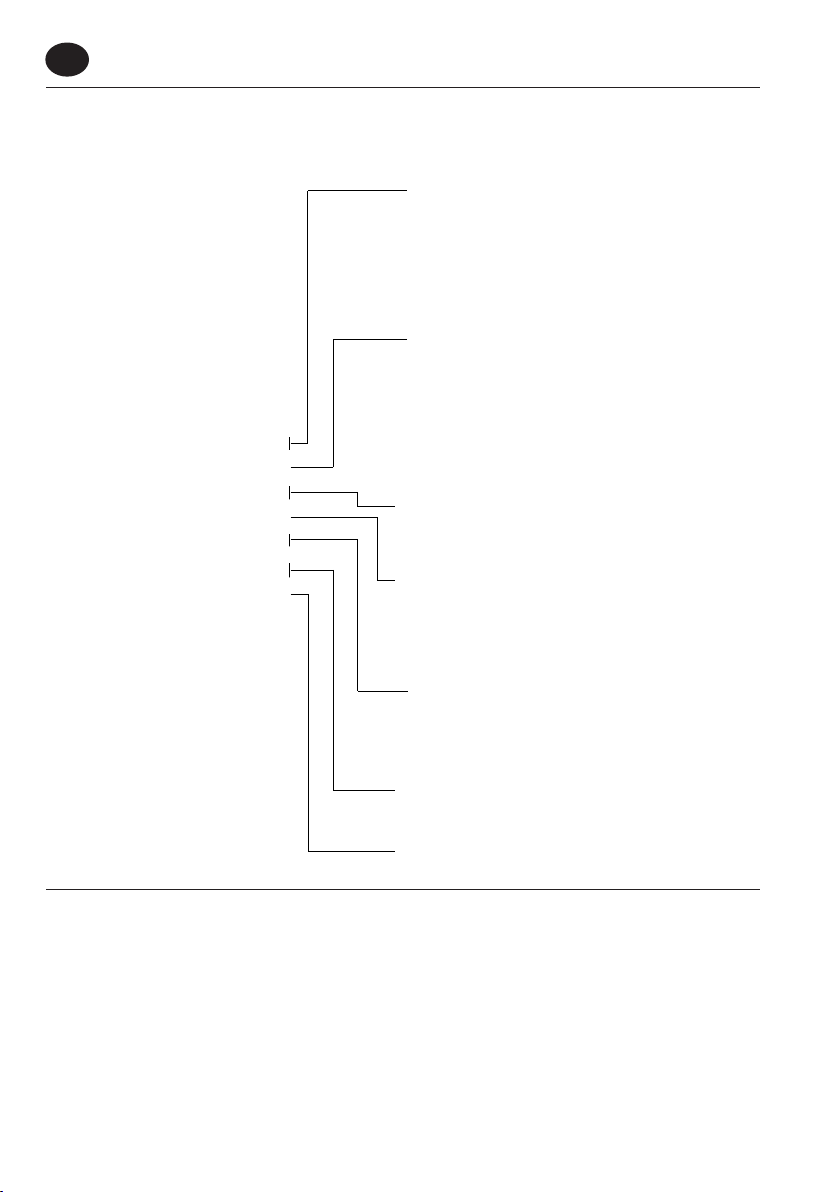
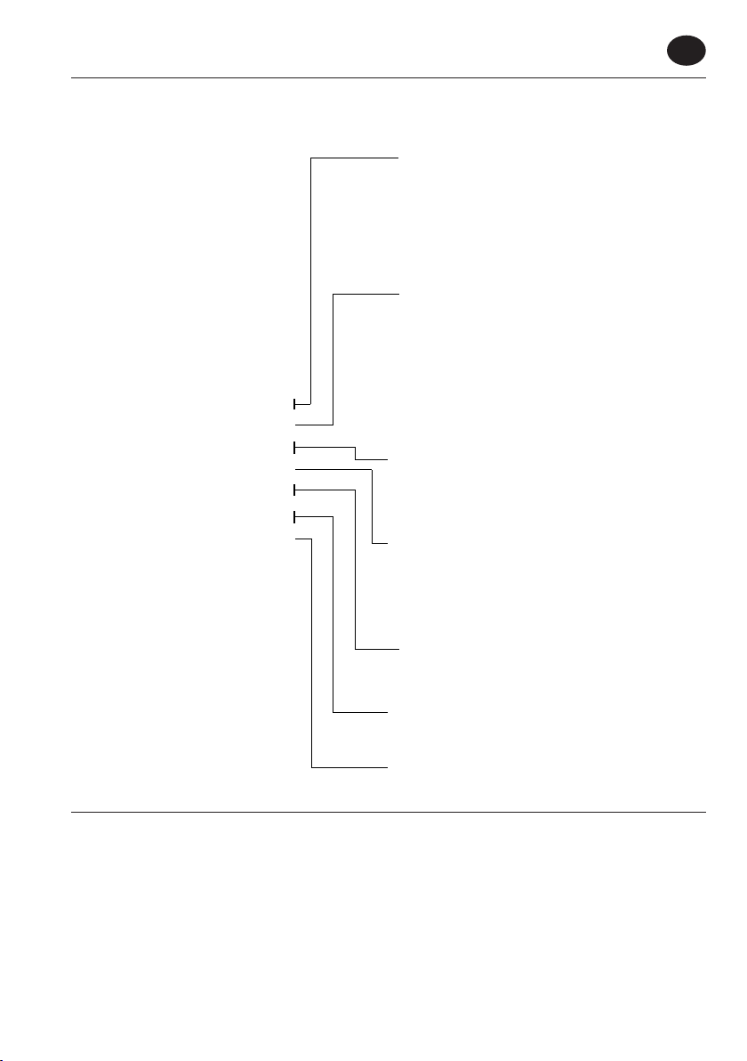
Model Number Code for M007 Stationary Air Motor
R4
Shaft
R4 = 1/2" Round Keyed
R6 = 3/4" Round Keyed
S4 = 1/2" Square Drive
S5 = 5/8" Square Drive
T3 = 3/8"-24 Threaded
Flange
A = 2 Hole Flange
B = 4 Hole Face Mount
B = 6 Hole Face Mount
(on M007 Motors with 063,
086, 119, 151, 188, 275 and
374 Gear Ratios)
027 A
R
RV
007
M
(Dwg. TPD1207)
Gear
Ratio
000 = Direct Drive
R = Rear
Air Inlet
and Exhaust
Rotation
RV (Reversible)
Nominal
Horsepower
007 (.61 to .85)
M
Basic
Model
086 = 86 : 1
374 = 374 : 1
etc.
S = Side
RH ( NR, CCW Facing Shaft)
LH (NR, CW Facing Shaft)
(Consult Current Air
Motor Catalog for Complete
List of Ratios by Model)
Parts and Maintenance
When the life of the motor has expired, it is recommended that the motor be disassembled, degreased and parts be separated by material so
that they can be recycled.
Manuals can be downloaded from www.ingersollrandproducts.com
Refer all communications to the nearest Ingersoll Rand O ce or Distributor.
4 03536968_ed5
Page 5
通用产品安全信息
■
使用产品前请阅读并理解本手册。
■
您有责任为其他操作该产品的人员提供本安全手册。
■
不按照以下警告进行操作将可能导致人员受伤。
•
请始终按照美国国家标准协会移动式空气工具安全标准 (ANSI B186.1) 使用、检查和维护该电机。
•
为确保使用安全、最佳性能、零部件的最长使用寿命,电机使用气压为 90 psig (6.2 bar/620kPa),气源软管规格为 5/16”(8mm)。
•
请务必在安装、移动或更换电机部件、或进行任何维修之前关闭并切断气源。
•
切勿使用已损坏、磨损或老化的空气软管及其它连接装置。
•
禁止手、散布、长发人员靠近电机旋转端。
•
请留心和注意电机启动和旋转过程中出现的运转异常变化。
•
气阀松开后电机轴仍会旋转。
•
请勿使用易燃易爆液体如煤油、柴油或喷气机燃料作为润滑油。
•
请勿撕掉任何标签。 请更换任何受损的标签。
•
使用 Ingersoll Rand 推荐配件。
•
该电机的设计决定了其不适用于爆炸性气体。
•
该电机没有防电击功能。
•
除 Ingersoll Rand 原装更换部件外,更换其它部件可能会导致安全危险、设备电机降低、维护工作增加,而且可能导致所有保修失
效。
•
用户若没有咨询 Ingersoll Rand 而擅自根据使用场合对工具进行改动,Ingersoll Rand 将不对其产生的后果负任何责任。
•
维修须由授权并经过培训的专业人员进行。 咨询您最近的 Ingersoll Rand 授权维修中心。
•
雇主应将本手册相关信息准确传达给操作人员。
安全标识识别。
ZH
戴呼吸保护器
保护。
(图 MHP2598)
戴眼镜
保护。
戴听力保护器
保护。
先阅读手册
操作产品
安全信息:安全信号文字解释
表示如果不避免,可能出现紧急危险情况导致死亡或重伤。
表示如果不避免,可能出现紧急危险情况,可能导致死亡或重伤。
表示如果不避免,可能出现紧急危险情况,可能导致人员轻度或重度受伤或财产损失。
表示直接或间接与人身安全和财产保护有关的信息或公司政策。
03536968_ed5 5
Page 6
ZH
润滑油
Ingersoll Rand 28 号 Ingersoll Rand 10 号
润滑油。 润滑油。
我们建议在供气管线中使用气管润滑剂。 请根据实际情况尽量
靠近电机安装润滑器。 我们建议使用 Ingersoll Rand 部件号
C28221-800 过滤器-调节器-润滑器装置。每工作 40 小时后,或根
据经验判断需要时,请卸下齿轮箱润滑油螺钉 (23),在开口中注
入 1.5 毫升的推荐油脂。 切勿润滑过度。 齿轮箱 (16) 中油脂太
多可能导致过热。
如果轴端有油脂渗出,也表示齿轮箱内的油脂过多。拆卸电机齿
轮端时,必须按照以下说明对齿轮链进行润滑:
对于传动比 000:1,在主轴承 (26) 内及周围注入大约 13 毫升的
推荐油品。
对于传动比 004:1、006:1 或 009:1、在行星齿轮轴承 (20) 和主轴
承 (26) 内及周围注入大约 26 毫升的推荐油品。
对于传动比 012:1、015:1、021:1、027:1、037:1、044:1、063:1 和
086:1,在行星齿轮轴承 (20) 和 (49) 以及主轴承 (26) 内及周围注
操作
要获得最佳的性能,气源和供气管线必须能够保持电机处 90 psig
(6.2 bar/620 kPa) 的气压: 必需 3/8” (9.5 mm) 或更大直径的软管
才能保证每个电机具有充足的气流:
可逆电机需要在供气管线中使用一个 4 通阀门或两个 3 通阀门,
因为电机正向旋转工作时,逆向进气口将成为辅助端口。 逆向工
作时,正向进气口将成为辅助出气口。
可逆电机
正转进口气管
反转进口气管
入大约 34 毫升的推荐油品。
对于传动比 063:1、086:1, 119:1、151:1、188:1、275:1 和 374:1,
在行星齿轮轴承 (20)、(42) 和 (38) 以及主轴承 (26)、(34) 和 (35)
内及周围注入大约 45 毫升的推荐油品。
对于连续运转:
齿轮电机的连续运转会产生热量,导致油脂变干和结块。 临时
添加新油脂可解决这个问题。 但是,应在油脂中添加少量的润
滑油,以补充连续运转过程中损失的润滑油。 润滑油可与油脂
混合,缓解其变干结块的问题。 连续运转 8 小时后或根据经验
判断需要时,请在每个油脂螺钉或油脂装置的开口中注入 10 滴
推荐润滑油。
使用非 Ingersoll Rand 原装更换部件可能会导致工具性能降低和
维护工作增加,而且可能导致所有保修失效。
下图详细描述了每种方法的工作方式。
正转进口
排气
反转进口
排气
电机正转阀
流动空气
四通节流阀
流动空气
电机反转阀
一个控制电机正转和反转的四通阀
电机正转阀
流动空气
反转进口气管
流动空气
反转进口气管
正转进口气管
排气
正转进口气管
排气
正转进口气管三通节流阀
流动空气
电机正转阀
电机反转阀
流动空气
电机正转相对阀位
排气
电机反转阀
排气
电机反转相对阀位
反转进口气管三通节流阀
两个控制电机正转和反转的三通阀
(图 TPB854)
6 03536968_ed5
Page 7
M007 固定型空气电机的型号代码
R4
027 A
R
RV
007
M
轴
R4 = 1/2" 圆键
R6 = 3/4" 圆键
S4 = 1/2" 四方传动
S5 = 5/8" 四方传动
T3 = 3/8"-24 螺纹
法兰
A = 2 孔法兰
B = 4 孔正面安装
B = 6 孔正面安装
(在传动比为 063、086、
119、151、188、275
和 374 的 M007 电机上)
传动比:
000 = 直接驱动
086 = 86 : 1
374 = 374 : 1╬╬(有关各型号传动比的完整列表,
请查阅目前的空气电机目录)
R = 后方
S = 侧面
空气进口和出口
ZH
旋向
RV (可逆)
RH ( NR, CCW 面向轴)
LH (NR, CW 面向轴)
额定功率
007 (.61 to .85)
M
(图 TPD1207)
基本型号
部件和维护
电机寿命到期后,建议将其拆卸并除去所有油脂,将部件按材料归类,以便回收利用。
手册可从 www.ingersollrandproducts.com 下载。
如有任何事宜,请垂询就近的 Ingersoll Rand 办事处或经销商。
03536968_ed5 7
Page 8
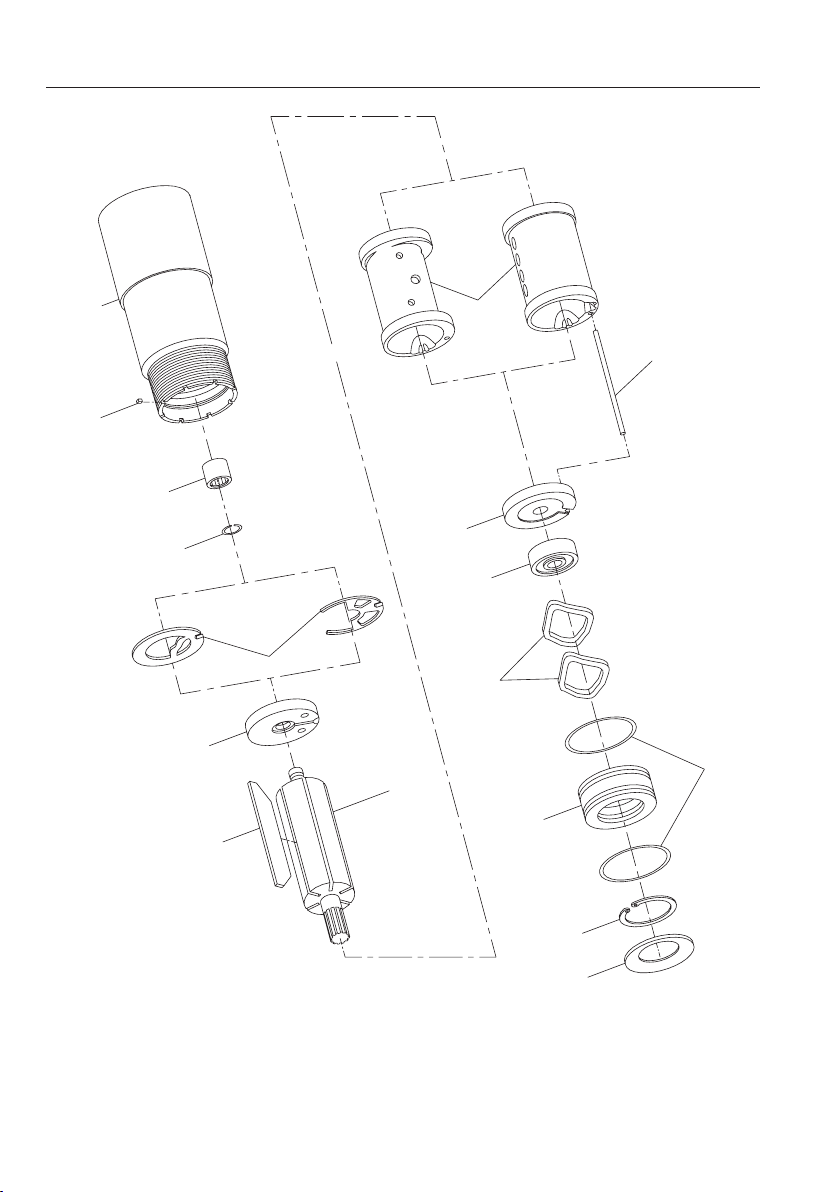
M007 Series Motor Power Unit Exploded Diagram
models
1
reverse rotation shown
For Non Reversible models -
58
3
2
4
5
6
7
8
11
12
13
10
For Reversible
9
10A
14
(Dwg. TPB847)
8 03536968_ed5
15
Page 9
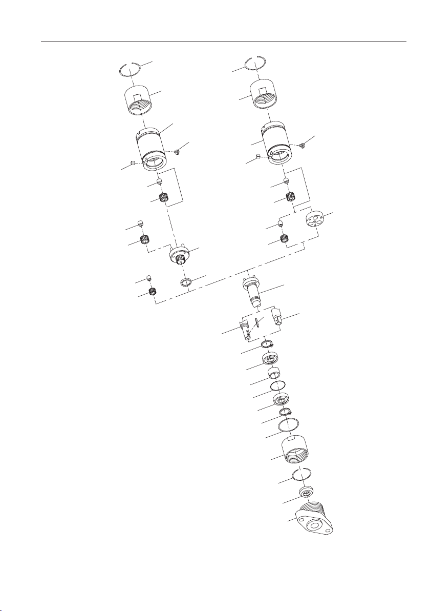
M007 Series Spindle, Gear Case and Gearing for 000, 004, 006, 009, 012, 015, 021, 027, 037 and 044 Ratios
25
25
24
24
16
23
012, 015, 021, 027, 037 or 044
For Gear ratios
58
23
000, 004, 006 or 009
For Gear ratios
16
58
22
21
49
48
20
19
ratio only
For 012 or 015
47
46
17
22
21
20
19
17
59
29
26
27
28
26
29
56
24
ratio only
For 004
18
ratio only
For 000 Gear
17
25
57
55
(Dwg. TPA1230)
03536968_ed5 9
Page 10
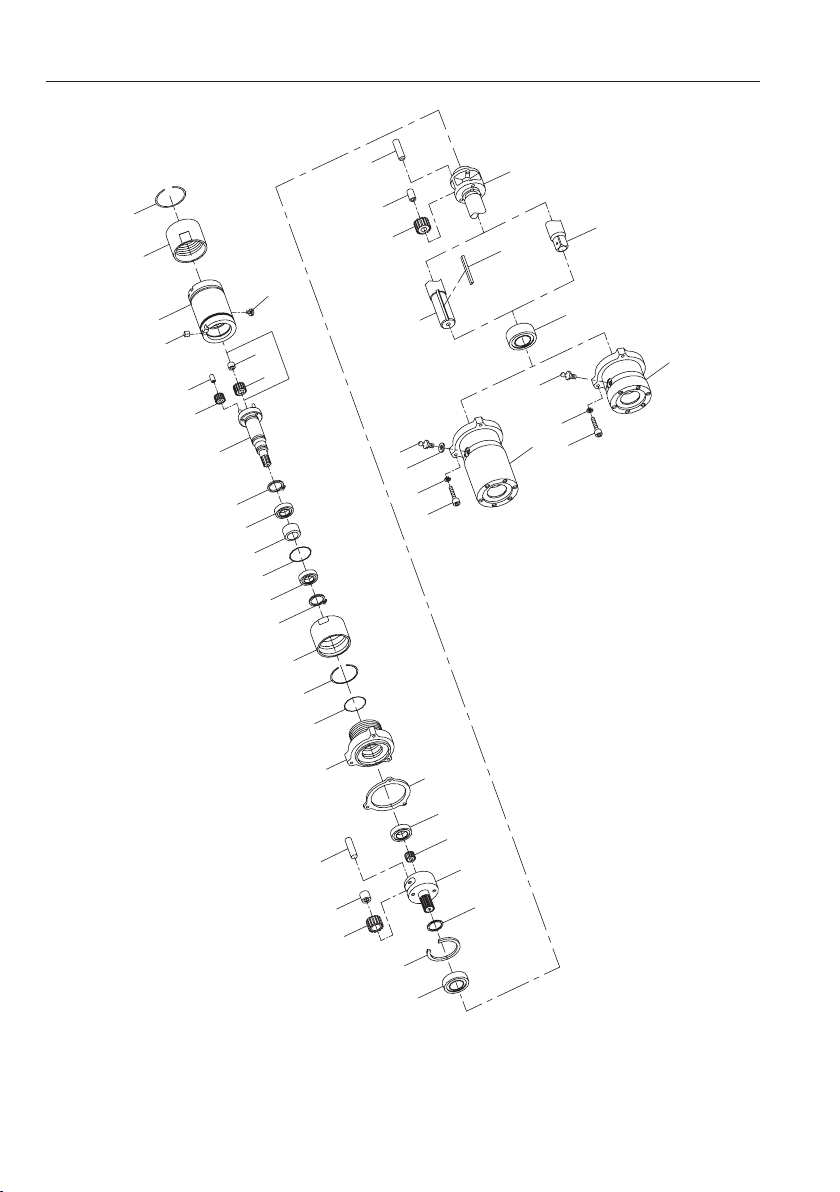
M007 Series Spindle, Gear Case and Gearing for 063, 086, 119, 151, 188, 275 and 374 Ratios
36
25
24
23
16
58
20
19
17A
22
21
For 188
ratio only
29
26
27
28
26
29
24
25
51
38
37
33
32
31
54
53
33
59
32
54
30
53
For 119, 151, 275
and 374 ratio only
33
35
30
For 063 and 086
ratio only
50
44
42
41
(Dwg. TPA1229-1)
10 03536968_ed5
52
45
For 119
ratio only
43
40
46
39
34
Page 11
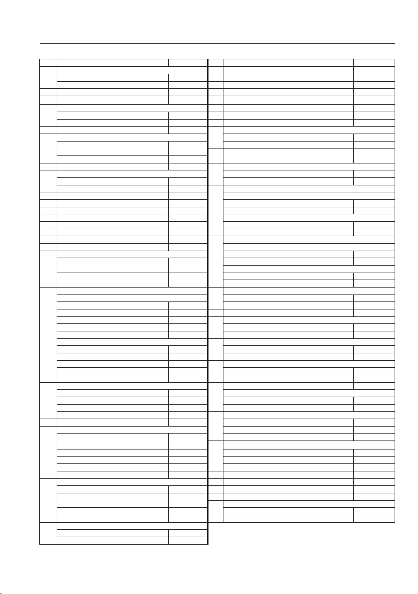
M007 Series Parts List
Item Part Description Part Number Item Part Description Part Number
1
Motor Housing 22 Rotor Pinion Spacer (for 004, 012, 015 or 188 ratio) 7AH-18
for nonreversible models M007-N40 23 Grease Screw M002-95
2 Rear End Plate Retainer 7AH-118 25 Coupling Nut Retainer (2) M007-29
3 Rear Rotor Bearing 7AH-24 26 Spindle Bearing (2) WFS182-97
4 Rear End Plate Gasket 27 Spindle Bearing Spacer M007-111
5 Rear End Plate M007-12 30 Gear Case Assembly
6 Rotor for 063 or 086 ratio ET3802M-A37
7 Vane Packet (set of 5 Vanes) 7RL-42-5 32 Grease Fitting
8 Cylinder for 063 or 086 ratio 23-188
9 Cylinder Dowel 7AH-98 Round keyed shaft
10 Rotor Bearing Housing Assembly M007-A13 for 063 or 086 ratio R3800M-A108
10A Rotor Bearing Housing Seal M007-210 for 119, 151, 188, 275 or 374 ratio R3800P-A108
11 Front End Plate M007-11 Square drive shaft
12 Front Rotor Bearing R1-22 for 063 or 086 ratio R3800M-A8
13 Front Rotor Bearing Spring Washer(2) 7AH-278 for 119, 151, 188, 275 or 374 ratio R3800P-A8
14 Front Rotor Bearing Retainer W22-118 33 Spindle
15 Motor Clamp Washer M007-207 Round keyed shaft
16 Gear Case for 063 or 086 ratio R3800M-108
17 Spindle 34 Rear Spindle Bearing
17A Driver 39 Spindle Retainer (for 119, 151, 188, 275 or 374 ratio) FMC2-280
18 Spindle Drive Plate (for 000 ratio only) 7AD-171 for 119 ratio (3) R38P-216
19 Spindle Planet Gear Assembly (3) for 151 ratio (2) R3800R2-216
20 Planet Gear Bearing (3) 43 Rotor Pinion (for 119 ratio only) R38P-17
21 Rotor Pinion
for reversible models M007-R40 24 Coupling Nut(2) M007-27
for nonreversible models 7AH-739 28 Gear Case Seal M007-210
for reversible models 7RL-739 29 Spindle and Spindle Bearing Retaining Ring (2) R380Q-6
for 006, 021, 027, 063, 119, or
275 ratios
for all other ratios M007-53-000 or 374 ratio)
for nonreversible models 7AH-3A for 119, 151, 188, 275 or 374 ratio R1-188
for reversible models M007-R3 Spindle Assembly
for 012, 015, 021, 027, 037
or 044 ratio Square drive shaft
for 000, 004, 006, 009, 063, 086,
119, 151, 188, 275 or 374 ratio for 119, 151, 188, 275 or 374 ratio R3800P-8
Round keyed shaft for 063 or 086 ratio 4E-510
for 000, 004, 015, 027 or 037 ratio M007-108-000 for 119, 151, 188, 275 or 374 ratio R38P-97
for 012 or 021 ratio M007-108-012 35 Front Spindle Bearing 4UA9-593
for 006 ratio M007-108-006 36 Planet Gear Shaft
for 009 ratio M007-108-009 for 063 or 086 ratio (2) 8U-191
for 044 ratio M007-108-044 for 119, 151, 188, 275 or 374 ratio (3) R38P-190
Square drive shaft 37 Planet Gear Assembly
for 000, 004, 015, 027 or 037 ratio M007-208-000 for 063 or 086 ratio (2) 4E-10A
for 012 or 021 ratio M007-208-012 for 119, 151, 188, 275 or 374 ratio (3) R38P-9
for 006 ratio M007-208-006 38 Planet Gear Bearing
for 009 ratio M007-208-009 for 063 or 086 ratio (2) 8U-654
for 044 ratio M007-208-044 for 119, 151, 188, 275 or 374 ratio (3) R38P-500
for 063, 119 or 275 ratio M007-563-063 Gear Head Assembly
for 086 or 374 ratio M007-563-086 for 119 ratio R38P-A216
for 151 ratio M007-563-151 for 188, 275 or 374 ratio R380S-A2l6
for 188 ratio M007-563-l88 40 Gear Head
for 004, 015, 027, 037, 151 or 188
ratio
for 006, 063, 119 or 275 ratio 7AK-A10 for 119 ratio (3) R38P-10
for 009, 086 or 374 ratio 7AL-A10 for 151 ratio (2) WBT380NL-A10
for 044 ratio 7AQ-A10 for 188, 275 or 374 ratio 4E-10A
for 012 or 021 ratio M007-A10-003 42 Planet Gear Bearing 8U-654
for 012 or 021 ratio 7AH-500 44 Planet Gear Shaft (2) 8U-191
for 004, 015, 027, 037, 044, 151
or 188 ratio 46 Gear Head Spacer
for 006, 009, 063, 086, 119, 275
or 374 ratio for 119, 188, 275 or 374 ratio R38P-80
for 012 or 015 ratio 7AH-17
for 004, 188 ratio or 151 ratio 7AJ-17
M007-53-006
M007-137
M007-37
7AJ-A10
7AJ-500
7AK-500
31
41
45 Gear Head Bearing 4E-510
for 119, 151, 188, 275 or 374 ratio ET3802P-A37
Grease Fitting Washer (for 119, 151, 188, 275
for 119, 151, 188, 275 or 374 ratio R3800P-108
for 063 or 086 ratio R3800M-8
for 188, 275 or 374 ratio R380S-216
Gear Head Planet Gear Assembly
for 012, 015, 021, 027, 037 or 044 ratio 7AN-80
R3-92A
03536968_ed5 11
Page 12
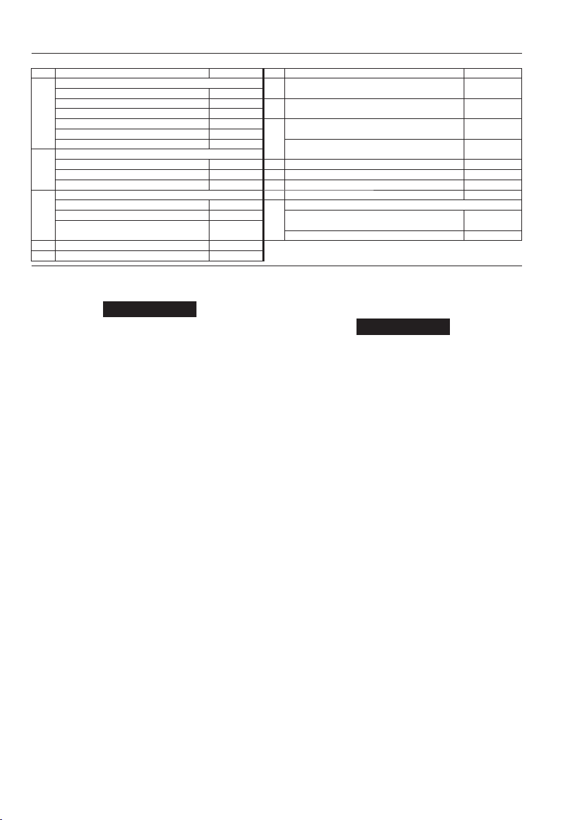
M007 Series Parts List
Item Part Description Part Number Item Part Description Part Number
47 Gear Head
48
49
50 Gear Case Adapter M007-100
51 Gear Case Adapter Seal M007-210
for 012 ratio M007-216-012 (for 119, 151, 188, 275 or 374 ratio)
for 015 ratio M007-216-01553Auxiliary Gear Case Cap Screw (3)
for 021 ratio M007-216-021 (for 119, 151, 188, 275 or 374 ratio)
for 027 ratio M007-216-027 54 Auxiliary Gear Case Lock Washer (3)
for 037 ratio M007-216-037 (for 119, 151, 188, 275 or 374 ratio)
for 044 ratio M007-216-044 Flange Assembly (for 000, 004, 006, 009, 012, 015,
Gear Head Planet Gear Assembly (3) 021, 027 or 044 ratio)
for 012 or 015 ratio M007-A10-003 55 Flange M007-580
for 021 or 027 ratio 7AK-A10 56 Flange Seal M007-210
for 037 or 044 ratio 7AL-A10 57 Spindle Seal M007-271
Planet Gear Bearing (3) 58 Flange Key (2) M007-561
for 012 or 015 ratio 7AH-500
for 021, 027, 037 or 044 ratio 7AK 500 for 063, 086, 119, 151, 188, 275 or 374
Gear Case Adapter (for 119, 151, 188, 275
or 374 ratio) (Includes Items 50 and 51) for all other ratios 501-410
M007-A100
Maintenance Section
Disassembly
NOTICE
Always disconnect the air supply before doing any maintenance
on this Motor. Always use protective eyewear when performing
maintenance on a tool or when operating a tool.
General Instructions
1. Do not disassemble the motor any further than necessary to
replace or repair damaged parts.
2. Do not disassemble the motor unless you have a complete set of
new gaskets and O-rings for replacement.
3. Do not remove any part which is a press t in or on a
subassembly unless the removal of that part is necessary for
repairs or replacement.
4. Whenever grasping a motor or part in a vise, always use leathercovered or copper-covered vise jaws to protect the surface of the
part or motor and help prevent distortion. This is particularly true
of threaded members and housings.
5. The modular construction of the Series M007 Motors permits
selective disassembly whereby gearing can be separated
from the power unit and disassembled without removing the
Multi–Vane® Motor from the Motor Housing, or the Multi–Vane®
Motor can be removed and disassembled without removing the
gear train from the gear chambers. This is especially true for the
high torque ratios that use a Gear Case Adapter and Auxiliary
Gear Case. Because of the modular construction, the steps in the
following Disassembly Procedures can be sequentially changed
to meet the particular situation.
6. When removing a Planet Gear Shaft, always support the rear
(short hub end) of the Gear Head, Gear Frame or Spindle and
press on the front end of the Shaft being removed. The shaft
holes through the webs are slightly tapered so that the Shaft is a
tighter t in the front web.
7. Do not press any needle bearing from a part unless you have a
new needle bearing on hand for installation. Needle bearings are
always damaged during the removal process.
Disassembly of the Motor
1. Clamp a large adjustable wrench in vise jaws with the adjustable
opening upward.
2. Adjust the jaw of the wrench to clear the body of the Gear Case (16).
3. Roll the Motor in the wrench jaw until it stops against the Gear
Case Screw (23) and using a wrench on the ats of the Coupling
Nut (24) at the motor end; loosen the Coupling Nut.
4. Roll the Motor in the opposite direction until it stops against the
Grease Screw and using a wrench on the ats of the Coupling Nut
at the ange end of the Gear Case, loosen the Coupling Nut.
5. Holding the Motor horizontally over a workbench, unscrew the
Coupling Nut at the motor end of the Gear Case and pull the
motor from the Gear Case. Do not lose the Flange Key (58).
12 03536968_ed5
Auxiliary Gear Case Front Gasket
52
59
Spindle Key (for Round Keyed Spindles only)
ratio
6. For 000, 004, 006, 009, 012, 015, 021, 027, 037 or 044 ratio, to
remove the Flange Assembly without removing the Spindle (17),
unscrew the Coupling Nut and while pushing the Spindle inward,
slide the Flange Assembly o the Spindle.
R1602-250
510-638
M007-A580
P25-150
NOTICE
If the Spindle is removed, the entire gear train must be
disassembled to install the Spindle Planet Gear Assemblies (19)
or Gear Head Planet Gear Assemblies (48).
a. Remove the Spindle Seal (57) from the Spindle. Remove the
Flange Seal (56) from the inside of the Flange (55).
b. Grasp the shaft of the Spindle and pull it from the Gear Case.
c. Using snap ring pliers, remove the Spindle Retaining
Ring (29) and pull the two Spindle Bearings (26) and the
Spindle Bearing Spacer (27) from the shaft of the Spindle.
Remove the second Spindle Retaining Ring.
7. For 000 ratio, pull the Spindle DrivePlate (18) from the Gear Case.
For 004 ratio, pull the Rotor Pinion (21), Rotor Pinion Spacer
(22) and the three Spindle Planet Gear Assemblies (19) from the
Gear Case. For 012 or 015 ratio, pull the Rotor Pinion (21), Rotor
Pinion Spacer, three Gear Head Planet Gear Assemblies (48), Gear
Head (47) and Gear Head Spacer (46) from the Gear Case.
For 021,027,037 or 044 ratio, pull the three Gear Head Planet
Gear Assemblies (48), Gear Head (47) and Gear Head Spacer (46)
from the Gear Case.
8. For 063, 086, 119, 151, 188, 275 or 374 ratio, loosen the
Coupling Nut (24) at the front of the Gear Case (16) and separate
the Gear Case from the Gear Case Adapter (50).
a. Pull the Spindle (17) from the front of the Gear Case.
b. For 188 ratio, pull the Rotor Pinion (21), Rotor Pinion
Spacer (22) and Spindle Planet Gear Assembly (19) from the
Gear Case.
c. For 063, 086, 119, 151, 275 or 374 ratio, pull the Spindle
Planet Gear Assembly (19) from the Gear Case.
d. Using snap ring pliers, remove the Spindle Bearing Retaining
Ring (29) and pull the two Spindle Bearings (26) and the
Spindle Bearing Spacer (27) from the shaft of the Spindle.
Remove the second Spindle Retaining Ring.
e. Remove the Gear Case Adapter Seal (51) from the Gear Case
Adapter (50).
f . Remove the Auxiliary Gear Case Cap Screws (53) and Lock
Washers (54) from the Auxiliary Gear Case and separate the
Auxiliary Gear Case and components from Gear Case Adapter.
g. Withdraw the Gear Head (40) and the assembled components
from the rear of the Auxiliary Gear Case.
h. Supporting the hub of the Gear Head, press on the front end
of the Planet Gear Shaf t to remove the Shaft and Planet Gears.
For 119 ratio, remove the Rotor Pinion (43) from the Gear Head.
8U-58
Page 13

i. Using care to prevent unnecessary distortion, pry the
Spindle Bearing Retainer (39) from the wall of the Auxiliary
Gear Case and slide out the Spindle (33) and the assembled
components.
j. Remove Gear Head Planet Gears if worn. See paragraph “h”.
9. Using a thin blade screwdriver, pry one of the Coupling Nut
Retainers (25) out of the groove in the Gear Case and slide the
two Coupling Nuts o the Gear Case.
10. Grasp the shaft of the Rotor (6) in copper-covered vise jaws and
pull the Motor Housing (1) o the assembled motor unit.
11. Pull the Front End Plate (11) o the Rotor.
12. Remove the Front Rotor Bearing Retainer (14), Rotor Bearing
Housing Assembly (10), Front Rotor Bearing Spring Washers Front
Rotor Bearing (12) and Front End Plate. Remove the Rotor Bearing
Housing Seals (10A) from the Rotor Bearing Housing.
13. Push the Front Rotor Bearing out of the Front End Plate.
14. Separate Cylinder (8), Vanes (7) and Cylinder Dowel (9) from the Rotor.
Remove the Rear End Plate Gasket from inside the Motor Housing.
15. Remove the Rear End Plate Retainer (2) and Rear End Plate (5)
from the Rotor.
Assembly
General Instructions
1. Always use protective eyewear when performing maintenance
on a tool or operating a tool.
2. Unless otherwise noted, always press on the stamped end of a
needle bearing when installing the needle bearing in a recess.
3. Always press on the inner ring of a ball-type bearing when
installing the bearing on a shaft.
4. Always press on the outer ring of a ball-type bearing when
installing the bearing in a bearing recess.
5. Check every bearing for roughness. If an open bearing must be
cleaned, wash it thoroughly in clean solvent and dry with a clean
cloth. Sealed or shielded bearings should never be cleaned. Work
grease thoroughly into every open bearing before installation.
6. Except for bearings, always clean every part and wipe every part
with a thin lm of oil before installation.
7. When grasping a Motor or one of its parts in a vise, always use
leather or copper vise jaw covers to protect the surface of the
part and reduce the likelihood of damage. This is particularly
important when clamping threaded members, shafts with
splines, etc.
8. Apply O-ring lubricant to each O-ring before assembly and use
only new gaskets when reassembling the Motor.
9. When installing Planet Gears in a Spindle, Gear Head or Gear Frame,
always support the front web and press in the shaft from rear to
front. Shaft holes through the webs are slightly tapered so that
shaft is tighter in front web. Always replace Planet Gears in sets.
10. Remember that the Rotor Pinion (43) used in the 119 ratio must
be entered in the Gear Head (40) before the second Planet
Gear (41) is installed.
Assembly of the Motor
1. Using a bearing inserting tool, press the Rear Rotor Bearing (3)
into the recess in the rear of the Motor Housing (1).
NOTICE
Press on marked end of bearing only. Unmarked end of Bearing
must be installed toward rear of Motor Housing.
2. Install Rear End Plate Gasket (4) in Motor Housing. Make certain
all hubs and porting align.
3. Slide the Front End Plate (11), at side rst, over the splined end
of the Rotor (6).
4. Using a sleeve that contacts only the inner ring of the Front Rotor
Bearing (12), press the Front Rotor Bearing onto the splined hub
of the Rotor until it seats against the Front End Plate.
5. The clearance between the Front End Plate and the Rotor is
critical. While holding the Front End Plate, gently tap the splined
end of the Rotor until you can insert a 0.001” feeler gauge or shim
between the face of the Rotor and Front End Plate.
6.
Grasp the splined end of the rotor in copper-covered vise jaws so
that the short hub of the rotor is upward.
7. Wipe each Vane (7) with a lm of light oil and place a Vane in each
vane slot in the Rotor.
8. For reversible models, align the Cylinder Dowel hole in the
Cylinder (8) with the hole in the Rear End Plate and install the
Cylinder over the Rotor and Vanes against the End Plate.
For nonreversible models, the installation of the Cylinder (8)
determines the rotational direction of the motor. Looking past
the rotor body and vanes, align the Cylinder Dowel hole in the
Rear End Plate at twelve o’clock. There are ve holes drilled
crosswise into the Cylinder. Align the cylinder dowel hole in
the Cylinder with the hole in the Rear End Plate and install the
Cylinder over the Rotor and Vanes against the Rear End Plate. If
the ve drilled holes are at the three o’clock side of the assembly,
the rotational direction will be forward (right hand). Rotational
direction will be reverse (left hand), if the holes are at the nine
o’clock side of the assembly. To change rotational direction,
remove the Cylinder, turn it end for end and reposition it in the
assembly. Nonreversible Cylinders have a 45 raised shoulder at
one end of the ve hole pattern. When the shoulder is near the
Rear End Plate, rotation will be reverse; when near the Front End
Plate, rotation will be forward.
9. Place the Rear End Plate (5), at side rst, over the short hub of
the Rotor.
10. Install the Rear End Plate Retainer (2) in the groove in the Rotor
hub.
11. Align the Cylinder Dowel holes in the Front End Plate, Cylinder
and Rear End Plate and insert an Assembly Dowel (3/32” [2.5 mm]
diameter by 9” [230 mm] long) into the aligned Dowel Holes in
the assembly.
12. Inject 2 cc of the recommended grease into the central recess at
the bottom of the bore in the Motor Housing (1).
13. For reversible models, insert the end of the Assembly Dowel
nearest the Rear End Plate into the Dowel Hole at the bottom of
the motor bore in the Housing. Slide the assembled motor along
the Assembly Dowel until the motor stops against the bottom
of the motor bore. Carefully withdraw the Assembly Dowel and
install the Cylinder Dowel (9) in its place. Make certain the Dowel
is below the face of the Front End Plate. For nonreversible
models, insert the end of the Assembly Dowel nearest the Rear
End Plate into one of the Dowel Holes at the bottom of the motor
bore in the Housing. With the inlet Hole at twelve o’clock and the
two Cylinder Dowel Holes at eleven and one o’ clock respectively,
inserting the Assembly Dowel in the one o’clock Hole will orient
the motor for forward (right hand) rotation while inserting the
Assembly Dowel in the eleven o‘ clock Hole will orient the motor
for reverse (left hand) rotation. Slide the assembled motor along
the Assembly Dowel until the motor stops against the bottom
of the motor bore. Carefully withdraw the Assembly Dowel and
install the Cylinder Dowel (9) in its place. Make certain the Dowel
is below the face of the Front End Plate.
14. Install the Front Rotor Bearing Retainer (14) in the groove inside
the Rotor Bearing Housing (10).
15. Install the two Rotor Bearing Housing Seals (10A) in the annular
grooves around the Rotor Bearing Housing.
16. Place the two Front Rotor Bearing Spring Washers (13) inside the
Front Rotor Baring Housing and against the Front Rotor Bearing
Retainer.
17. Slide Front Rotor Bearing Housing over the Front Rotor Bearing.
18. Install a Coupling Nut Retainer (25) in one of the grooves
encircling the Gear Case (16).
19. Position the non–threaded ends of the two Coupling Nuts (24)
against each other and slide them onto the Gear Case from the
end without the Retainer.
20.
Install the second Retainer in the remaining groove encircling the
Gear Case.
21.
Using snap ring pliers, install one of the Spindle Retaining Rings (29)
in the annular groove on the Spindle (17) adjacent to the large hub.
22. In the order named, install a Spindle Bearing (30), Spindle Bearing
Spacer (27) and the remaining Spindle Bearing on the spindle
shaft against the Spindle Retaining Ring. Secure the three parts
by installing the remaining Ring in the groove on the shaft.
23. Insert the pin end of the Spindle into the unsplined end of the
Gear Case and push the large spindle hub against the spline.
03536968_ed5 13
Page 14
Assembly of the Gearing
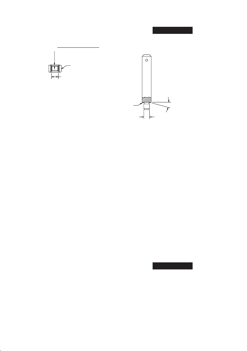
1. If the Planet Gear Bearings (20 or 49) are being replaced in the
Planet Gear Assemblies (19 or 48), use a bearing inserting tool
similar to the one shown and press the Bearings into the Gears.
Shoulder length =
gear length - bearing length
2
Assembled Planet Gear
Shoulder diameter
Always press on the stamped end of the Bearing and center the
NOTICE
Bearing in the Gear.
(Dwg. TPC488)
2.
For 004, 012, 015 or 188 ratio, install the Rotor Pinion Spacer
(22) and Rotor Pinion (21) on the Rotor (17). For 000 ratio, insert
the Drive Plate (18) into the splined end of the Gear Case. Make
certain the spindle pins enter the holes in the Drive Plate. For all
other ratios, push a Spindle Planet Gear Bearing (20) into each
Spindle Planet Gear (19) and using long tweezers, install a Bearing
and Gear on each spindle gear shaft. For 012, 015, 021, 037 or
044 ratio, install the Gear Head Spacer (46) against the Spindle
Planet Gears. Push a Planet Gear Bearing (49) into each Gear Head
Planet Gear (48). Install the assembled Gear Head Planet Gears
with Planet Gear Bearings on the Gear Head (47). Install the Gear
Head with assembled components in the Gear Case.
3. Place the Motor Clamp Washer (15), concave end leading, against
the Planet Gears or Drive Plate.
4. Being careful that the Spindle does not move out of position,
engage the gear case gearing with the splined shaft of the Rotor.
5. Align the Gear Case with the Motor Housing by installing a Flange
Key (58) to enter the notches in both the Housing and Gear Case.
Hand tighten the Coupling Nut onto the Motor Housing.
6. Lubricate the Spindle Seal (5) with a thin coat of Ingersoll Rand
No. 28 Grease and insert it, lip end trailing, into the threaded end
of the Flange (55).
7. Insert the Flange Seal (56) into the groove inside the threaded
end of the Flange.
a. Being careful not to damage the Spindle Seal, install the
Flange Assembly, threaded end rst, over the Spindle and
against the Gear Case.
b.
Align a notch in the Flange with a notch in the Gear Case and
maintain the alignment by installing a Flange Key in the two
notches.
c. Thread the Coupling Nut onto the Flange until it is hand tight.
8. For 063,086,119,151,188, 275 or 374 ratio, install the Gear Case
Adapter Seal (51) on Gear Case Adapter (50).
a. Align a notch in the Gear Case Adapter with a notch in the
Gear Case and maintain alignment by installing a Flange
Key (58) in the notches.
9. Thread the Gear Case Grease Screw (28) into the Gear Case, if it
was removed, and hand tighten it with a hex wrench.
10. Clamp a large adjustable wrench in vise jaws with the adjustable
opening upward.
11. Adjust the jaw of the wrench to clear the body of the Gear Case.
12. Roll the Motor in the wrench jaw until it stops against the Gear
Case Grease Screw and using a torque wrench on the ats of one
Coupling Nut, tighten the Nut between 45 to 50 ft–lb (61 to 68
Nm) torque.
Needle Bearing Tool for Planet Gears
Shoulder to
regulate depth
13. Roll the Motor in the opposite direction until it stops against the
Gear Case Grease Screw and using a torque wrench on the ats of
the second Coupling Nut, tighten the Nut between 45 to 50 ft-lb
(61 to 68 Nm) torque.
14. For 063, 086, 119, 151, 188, 275 or 374 ratio, install the Gear
Head Bearing (45) in the recess in the Gear Case Adapter.
a. For 119 ratio, install one Gear Head Planet Gear (41), one
Planet Gear Bearing (42) and one Planet Gear Shaft (44) in
the Gear Head (40). Install the Rotor Pinion (43) in the Gear
Head and then install the remaining Planet Gears, Planet Gear
Bearings and Planet Gear Shafts.
b. Press the Rear Spindle Bearing (34) on the rear of the Spindle
and Front Spindle Bearing (35) on the front of the Spindle.
c. Install the Spindle Planet Gears (37), Spindle Planet Gear
Bearings (38) and Spindle Planet Gear Shafts (39) on the
Spindle.
d. Install the assembled Spindle in the Auxiliary Gear Case (30)
meshing the Spindle Planet Gears with the integral ring gear.
e. Install the Spindle Bearing Retainer (39) in the annular groove
in the wall of the Auxiliary Gear Case.
f. Insert the Auxiliary Gear Case Cap Screws (53) and Lock
Washers (54) in the holes in the Auxiliary Gear Case. Position
the Auxiliary Gear Case Front Gasket (52) on the Cap Screws.
g. Join the Auxiliary Gear Case and Gear Case Adapter, making
sure that the splined end of the Spindle (17) meshes with the
Gear Head Planet Gears (151, 188, 275 or 374 ratio) or slides
into the Rotor Pinion (119 ratio). Secure Auxiliary Gear Case
and Gear Case Adapter by tightening the Gear Case Adapter
Cap Screws.
15°
Pilot to t I.D. of bearing.
Length of pilot to be approximately
1/8” less than length of bearing.
NOTICE
The rotor shaft must enter the Gear Head Planet Gears or Rotor
Pinion without force and the Rotor and Gear Frame Planet Gears
must turn freely without binding. The spline on the shaft of the
Gear Head must enter the Spindle Planet Gears without force
and the Gear Head and Spindle Planet Gears must turn freely
without binding. Using a hand torque wrench, turn the output
shaft. If the force required to turn the shaft exceeds 3-7 in-lb
(.339 to .791 Nm) torque, the gearing is improperly installed and
must be reassembled. See paragraphs “d” through ‘g”.
h. Install the Grease Fitting (32) and Grease Fitting Washer (31) in
the Auxiliary Gear Case.
14 03536968_ed5
Page 15
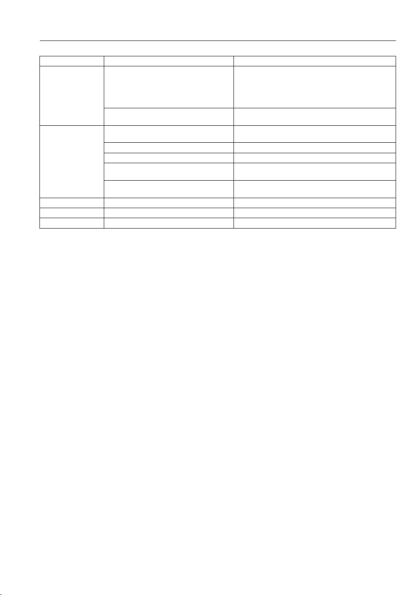
Troubleshooting Guide
Trouble Probable Cause Solution
Rotor shaft and Gear Frame Planet Gears (41)
binding due to improper installation.
Motor will not operate.
Spline in shaft of Gear Head (40) and Spindle
Planet Gears binding due to improper installation.
Low air pressure at Motor. Check air supply. For top performance, the air pressure must
Worn Vanes. Install a new set of Vanes (7).
Loss of power.
Motor heats up. Inadequate lubrication. Refer to Lubrication section
Gear Case Heats up. Improper lubrication. Refer to Lubrication section
Grease leakage. Too much grease in the Gear Case. Refer to Lubrication section
Damaged Rear End Plate Gasket. Install a new Rear End Plate Gasket (4).
Inadequate Motor lubrication. Check air line lubricator. Refer to lubrication section for
Worn or damaged parts. Disassemble the Motor and examine parts. Replace any worn
Using a hand torque wrench, turn the output shaft.
If the force needed to turn the shaft exceeds 3-7 in lbs
(.339 - .791 Nm), the gearing is improperly installed and must
be reassembled. See paragraphs 14 (d)-14 (g) under Assembly
of the Gearing.
Solution same as above.
be 90 psig (6.2 bar/620kPa) at the inlet.
lubrication speci cations.
or damaged parts.
03536968_ed5 15
Page 16

www.ingersollrandproducts.com
© 2010 Ingersoll Rand
 Loading...