

Page 1
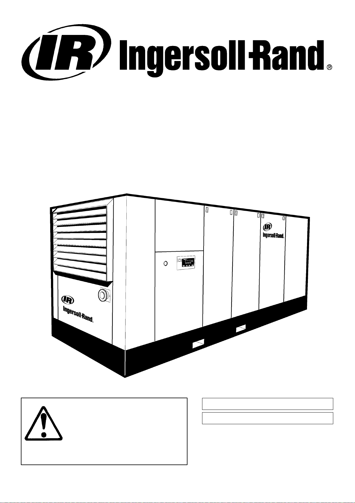
SSR M200–LV
M250–LV
OPERATION AND MAINTENANCE MANUAL
This manual contains
important safety information
and must be made available to
personnel who operate and
maintain this machine.
M200 –>2440110
M250 –>
C.C.N. : 22071393 en
REV. : A
DATE : MAY 2004
SERIAL No :
SERIAL No :
2550255
Page 2
Machine models represented in this manual may be used in various locations world–wide. Machines sold and
shipped into European Union Territories require that the machine display the EC Mark and conform to various
directives. In such cases, the design specification of this machine has been certified as complying with EC directives.
Any modification to any part is absolutely prohibited and would result in the CE Certification and marking being
rendered invalid. A declaration of that conformity follows:
EC DECLARATION OF CONFORMITY WITH EC DIRECTIVES
98/37/EC, 93/68/EEC, 89/336/EEC
WE,
INGERSOLL–RAND COMPANY LIMITED
SWAN LANE
HINDLEY GREEN
WIGAN WN2 4EZ
UNITED KINGDOM
DECLARE THAT, UNDER OUR SOLE RESPONSIBILITY FOR MANUFACTURE AND SUPPLY,
THE PRODUCT(S)
M200–LV M250–LV
TO WHICH THIS DECLARATION RELATES, IS (ARE) IN CONFORMITY WITH THE PROVISIONS
OF THE ABOVE DIRECTIVES USING THE FOLLOWING PRINCIPAL STANDARDS.
EN29001, EN292, EN60204–1, EN1012, EN50081, EN50082
ISSUED AT HINDLEY GREEN ON 01/01/2004 BY H.SEDDON, QUALITY ASSURANCE
MANAGER.
H. SEDDON
EC Pressure Equipment Directive and Related Regulations
We declare that this product has been assessed according to the Pressure Equipment Directive
(97/23/EC) and, in accordance with the terms of this Directive, has been excluded from the scope
of this Directive.
It may carry ”CE” marking in compliance with other applicable EC Directives.
05/04
Page 3

CONTENTS & ABBREVIATIONS
1
CONTENTS
1 CONTENTS
2 FOREWORD
3 ISO SYMBOLS
8 SAFETY
10 GENERAL INFORMATION
20 INSTALLATION / HANDLING
23 OPERATING INSTRUCTIONS
32 AIRCARE WARRANTY
33 MAINTENANCE
36 FAULT FINDING
ABBREVIATIONS & SYMBOLS
#### Contact Ingersoll–Rand for serial number
–>#### Up to Serial No.
####–> From Serial No.
* Not illustrated
{ Option
NR Not required
AR As required
SM Sitemaster/Sitepack
HA High ambient machine
WC Watercooled machine
AC Aircooled machine
ESA European serviced areas
ERS Energy recovery system
T.E.F.C. Totally enclosed fan cooled motor (IP54)
O.D.P. Open drip proof motor (IP23)
ppm parts per million
cs Czech
da Danish
de German
el Greek
en English
es Spanish
et Estonian
fi Finnish
fr French
hu Hungarian
it Italian
lt Lithuanian
lv Latvian, Lettish
mt Maltese
nl Dutch
no Norwegian
pl Polish
pt Portuguese
sk Slovak
sl Slovenian
sv Swedish
zh Chinese
M200–LV M250–LV
Page 4

2
FOREWORD
The contents of this manual are considered to be proprietary and
confidential to Ingersoll–Rand and should not be reproduced without
the prior written permission of Ingersoll–Rand.
Nothing contained in this document is intended to extend any
promise, warranty or representation, expressed or implied, regarding
the Ingersoll–Rand products described herein. Any such warranties or
other terms and conditions of sale of products shall be in accordance
with the standard terms and conditions of sale for such products, which
are available upon request.
This manual contains instructions and technical data to cover all
routine operation and scheduled maintenance tasks by operation and
maintenance staff. Major overhauls are outside the scope of this
manual and should be referred to an authorised Ingersoll–Rand service
department.
The design specification of this machine has been certified as
complying with E.C. directives. Any modification to any part is
absolutely prohibited and would result in the CE certification and
marking being rendered invalid.
All components, accessories, pipes and connectors added to the
compressed air system should be:
. of good quality, procured from a reputable manufacturer and,
wherever possible, be of a type approved by Ingersoll–Rand.
. clearly rated for a pressure at least equal to the machine maximum
allowable working pressure.
. compatible with the compressor lubricant/coolant.
. accompanied with instructions for safe installation, operation and
maintenance.
TABLE 1
Use of the machine to produce compressed air for:
a) direct human consumption
b) indirect human consumption, without suitable filtration and purity
checks.
Use of the machine outside the ambient temperature range
specified i n the GENERAL INFORMATION SECTION of this manual.
Use of the machine where there is any actual or foreseeable risk of
hazardous levels of flammable gases or vapours.
THIS MACHINE IS NOT INTENDED AND MUST NOT BE
USED IN POTENTIALLY EXPLOSIVE ATMOSPHERES,
INCLUDING SITUATIONS WHERE FLAMMABLE GASES OR
VAPOURS MAY BE PRESENT.
Use of the machine fitted with non Ingersoll–Rand approved
components.
Use of the machine with safety or control components missing or
disabled.
The company accepts no responsibility for errors in translation of
this manual from the original English version.
SSR ULTRA COOLANT is a registered trademark of
Ingersoll–Rand Company USA.
INTELLISYS is a registered trademark of Ingersoll–Rand
Company USA.
Details of approved equipment are available from Ingersoll–Rand
Service departments.
The use of repair parts other than those included within the
Ingersoll–Rand approved parts list may create hazardous conditions
over which Ingersoll–Rand has no control. Therefore Ingersoll–Rand
cannot be held responsible for equipment in which non–approved
repair parts are installed.
Ingersoll–Rand reserves the right to make changes and
improvements to products without notice and without incurring any
obligation to make such changes or add such improvements to
products sold previously.
The intended uses of this machine are outlined below and examples
of unapproved usage are also given, however Ingersoll–Rand cannot
anticipate every application or work situation that may arise.
IF IN DOUBT CONSULT SUPERVISION.
This machine has been designed and supplied for use only in the
following specified conditions and applications:
. Compression of normal ambient air containing no known or
detectable additional gases, vapours. or particles
. Operation within the ambient temperature range specified in the
GENERAL INFORMATION section of this manual.
COPYRIGHT 2004
INGERSOLL–RAND COMPANY
No portable communication devices emitting more than 7,5 volts
per metre in the frequency range from 250 MHz to 280 MHz should be
operated within 5 metres of the unit.
The use of the machine in any of the situation types listed in
table 1:–
a) Is not approved by Ingersoll–Rand,
b) May impair the safety of users and other persons, and
c) May prejudice any claims made against Ingersoll–Rand.
M200–LV M250–LV
Page 5
ISO SYMBOLS 3
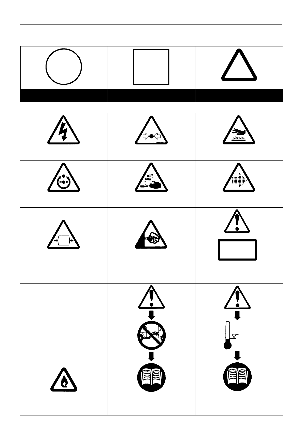
GRAPHIC FORM AND MEANING OF ISO SYMBOLS
Prohibition / Mandatory Information / Instructions Warning
WARNING: Electrical shock risk. WARNING – Pressurised vessel. WARNING – Hot surface.
WARNING – Pressure control. WARNING – Corrosion risk. WARNING – Air/gas flow or Air discharge.
X,XBAR
WARNING – Pressurised component or
system.
WARNING – Hot and harmful exhaust gas.
WARNING – Maintain correct tyre pressure.
(Refer to the GENERAL INFORMATION
section of this manual).
0_C
WARNING – Flammable liquid.
WARNING – Before connecting the tow bar
or commencing to tow consult the
operation and maintenance manual.
WARNING – For operating temperature
below 0_C, consult the operation and
maintenance manual.
M200–LV M250–LV
Page 6
ISO SYMBOLS4
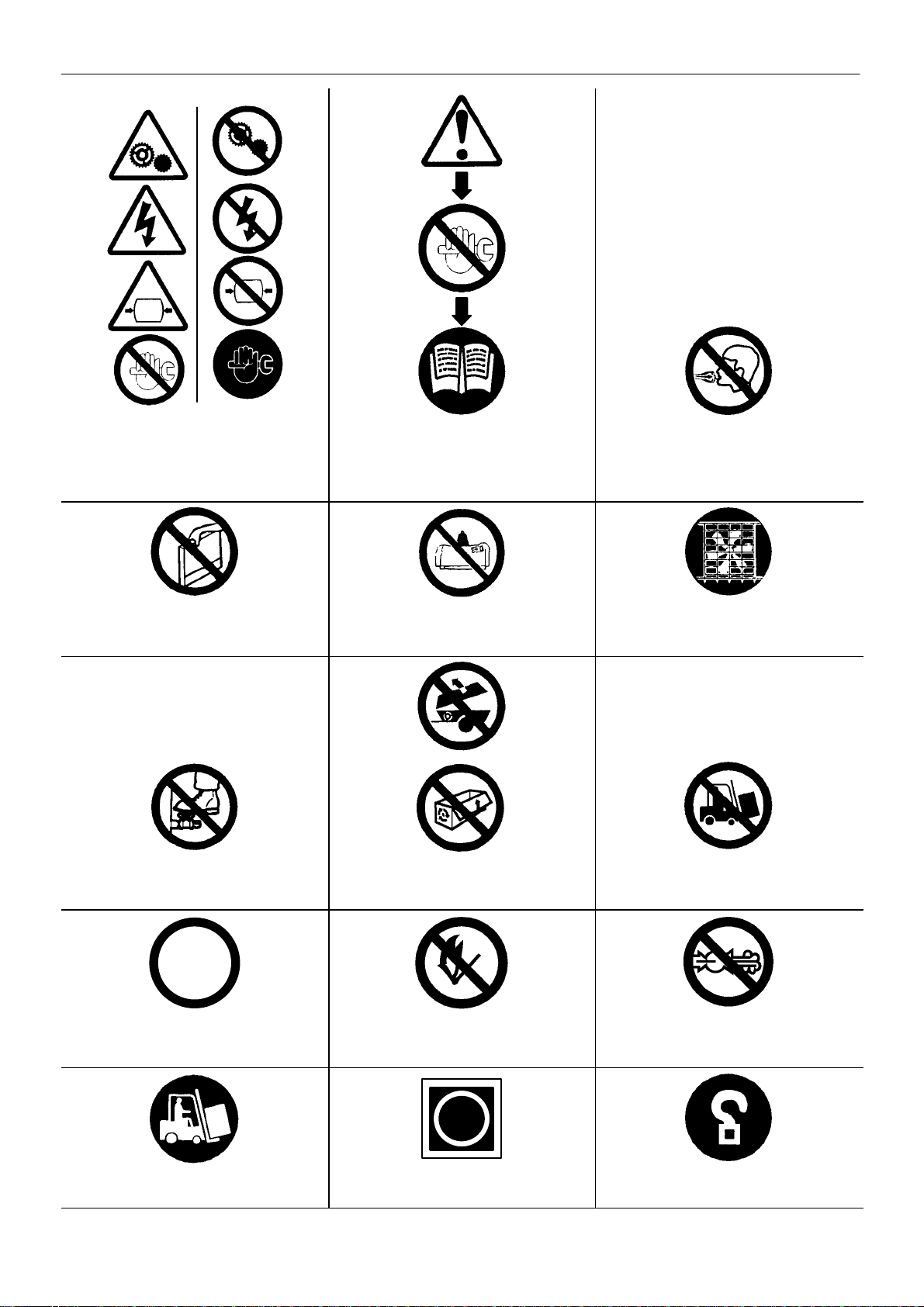
WARNING – Do not undertake any
maintenance on this machine until the
electrical supply is disconnected and the air
pressure is totally relieved.
Do not remove the Operating and Maintenance
manual and manual holder from this machine.
Do not stand on any service valve or other
parts of the pressure system.
WARNING – Consult the operation and
maintenance manual before commencing
any maintenance.
Do not stack.
Do not operate with the doors or enclosure
open.
Do not breathe the compressed air from this
machine.
Do not operate the machine without the guard
being fitted.
Do not use fork lift truck from this side.
XX
km/h
Do not exceed the trailer speed limit. No naked lights.
Use fork lift truck from this side only. Emergency stop. Tie down point
M200–LV M250–LV
Do not open the service valve before the
airhose is attached.
Page 7

ISO SYMBOLS 5
Lifting point. On (power). Off (power).
a
Read the Operation and Maintenance manual
before operation or maintenance of this
machine is undertaken.
SET SEQUENCER STATUS LOAD
SEQUENCER (AUTOMATIC CONTROL) COMPRESSOR OFF LOAD (UNLOADED)
When parking use prop stand, handrake and
wheel chocks.
Contains asbestos.
RESET COMPRESSOR STATUS MODULATE
MALFUNCTION POWER SOILED FILTER
POWER INLET ELECTRIC MOTOR HOURS
M200–LV M250–LV
Page 8
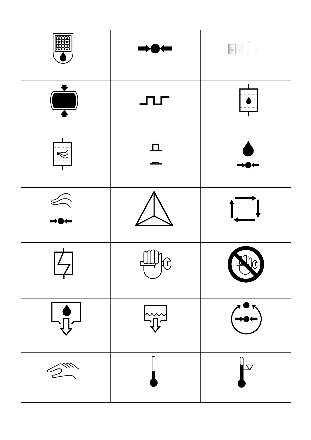
ISO SYMBOLS6
COOLANT SEPARATOR PRESSURE AIR DISCHARGE
PRESSURISED TANK ON / OFF CYCLE COOLANT FILTER
AIR FILTER ON / OFF PUSH BUTTON COOLANT PRESSURE
AIR PRESSURE STAR DELTA IEC 617–7 AUTOMA TIC RESTART
HEAT EXCHANGER MAINTENANCE MAINTENANCE PROHIBITED
COOLANT DRAIN CONDENSATE DRAIN PRESSURE CONTROL
MANUAL (SELECT) TEMPERATURE HIGH TEMPERATURE
M200–LV M250–LV
Page 9
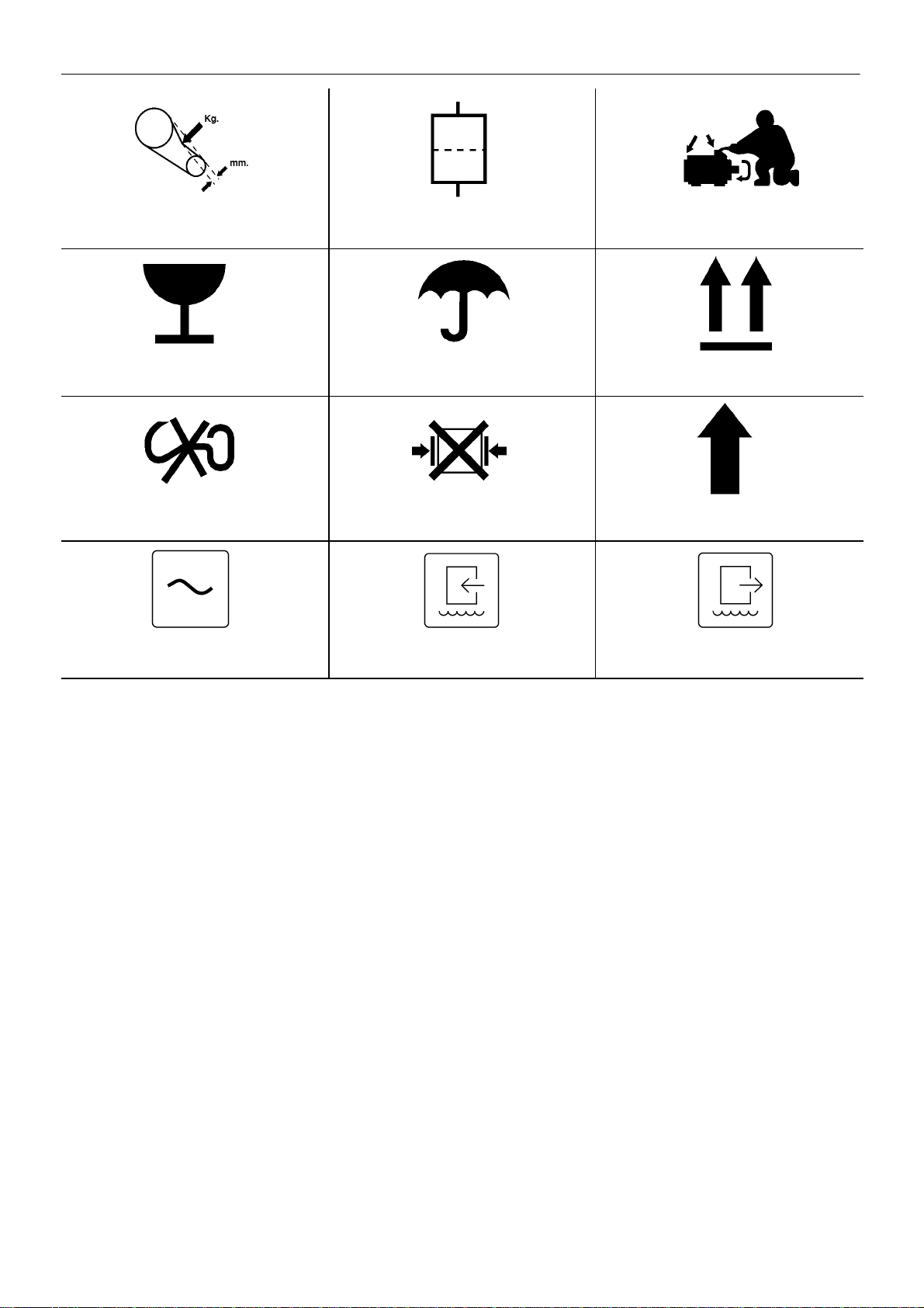
ISO SYMBOLS 7
BELT TENSION FILTER MOTOR LUBRICATION
FRAGILE KEEP DRY THIS WAY UP
USE NO HOOKS NO SIDE CLAMPS ROTATION
POWER INLET (AC) WATER IN WATER OUT
M200–LV M250–LV
Page 10

8
SAFETY
WARNINGS
Warnings call attention to instructions which must be followed
precisely to avoid injury or death.
CAUTIONS
Cautions call attention to instructions which must be followed
precisely to avoid damaging the product, process or its surroundings.
NOTES
Notes are used for supplementary information.
General Information
Ensure that the operator reads and understands the decals and
consults the manuals before maintenance or operation.
Ensure that the Operation and Maintenance manual, and the
manual holder, are not removed permanently from the machine.
Ensure that maintenance personnel are adequately trained,
competent and have read the Maintenance Manuals.
Compressed air and electricity can be dangerous. Before
undertaking any work on the compressor, ensure that the electrical
supply has been isolated and the compressor has been relieved of all
pressure.
WARNING
Imposing a normal or emergency stop on the compressor will
only relieve presure upstream of the minimum pressure valve on
top of the separator tank.
If maintenance work is required downstream of this valve, ensure
that all pressure is relieved at the process vent point external to
the compressor
This state is advised by selecting PACKAGE DISCHARGE
PRESSURE on the control panel.
Make sure that all protective covers are in place and that the
canopy/doors are closed during operation.
Installation of this compressor must be in accordance with
recognised electrical codes and any local Health and Safety Codes.
The use of plastic bowls on line filters without metal guards can be
hazardous. Their safety can be af fected by either synthetic lubricants,
or the additives used in mineral oils. Metal bowls should be used on a
pressurised system.
Compressed air can be dangerous if incorrectly handled. Before
doing any work on the unit, ensure that all pressure is vented from the
system and that the machine cannot be started accidentally .
Compressed air
Ensure that the machine is operating at the rated pressure and that
the rated pressure is known to all relevant personnel.
All air pressure equipment installed in or connected to the machine
must have safe working pressure ratings of at least the machine rated
pressure.
The discharged air contains a very small percentage of compressor
lubricating oil and care should be taken to ensure that downstream
equipment is compatible.
If the discharged air is to be ultimately released into a confined
space, adequate ventilation must be provided.
When using compressed air always use appropriate personal
protective equipment.
All pressure containing parts, especially flexible hoses and their
couplings, must be regularly inspected, be free from defects and be
replaced according to the Manual instructions.
Compressed air can be dangerous if incorrectly handled. Before
doing any work on the unit, ensure that all pressure is vented from the
system and that the machine cannot be started accidentally .
Avoid bodily contact with compressed air .
The safety valve located in the separator tank must be checked
periodically for correct operation.
Materials
The following substances are used in the manufacture of this
machine and may be hazardous to health if used incorrectly:
. preservative grease
. rust preventative
. compressor coolant
AVOID INGESTION, SKIN CONTACT AND INHALATION OF
FUMES
For further information, consult Material Data Sheets ACGP 011/96
(ULTRA COOLANT) and IRACA145 (food grade coolant).
Should compressor lubricant come into contact with the eyes, then
irrigate with water for at least 5 minutes.
Should compressor lubricant come into contact with the skin, then
wash off immediately .
Consult a physician if large amounts of compressor lubricant are
ingested.
Consult a physician if compressor lubricant is inhaled.
Never give fluids or induce vomiting if the patient is unconscious or
having convulsions.
Transport
When loading or transporting machines ensure that the specified
lifting and tie down points are used.
When refitting any enclosure panels or doors, it is essential to
ensure that no persons or equipment remain inside the compressor.
If more than one compressor is connected to one common
downstream plant, effective check valves and isolation valves must be
fitted and controlled by work procedures, so that one machine cannot
accidentally be pressurised / over pressurised by another.
Compressed air must not be used for a direct feed to any form of
breathing apparatus or mask.
M200–LV M250–LV
Page 11

SAFETY
9
Electrical
Keep all parts of the body and any hand–held tools or other
conductive objects, away from exposed live parts of the compressor
electrical system. Maintain dry footing, stand on insulating surfaces
and do not contact any other portion of the compressor when making
adjustments or repairs to exposed live parts of the compressor
electrical system.
Close and lock all access doors when the compressor is left
unattended.
Do not use extinguishers intended for Class A or Class B fires on
electrical fires. Use only extinguishers suitable for class BC or class
ABC fires.
Attempt repairs only in clean, dry, well lighted and ventilated areas.
When refitting any enclosure panels or doors, it is essential to
ensure that no persons or equipment remain inside the compressor.
Connect the compressor only to electrical systems that are
compatible with its electrical characteristics and that are within it’s rated
capacity.
Condensate disposal
Condensate cannot be discharged into fresh/surface water drains.
In some regions compressor condensate containing ULTRA
COOLANT can be fed directly into a drainage system that has
downstream sewerage treatment.
As waste water regulations vary by country and region it is the
responsibility of the user to establish the limitations and regulations in
their particular area. Ingersoll–Rand and its associated distributors are
happy to advise and assist in these matters.
Coolant disposal
Steps to be taken in the case of spillage: Soak up with a suitable
absorbent material, then sweep into a plastic bag for disposal.
Burn in an approved incinerator, or according to local area or
country regulations.
For further information, consult Material Data Sheets ACGP 011/96
(ULTRA COOLANT) and IRACA145 (food grade coolant).
The above information contains data supplied in support of United
Kingdom Control of Substances Hazardous to Health (C.O.S.H.H.)
regulations.
M200–LV M250–LV
Page 12
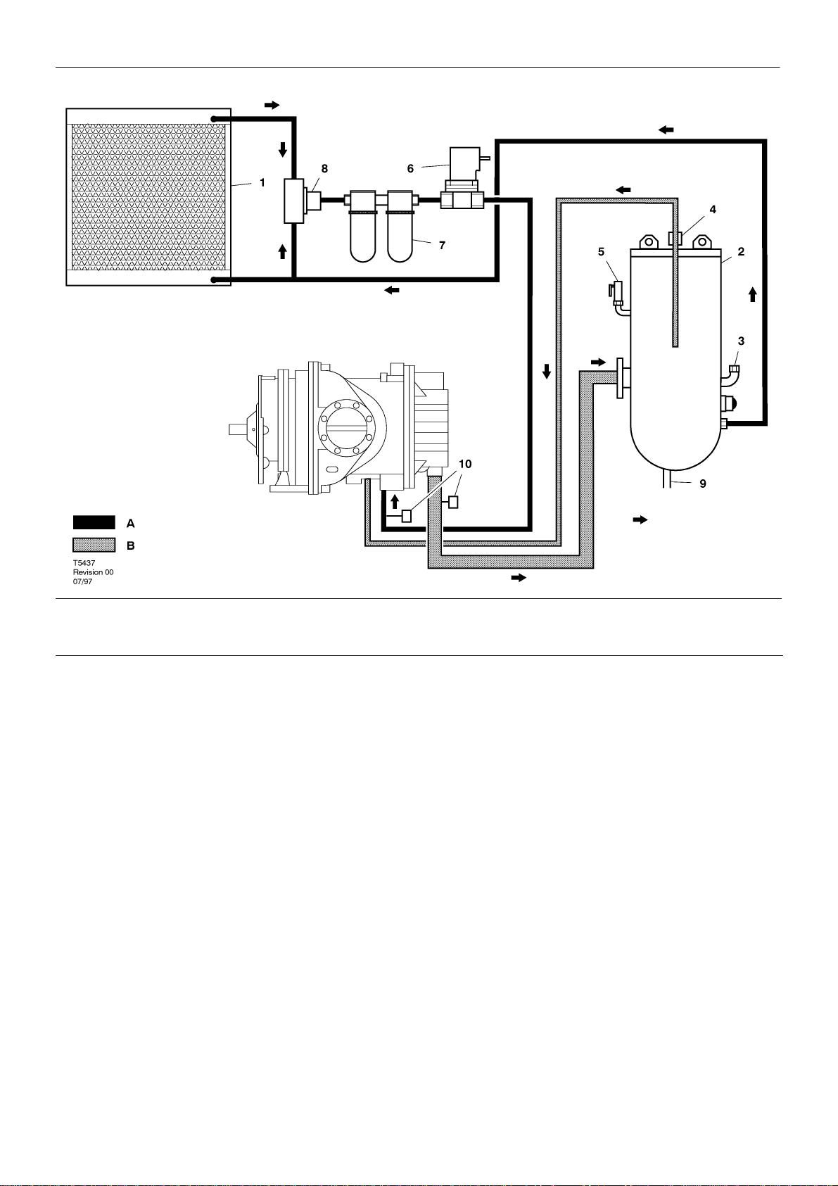
10
GENERAL INFORMATION
AC
LUBRICA TION SYSTEM: AIR COOLED MACHINES
KEY
A. LUBRICANT
B. LUBRICANT / AIR
1. COOLER
2. SEPARATOR TANK
3. FILLER PLUG
4. ORIFICE & SCREEN
5. SAFETY VALVES
6. COOLANT STOP VALVE (5SV)
7. COOLANT FILTER
8. THERMOSTATIC VALVE
9. TO DRAIN VALVE
10.THERMISTOR
M200–LV M250–LV
Page 13
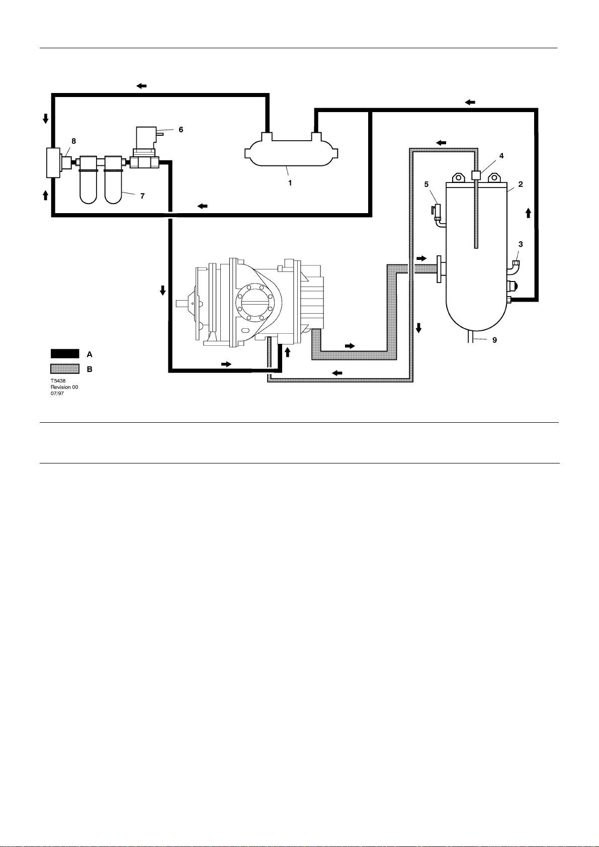
GENERAL INFORMATION
11
WC
LUBRICA TION SYSTEM: WATER COOLED MACHINES
KEY
A. LUBRICANT
B. LUBRICANT / AIR
1. COOLER
2. SEPARATOR TANK
3. FILLER PLUG
4. ORIFICE & SCREEN
5. SAFETY VALVES
6. COOLANT STOP VALVE (5SV)
7. COOLANT FILTER
8. THERMOSTATIC VALVE
9. TO DRAIN VALVE
M200–LV M250–LV
Page 14
12
GENERAL INFORMATION
AC
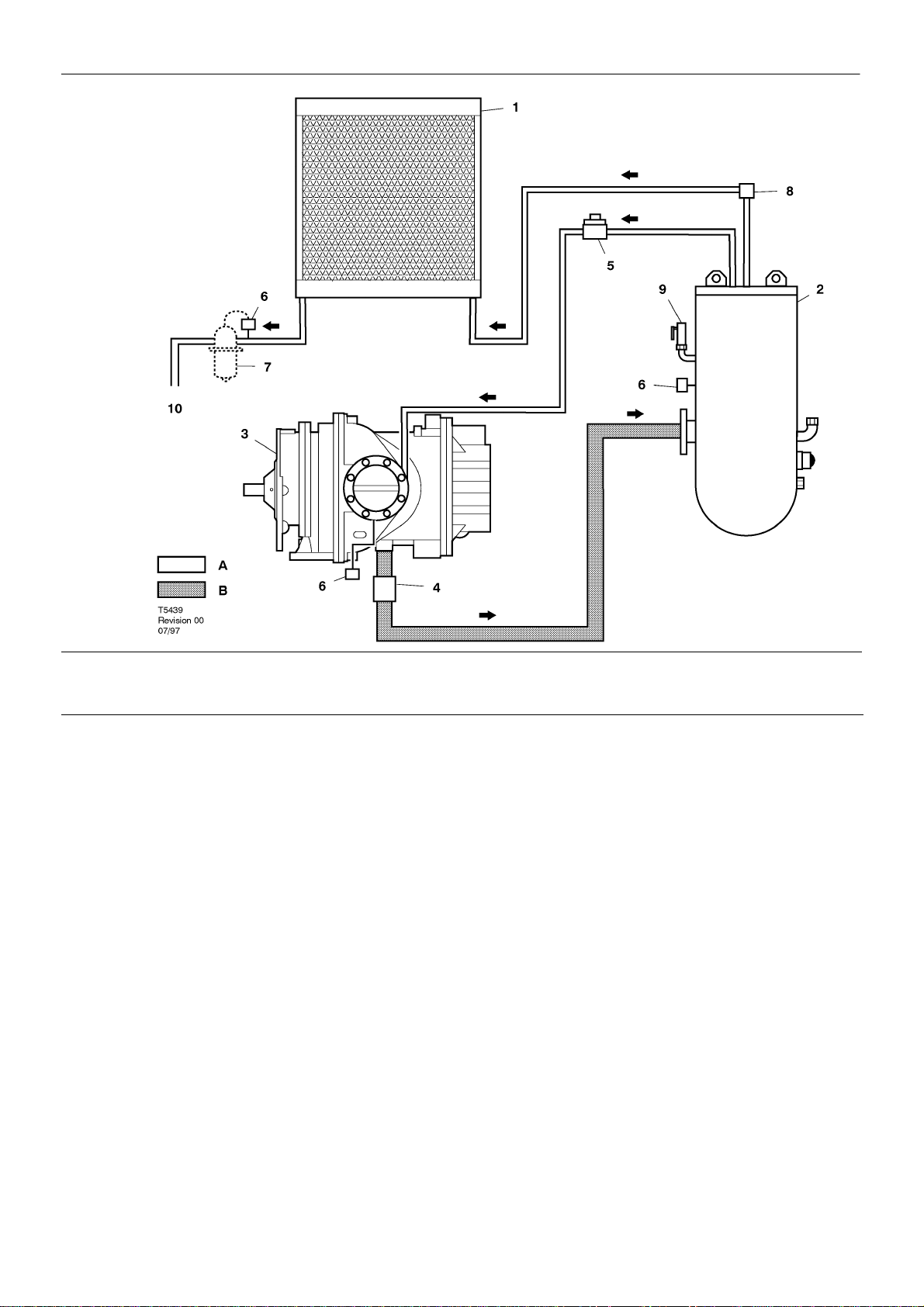
DISCHARGE AIR PIPING: AIR COOLED MACHINES
KEY
A AIR
B. LUBRICANT / AIR
1. AFTERCOOLER
2. SEPARATOR TANK
3. COMPRESSOR
4. CHECK VALVE
5. BLOWDOWN VALVE (3SV)
6. PRESSURE TRANSDUCER
7. MOISTURE SEPARATOR (OPTION)
8. MINIMUM PRESSURE VALVE
9. SAFETY VALVE
10.TO AIR DISCHARGE SOCKET
M200–LV M250–LV
Page 15
GENERAL INFORMATION
13
WC
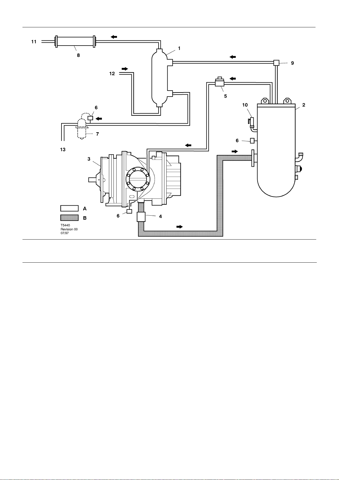
AIR PIPING & WATER PIPING: WATER COOLED MACHINES
KEY
A AIR
B. LUBRICANT / AIR
1. AFTERCOOLER
2. SEPARATOR TANK
3. COMPRESSOR
4. CHECK VALVE
5. BLOWDOWN VALVE (3SV)
6. PRESSURE TRANSDUCER
7. MOISTURE SEPARATOR (OPTION)
8. COOLER
9. MINIMUM PRESSURE VALVE
10.SAFETY VALVE
11.TO WATER DISCHARGE SOCKET
12.FROM WATER INLET SOCKET
13.TO AIR DISCHARGE SOCKET
M200–LV M250–LV
Page 16
14
GENERAL INFORMATION
GENERAL OPERATION
The compressor is an electric motor driven, single stage screw
compressor, complete with accessories piped, wired and baseplate
mounted. It is a totally self contained air compressor package.
The standard compressor is designed to operate in an ambient
range o f 1 , 7 _C to 46_C. The standard maximum temperature of 46_C
is applicable up to an elevation of 1000m (3280ft) above sea level.
Above this altitude significant reductions in ambient temperature are
required if a standard motor is to be used.
Compression in the screw type air compressor is created by the
meshing o f two (male & female) helical rotors.
The air/coolant mixture discharges from the compressor into the
separation system. This system removes all but a few PPM of the
coolant from the discharge air. The coolant is returned to the cooling
system and the air passes to the aftercooler and out of the compressor
through the moisture separator (optional).
Air is pulled into the compressor by the cooling fan and is pushed
through the coolers.
By cooling the discharge air and passing it through the separator,
much of the water vapour which is naturally present in the air, can be
removed.
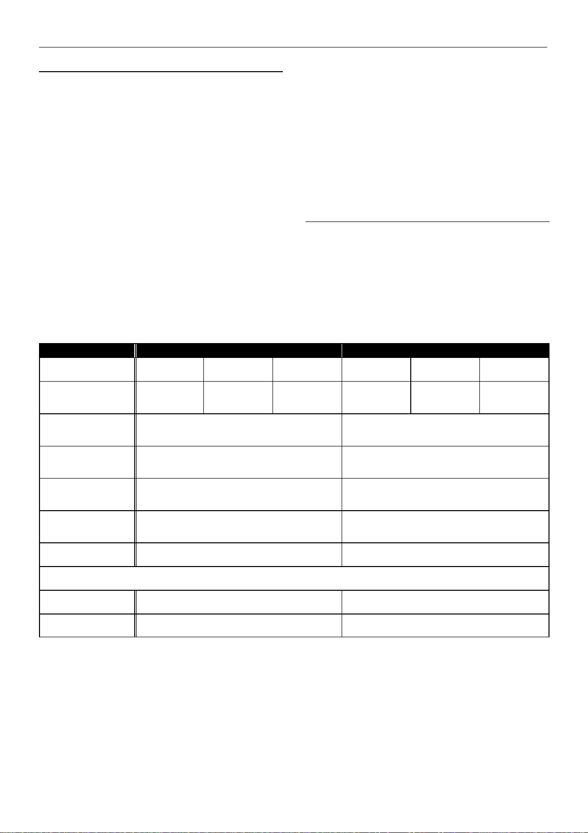
M200AC M200WC
PRESSURE 7.5 bar
(L)
CAPACITY 34.3 m3/min
8.5 bar
(M)
32.9 m3/min
The coolant system consists of a sump, cooler, thermostatic valve
and a filter. When the unit is operating, the coolant is pressurised and
forced to the compressor bearings.
The compressor load control system is automatic ’On–Off line’. The
compressor will operate to maintain a set discharge line pressure and
is provided with an auto restart system for use in plants where the air
demand varies widely.
Panel instrumentation is provided to indicate the compressor
operating conditions and general status.
The modulation system extends the control types to Modulation
(capacity control) and Automatic Control System when the compressor
switches between ’On–Of f line’ and modulation as demand varies.
The electrical components are housed in a readily accessible sheet
metal cabinet.
Safety of operation is provided for as the compressor will shut down
if excessive temperatures, electrical overload conditions, or system
over pressure should occur.
10.0 bar
(H)
30.2 m3/min
7.5 bar
(L)
34.3 m3/min
8.5 bar
(M)
32.9 m3/min
10.0 bar
(H)
30.2 m3/min
1211 ft3/min.
FULL LOAD CURRENT
(MAXIMUM)
380V
FULL LOAD CURRENT
(MAXIMUM)
415V
STARTING CURRENT
(MAXIMUM)
380V
STARTING CURRENT
(MAXIMUM)
415V
*NOISE LEVEL
CAGI PNEUROP 1m
* Equivalent continuous sound pressure level (workstation) (rated load)
WEIGHT
O.D.P.
WEIGHT
T.E.F.C.
1162 ft3/min.
465 433
431 407
862 862
942 942
84 +/– 3dB(A) 84 +/– 3dB(A)
3930 kg 4030 kg
4560 kg 4660 kg
1066 ft3/min.
1211 ft3/min.
1162 ft3/min.
1066 ft3/min.
M200–LV M250–LV
Page 17
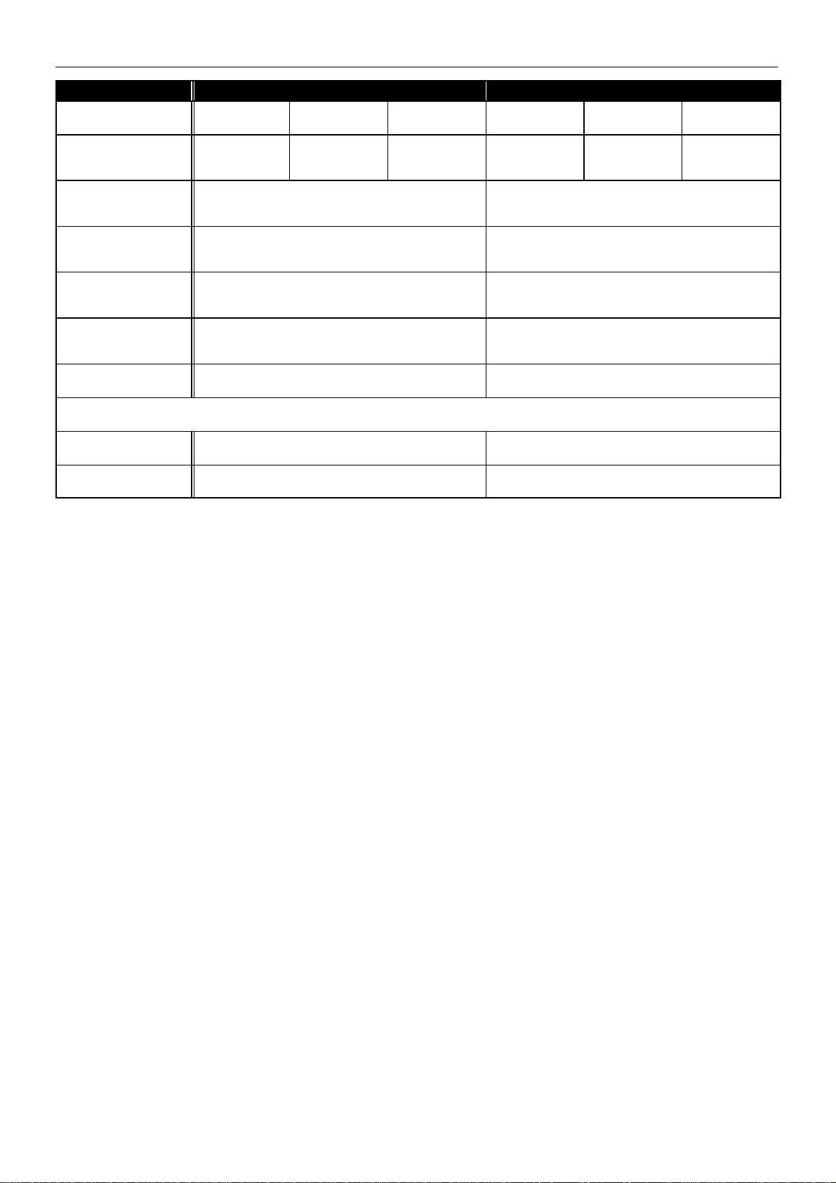
PRESSURE 7,5 bar
(L)
CAPACITY 43,9 m3/min
GENERAL INFORMATION
M250AC M250WC
8,5 bar
(M)
42,5 m3/min
10 bar
(H)
38,8 m3/min
7,5 bar
(L)
43,9 m3/min
8,5 bar
(M)
42,5 m3/min
15
10 bar
(H)
38,8 m3/min
1550 ft3/min.
FULL LOAD CURRENT
(MAXIMUM)
380V
FULL LOAD CURRENT
(MAXIMUM)
415V
STARTING CURRENT
(MAXIMUM)
380V
STARTING CURRENT
(MAXIMUM)
415V
*NOISE LEVEL
CAGI PNEUROP 1m
* Equivalent continuous sound pressure level (workstation) (rated load)
WEIGHT
O.D.P.
WEIGHT
T.E.F.C.
1501 ft3/min.
557 538
536 519
1020 1020
1115 1115
84 +/– 3dB(A) 84 +/– 3dB(A)
4680 kg 4780 kg
5284 kg 5384 kg
1370 ft3/min.
1550 ft3/min.
1501 ft3/min.
1370 ft3/min.
M200–LV M250–LV
Page 18
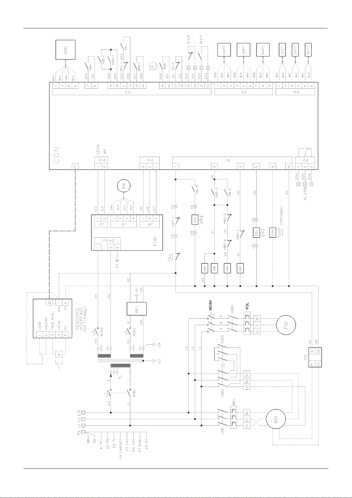
16
GENERAL INFORMATION
AC
22158653
Revision A
M200–LV M250–LV
Page 19

KEY
GENERAL INFORMATION
17
PE Earth lead, Main terminal
MM Earth lead, motor
SB Earth lead, sub–base
E1 Earth lead, RFI filter
E2 Earth lead, Fan motor
E3 Earth lead, Control transformers
E4 Earth lead, Instrument panel
E5 Earth lead, 5SV
E6 Earth lead, 3SV
E7 Earth lead, PCB1
E8 Earth lead, 0V
FOL Fan motor, Relay, overload
L1 – L3 Mains terminals
MCB1 Miniature circuit breaker, transformer T1 supply
MCB2 Miniature circuit breaker, 110V control circuits
MCB3 Miniature circuit breaker, 24V control circuits
MCB4 Miniature circuit breaker, fan motor
KM1 Main contactor
KM2 Delta contactor
KM3 Star contactor
KM4 Fan contactor
MM Main motor
FM Fan motor
TR Thermistor relay, motor windings
MOL Main motor overload relay
RFI RFI filter
PCB1 Printed circuit board, Power supply unit
HAT–1Switch, high air temperature (discharge air)
ES Emergency stop
SMC Stepper motor controller
SM Stepper motor
5SV Coolant stop valve
3SV Blowdown valve
CON Intellisys controller
3DP Pressure switch (Fouled coolant filter)
3APT Pressure transducer, separator pressure
1AVPTPressure transducer, inlet vacuum
4APT Pressure transducer, package discharge pressure
2ATT Temperature sensor, airend discharge
4ATT Temperature sensor, package discharge
2CTT Temperature sensor, injected coolant
CFO Common fault output
RSP Remote stop
RST Remote start
M200–LV M250–LV
Page 20
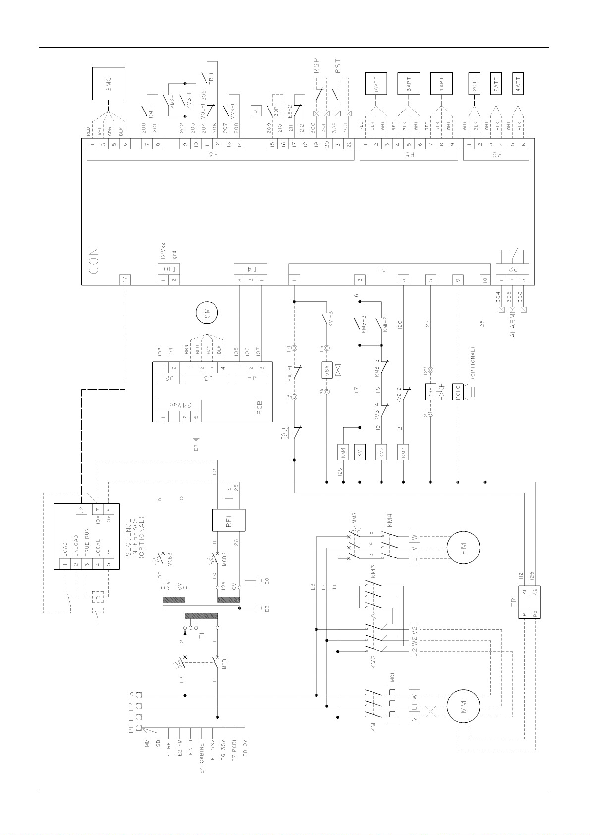
18
GENERAL INFORMATION
WC
22065734
Revision A
M200–LV M250–LV
Page 21

KEY
GENERAL INFORMATION
19
PE Earth lead, Main terminal
MM Earth lead, motor
SB Earth lead, sub–base
E1 Earth lead, RFI filter
E2 Earth lead, Fan motor
E3 Earth lead, Control transformers
E4 Earth lead, Instrument panel
E5 Earth lead, 5SV
E6 Earth lead, 3SV
E7 Earth lead, PCB1
E8 Earth lead, 0V
L1 – L3 Mains terminals
MCB1 Miniature circuit breaker, transformer T1 supply
MCB2 Miniature circuit breaker, 110V control circuits
MCB3 Miniature circuit breaker, 24V control circuits
MMS Miniature circuit breaker, fan motor
KM1 Main contactor
KM2 Delta contactor
KM3 Star contactor
KM4 Fan contactor
MM Main motor
FM Fan motor
TR Thermistor relay, motor windings
MOL Main motor overload relay
RFI RFI filter
PCB1 Printed circuit board, Power supply unit
HAT–1Switch, high air temperature (discharge air)
ES Emergency stop
SMC Stepper motor controller
SM Stepper motor
5SV Coolant stop valve
3SV Blowdown valve
CON Intellisys controller
3DP Pressure switch (Fouled coolant filter)
3APT Pressure transducer, separator pressure
1AVPTPressure transducer, inlet vacuum
4APT Pressure transducer, package discharge pressure
2ATT Temperature sensor, airend discharge
4ATT Temperature sensor, package discharge
2CTT Temperature sensor, injected coolant
CFO Common fault output
RSP Remote stop
RST Remote start
M200–LV M250–LV
Page 22
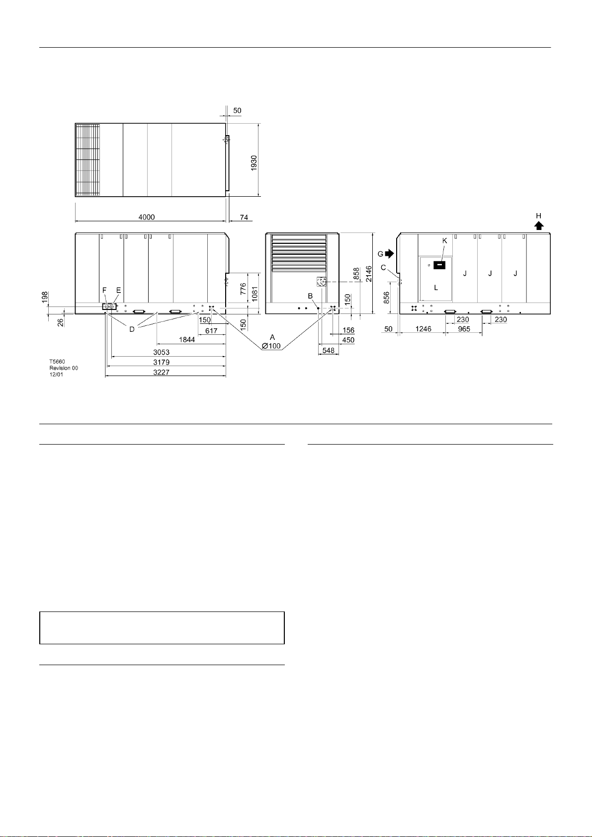
20
INSTALLATION / HANDLING
KEY
A Electrical cable entry
B1/2” BSPP Condensate drain
C 3” ASA Flange – Air discharge
D1/4” BSPP Coolant drain
E, F 2” BSPP Water in/out (WC)
G Cooling air intake
H Cooling air exhaust
J Access panels
K Control panel
L Control cabinet door
NOTE
All dimensions are in millimetres unless otherwise stated.
UNPACKING
The compressor will normally be delivered with a polythene cover.
If a knife has to be used to remove this cover ensure that the exterior
paintwork of the compressor is not damaged.
Incorporated within the base of the compressor are slots to enable
a fork lift truck (5 ton minimum) to move the machine. Alternatively a
special lifting frame can be supplied to enable a crane or hoist to move
the compressor.
LOCATION IN THE PLANT
The compressor can be installed on any level floor capable of
supporting it. A dry, well ventilated area where the atmosphere is as
clean as possible is recommended.
Sufficient space all round and above the compressor must be
allowed, t o enable the ef fective removal of the cooling air which, in turn,
will reduce the risk of re–circulating the cooling air back through the
compressor.
CAUTION: A minimum of 1 metre all round the compressor is
recommended. If headroom is restricted, then the exhaust should be
ducted or deflected away from the machine.
M200–LV M250–LV
Page 23
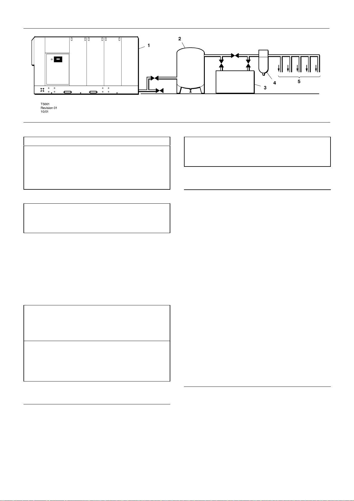
INSTALLATION / HANDLING
21
KEY
1. Compressor
2. Air Receiver
3. Air Dryer
4. Compressed air filters
5. System demand points
NOTE
Items [2] to [5] are optional or may be existing items of plant. Refer
to your Ingersoll–Rand distributor / representative for specific
recommendations.
Hard surfaces may reflect noise with an apparent increase in the
decibel level. When sound transmission is important, a sheet of rubber
or cork can be installed beneath the machine to reduce noise.
It is recommended that provision be made for lifting heavy
components during major overhaul.
CAUTION
Screw type compressors [1] should not be installed in air systems
with reciprocating compressors without means of isolation such as a
common receiver tank. It is recommended that both types of
compressor be piped to a common receiver using individual air lines.
NOTE
After the machine has been sited, remove the four transportation
bolts and spacers which are marked with fluorescent tags. Two are
situated o n the airend support and the other two on the motor support.
ELECTRICAL DATA
An independent electrical isolator should be installed adjacent to the
compressor.
Feeder cables should be sized by the customer/electrical
contractor to ensure that the circuit is balanced and not overloaded by
other electrical equipment. The length of wiring from a suitable
electrical feed point is critical as voltage drops may impair the
performance of the compressor.
The applied voltage must be compatible with the motor and
compressor data plate ratings.
The control circuit transformer has different voltage tappings.
Ensure that these are set for the specific applied voltage prior to
starting.
Feeder cable connections to studs L1–L2–L3 on isolator should be
tight and clean.
CAUTION
Never test the insulation resistance of any part of the machines
electrical circuits, including the motor without completely disconnecting
the intellisys controller.
CAUTION
The use of plastic bowls on line filters and other plastic air line
components without metal guards can be hazardous. Their safety can
be affected by either synthetic coolants or the additives used in mineral
oils. From a safety standpoint, metal bowls should be used on any
pressurised system.
DISCHARGE PIPING
Discharge piping should be at least as large as the discharge
connection o f the compressor. All piping and fittings should be suitably
rated for the discharge pressure.
It is essential when installing a new compressor [1], to review the
total air system. This is to ensure a safe and effective total system. One
item which should be considered is liquid carryover. Installation of air
dryers [3] is always good practice since properly selected and installed
they can reduce any liquid carryover to zero.
It is good practice to locate an isolation valve close to the
compressor and to install line filters [4].
NOTICE
Fuses F1 and F2 are supplied loose in the starter cabinet. Do not
install until all electrical testing has been completed.
WATER COOLED UNITS
Cooling Water Piping
Water piping to and from the compressor package must be 2”diameter
or larger. Isolation valves with side drains should be installed on both
the inlet and outlet lines. Also a strainer of 3mm–mesh size should be
installed on the inlet line. Strainers are available from Ingersoll–Rand.
Ingersoll–Rand CPN 54690060.
It is recommended that a normally closed solenoid valve be fitted to the
water outlet side of the compressor package. This is to be wired into the
compressor control circuit. This option detail is available from
Ingersoll–Rand.
Carefully inspect your water system before installing the compressor
package. Ensure that the piping is free of scale and deposits that may
restrict water flow to the compressor package.
Proper operation of your compressor requires that the water flow listed
below be provided at a maximum supply temperature of 32_C
M200–LV M250–LV
Page 24
22
INSTALLATION / HANDLING
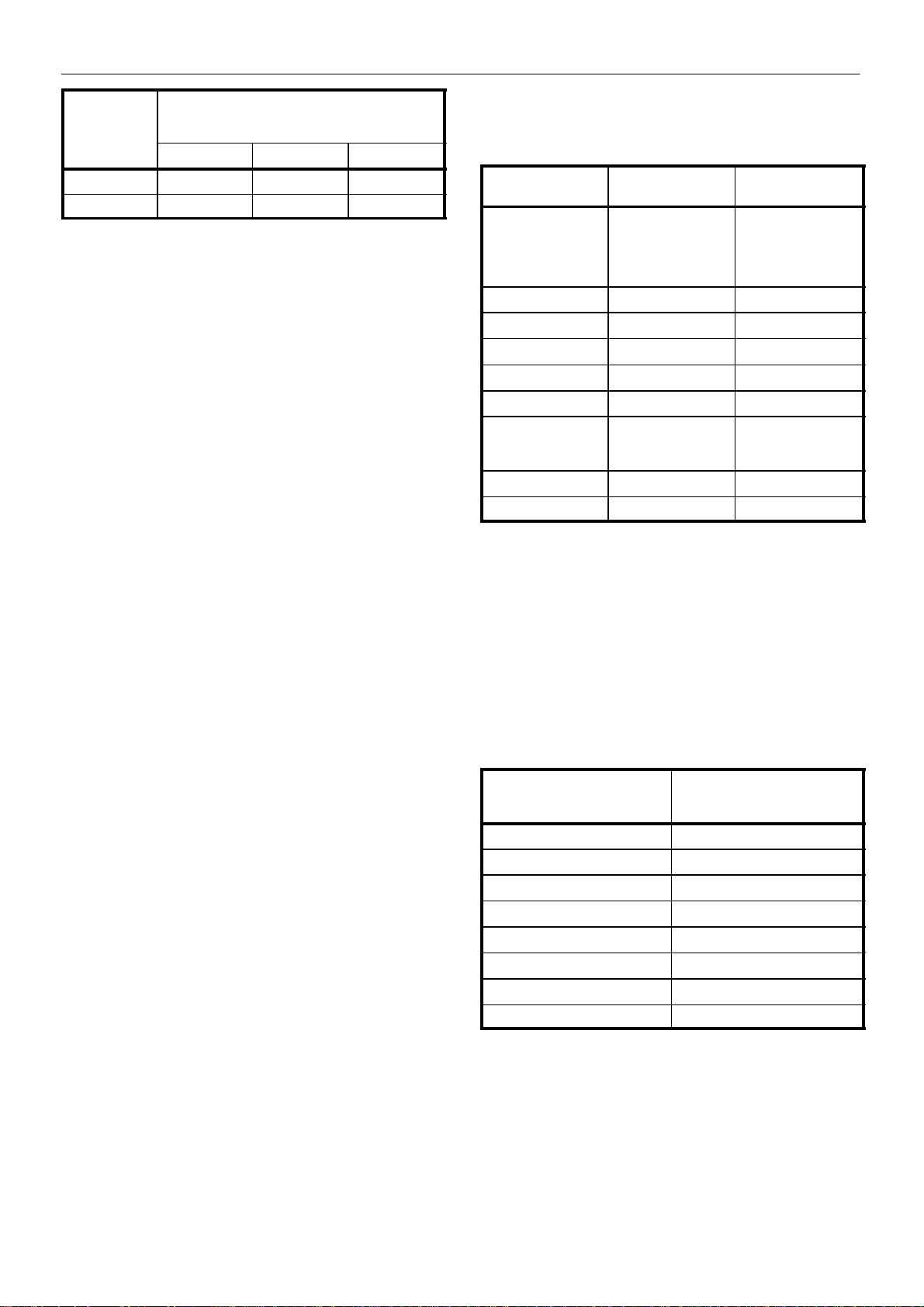
Minimum cooling water requirement at ambient
temperatures, in litres per minute (UK gallons per
Model Range
M200 91(20) 110(24) 180(40)
M250 114(25) 158(35) 246(54)
Water temperature and pressure gauges should be installed in the
water piping for use in any fault finding of the water system. Water
pressure should ideally be between 3 and 5 bar.
Water cleanliness is also extremely important. Cleaning of coolers as
a result of fouling is a customer responsibility. Therefore, it is highly
recommended that proper water quality must meet the requirements
listed i n WATER QUALITY RECOMMENDATIONS later in this section.
Venting the water system
At the initial installation or for start–up after draining the water system
proceed to vent the system as follows
1 Locate the water system vent cocks on top of the aftercooler and
lubricant cooler.
2 Open the water valve(s) allowing water to flow to the package.
3 Open the vent cocks and allow all air to escape from the system.
When water is observed at the vent cocks, close them
The system is now vented.
minute)
50_F / 10_C 70_F / 21_C 90_F / 32_C
Cooling Water Analyses Chart
Substances
Corrosivity (Hardness, pH, Total Dissolved Solids, Temperature a t inlet Alkalinity)
Iron Monthly <2 ppm
Sulphate Monthly <50 ppm
Chloride Monthly <50 ppm
Nitrate Monthly <2 ppm
Silica Monthly < 100 ppm
Desolated Oxygen Daily — if
Oil & Grease Monthly <5 ppm
Ammonia Monthly <1 ppm
Test interval Acceptable
Monthly — if stable
for 3 to 4 months,
analyse quarterly.
stable,analyse
weekly
concentration
Langelier Index 0 to 1
0 ppm (as low
aspossible)
Draining the water system
Should it become necessary to completely drain the water system,
proceed as follows.
1 Disconnect the inlet and discharge water lines from the connections
located a t the rear of the unit.
2 Locate the aftercooler and lubricant cooler. Remove the drain plugs
located at the bottom of the coolers. Allow the system to completely
drain.
Water quality recommendations
Water quality is often overlooked when the cooling system of a
water–cooled air compressor is examined. Water quality determines
how effective the heat transfer rate, as well as the flow rate will remain
during the operation life of the unit. It should be noted that the quality
of water used in any cooling system does not remain constant during
the operation of the system. Evaporation, corrosion, chemical and
temperature changes, aeration, scale and biological formations effect
the water makeup. Most problems in a cooling system show up first in
a reduction in the heat transfer rate, then in a reduced flow rate and
finally with damage to the system.
Scale: Scale formation inhibits effective heat transfer, yet it does help
prevent corrosion. Therefore, a thin uniform coating of calcium
carbonate is desired on the inner surface. Perhaps the largest
contributor to scale formation is the precipitation of calcium carbonate
out of the water. This is dependent on temperature and pH. The higher
the pH value, the greater the chance of scale formation. Scale can be
controlled with water treatment.
Corrosion: In contrast to scale formation is the problem of corrosion.
Chlorides cause problems because of their size and conductivity. Low
pH levels promote corrosion, as well as high levels of dissolved
oxygen.
Fouling: Biological and organic substances (slime) can also cause
problems, but in elevated temperature environments such as cooling
processes they are not a major concern. If they create problems with
clogging, commercial shock treatment are available.
To ensure good operation life and performance of the compressor
cooling system, the recommended acceptable ranges for different
water constituents are included below:
The Ingersoll–Rand Hydro–check cooling water analysis kit
CPN89223481 provides a sample bottle and pre–addressed return
tube to our laboratory, where a full report on water quality will be issued.
SEA WATER COOLED UNITS
Sea Water Pressure in Bars Orifice diameter in mm to give a
maximum sea water flow of
340l/min
3 bar 23
4 bar 21
5 bar 20
6 bar 19
7 bar 18
8 bar 17
9 bar 17
10 bar 16
Water cleanliness is also extremely important. Strainers are available
from Ingersoll–Rand. Cleaning of coolers as a result of fouling is a
customer responsibility.
Isolation valves with side drains should be installed on both the inlet and
outlet lines.
It is recommended that a normally closed solenoid valve be fitted to the
water outlet side of the compressor package.
M200–LV M250–LV
Page 25
OPERATING INSTRUCTIONS
23
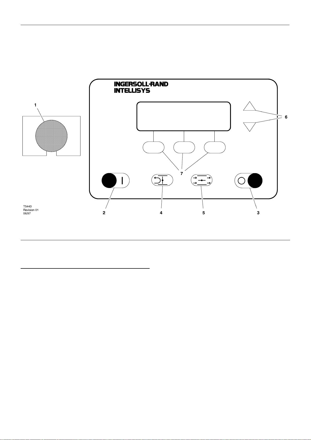
INTELLISYS CONTROLS
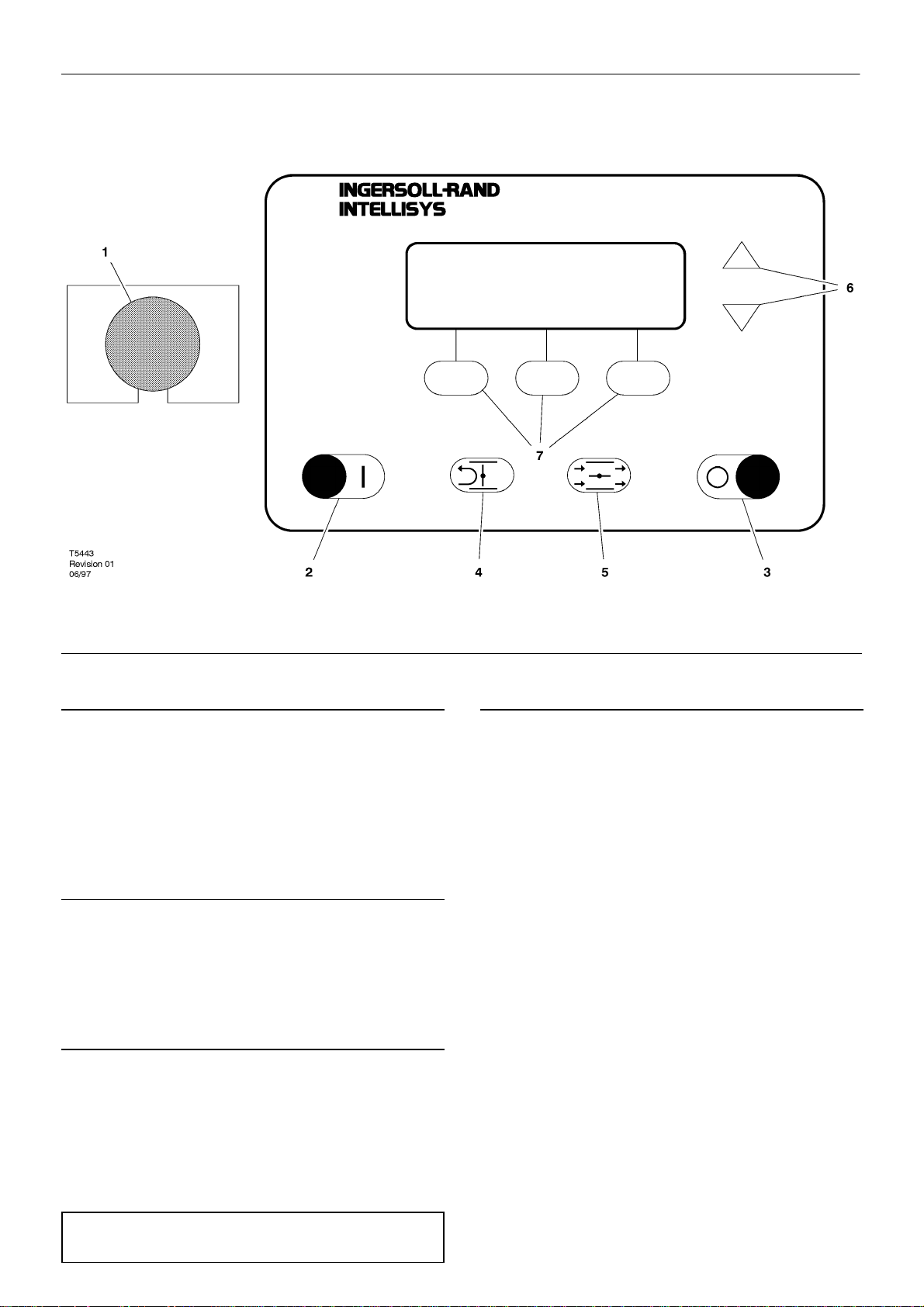
1. EMERGENCY STOP
Pressing this switch stops the compressor immediately. The
compressor can not be restarted until the switch is manually reset. Turn
the switch knob clockwise to reset.
The controller display will illuminate, indicating that the line and
control voltages are available.
2. START
Pressing this button will start the compressor if the display shows
READY TO START. the compressor will start and load if there is
sufficient demand for air.
3. STOP
Pressing this button will activate the unloaded stop sequence. If the
compressor is running loaded, it will unload and continue to run
unloaded for an adjustable 10 to 30 seconds and then stop. If the
compressor is running unloaded, it will stop immediately.
4. UNLOAD
Pressing this button will cause the compressor to unload and
remain unloaded. The display will indicate that the machine is
RUNNING UNLOADED and MODE:UNLOAD.
5. LOAD
Pressing this button will cause the compressor to load if the
compressor is running and if the DISCHARGE PRESSURE is less
than the ONLINE PRESSURE. This also returns the machine to the
operating mode that is specified by the MODE OF OPERATION set
point.
The other five buttons provide access to various
operator–selectable functions and machine operating conditions. The
purpose of each of these buttons is defined by the display screen and
the particular function being performed at that time.
6. ARROWS
These up and down buttons have multiple functions relating to the
right half of the display screen. When lists are presented, the buttons
are used to move up or down through the items on the list. The small
arrow(s) displayed in the upper right hand corner of the display screen
indicate when you can move up (designated by arrow head pointing up)
and/or down (designated by arrow head pointing down) through the list.
When the value of a specific machine operating parameter is
highlighted on the display screen for the purpose of changing that
value, the buttons are used to change the value itself.
7. DISPLA Y BUTTONS
The functions of the three buttons below the display screen change
and are defined by the words immediately above them in the bottom line
of the screen. Each function, such as MAIN MENU, STATUS, etc., is
described in appropriate sections in this manual.
M200–LV M250–LV
Page 26
24
OPERATING INSTRUCTIONS
barg
7,5
RUNNING LOADED AIREND DISCHARGE TEMP
MODE: MOD/ACS 89_C
DISPLAY SCREEN
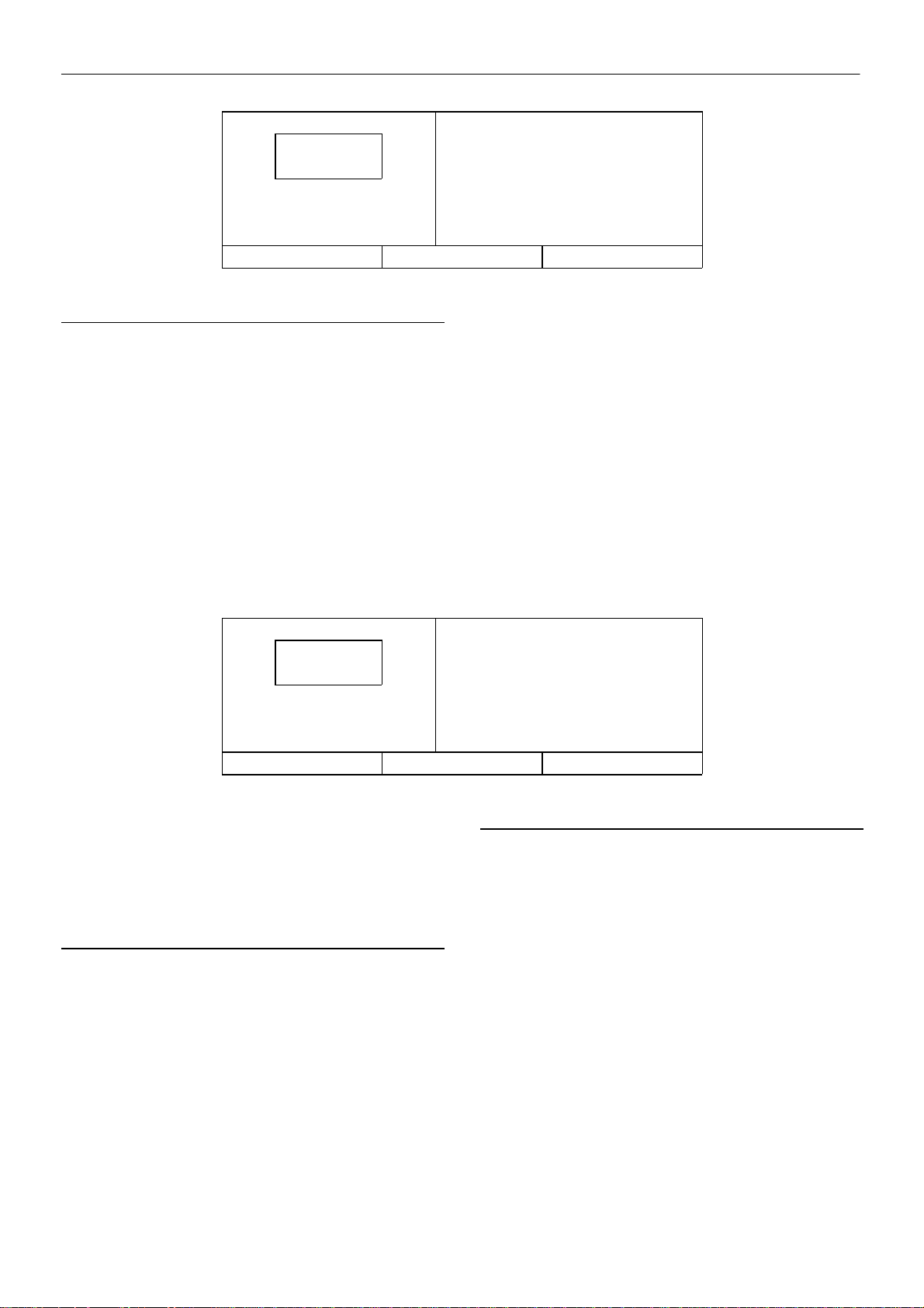
The display screen is divided into three functional areas, as seen
in the typical CURRENT STATUS screen shown here.
The left side continuously shows the package discharge pressure
in large numbers showing the running condition of the machine and the
line below that showing the present mode of operation.
The right side shows various items or lists such as the machine’s
CURRENT STATUS readings, the MAIN MENU, the OPERATOR
SETPOINTS list, etc. Any of the lists can be moved up or down by
pressing the arrow buttons to the right of the screen. The small arrow(s)
displayed i n the upper right corner of the screen indicate when you can
move up and/or down through a list. The arrow buttons are also used
to change an individual item’s value. At certain times, items and/or their
values are “highlighted”. This means that they are displayed as light
characters on a dark background.
barg
–CURRENT STATUS–
PACKAGE DISCHARGE TEMP
39_C
MAIN MENU
barg
7,5
RUNNING LOADED AIREND DISCHARGE TEMP
MODE: MOD/ACS 89_C
The bottom of the screen is divided into thirds with the words in each
small box showing the function of the button directly beneath it. The
words will change in these boxes depending on what actions are
permitted at any particular time. The action resulting from pressing
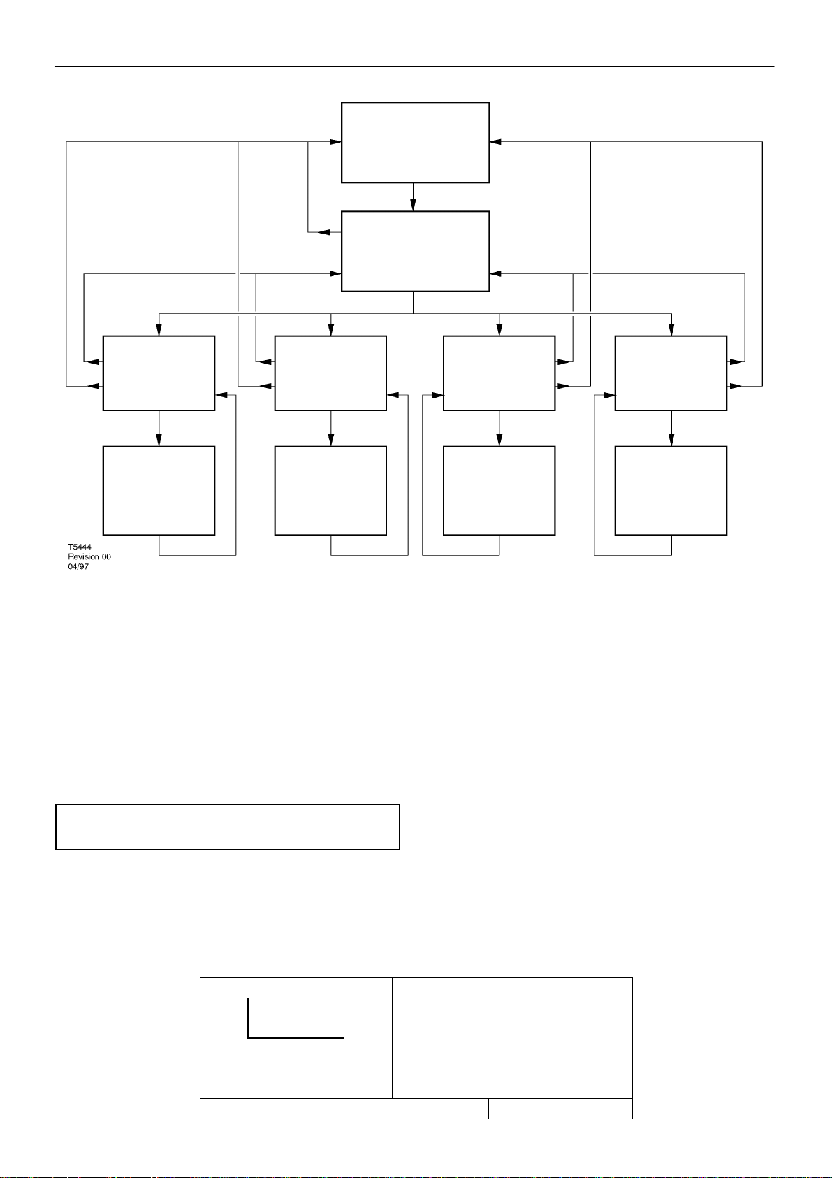
each of these buttons is indicated in the Operator Panel Flow Diagram
later in this section. This can be used as a quick reference of how to
step the controller screen through any desired function.
CURRENT STATUS
The CURRENT STATUS screen is considered to be the “normal”
display that the controller shows.
The following items and their present values can be displayed on the
right side of the screen by pressing the up and down arrow buttons.
barg
–CURRENT STATUS–
PACKAGE DISCHARGE TEMP
39_C
MAIN MENU
CURRENT STATUS items
Package Discharge Temperature
Airend Discharge Temperature
Injected Temperature
Sump Pressure
Separator Pressure Drop
Coolant Filter
Inlet Vacuum
Inlet Filter
Total Hours
Loaded Hours
% Load Modulation
Software Title and V ersion
M200–LV M250–LV
Page 27
OPERATING INSTRUCTIONS
CURRENT
STATUS
MAIN MENU
(1)
25
OPERATOR
SETPOINTS
(2)
OPERATOR
SETPOINTS ITEM
(3)
The controller automatically returns the display to this CURRENT
STATUS screen from other screens if no buttons are pressed within 30
seconds.
The MAIN MENU screen can be accessed from the CURRENT
STA TUS screen by pressing the MAIN MENU button, identified by the
words “MAIN MENU” in the bottom line of the screen directly above the
centre button.
OPTIONS
(2)
OPTIONS ITEM
(3)
SENSOR
CALIBRATION
(2)
SENSOR
CALIBRATION ITEM
(3) The UP and DOWN arrows will alter the value.
unchanged.
indicate acceptance.
(4) Depressing “Cancel” will exit the calibration mode.
(4)
Depressing “Cancel” will exit the edit mode and leave the value
Depressing “Set” will save the new value and flash the value to
Depressing “Calibrate” will calibrate the selected sensor.
ALARM HISTORY
(2)
ALARM HISTORY
ITEM
(3)
NOTE: Use the UP and DOWN arrows to move between selections.
Items will be highlighted in inverse display mode.
(1)Selecting the highlighted item will display the corresponding menu.
(2) Selecting the highlighted item will place the value in edit mode. This
is indicated by only the value being displayed in inverse display mode.
barg
7,5
READY TO START SENSOR CALIBRATION
STATUS SELECT
barg
Ensure that the unit is stopped and fully depressurised first.
(5)Use the UP and DOWN arrows to scroll through the list of status
items.
–MAIN MENU–
OPERATOR SETPOINTS
OPTIONS
ALARM HISTORY
M200–LV M250–LV
Page 28
26
OPERATING INSTRUCTIONS
MAIN MENU
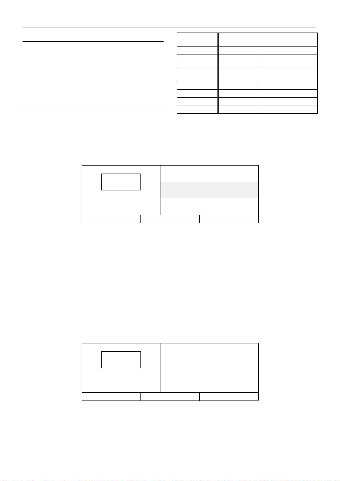
The MAIN MENU screen is the point from which various operator
functions can be accessed. Refer to the Operator Panel Flow Diagram.
Each of the functions can be chosen by using the up and down
arrows to highlight it on the screen.
The controller will go to the highlighted function if the SELECT
button i s pressed or will return to the CURRENT STATUS screen if the
STATUS button is pressed.
OPERATOR SETPOINTS
Setpoints are user–adjustable variables in the controller logic that
can be set using the OPERATOR SETPOINTS screen.
The name and value of each of the setpoints listed below can be
seen on the screen by moving the list up and down using the arrow
buttons.
barg
7,5
READY TO START ONLINE PRESSURE
STATUS MAIN MENU SELECT
barg
OPERATOR
SETPOINTS
Offline Pressure 75 to RATED +3 1 PSIG
Online Pressure 65 to OFFLINE
Mode of
Operation
Load Delay Time 0 to 60 1 SEC
Stop Delay Time 10 to 30 1 SEC
Star–Delta Time* 10 to 20 1 SEC
(Screen) Contrast 0 to 10 1
*Does not apply to automatic across the line starters.
–OPERATOR SETPOINTS–
OFFLINE PRESSURE
7,6 barg
6,9 barg
RANGE STEP UNIT
1 PSIG
– 10
MOD/ACS, ON/OFF LINE, MODULATION
ONLY
–––
Setpoints associated with options are described in the OPTIONS
sections.
A setpoint’s value can be changed by first highlighting the item and
its value and pressing the SELECT button to highlight just the value.
When the value line is highlighted by itself, the value can be adjusted
using the up and down arrow buttons. The CANCEL and SET buttons
appear at this time. Press the SET button to enter the new value or
press the CANCEL button to return the value of the setpoint prior to
using the arrows. The displayed value will flash twice to indicate that
it has been entered into the setpoint and the pair of setpoint item and
value display lines will again be highlighted together.
Operator set points can be exited by pressing the STATUS or MAIN
MENU buttons. If no buttons are pressed within 30 seconds, the display
will return to the CURRENT STATUS screen.
barg
7,5
READY TO START AUTO RESTART TIME
STATUS MAIN MENU SELECT
barg
–OPTIONS–
AUTO RESTART
Off
10 MINUTES
M200–LV M250–LV
Page 29
OPERATING INSTRUCTIONS
27
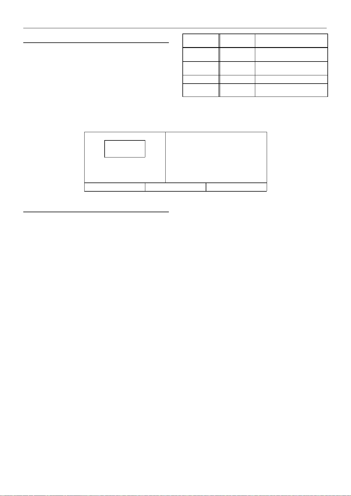
OPTIONS
Options are turned on or off and their associated values are set
using the OPTION screen.
Some op t i o n s r e q u i r e a d d i t i o n a l m a c h i n e h a r d w a r e a n d t h e c o r r e c t
“Option Module” to plug into the Intellisys controller. Descriptions of the
options operations can be found later in this section. The name and
value of each of the following options can be seen by moving the list up
and down using the arrow buttons.
barg
7,5
READY TO START SENSOR 3APT
STATUS MAIN MENU SELECT
SENSOR CALIBRATION
Pressure sensor calibration is done through the SENSOR
CALIBRATION screen. Sensor calibration can only take place when
the machine is stopped. Calibration needs to be done only after a
sensor has been replaced or the Intellisys controller has been
replaced.
barg
OPTIONS
Items
Power Out
Restart
Power Out
Restart Time
Low Ambient ON/OFF – –
Min. Cooler
Out Temp.
An Option item’s value can be changed the same way that
OPERATOR SETPOINTS values are changed.
–SENSOR CALIBRATION–
SENSOR 1AVPT
CALIBRATE
CALIBRATE
Range Step Unit
ON/OFF – –
10 to 120 1 SEC
30 to 150 1 Deg.F
Each of the sensors listed below can be chosen by using the up and
down arrow buttons to highlight it on the screen.
SENSOR CALIBRATION Items
Sensor 1AVPT
Sensor 3APT
Sensor 4APT
Select the highlighted sensor by pressing the SELECT button.
Press the CALIBRATE button to start the automatic calibration
procedure, or press the CANCEL button to not calibrate it and return
to the sensor list.
The calibration screen can be exited by pressing either the STA TUS
or MAIN MENU buttons. If no buttons are pressed within 30 seconds,
the display will return to the CURRENT STATUS screen.
M200–LV M250–LV
Page 30
28
OPERATING INSTRUCTIONS
barg
7,5
READY TO START ALARM HISTORY 2
STATUS MAIN MENU SELECT
barg
–ALARM HISTORY–
ALARM HISTORY 1
MAIN MOTOR OVERLOAD
HIGH AIREND DISCH TEMP
ALARM HISTORY
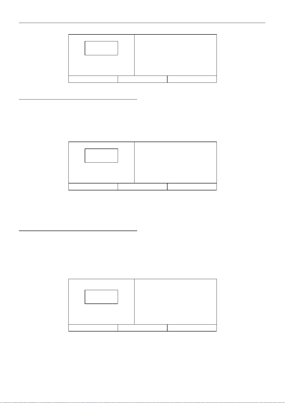
Alarm History displays each of the Alarm messages for the last 15
Alarms experienced by the machine. It also gives access to displaying
the machine operating conditions that existed at the time of each Alarm.
The first one shown, “Alarm History 1”, was the most recent Alarm to
occur. Note that multiple, consecutive EMERGENCY STOP Alarms
are not recorded as separate Alarms, only the first one will be shown.
barg
7,5
READY TO START PACKAGE DISCHARGE TEMP
STATUS MAIN MENU ALARM HIST.
The name and value of each of the items listed below can be seen
by moving the list up and down using the arrow buttons. Pressing the
ALARM HIST. button will return the display to the ALARM HISTORY
screen.
ALARM HISTORY Items
Package Discharge Pressure
Package Discharge Temperature
Airend Discharge Temperature
Injected Temperature
Sump Pressure
barg
Each of the last 15 Alarm messages can be seen by moving the
Alarm History list up and down using the arrow buttons. Pressing the
SELECT button when one of the Alarms is highlighted will display the
list of machine values that existed at the time that particular Alarm
occurred.
–ALARM HISTORY 1–
PACKAGE DISCH PRESSURE
13,7 barg
54_C
Separator Press. Drop
Coolant Filter
Inlet Vacuum
Inlet Filter
Total Hours
Loaded Hours
% Load Modulation
Alarm histories can be exited by pressing either the STATUS or
MAIN MENU buttons. If no buttons are pressed within 30 seconds, t h e
display will return to the CURRENT STATUS screen.
barg
7,5
RUNNING UNLOADED PRESS RESET TWICE
MODE: MOD/ACS
STATUS MAIN MENU RESET
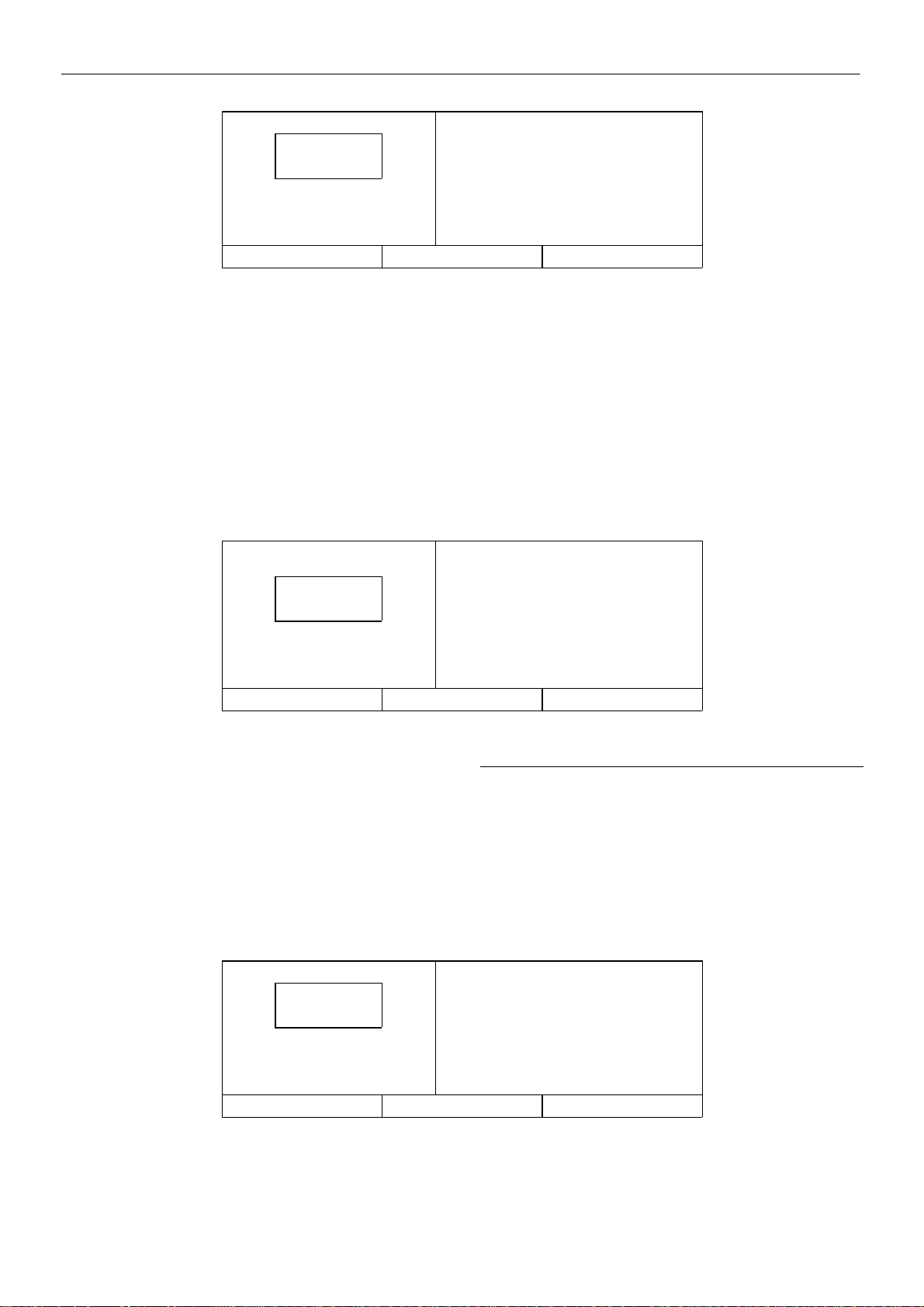
When a Warning occurs, the word WARNING will flash on the
display screen and appear in large letters as shown above. The display
message will indicate what caused the warning.
If multiple Warnings exist, the small up/down arrows will appear in
the upper right corner of the display screen. The multiple Warnings can
be seen by pressing the up and down arrow buttons. Pressing the
STATUS button will display the CURRENT STATUS screen with the
WARNING button indicating that a Warning still exists.
M200–LV M250–LV
barg
WARNING
CHANGE INLET FILTER
Page 31
OPERATING INSTRUCTIONS
–CURRENT STATUS–
barg
7,5
RUNNING UNLOADED AIREND DISCHARGE TEMP
MODE: MOD/ACS 89,4_C
WARNING MAIN MENU
barg
PACKAGE DISCHARGE TEMP
39,4_C
29
Pressing the WARNING button will return the display to the
WARNING screen and the RESET button.
A W arning needs to be reset by the operator by pressing the RESET
button twice.
The possible Warning messages are as follows;
AIREND DISCHARGE TEMP – This will occur if the Airend Discharge
(2ATT) exceeds 97% of the alarm limit, 228_F (109_C) and is not
adjustable.
barg
7,5
STOPPED BY ALARM
MODE: MOD/ACS PRESS RESET TWICE
STATUS MAIN MENU RESET
HIGH DISCHA R G E P R E S S – This can occur if the machine’s loading
function i s being controlled by a host device such as a sequencer or an
ISC. This warning will occur when the package discharge pressure is
above the maximum offline pressure (rated pressure plus 3 psig (0,2
bar)) for more than 3 seconds. This warning will cause the compressor
to unload. The host device will not be able to load the compressor until
the package discharge pressure falls to the rated pressure of the
machine.
SENSOR F AILURE 4ATT – This will occur if the Package Discharge
Temperature Sensor (4ATT) is missing or broken.
barg
CHANGE COOLANT FIL TER – This warning will occur if the high side
pressure is 20 psig (1,4 bar) greater than the low side pressure of 1
DPS and the Injected Coolant temperature (2CTT) is greater than
120_F (49_C).
CHANGE INLET FIL TER – This will occur if the Inlet Vacuum (1AVPT)
is greater than 0,7 psig (0,05 bar) and the machine is fully loaded (inlet
valve is completely open).
CHANGE SEPR ELEMENT – This warning will occur if the pressure
on the Separator (3APT) is 15 psig (1,0 bar) greater than the pressure
at the Package Discharge (4APT) and the machine is fully loaded.
ALARM
HIGH AIREND DISCH TEMP
109,4_C
ALARMS
When an Alarm occurs, the word ALARM will flash on the display
screen and appear in large letters as shown above. The display
message will indicate what caused the Alarm.
Pressing the STATUS button will display the STATUS screen. The
presence of the ALARM button indicates that an Alarm condition still
exists. Alarm Status is the list of machine operating conditions that
existed at the time of the Alarm.
barg
7,5
STOPPED BY ALARM PACKAGE DISCHARGE TEMP
MODE: MOD/ACS 39,4_C
ALARM MAIN MENU
The name and value of each of the items listed can be seen by
moving the list up and down using the arrow buttons. Pressing the
ALARM button will return the display to the Alarm screen and the
RESET button.
The Alarm needs to be reset by the operator by pressing the RESET
button twice. Any exceptions to this are explained in the alarm
descriptions.
barg
–ALARM STATUS–
PACKAGE DISCH PRESSURE
7,5 barg
The possible Alarm messages are as follows;
CHECK INLET CONTROL – This will occur if the machine is unloaded
and the inlet vacuum is less than 3 psig (0,2 bar).
M200–LV M250–LV
Page 32
30
OPERATING INSTRUCTIONS
CHECK INLET CTRL SYS – This will occur if the inlet butterfly valve
is in an incorrect position.
CHECK MOTOR ROT ATION – This will occur if the machine is started
and the compressor has incorrect rotation.
CONTROL POWER LOSS – This will occur if the controller detects a
loss of the 110 VAC control power.
EMERGENCY STOP– This will occur if the Emergency Stop button is
engaged. The button must be disengaged before the alarm can be
cleared.
FAN MOTOR OVERLOAD– This will occur if a fan motor overload is
sensed.
HIGH AIREND DISCH TEMP– This will occur if the airend discharge
temperature is greater than 228_F (109_C).
LOW SUMP AIR PRESSURE– This will occur if the machine is running
fully loade d and the sump pressure drops below 20 psig (1,4 bar).
LOW UNLOAD SUMP PRESS– This will occur if the machine is
running unloaded and the sump pressure is less than 15 psig (1,0 bar)
for 15 seconds.
MAIN MOTOR OVERLOAD– This will occur if a drive motor overload
is sensed.
MEMORY FAULT– This will occur if the controller has determined
some of the data stored in memory contains unacceptable values.
When this occurs, the sensors should be calibrated and all the set
points checked. It is normal for this alarm to occur after changing
controller software.
REMOTE S TART FAILURE– This will occur if the Remote Start button
is pressed after the machine is running or if the Remote Start button
remains closed.
REMOTE STOP FAILURE– This will occur if the Remote Stop button
remains open and either Start button is pressed.
SENSOR FAILURE 1AVPT (or 3APT, 4APT, 2CCT, 2ATT)– This will
occur if a sensor is recognised as missing or broken. This does not
apply to sensor 4ATT.
STARTER FAULT– This will occur if the starter contacts open while the
machine is running. It will occur if the machine is given the stop
command and the starter contacts do not open.
STEPPER LIMIT SWITCH– This will occur if both limit switches are
activated a t the same time.
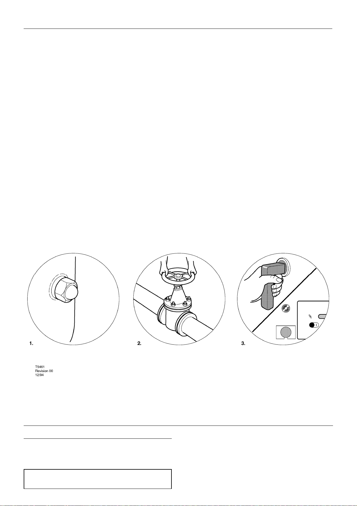
PRIOR TO STARTING
Refer to the diagram T5461
WARNING: Ensure that all protective covers/guards are in place
before attempting to start the machine.
M200–LV M250–LV
1: Check the coolant level in the sight tube/glass. Add coolant if
necessary.
2: Ensure that the discharge air isolation valve is open.
3: Switch on the main electrical isolation switch. The power on
indicator will illuminate, indicating that the line and control voltages are
available.
Page 33
OPERATING INSTRUCTIONS
31
STARTING THE MACHINE
Refer to the diagram T5443
Upon power up, the Intellisys will carry out a series of checks, and
the message CHECKING MACHINE will show on the display. If all the
check parameters are satisfactory, the display will then show READY
TO START.
Depress the start button (2) on the Intellisys unit. The machine will
start and automatically load.
STOPPING THE MACHINE
Refer to the diagram T5443
Depress the STOP button (3) which will automatically unload the
compressor for 10 seconds before stopping.
Switch off the main electrical isolation switch.
STOPPING THE MACHINE IN AN EMERGENCY
Refer to the diagram T5443
If the machine has to be stopped in an emergency DEPRESS THE
EMERGENCY STOP BUTTON (1) LOCATED ON THE
INSTRUMENT PANEL.
RE–STARTING AFTER AN EMERGENCY
If the unit has been switched off because of a machine malfunction,
then identify and correct the fault before attempting to re–start.
If the unit has been switched off for reasons of safety , then ensure
that the machine can be operated safely before re–starting.
Refer to the PRIOR TO STARTING and STARTING THE
MACHINE instructions earlier in this section before re–starting the
machine.
This will over–ride the normal unload/stop button and will
immediately stop the machine without the 10 second delay.
CAUTION: Never allow the machine to stand idle with pressure in the
system.
M200–LV M250–LV
Page 34
32
AIRCARE WARRANTY
Superior Service Solutions for Air Systems
AirCare is a responsive and flexible contract maintenance program custom designed for the owner who requires planned maintenance for increased
system reliability.
The AirCare program provides you with reduced maintenance costs, reduced energy usage through optimization and efficiency, and reduced production losses through fewer unexpected maintenance requirements and downtime. An optional feature, Intelliguard is used to reduce downtime by remote
monitoring.
AirCare Options
Unit Status Coverage Service Level
Inspection and diagnostic service only or
Sign up for AirCare within the warranty period Five Year Drivetrain or Package coverage
To enroll in AirCare or Intelliguard, contact your local Ingersoll–Rand representative today.
Preventative maintenance and diagnostic
service
M200–LV M250–LV
Page 35
MAINTENANCE
33
PERIOD MAINTENANCE
After 24 hours Visual check of machine for any leaks, dust
Daily Check the coolant level and replenish if
When the separator Check the pressure differential.
element warning is
displayed.
First 150 hours Change the coolant filter.
1 month Check the operation of the high temperature
1 month Check the operation of the discharge
1 month Check the cooler(s) for build up of foreign
1 month Check the operation of the float mechanism
Each 3 months Operate the safety valve manually to verify
Each 3 months Check all hoses for signs of deterioration,
Each 2000 hours / 6
months
build up or unusual noise/vibration.
Contact IR authorised distributor if in doubt.
necessary.
Change the separator element if the
pressure drop is zero or exceeds 1 bar (15
p.s.i.g.)
protection switch(es) (109_C standard).
temperature sensor (109oC standard). The
sensor should alert at 106oC.
matter. Clean if necessary by blowing out
with air or by pressure washing.
in the moisture separator and clean if
necessary.
that the valve mechanism is functioning
correctly and that a small amount of air is
released.
cracks, hardening etc.
Change the coolant filter.
PERIOD MAINTENANCE
2000 hours / 6
months
2000 hours / 6
months
1 year Change the air filter element.
1 year/1000 hours or
as defined by local
or national
legislation.
4000 hours / 6
months
2000 / 4000 hours Lubricate the main motor bearings according
8000 hours / 2 years
4 years Replace all hoses.
6 years/6000 hours
or as defined by
local or national
legislation.
1 monthly intervals. On water cooled and sea water cooled
Take coolant sample for fluid analysis.
Check scavenge screen for blockage, clean
if required.
Replace the element sooner if the indicator
light flashes.
Separator tank.
Fully inspect all external surfaces, welds a n d
fittings. Report any excessive corrosion,
mechanical or impact damage, leakage or
other deterioration.
Check the operation of the blow down
solenoid valve for signs of fatigue. Renew
the seals if necessary.
to information on the motor data plate.
If in doubt contact Ingersoll–Rand.
Replace the ULTRA COOLANT at
whichever interval occurs first.
Also replace the separator element and
coolant filter.
Separator tank.
Remove the cover plate and any necessary
fittings. Clean the interior thoroughly and
inspect all internal surfaces and welds.
models check the water input line strainer for
build u p o f foreign matter, clean if required
Note:
On some sea water cooled models the oil cooler and after cooler are fitted with sacrificial zinc anodes (pencils) that are located in the end bonnets of
the coolers. These sacrificial zinc anodes should be checked after the first 50 hours of operation to determine if corrosive conditions exist. If satisfactory
this interval may be extended to 500 hours.
NOTE:
1 If sacrificial zinc anode is 50% corroded it should be replaced.
2 Coastal/harbour waters can contain corrosive chemicals from pollution and may reduce anode/cooler life.
3 Effects of corrosion or erosion are specifically excluded from warranty considerations.
M200–LV M250–LV
Page 36

34
MAINTENANCE
ROUTINE MAINTENANCE
This section refers to the various components which require
periodic maintenance and replacement.
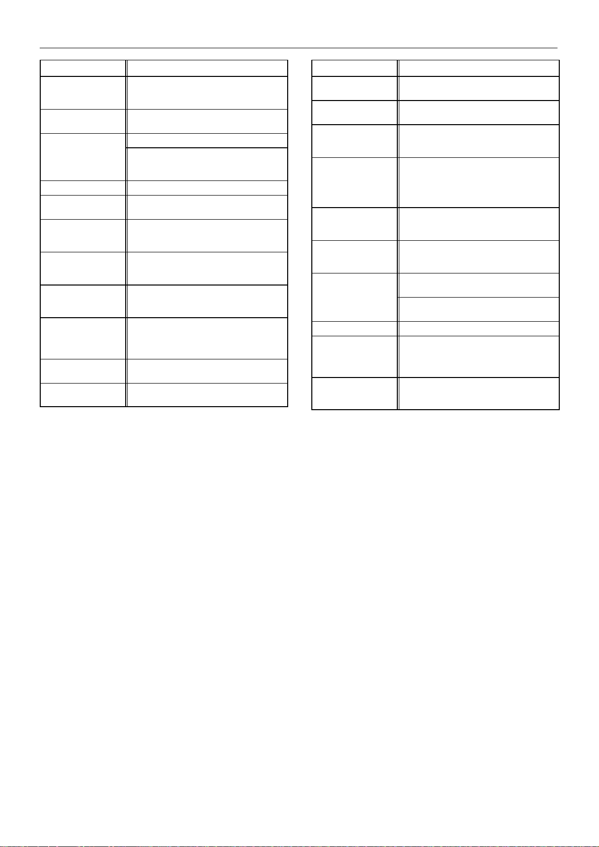
The SERVICE/MAINTENANCE CHART indicates the various
components’ descriptions and the intervals when maintenance has to
take place. Coolant capacities, etc., can be found in the GENERAL
INFORMATION section of this manual.
Compressed air can be dangerous if incorrectly handled. Before
doing any work on the unit, ensure that all pressure is vented from the
system and that the machine cannot be started accidentally .
Ensure that maintenance personnel are adequately trained,
competent and have read the Maintenance Manuals.
Prior to attempting any maintenance work, ensure that:–
. all air pressure is fully discharged and isolated from the system. If
the automatic blowdown valve is used for this purpose, then allow
enough time for it to complete the operation.
. the machine cannot be started accidentally or otherwise, by posting
warning signs and/or fitting appropriate anti–start devices.
. all residual electrical power sources (mains and battery) are
isolated.
. all panels are replaced, canopy and doors closed.
. hazardous materials are effectively contained and disposed of.
WARNING
Do not under any circumstances open any drain valve or remove
components from the compressor without first ensuring that the
compressor is FULLY SHUT– DOWN, power isolated and all air
pressure relieved from the system.
COOLANT LEVEL CHECKING PROCEDURE
The coolant level should be checked daily. Located on the side of
the separator is a coolant level sight tube/glass. Whilst the compressor
is running under load and the coolant is at normal operating
temperature, the coolant level should be between the midd le and the
top of the sight glass.
COOLERS
Once a month, the coolers should be checked for coolant and dirt
accumulation on the exterior surfaces. Clean the coolers by directing
compressed air carrying, if possible, a non–flammable safety solvent
through the core of the cooler.
COOLANT FILTER CHANGE PROCEDURE
. Loosen filter element with the correct tool.
Prior to opening or removing panels or covers to work inside
a machine, ensure that:–
. anyone entering the machine is aware of the reduced level of
protection and the additional hazards, including hot surfaces and
intermittently moving parts.
. the machine cannot be started accidentally or otherwise, by posting
warning signs and/or fitting appropriate anti–start devices.
Prior to attempting any maintenance work on a running
machine, ensure that:–
. the work carried out is limited to only those tasks which require the
machine t o run.
. the work carried out with safety protection devices disabled or
removed i s limited to only those tasks which require the machine to be
running with safety protection devices disabled or removed.
. all hazards present are known (e.g. pressurised components,
electrically live components, removed panels, covers and guards,
extreme temperatures, inflow and outflow of air, intermittently moving
parts, safety valve discharge etc.).
. appropriate personal protective equipment is worn.
. loose clothing, jewellery, long hair etc. is made safe.
. Remove the element from the housing.
. Place the old element in a sealed bag and dispose of in a safe way.
. Clean the mating face of the housing.
. Remove the new Ingersoll–Rand replacement element from its
protective package.
. Apply a small amount of lubricant to the element seal.
. Screw the new element down until the seal makes contact with the
housing, then hand tighten a further half turn.
Check the coolant level, refilling if necessary.
. Start the compressor and check for leaks.
COOLANT CHANGE PROCEDURE
It is better to drain the coolant immediately after the compressor has
been operating as the liquid will drain more easily and any contaminant
will still be in suspension.
WARNING:
Extreme care should be taken when draining hot lubricant.
. warning signs indicating that Maintenance Work is in Progress are
posted in a position that can be clearly seen.
Upon completion of maintenance tasks and prior to returning
the machine into service, ensure that:–
. the machine is suitably tested.
. all guards and safety protection devices are refitted.
M200–LV M250–LV
To enable the coolant to be drained, a valve is located under the
separator tank. This in turn feeds a flexible hose to enable direct
discharge to suitable containers for coolant removal.
Open the valve and completely drain the coolant into a suitable
container.
Close the valve and refill the compressor .
CAUTION – DO NOT MIX OILS WITH SSR ULTRA COOLANT.
Page 37
MAINTENANCE
35
. Start the compressor and check for leaks.
. Check the coolant level, refilling if necessary.
. Dispose of waste coolant in accordance with local and
governmental regulations.
NOTE
Shorter coolant drain intervals may be necessary if the compressor
is operated in adverse conditions.
AIR FILTER CHANGE PROCEDURE
Removal
WARNING: Do not remove the filter(s) without first making sure
that the machine is stopped and the system has been completely
relieved of all air pressure. (Refer to STOPPING THE MACHINE in
the OPERATING INSTRUCTIONS section of this manual).
Remove the wing-nuts securing the filter cover and remove the
housing lid.
Fit the new element(s) and re–assemble the components in reverse
order.
SEPARATOR ELEMENT CHANGE PROCEDURE
Remove the roof panel to gain access to the top of the separator
tank.
MOTOR BEARINGS
Clean the area around the grease nipple and remove the protective
cover. Add the correct amount of grease (refer to the
SERVICE/MAINTENANCE CHART earlier in this section). Replace
the protective cover and clean the area of surplus grease.
MOTOR BEARING LUBRICANT SPECIFICATION
Use ESSO UNIREX N3 grease or equivalent.
CAUTION:
Do not over pack the motor bearings with grease as this may lead
to motor failure.
CAUTION:
Ensure dirt and/or other contaminants are not introduced into the
bearing during the greasing process.
H.A.T. SENSOR CHECKING PROCEDURE
It is recommended that the discharge temperature sensor is
checked regularly as follows:
AIr cooled machines
Stop the cooling fan by opening the fan motor circuit breaker.
Water cooled machines
Shut off the cooling water .
.Disconnect the scavenge tube from the airend and loosen the fitting
that secures the scavenge tube to the separator tank cover and then
remove the scavenge tube.
Disconnect the blowdown system hose assembly and the minimum
pressure valve.
. Remove the setscrews securing the cover to the tank and remove
the complete cover assembly.
. Withdraw the used element, place it in a sealed bag and dispose of
it safely.
. Clean the gasket surface on both the tank and the cover.
CAUTION
Do not use any form of sealant on either the separator tank or the
separator tank cover faces.
WARNING
Do not remove the staple from the anti–static gasket on the
separator element since it serves to ground any possible static
build–up.
. Install the replacement element.
The machine should trip at 109_C standard.
CAUTION:
Under no circumstances should these discharge temperatures be
exceeded. If the machine fails to trip A FAULT EXISTS. Investigate
immediately.
The temperature at which the machine stops should be recorded for
comparison with future results.
.Re–assemble the components in reverse order.
. Start the compressor and check for leaks.
AIREND BEARINGS
Airend bearings are lubricated by the compressor coolant and
require n o maintenance.
M200–LV M250–LV
Page 38
36
FAULT FINDING
FAULT CAUSE REMEDY
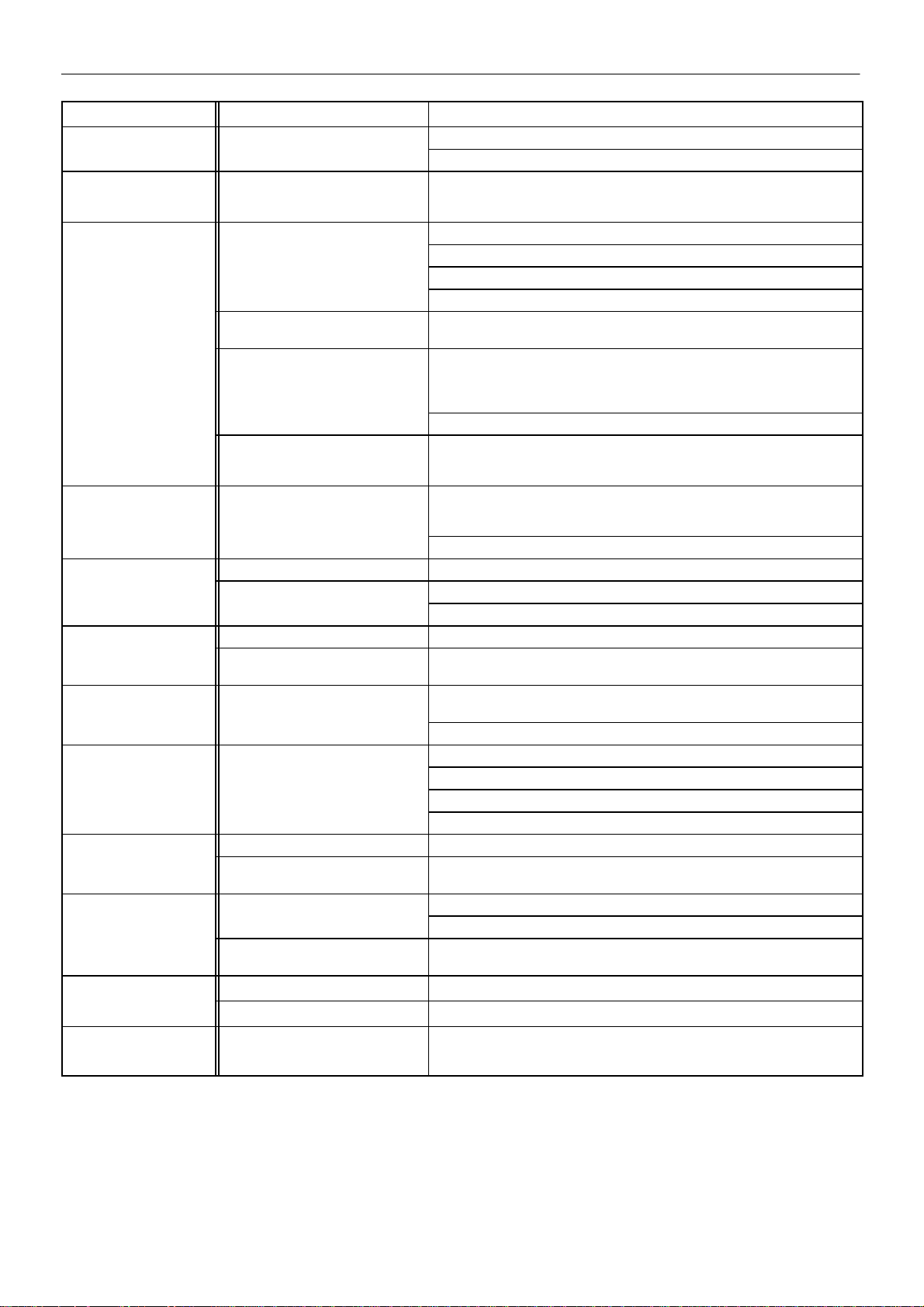
’Power on’. L.E.D. does CONTROL VOLTAGE NOT Check the control fuses.
not illuminate. AVAILABLE
Controller indicates trip
condition.
Compressor trips INSUFFICIENT COOLANT Check the coolant level.
indicating a high
compressor
compressor
temperature.
Compressor trips and
indicates
motor overload.
Compressor shutdown. ISOLATION VALVE CLOSED. Open the valve and restart.
Display shows
OVERPRESSURE.
OVERPRESSURE.
Compressor will not DEMAND TOO HIGH Check for leaks, open service valves or exceptionally high demand.
build up rated pressure.
Compressor will not
load.
Compressor fails to – Check the operation of the inlet valve.
deliver rated
capacity.
capacity.
Excessive coolant BLOCKED SCAVENGE LINE Clear the blockage.
consumption.
Rapid cycling or RAPID LOAD/UNLOAD CYCLING Duty cycle too rapid – Increase system capacity.
receiver will not
blow–down to unloaded
blow–down to unloaded
running pressure.
Safety valve blows MPV STUCK CLOSED Strip MPV, examine and repair if necessary.
when compressor goes
on load.
Compressor trips indicating a high compressor temperature.
CONTROL CIRCUIT
INTERRUPTED BY A SAFETY
DEVICE
CIRCULATION
POOR ELECTRICAL
CONNECTION
INSUFFICIENT COOLING TAKING
PLACE
EXCESSIVELY HIGH AMBIENT
TEMPERATURE
(i.e. greater than 46oC (115oF).
EXCESSIVE CURRENT HAS
CAUSED THE THERMAL
OVERLOAD (MOL) TO TRIP
BLOWDOWN SYSTEM Check the operation of the load solenoid.
INEFFECTIVE.
OFFLINE PRESSURE SET TOO
LOW
INLET VALVE NOT OPENING Ensuring that all power to the machine is switched off, check that the valve is free
RUPTURED OR FOULED
SEPARATOR ELEMENT
MINIMUM PRESSURE VALVE
(MPV) STUCK OPEN
SAFETY VALVE FAULTY Check the setting of the safety valve and the rated pressure.
INSUFFICIENT COOLING TAKING
PLACE
Check the transformer secondary windings for the control voltage.
Check machine for indicated fault. Attempt to ’reset’ the controller. If the fault
persists investigate further.
Check that the coolers are clean.
Check the coolant system for blockages.
Check the operation of thermostatic valve.
H.A.T. thermistors fail-safe. The unit will trip due to open or short circuit.
Check that the cooling air flow is not obstructed at:
. The inlet grille
. The cooler matrix
. The exhaust vents
Check that the ducting (if fitted) is the correct size.
Improve the ventilation to the compressor room.
Check the actual operating pressure and lower the setting if it is too high. Isolate
the electrical supply and check that the airend and motor rotate freely . Check the
separator element for excessive pressure drop.
Check that the mains voltage is not below the specified value.
Check the operation of the unloader valve – strip and clean if necessary.
Check the offline pressure setting.
to open.
Check the operation of the stepper motor.
Check the operation of the stepper motor.
Check the offline/online pressure setting.
Check the inlet filter for contamination. The L.E.D. should indicate if it is blocked.
Change the element.
Change the Intellisys controller to show modulation operation.
Strip the MPV , examine and repair if necessary.
If machine is water cooled or seawater cooled, check that the cooling water is
flowing. Check that there is no air in the water cooling system. Check that the
strainer is not blocked.
M200–LV M250–LV
 Loading...