

Ingersoll-Rand EL 24V DC Series Maintenance Information

45530136
July 2008
Electric Screwdrivers
EL 24V DC Series
Maintenance Information
Edition 1
Save These Instructions
2 45530136_ed1
WARNING
Always wear eye protection when operating or performing maintenance on this tool.
NOTICE
Off
NOTICE
NOTICE
Always turn o the air supply and disconnect the air supply hose before installing, removing or adjusting any accessory on this tool or
before performing any maintenance on this tool.
Note: When reading the instructions, refer to exploded diagrams in parts Information Manuals when applicable (see under Related Documentation
for form numbers).
Disassembly
Disassembly of the Housing
To disassemble the Housing (1 or 44), begin by unscrewing the
1.
connection ring to remove the Power Cord (6 or 55).
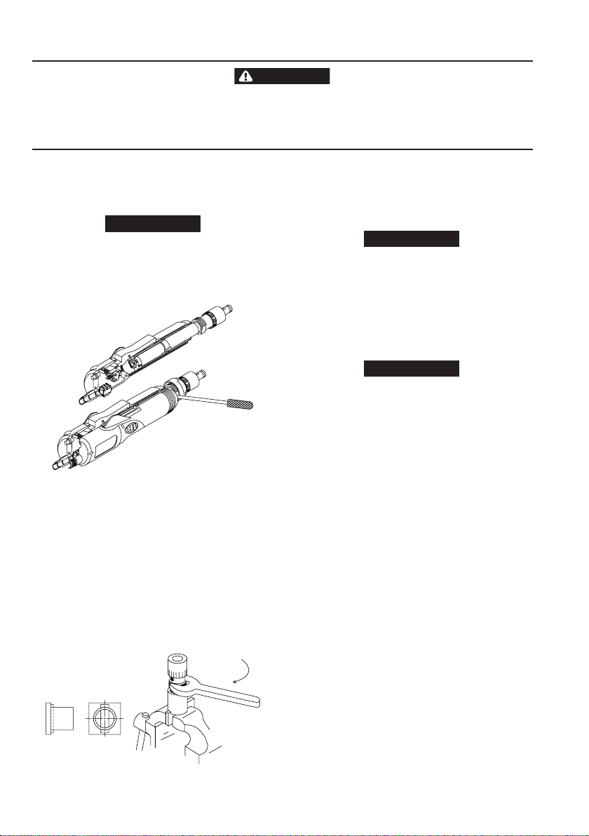
Use a 29 mm open end wrench to unscrew the Coupling (56 or 6).
2.
This is a left-hand thread.
3. Using a #1 phillips screwdriver, remove the Housing
Screws (2 or 45).
4. Separate the Housing by lifting the half with the three screw
holes. If necessary, use a small screwdriver to pry the Housing
apart. Refer to Dwg. TPD1816.
(Dwg. TPD1813)
5. Remove the Trigger (17 or 51), Trigger Spring (18 or 52) and the
Trigger Pin (19 or 53).
6. Remove the Housing Bush (7 or 54) from the back of the tool.
Disassembly of the Clutch Housing and Gear Case
1. Lift the Clutch Housing (53 or 8), Gear Case (37 or 22) and Motor
Assembly from the Housing. While holding rmly, pull the Gear
Case away.
2. Tap the end of the Gear Case on the work bench to remove the
Motor Clamp Spacer (36 or 23) and the Gear Head Assembly
(38 or 20).
3. Remove the Gear Head Planet Gears (39 or 21) from the Gear
Head.
4. Remove the Push Rod (46 or 17) from the Gear Case. Fit the two
notches at the rear end of the Gear Case into the Gear Case
Fixture part no. EL0410B-J37. Refer to Dwg. TPD1813.
(Dwg. TPD1813)
5. Using a slotted screwdriver, remove the Front Bit Retainer
Retaining Ring (60 or 3) from the Bit Holder Assembly (48 or 12).
6. Remove the Bit Retainer Sleeve (58 or 4) and Bit Retainer Sleeve
Spring (59 or 5).
7. Remove the two Bit Retaining Balls (50) from the Bit Holder by
tapping the Bit Holder on the work bench.
Model EL0109 has only one Bit Retaining Ball (11).
8. Unscrew and remove the Clutch Adjusting Ring (57 or 1) from
the Clutch Housing. For Model EL0109B, also remove the Bit
Retainer Spring (2).
9. Remove the three Clutch Adjusting Pins (54 or 7) from the Clutch
Housing and the Bit Retainer Sleeve Spring.
10. Remove the Bit Retainer Retaining Ring (55) using external snap
ring pliers.
11. Using a 21 mm open end wrench on the ats of the Clutch
Housing Assembly, unscrew and remove the Clutch Housing.
This is a left-hand thread.
12. Remove the Clutch Spring Plate (52 or 9) and the Clutch Spring
(51 or 10).
13. Lift the Bit Holder Assembly from the Gear Case. For Model
EL0109B, remove the Cam Guide (13) and the two Cam Guide
Balls (14) from the Bit Holder, For Models EL1007 and EL0410,
remove the two Cam Guide Balls (49) and the Cam Guide
Sleeve (47) from the Bit Holder Assembly (48).
14. Remove the Gear Case from the Gear Case Fixture. Turn it over
and push the Spindle Assembly (40 or 18) from the Case.
15. Remove the Spindle Planet Gears (41 or 19) from the Spindle
Assembly.
16. For Model EL0109, remove the Cam (16) and Cam Guide Sleeve
Assembly (15) from the bearing. For Model EL1007, remove the
Cam Collar (45), the Cam (43), two Cam Pins (44) and the Thrust
Washer (42).
Cleaning and Inspection of the Tool
1. Clean all mechanical parts you have disassembled in an approved
safety solvent in a well-ventilated area. Inspect for damage or
wear.
2. For all Models, inspect the Bit Holder Assembly. If the bearing
does not rotate smoothly, replace the Bit Holder Assembly.
3. Inspect the Cam. If it is worn, replace it.
4. For Model EL1007, inspect the Cam Pins (44). If they are worn,
replace them.
5. For Model EL0109, inspect the Cam Guide Sleeve. If the bearing
of the Cam Guide Sleeve does not rotate smoothly, replace it.
6. Inspect all the Gear Head Planet Gears. If the teeth are worn or
damaged, replace them.
7. Inspect the Gear Case. If the inner gear teeth are worn or
damaged, replace them.
8. Inspect the Spindle Assembly. If the bearing does not rotate
smoothly, replace the Spindle Assembly.
Disassembly and Inspection of the Motor
1. Remove the Motor Assembly, the Plunger (13 or 37) and the
Plunger Spring (14 or 38) from the Housing.
2. Using a thin slotted screwdriver, release the tension on the Brush
NOTICE
NOTICE
NOTICE
NOTICE
NOTICE
NOTICE
NOTICE
Spring (25 or 35) and remove the two Brush Assemblies (24 or 33)
from the Rear End Plate (23 or 32).
3. Carefully pull the copper wires to remove the Brush Assemblies.
Be careful not to damage the wires.
If the Brush Assemblies need to be replaced, desolder the blue and
red Motor wires and remove the Brush Screws (26 or 34).
4. Using a thin blade screwdriver, remove the Motor Assembly
Springs (34 or 31) by inserting the screwdriver between the
Springs and the Rear End Plate and prying upward.
5. Remove the Front End Plate (33 or 24) from the Field (32 or 25).
6. Remove the Rear End Plate and the Motor Plate (27 or 30) by
inserting a slotted screwdriver into the space between the Rear
End Plate and the Field and prying upward.
7. While pushing the Rear Armature Bearing (28 or 29), pull the
Armature (31 or 26) from the Field.
Do not damage the commutator or windings on the Armature.
Hold the Armature body, not the commutator, when removing.
8. Remove the Push Rod (35 or 36) from the Armature.
9. Inspect the Push Rod. If it is worn, replace it.
10. Inspect the Rear Armature Bearing. If it does not rotate smoothly,
replace it.
11. Inspect the gear teeth on the Armature. If they are worn or
damaged, replace the Armature.
12. Inspect the front Armature Bearing. If it does not rotate smoothly,
replace the Armature.
13. Inspect the commutator, If it is worn, replace the Armature.
14. Clean the Armature, Field, Motor Plate and the End Plates using a
piece of ne cloth. For excess contamination, spray with contact
cleaner and brush if necessary.
Disassembly and Inspection of the Electronics
1. To remove the Trigger Switch (8 or 50), Reverse Switch (9 or 48)
or Brake Switch (15 or 42), remove any screws and pull the Switch
from the Housing. Desolder and remove the lead wires.
2. To remove the Insulator (71 or 49), desolder the lead wires.
Assembly
Assembly of the Electronics
Before soldering any wire, slip a piece of heat shrinkable tubing
over the wire.
1. To assemble the Electronic Components, resolder all wires to the
Insulator (71 or 49). Also resolder all wires to the Brake Switch
(15 or 42) and the Trigger Switch (8 or 50).
2. Reattach the Brake Switch to the Switch Plate (10 or 39) and
screw the Plate into the Housing (1 or 44).
3. Insert all electronic components into their proper locations.
Refer to Dwg. TPD1817 on page 13.
Be sure the notch in the Insulator ts with the tab in the Housing.
Assembly of the Motor
1. Carefully insert the gear end of the Armature (31 or 26) into the
notched side of the Field (32 or 25).
Be careful not to damage the commutator or windings.
2. Install the Front End Plate (33 or 24) onto the Field.
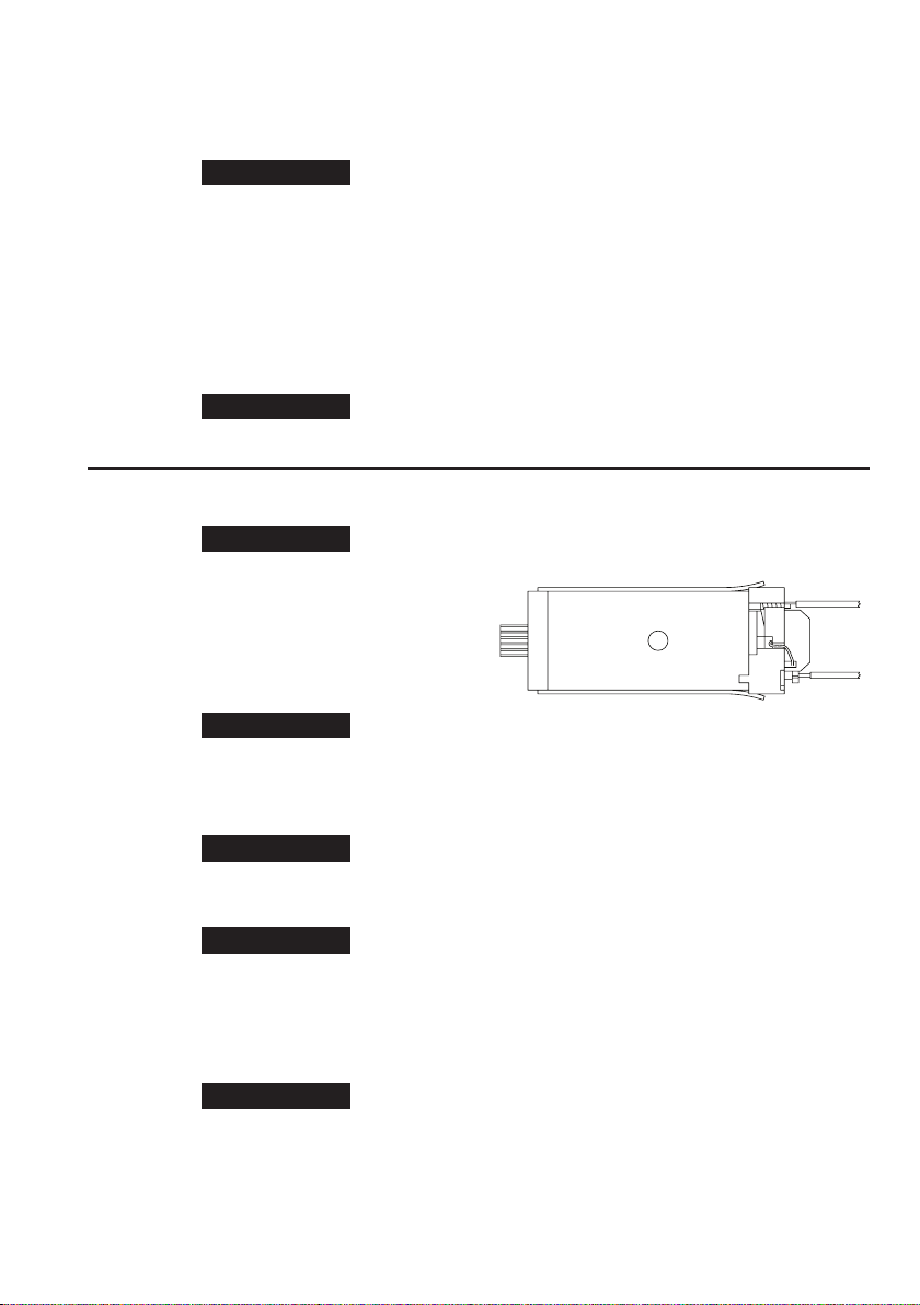
3. Place the Motor Plate (27 or 30) onto the Rear End Plate (23 or 32).
Be sure to install the Motor Plate correctly. The edge of the Motor
Plate must be parallel to the step in the Rear End Plate.
4. Push the Rear End Plate into the notches of the Fields.
5. Snap the Motor Assembly Spring (34 or 31) into notches of the
End Plates.
6. Insert the Brush Assembly (24 or 33) into the Rear End Plate. Be
careful not to twist or damage the copper wire.
Make sure the Brush Assembly is positioned correctly. The
connection point of the copper wire on the Brush Assembly
should be closer to the rear end than the front end of the Motor
Assembly.
7. Insert the Brush Spring (25 or 35) into the Rear End Plate. Using
a small screwdriver to tension the Spring, insert the end of the
Brush Spring into the notch on the End Plate.
8. Solder the blue and red Motor lead wires if the Brush Springs
were replaced. Refer to Dwg. TPD1814.
(Dwg. TPD1814)
9. Apply grease to both ends of the Push Rod (35 or 36) and insert it
into the center hole of the Motor Assembly.
Assembly of the Gear Case and Clutch Housing
1. Place the three Spindle Planet Gears (41 or 19) onto the Spindle
Assembly (40 or 18).
2. Place the three Gear Head Planet Gears (39 or 21) onto the Gear
Head Assembly (38 or 20).
3. Grease the gears.
4. Place the Gear Head Assembly onto the Spindle Assembly,
5. Grease both sides of the Thrust Washer (42) and place it on the
Spindle bearing.
6. Insert the Cam (43 or 16) into the Spindle Assembly.
7. While rotating the Gear Case (37 or 22) and holding the Cam,
insert all parts into the Gear Case.
8. Grease the Gear Case side of the Motor Clamp Spacer (36 or 23)
and insert the Motor Clamp Spacer into the Gear Case.
9. For Model EL1007, grease the notches on the Cam and place the
two Cam Pins (44) into the notches.
10. Grease the inside of the Bit Holder Assembly (48 or 12).
11. Insert the Cam Guide Sleeve (47 or 15) into the Bit Holder.
12. Grease the ball bearings under the spring support on the Bit
Holder Assembly.
13. Grease the holes on the Bit Holder and insert the two Cam Guide
Balls (49 or 14).
14. For Model EL1007, grease the inside of the Cam Collar (45) and
place it onto the Bit Holder.
15. For Model EL0109, grease the bottom end of the Bit Holder
Assembly and place the Cam Guide (13) onto the Bit Holder,
Grease the holes in the Cam Guide and insert the two Cam Guide
Balls.
45530136_ed1 3
 Loading...